implementing 802.1q vlans on a cisco ics 7750 using ... · configure 802.1q vlans on the ics 7750...
TRANSCRIPT

Implementing 802.1q VLANs on a Cisco ICS 7750Using Version 2.5 or 2.6
Document ID: 41662
Contents
Introduction Prerequisites Conventions Requirements Components Used Configure Network Diagram Configure the Catalyst 3500 PWR XL for 802.1q Trunk Configure the VTP Settings on the 3500 PWR XL Configure the IP Default Gateway on the 3500 PWR XL Configure the ICS 7750 SSP for 802.1q Trunking Configure the VTP Settings on the ICS 7750 SSP Configure 802.1q VLANs on the ICS 7750 MRP Configure Default IP Routing on the ICS 7750 MRP Using ICSConfig on the SM SPE to Configure the Default Gateway for the Cards in the Chassis Verify Troubleshoot Related Information
Introduction
This document explains how to setup a Cisco ICS 7750 that runs software version 2.5 or 2.6 with at least oneMultiservice Route Processor (MRP) 300 so that it can connect to a local network that uses 802.1q VLANs.Cisco ICS software versions 2.5 and 2.6 have limited VLAN capabilities. All of the cards in the chassis mustbe on the Native VLAN (typically VLAN1) that uses untagged frames. The MRP can have additionalsub−interfaces defined for the other 802.1q VLANs in the network to allow for inter−VLAN traffic.
Prerequisites
Conventions
For more information on document conventions, refer to Cisco Technical Tips Conventions.
Requirements
Before you attempt this configuration, ensure that you meet these prerequisites:
The Cisco ICS 7750 ICSConfig utility is able to run without any errors.• The Cisco ICS Administrative Tool recognizes all of the cards in the chassis.• You have an external switch setup with 802.1q VLANs with a trunk port that will be connected to thesystem switch processor (SSP) on the Cisco ICS 7750.
•
The system processing engine (SPE) cards must be on the Native VLAN.• The SSP must have its Management VLAN on the Native VLAN.• The MRP FastEthernet interface 0/0 must be the Native VLAN interface.•
The Native VLAN is typically VLAN 1 and does not use 802.1q tagging for its frames.
Cisco ICS 7750 Software versions 2.5 and 2.6 require that all cards in the 7750 chassis are configured forconnectivity to the Native VLAN (typically VLAN 1) so that they send untagged 802.1q frames. MRPs andthe SSP can have additional connections to other VLANs that use tagged 802.1q frames as required to connectthe ICS 7750 to a local network.
This document assumes that you are already familiar with these topics:
To use 802.1q VLANs on Catalyst switches and Cisco IOS® based routers. If you would like toreview 802.1q trunking concepts and implementation, there are several documents available on theVirtual LANs/VLAN Trunking Protocol (VLANs/VTP) Support Page.
•
Management VLANs. For further information, refer to Configuring a Management IP Address onCatalyst 4500/4000, 5500/5000, 6500/6000, and Catalyst Fixed Configuration Switches.
•
Use of the VLAN Trunking Protocol (VTP). For further information, refer to Understanding andConfiguring VLAN Trunk Protocol (VTP).
•
Components Used
The information in this document is based on the software and hardware versions below.
Verified with Cisco ICS software versions 2.5 and 2.6• Cisco ICS 7750 with SAP and SSP• 1 x MRP 300• 5 x SPEs•
The information presented in this document was created from devices in a specific lab environment. All of thedevices used in this document started with a cleared (default) configuration. If you are in a live network,ensure that you understand the potential impact of any command before you use it.
Configure
Network Diagram
This document uses the network setup shown in the diagram below.

In this diagram, you can see that all of the cards are connected to VLAN 1. In addition, the MRP and the SSPare also connected to VLANs 2 through 4. This is how the network looks when you have completed the tasksin this document.
Configure the Catalyst 3500 PWR XL for 802.1q Trunk
In this configuration, the Catalyst Switch is connected to the SSP port on port 0/1. Use the commands shownhere to set this up.
3500 PWR XL 802.1q Trunk Configuration
3500XL>enable3500XL#configure terminalEnter configuration commands, one per line. End with CNTL/Z.3500XL(config)#interface FastEthernet0/13500XL(config−if)#switchport trunk encapsulation dot1q3500XL(config−if)#switchport mode trunk3500XL(config−if)#switchport trunk allowed vlan all3500XL(config−if)#exit3500XL(config)#exit3500XL#copy running−config startup−configDestination filename [startup−config]?Building configuration...[OK]3500XL#
Verify the Configuration
This section provides information you can use to confirm your configuration works properly.
Certain show commands are supported by the Output Interpreter Tool (registered customers only) , whichallows you to view an analysis of show command output.

In the output below you can see:
The switchport is Enabled.• The Administrative and Operational modes are both set to Trunk.• The Trunking Encapsulation is set to 802.1q.• The Operational Trunking Encapsulation is set to dot1q.• The Native VLAN is VLAN 1.• The Active VLANs are 1 through 4.•
This command output is from the show interface fastEthernet 0/1 switchport command.
cat2924#show interface fastEthernet 0/1 switchportName: Fa2/1Switchport: EnabledAdministrative mode: trunkOperational Mode: trunkAdministrative Trunking Encapsulation: dot1qOperational Trunking Encapsulation: dot1qNegotiation of Trunking: DisabledAccess Mode VLAN: 0 ((Inactive))Trunking Native Mode VLAN: 1 (default)Trunking VLANs Enabled: ALLTrunking VLANs Active: 1−4Pruning VLANs Enabled: 2−1001cat2924#
Priority for untagged frames: 0Override vlan tag priority: FALSEVoice VLAN: noneAppliance trust: none3500XL#
Troubleshoot the Configuration
There are no steps to troubleshoot this part of the configuration.
Configure the VTP Settings on the 3500 PWR XL
The 3500 PWR XL is a server in this network. Use the commands shown here to set up the VTP settings.
3500 PWR XL VTP
3500XL#vlan database3500XL(vlan)#vtp serverDevice mode already VTP SERVER.3500XL(vlan)#vtp domain tacwebChanging VTP domain name from tt to tacweb3500XL(vlan)#vtp password 1P6c3J9zSetting device VLAN database password to 1P6c3J9z3500XL(vlan)#exitAPPLY completed.Exiting....3500XL#
Verify the Configuration
This section provides information you can use to confirm your configuration is operational.
Certain show commands are supported by the Output Interpreter Tool (registered customers only) , which

allows you to view an analysis of show command output.
In the output below you can see:
There are eight known VLANs.• The VTP mode is Server.• The VTP domain is tacweb.•
This is sample command output of the show vtp status command.
3500XL#show vtp statusVTP Version : 2Configuration Revision : 2Maximum VLANs supported locally : 254Number of existing VLANs : 8VTP Operating Mode : ServerVTP Domain Name : tacwebVTP Pruning Mode : DisabledVTP V2 Mode : DisabledVTP Traps Generation : DisabledMD5 digest : 0x25 0x8F 0xFF 0x30 0xEF 0xB1 0xA2 0x57Configuration last modified by 10.21.9.1 at 4−9−93 18:53:073500XL#
Troubleshoot the Configuration
There are no steps provided to troubleshoot this part of the configuration.
Configure the IP Default Gateway on the 3500 PWR XL
The 3500 PWR XL is a server in this network. Use the commands shown here to set up the IP defaultgateway.
3500 PWR XL IP Default Gateway
3500XL>enPassword:3500XL#configure terminalEnter configuration commands, one per line. End with CNTL/Z.3500XL(config)#ip default−gateway 10.21.9.613500XL(config)#exit3500XL#copy running−config startup−configDestination filename [startup−config]?Building configuration...[OK]3500XL#
Verify the Configuration
There are no steps provided toverify this part of the configuration.
Troubleshoot the Configuration
There are no steps provided to troubleshoot this part of the configuration.
Configure the ICS 7750 SSP for 802.1q Trunking
This task establishes two ports on the ICS 7750 SSP as 802.1q trunk ports. The ports that you configure arethe ones that connect the SSP to the external Catalyst Switch and the SSP to the internal MRP Ethernet
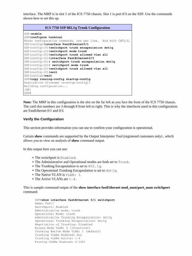
interface. The MRP is in slot 1 of the ICS 7750 chassis. Slot 1 is port 0/3 on the SSP. Use the commandsshown here to set this up.
ICS 7750 SSP 802.1q Trunk Configuration
SSP>enableSSP#configure terminalEnter configuration commands, one per line. End with CNTL/Z.SSP(config)#interface FastEthernet0/1SSP(config−if)#switchport trunk encapsulation dot1qSSP(config−if)#switchport mode trunkSSP(config−if)#switchport trunk allowed vlan allSSP(config−if)#interface FastEthernet0/3SSP(config−if)# switchport trunk encapsulation dot1qSSP(config−if)# switchport mode trunkSSP(config−if)#switchport trunk allowed vlan allSSP(config−if)#exitSSP(config)#exitSSP#copy running−config startup−configDestination filename [startup−config]?Building configuration...[OK]SSP#
Note: The MRP in this configuration is the slot on the far left as you face the front of the ICS 7750 chassis.The card slot numbers are 3 through 8 from left to right. This is why the interfaces used in this configurationare FastEthernet 0/1 and 0/3.
Verify the Configuration
This section provides information you can use to confirm your configuration is operational.
Certain show commands are supported by the Output Interpreter Tool (registered customers only) , whichallows you to view an analysis of show command output.
In this output here you can see:
The switchport is Enabled.• The Administrative and Operational modes are both set to Trunk.• The Trunking Encapsulation is set to 802.1q.• The Operational Trunking Encapsulation is set to dot1q.• The Native VLAN is VLAN: 1.• The Active VLANs are 1−4.•
This is sample command output of the show interface fastEthernet mod_num/port_num switchportcommand.
SSP#show interface fastEthernet 0/1 switchportName: Fa0/1Switchport: EnabledAdministrative mode: trunkOperational Mode: trunkAdministrative Trunking Encapsulation: dot1qOperational Trunking Encapsulation: dot1qNegotiation of Trunking: DisabledAccess Mode VLAN: 0 ((Inactive))Trunking Native Mode VLAN: 1 (default)Trunking VLANs Enabled: ALLTrunking VLANs Active: 1−4Pruning VLANs Enabled: 2−1001

SSP#
Priority for untagged frames: 0Override vlan tag priority: FALSEVoice VLAN: noneAppliance trust: noneSSP#
This is another example of the show interface fastEthernet mod_num/port_num switchport command.
SSP#show interface fastEthernet 0/3 switchportName: Fa0/3Switchport: EnabledAdministrative mode: trunkOperational Mode: trunkAdministrative Trunking Encapsulation: dot1qOperational Trunking Encapsulation: dot1qNegotiation of Trunking: DisabledAccess Mode VLAN: 0 ((Inactive))Trunking Native Mode VLAN: 1 (default)Trunking VLANs Enabled: ALLTrunking VLANs Active: 1−4Pruning VLANs Enabled: 2−1001
Priority for untagged frames: 0Override vlan tag priority: FALSEVoice VLAN: noneAppliance trust: noneSSP#
Troubleshoot the Configuration
There are no steps provided to troubleshootthis part of the configuration.
Configure the VTP Settings on the ICS 7750 SSP
The SSP is a VTP client in this network. Use the commands shown here to set this up.
Caution: The SSP can only support 256 VLANs. If your network has more than 256 VLANs you need
to enable VLAN Pruning to reduce the number of VLANs the SSP sees in VTP advertisements. For furtherinformation, refer to Understanding and Configuring VLAN Trunk Protocol (VTP).
ICS 7750 SSP VTP
SSP>enableSSP#vlan databaseSSP(vlan)#vtp clientSetting device to VTP CLIENT mode.SSP(vlan)#vtp domain tacwebChanging VTP domain name from hhgttg to tacwebSSP(vlan)#vtp password 1P6c3J9zSetting device VLAN database password to 1P6c3J9zSSP(vlan)#exit
!−−− This message appears. Although the message is normal, it is not !−−− completely accurate. It is possible to change some VTP parameters on a VTP Client.!−−− In this case the VTP domain name and password were changed. If this switch !−−− never had a domain name configured, it would have learned it from its upstream VTP!−−− partner. There is no harm in entering the domain name manually.

In CLIENT state, no apply attempted.Exiting....SSP#
Verify the Configuration
This section provides information you can use to confirm your configuration is operational.
Certainshow commands are supported by the Output Interpreter Tool (registered customers only) , whichallows you to view an analysis of show command output.
In the output here you can see:
There are eight known VLANs.• The VTP mode is Client.• The VTP domain is tacweb.•
This is a sample command output of the show vtp status command.
SSP#show vtp statusVTP Version : 2Configuration Revision : 2Maximum VLANs supported locally : 254Number of existing VLANs : 8VTP Operating Mode : ClientVTP Domain Name : tacwebVTP Pruning Mode : DisabledVTP V2 Mode : DisabledVTP Traps Generation : EnabledMD5 digest : 0x25 0x8F 0xFF 0x30 0xEF 0xB1 0xA2 0x57Configuration last modified by 10.21.9.1 at 4−9−93 18:53:07SSP#
In the output here you can see:
Ports 2, 4, 5, 6, 7, and 8 are in VLAN 1 (ports 1 and 3 are trunk ports).• All the VLANs are active.•
Note: VLANs 1002, 1003, 1004, and 1005 are default VLANs. This is why the show vtp status commandsshows eight VLANs: VLAN 1 (default);. VLANs 2−4 that you added and the four remains asdefault VLANs.
This is sample command output of the show vlan brief command.
SSP#show vlan briefVLAN Name Status Ports−−−− −−−−−−−−−−−−−−−−−−−−−−−−−−−−−−−− −−−−−−−−− −−−−−−−−−−−−−−−−−−−−−−−−−−−−−−−1 default active Fa0/2, Fa0/4, Fa0/5, Fa0/6, Fa0/7, Fa0/82 vlan2 active3 vlan3 active4 vlan4 active1002 fddi−default active1003 token−ring−default active1004 fddinet−default active1005 trnet−default activeSSP#
In this output, you can see that the SSP knows about VLANs 2 through 4.

There are additional methods to verify that VTP is operational.. One method is to change the name of aVLAN on the VTP server and verify that the VLAN name change is propagated to the VTP clients. The VTPConfiguration Revision Number should also increase by one.
Troubleshoot the Configuration
There are no steps provided to troubleshoot this part of the configuration.
Configure 802.1q VLANs on the ICS 7750 MRP
The MRP is the inter−VLAN router for this network. Use the commands shown here to set this up.
ICS 7750 MRP 802.1q
MRP>enablePassword:MRP#configure terminalEnter configuration commands, one per line. End with CNTL/Z.MRP(config)#interface FastEthernet0/0MRP(config−if)#ip address 10.21.9.61 255.255.255.0
!−−− Interface 0/0 is the Native VLAN interface that uses untagged frames.!−−− Do not configure 802.1q encapsulation on it.
MRP(config−if)#interface FastEthernet0/0.1MRP(config−if)#encapsulation dot1Q 2MRP(config−if)#ip address 10.21.8.61 255.255.255.0MRP(config−if)#no cdp enableMRP(config−if)#interface FastEthernet0/0.2MRP(config−if)#encapsulation dot1Q 3MRP(config−if)#ip address 10.21.7.61 255.255.255.0MRP(config−if)#no cdp enableMRP(config−if)#interface FastEthernet0/0.3MRP(config−if)#encapsulation dot1Q 4MRP(config−if)#ip address 10.25.14.196 255.255.255.248MRP(config−if)#no cdp enableMRP(config−if)#exitMRP(config)#exitMRP#
Verify the Configuration
This section provides information you can use to confirm your configuration is operational.
Certain show commands are supported by the Output Interpreter Tool (registered customers only) , whichallows you to view an analysis of show command output.
This is a sample command output of the show vlans command.
MRP#show vlans
Virtual LAN ID: 1 (IEEE 802.1Q Encapsulation)
vLAN Trunk Interface: FastEthernet0/0
This is configured as Native VLAN for the following interface(s) :
FastEthernet0/0
Protocols Configured: Address: Received: Transmitted:

IP 10.21.9.61 3664824 3660021
Virtual LAN ID: 2 (IEEE 802.1Q Encapsulation)
vLAN Trunk Interface: FastEthernet0/0.1
Protocols Configured: Address: Received: Transmitted: IP 10.21.8.61 3020581 3116540
Virtual LAN ID: 3 (IEEE 802.1Q Encapsulation)
vLAN Trunk Interface: FastEthernet0/0.2
Protocols Configured: Address: Received: Transmitted: IP 10.21.7.61 100073 82743
Virtual LAN ID: 4 (IEEE 802.1Q Encapsulation)
vLAN Trunk Interface: FastEthernet0/0.3
Protocols Configured: Address: Received: Transmitted: IP 10.25.14.196 157686 34398MRP#
Troubleshoot the Configuration
There are no steps provided to troubleshoot this part of the configuration.
Configure Default IP Routing on the ICS 7750 MRP
Configure the IP routing parameters to set up the MRP as a viable default gateway for remote IP networks thatend−systems on the local network can use.
A thorough explanation of IP routing, default gateways, and gateways of last resort is beyond the scope of thisdocument. The option presented in this document is only one of the possible solutions to ensure adequate IProuting connectivity. For more information on this subject, refer to Configuring a Gateway of Last ResortUsing IP Commands.
In this network design, end−systems on the local network use the IP address of the MRP for the VLAN thatthey are connected to as their default gateway. For instance, a device on VLAN 3 will have 10.21.7.61configured as its default gateway. If the IP traffic is destined for remote IP networks, the MRP forwards thetraffic to the other router in the network diagram over VLAN 4.
Use the commands shown here to set this up.
ICS 7750 MRP Default Network; Gateway of Last Resort
MRP>enablePassword:MRP#configure terminalEnter configuration commands, one per line. End with CNTL/Z.MRP(config)#MRP(config)#ip classlessMRP(config)#ip default−network 0.0.0.0MRP(config)#ip route 0.0.0.0 0.0.0.0 10.25.14.193MRP(config−if)#exitMRP(config)#exitMRP#
Verify the Configuration
This section provides information you can use to confirm your configuration is operational.
Certain show commands are supported by the Output Interpreter Tool (registered customers only) , whichallows you to view an analysis of show command output.
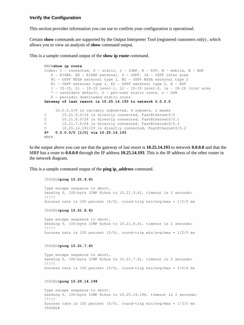
This is a sample command output of the show ip route command.
MRP#show ip routeCodes: C − connected, S − static, I − IGRP, R − RIP, M − mobile, B − BGP D − EIGRP, EX − EIGRP external, O − OSPF, IA − OSPF inter area N1 − OSPF NSSA external type 1, N2 − OSPF NSSA external type 2 E1 − OSPF external type 1, E2 − OSPF external type 2, E − EGP i − IS−IS, L1 − IS−IS level−1, L2 − IS−IS level−2, ia − IS−IS inter area * − candidate default, U − per−user static route, o − ODR P − periodic downloaded static routeGateway of last resort is 10.25.14.193 to network 0.0.0.0
10.0.0.0/8 is variably subnetted, 4 subnets, 2 masksC 10.21.9.0/24 is directly connected, FastEthernet0/0C 10.21.8.0/24 is directly connected, FastEthernet0/0.1C 10.21.7.0/24 is directly connected, FastEthernet0/0.3C 10.25.14.192/29 is directly connected, FastEthernet0/0.2S* 0.0.0.0/0 [1/0] via 10.25.14.193MRP#
In the output above you can see that the gateway of last resort is 10.25.14.193 to network 0.0.0.0 and that theMRP has a route to 0.0.0.0 through the IP address 10.25.14.193. This is the IP address of the other router inthe network diagram.
This is a sample command output of the ping ip_address command.
3500XL#ping 10.21.9.61
Type escape sequence to abort.Sending 5, 100−byte ICMP Echos to 10.21.9.61, timeout is 2 seconds:!!!!!Success rate is 100 percent (5/5), round−trip min/avg/max = 1/2/5 ms
3500XL#ping 10.21.8.61
Type escape sequence to abort.Sending 5, 100−byte ICMP Echos to 10.21.8.61, timeout is 2 seconds:!!!!!Success rate is 100 percent (5/5), round−trip min/avg/max = 1/2/5 ms
3500XL#ping 10.21.7.61
Type escape sequence to abort.Sending 5, 100−byte ICMP Echos to 10.21.7.61, timeout is 2 seconds:!!!!!Success rate is 100 percent (5/5), round−trip min/avg/max = 5/5/6 ms
3500XL#ping 10.25.14.196
Type escape sequence to abort.Sending 5, 100−byte ICMP Echos to 10.25.14.196, timeout is 2 seconds:!!!!!Success rate is 100 percent (5/5), round−trip min/avg/max = 1/3/5 ms3500XL#

3500XL#ping 10.25.14.193
Type escape sequence to abort.Sending 5, 100−byte ICMP Echos to 10.25.14.196, timeout is 2 seconds:!!!!!Success rate is 100 percent (5/5), round−trip min/avg/max = 1/3/5 ms3500XL#
In the output above you can see that the 3500 switch is able to ping each of the subnet addresses assigned tothe VLANs on the MRP. 10.21.9.61 is the Native VLAN (VLAN 1) that uses untagged frames.
Troubleshoot the Configuration
There are no steps provided to troubleshoot this part of the configuration.
Using ICSConfig on the SM SPE to Configure the Default Gateway for theCards in the Chassis
In this task you must verify, and if required, change the default gateway for the cards in the chassis.
Access Internet Explorer on the SM SPE or another device that has connectivity to the SM SPE.1. Start ICSConfig and enter the url http://ip_address/icsconfig.
The CheckDiscovery process begins.
2.

When the CheckDiscovery process finishes, you are prompted to click Continue with ICSConfig.3.

When the ICS 7700 System Configuration Menu appears, click ICS 7700 System Setup.4.

The Summary screen appears and shows the current settings. Scroll down to the section namedNetwork Configuration−DNS and Gateway.
In this case, the default gateway is already setup correctly. The remainder of this task shows you howto change this setting if you need to.
If your system is already setup properly, you do not need to complete this task. Click Cancel andclose all of the open windows.
If you need to change this setting continue with this task. Click the Network Configuration−DNSand Gateway link.
5.

When the menu to change the default gateway appears, enter the correct IP address and clickContinue.
6.
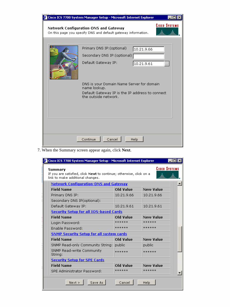
When the Summary screen appear again, click Next.7.

When the Ready to Submit screen appears, click Submit.8.
Wait until the Setup In Progress screen completes.9.

When prompted, click Close Window.10.

Verify the Configuration
There are no specific verification steps for this task. Proceed to the Verify section below.
Troubleshoot the Configuration
There are no specific to troubleshoot steps for this task. Proceed to the Verify section below.
Verify
This section provides information you can use to confirm your configuration is working properly.
Certain show commands are supported by the Output Interpreter Tool (registered customers only) , whichallows you to view an analysis of show command output.
You can verify that the SPE cards can access end systems on VLANs 2 through 4 with the help of the pingcommand from a DOS prompt to ping the IP addresses on the MRP for the other VLANs.
Select Start > Run > cmd [Enter] on the console of any of the SPEs.1. Ping the IP addresses on the MRP.
Note: Because the SPEs are on VLAN 1 (subnet 10.21.9.0) you do not need to ping the MRP'sinterface for this VLAN. This step is included below to show that the SPE can access all of thesubnets in this configuration.
C:\>ping 10.21.9.61
Pinging 10.21.9.61 with 32 bytes of data:
Reply from 10.21.9.61: bytes=32 time<10ms TTL=255Reply from 10.21.9.61: bytes=32 time=10ms TTL=255Reply from 10.21.9.61: bytes=32 time=10ms TTL=255Reply from 10.21.9.61: bytes=32 time=10ms TTL=255
Ping statistics for 10.21.9.61:Packets: Sent = 4, Received = 4, Lost = 0 (0% loss),Approximate round trip times in milli−seconds:Minimum = 0ms, Maximum = 10ms, Average = 7ms
C:\>ping 10.21.8.61
Pinging 10.21.8.61 with 32 bytes of data:
Reply from 10.21.8.61: bytes=32 time<10ms TTL=255Reply from 10.21.8.61: bytes=32 time<10ms TTL=255Reply from 10.21.8.61: bytes=32 time<10ms TTL=255Reply from 10.21.8.61: bytes=32 time<10ms TTL=255
Ping statistics for 10.21.8.61:Packets: Sent = 4, Received = 4, Lost = 0 (0% loss),Approximate round trip times in milli−seconds:Minimum = 0ms, Maximum = 0ms, Average = 0ms
C:\>ping 10.21.7.61
Pinging 10.21.7.61 with 32 bytes of data:
Reply from 10.21.7.61: bytes=32 time<10ms TTL=255Reply from 10.21.7.61: bytes=32 time<10ms TTL=255Reply from 10.21.7.61: bytes=32 time<10ms TTL=255
2.

Reply from 10.21.7.61: bytes=32 time<10ms TTL=255
Ping statistics for 10.21.7.61:Packets: Sent = 4, Received = 4, Lost = 0 (0% loss),Approximate round trip times in milli−seconds:Minimum = 0ms, Maximum = 0ms, Average = 0ms
C:\>ping 10.25.14.196
Pinging 10.25.14.196 with 32 bytes of data:
Reply from 10.25.14.196: bytes=32 time=10ms TTL=255Reply from 10.25.14.196: bytes=32 time=10ms TTL=255Reply from 10.25.14.196: bytes=32 time=10ms TTL=255Reply from 10.25.14.196: bytes=32 time=10ms TTL=255
Ping statistics for 10.25.14.196:Packets: Sent = 4, Received = 4, Lost = 0 (0% loss),Approximate round trip times in milli−seconds:Minimum = 10ms, Maximum = 10ms, Average = 10ms
C:\>ping 10.25.14.193
Pinging 10.25.14.193 with 32 bytes of data:
Reply from 10.25.14.193: bytes=32 time<10ms TTL=128Reply from 10.25.14.193: bytes=32 time<10ms TTL=128Reply from 10.25.14.193: bytes=32 time<10ms TTL=128Reply from 10.25.14.193: bytes=32 time<10ms TTL=128
Ping statistics for 10.25.14.193:Packets: Sent = 4, Received = 4, Lost = 0 (0% loss),Approximate round trip times in milli−seconds:Minimum = 0ms, Maximum = 0ms, Average = 0ms
C:\>
Troubleshoot
The most common cause of inter−VLAN routing problems are configuration errors.
It is also possible that there are static IP routes on the SPEs that are overriding the default gateway setting.Use the c:\> netstat −rn command in a DOS prompt on the SPEs to verify the current routing table. Deleteany conflict routes and try the test again. If the routes come into conflict then you must determine how theywere created and prevent them from its occurs again..
Related Information
Release Notes for System Software Release 2.5.0 on the Cisco ICS 7750• Release Notes for System Software Release 2.6.0 on the Cisco ICS 7750• Virtual LANs/VLAN Trunking Protocol (VLANs/VTP) Support Page• Voice Technology Support• Voice and Unified Communications Product Support• Troubleshooting Cisco IP Telephony • Technical Support & Documentation − Cisco Systems•
Contacts & Feedback | Help | Site Map© 2013 − 2014 Cisco Systems, Inc. All rights reserved. Terms & Conditions | Privacy Statement | Cookie Policy | Trademarks ofCisco Systems, Inc.

Updated: Dec 13, 2005 Document ID: 41662