implementation of recursive least square method in …€¦ · · 2017-10-01abstract— this...
TRANSCRIPT
Abstract— This paper proposes implementation of Recursive
Least Square (RLS) method in a self-adaptive technique for
Active Power Filter (APF) control. APF are used to reduce the
Total Harmonic Distortion (THD) in power system. Namely,
APF compensate higher harmonics present in the power grid. In
order to compensate, the higher harmonics should be identified,
at first. The real truth is that nonlinear loads mainly distort the
current. Therefore the distortion current is to be measured and
all harmonic components identified. RLS method uses values of
the sampled current to calculate the needed compensation for
APF. Then APF (in shunt configuration) add to the grid the
required higher harmonic components of current diminishing
distortion on the grid. Simulations by SystemC verify the
effectiveness of the method.
Index Terms—Active power filters; Power grid; Power
harmonics; Recursive Least Squares algorithm.
I. INTRODUCTION
All loads connected to a power grid can be categorized as
linear and non-linear loads. The linear load causes the current
drawn from the power grid to be proportional to the applied
voltage. If the load impedance changes with the applied
voltage, the load is defined as non-linear. In this case, the
current drawn from the grid does not follow the voltage
linearly and it is not sinusoidal. It contains higher harmonics.
Consequently, the distributed power, apart from active and
reactive, receives another component, known as distortion
power. This power is mainly nonvisible to the utility and is
manifested as losses on the grid [1].
The number of nonlinear loads has been increased
enormously in last few decades. Nonlinearity is typical for
AC-DC converters, variable frequency drives, discharge
lighting, etc. The problem has augmented with the effort to
make much effective converters where active devices operate
in switching mode. The good news is that contemporary
electronics requires much less power per an appliance.
However the bad news is that the number of electronic
gadgets is huge. In total, the distortion part of the consumed
power has become significant and reaches the same order of
magnitude as active power [2]. Therefore it should be
diminished. The main strategy in dealing with this problem is
to strike at the point at which it is generated. The nonlinear
loads introduce harmonics into the grid and they are sources
Borisav Jovanović, Predrag Petković and Srđan Milenković are with The
Faculty of Electronic Engineering, University of Niš, Aleksandra Medvedeva
street, 18000 Niš, Serbia (e-mail: {borisav.jovanovic, predrag.petkovic}
@elfak.ni.ac.rs, [email protected]).
of harmonics. Therefore it is natural to provide some kind of
drain for harmonics, trying to compensate them.
The real answer to this challenge has come from using
Active Power Filters (APF) [3]. Their role is to introduce new
harmonics to the grid. In order to compensate existing
harmonics, the new should have the same magnitude but the
opposite phase. This can be done only if
1. magnitude and phase values of the presented harmonics
are known,
2. there is possibility to add to the grid required harmonics.
Consequently, the system that compensate harmonics has to
consist of a measuring module, some computing engine that
calculate harmonics, control module that drives actuators
capable to provide required harmonics to the grid.
Practically it means that one need to have a reservoir from
which the loss that appears as the distortion power would be
supplemented. The contemporary grid systems are enriched
with such reservoirs. Basically, all alternative power sources
like photovoltaic (PV) panels, wind farms, even any other DC
supply are to be connected to the grid using DC/AC
converters. The tricky part is how to control the converter in
order to produce signal with required harmonics pattern.
This paper suggests implementation of Recursive Least
Square (RLS) method in a self-adaptive technique for Active
Power Filter (APF) control.
The following section describes principles of APF. The
third section explains the use of RLS method for APF control.
The idea is verifies by SystemC simulation. The obtained
results are presented the fourth section that precedes to the
concluding section.
II. ACTIVE POWER FILTERS
Active power filters (APF) are now relatively common in
industrial applications for both harmonic mitigation and
reactive power compensation [4]. The APF ensures the power
grid current to be almost sinusoidal and in-phase with the
source voltage signal [5]. Besides, the APF improves the
power quality in order to impose a unity power factor. Shunt-
connected APF, positioned in parallel with the nonlinear load,
is the common configuration of the APF [6].
The APF is comprised of the IGBT bridge and DC bus
architecture similar to that seen in alternating current pulse-
width modulation drives. The direct current bus is used as an
energy storage unit [6].
Implementation of Recursive Least Square
Method in Active Power Filters Control
Borisav Jovanović, Predrag Petković, Srđan Milenković
Proceedings of 4th International Conference on Electrical, Electronics and Computing Engineering, IcETRAN 2017, Kladovo, Serbia, June 05-08, ISBN 978-86-7466-692-0
pp. ELI2.5.1-4
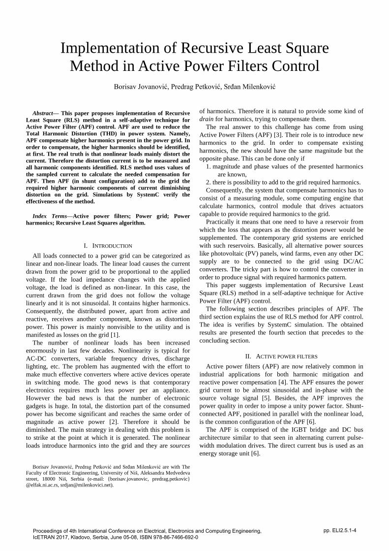
Fig. 1. Typical connections of Active power filter.
The APF operation is based on measured data of the
distorted current drown from the nonlinear load. It is depicted
in Fig. 1 as iL. The measured results are fed to the embedded
microprocessor to calculate harmonics and to generate the
corresponding IGBT firing patterns that will provide the
compensation current capable to cancel harmonics. This
current is denoted as iC in Fig. 1. As result, the total grid
current (iG in Fig. 1) is the difference of the distortion current
and the compensation current. In order to make iG cleared of
harmonics, APF should add to the grid current that has the
same amount of higher harmonics but with opposite phase of
the distortion current [4].
The proposed method is focused on improving the quality
of the power system. The method can be divided into two
parts. In the first part, the distortion current is measured and
processed. The outcomes are the amplitudes and phases of all
harmonic components. In the second part, the compensation
current signal is generated which is then subtracted from the
distortion current to form harmonic-free grid current.
The aim of this paper is not to consider DC to AC converter
and its driver that produces the compensation current. Instead,
we want to prove a new concept of APF control based on RLS
algorithm for harmonic detection and adaptive active filtering
[5].
III. THE UTILIZATION OF THE RECURSIVE LEAST SQUARES
METHOD IN IMPLEMENTATION OF APF
When nonlinear loads are present in a power system, the
load current waveforms are periodic but non-sinusoidal.
According to Fourier series theory any periodic waveform can
be represented as a sum of its harmonic components.
Implemented in discrete domain when sampled with fs, the n-
th sample of the load current signal iL(n), can be expressed as
follows:
K
i
iiL fniAni1
)2sin()( , (1)
where f=50/fs is the fundamental frequency of 50Hz, which is
normalized to sampling frequency value fs. The Ai and φi
represent the amplitude and the phase of the i-th harmonic of
the load current signal. K is the order of the highest harmonic.
Equation (1) can be transformed into the following equation:
K
i
iiiiL fniAfniAni1
2cossin2sincos)( (2)
It is practical to store components of expression (2) in form
of two vectors sized as 2×K. One of them, denoted x(n), stores
sin(2πfni) and cos(2πfni) pairs for each i=1,...,K:
Kii
Kii
Tj
fninx
fninx
nxnKj
,...,12
,...,112
)2cos()(
)2sin()(
)()(2,...,1
x
. (3)
Another, denoted w(n), stores pairs of amplitudes related to
cosine (Ai cos φi) and sine (Ai sin φi) components of harmonics
for each i=1,...,K:
Kiiii
Kiiii
Tj
nAnw
nAnw
wnKj
,...,12
,...,112
sin)()(
cos)()(
)(2,...,1
w
. (4)
The scalar value iL(n) can be expressed as a product of the
two vectors:
)()()( nnni TL wx . (5)
In order to obtain all harmonic components of the load
current one needs to know w(n). The amplitudes and phases
of the i-th harmonic components are:
222
22
12 )sin()cos( iiiiiii AAwwA (6)
12
2arctan
i
ii
w
w (7)
If w(n) is known, any harmonic waveform can be easily
reconstructed. For example, component of iLi(n) with
frequency f, can be expressed as:
fniAfniAni iiiiLi 2cossin2sincos)( (8)
)()()( 221212 nxwnxwni iiiiLi (9)
The elements of vector x(n) are considered as known
because fundamental frequency, and frequency of all required
harmonics, are known so that cosine and sine values for all
harmonic components can be easily calculated. The elements
of vector w(n), which contain information about amplitudes
and phases of harmonic components, are unknown and have
to be determined. For this purpose we suggest using adaptive
filtering based on the iterative RLS method [7].
Let the iL(n) denote the referent input signal (the distortion
current signal). In each iteration, for every new input sample
iL(n), new elements of the vector w(n) should be calculated.
Formally, when w(n) is substituted in (5) the obtained iL’(n)

will differ from the referent value iL(n). The discrepancy
indicates the calculation error ε(n) expressed with:
)()()()(')( )( nnnininin TLLL wx (10)
The RLS method is implemented as an adaptive filter
which recursively finds the coefficients that minimize a
weighted linear least squares cost function relating to the
input signals. The cost function E(n), used for RLS
minimization of error function ε(n) is:
n
m
mn mnE0
2)(2
1)( (11)
where λ is the "forgetting factor" giving exponentially less
weight to older error samples. The smaller λ is, the smaller
contribution of previous samples. In practice, λ is usually
chosen between 0.98 and 1 [7].
The cost function E(n) given in (11) is in contrast to other
algorithms such as the least mean squares (LMS) that aim to
reduce the mean square error. Compared to the other recursive
algorithms, the RLS manifests fast convergence. This benefit
comes at the cost of high computational complexity [7].
Fortunately, today even complicated mathematics is easily
handled at low-cost contemporary hardware.
The RLS iterative algorithm is derived by minimization of
cost function E(n) which is achieved by taking the partial
derivatives for all parameters wi and setting the results to zero:
0)(
iw
nE (12)
When RLS algorithm converge, the error function ε(n) is
zero and the signals iL(n) and iL’(n) become equal.
IV. THE IMPLEMENTATION OF APF IN SYSTEMC
The model of Harmonic Distortion Corrector, which is
based on utilization of Recursive Least Squares algorithm, has
been implemented in SystemC. The SystemC is a set of C++
classes which provide an event-driven simulation interface
and can be applied to system-level modeling, functional
verification and high-level synthesis [8]. SystemC can
simulate real-time environments, using signals of all the
datatypes offered by standard C++, additional ones offered by
the SystemC library, as well as user defined libraries [8]. In
certain respects SystemC has semantic similarities to
hardware description languages such as VHDL and Verilog,
but is more oriented to system-level modeling. The source
code is compiled to an executable file.
Fig. 2. The Active power filter simulation test-bench
The simulation test-bench is given in Fig.2. It consists of
concurrent processes which are described using plain C++
syntax. The test-bench contains following instances:
RLS based Active power filter,
delay circuit having the same delay as APF,
measured in number of clock cycles,
subtraction circuit, producing grid current iG[n],
current signal probes, storing these results into the
binary log file.
The APF system takes at input the distortion current
samples iL[n], sampled at frequency of 20 kHz. The distortion
current is generated within the test-bench using data from
Table 1. Beside, one of inputs of APF is harmonic selection
bus, which is used for selection of those harmonic
components which should be eliminated from the grid current
iG[n]. Therefore, we have an option to choose the harmonic
content of the grid current. The width of this bus is K, where
K is the harmonic order. In simulations, we have chosen
K=10, meaning that the fundamental frequency and following
nine higher harmonics are only identified. Besides, only the
fundamental frequency of iG[n] is enabled and all higher
harmonics are eliminated. The forgetting factor λ of RLS
method is chosen to be equal to 0.98. The signal samples are
defined with double C data type.
TABLE I
HARMONIC CONTENT FOR DIFFERENT SIMULATED NON-LINEAR LOADS
Harmonic
order
Philips
CFL lamp
Computer
power
supply
Power converter
for variable
speed motors
1 100/32° 100/-12° 100/0°
3 86/-107° 81/135° 9/60°
5 60/124° 61/-70° 70/70°
7 34/7° 37/83° 60/-150°
9 21.7/-82° 16/-115° 6/30°
Three different non-linear loads were simulated:
the Philips CFL lamp
for 6-pulse computer power supply
pulse PWM controlled power converter for variable
speed motors [9]

Fig. 3. The demonstration of harmonic compensation for Philips CFL lamp: top panel presents the non-linear load current iL[n], middle - compensation
current iC[n] and bottom panel displays the grid current iG[n]
Fig. 4. The demonstration of harmonics compensation for 6-pulse computer
power supply, top panel presents the non-linear load current iL[n], middle - compensation current iC[n] and bottom panel is the power grid current iG[n]
Fig. 5. The demonstration of harmonics compensation for 6- pulse PWM controlled power converter for variable speed motors, top panel presents the
non-linear load current iL[n], middle - compensation current iC[n] and bottom
panel is the grid current iG[n]
The harmonic amplitudes and phases of input stimuli which
are taken from [1], are defined in Table 1 and the results are
presented in Figures 3 to 5. The top panel presents original
distortion current waveform, the middle presents the
compensation current and the bottom panel displays the
resulting grid current. As it can be seen in figures, during the
RLS training period, lasting 1000 data samples, the elements
of vector w[n] are calculated. After the training period is
finished, the compensation current is calculated and applied to
distortion current. Then, the resulting grid current becomes
sinusoidal.
The proposed method manifests adaptive behavior; the
system is able to continuously track changes of distortion
current and automatically update the coefficients of vector
w[n].
V. CONCLUSION
The Active power filter (APF) is used for harmonics
mitigation. This paper suggests using the iterative Recursive
Least Square method for APF implementation. First, the
harmonic components of distortion current signal are
determined. After that, the higher harmonics are reconstructed
and subtracted from distortion current. The resulting grid
current becomes pure sinusoidal. We have built the SystemC
simulation model of the APF system. Simulation results show
that the method is feasible and works in real-time. The
superior performance and the good dynamic response have
been assured by simulation results, but there is still a lot of
experimental research to do in the future.
ACKNOWLEDGMENT
Results described in this paper are obtained within the project
TR32004 founded by Serbian Ministry of Education, Science
and Technological Development.
REFERENCES
[1] Stevanović D., Petković, P., "A Single-Point Method for Identification
Sources of Harmonic Pollution Applicable to Standard Power Meters",
Electrical Engineering, Volume 97, Issue 2, ISSN 0948-7921(prn), ISSN 1432-0487(online), doi:10.1007/s00202-014-0324-z, June 2015,
pp 165-174.
[2] Petković, P., Stevanović, D., "Detection of power grid harmonic pollution sources based on upgraded power meters", Journal of
Electrical Engineering, vol. 65, No. 3, 2014, pp. 163-168.
[3] H. Akagi, “New Trends in Active Filters for Power Conditioning,” IEEE Transactions on Industry Applications, Vol. 32, No. 6, 1996, pp.
1312-1322, also in Proceedings of International Conference on Power
Electronics, Drives and Energy Systems for Industrial Growth, 8-11 Jan. 1996, New Delhi, India, DOI: 10.1109/PEDES.1996.539652.
[4] S Rani, C. S. Rao, M. V. Kumar, “Analysis of active power filter for
harmonic mitigation in distribution system“, Int. Conf. on Electrical, Electronics and Optimization Techniques (ICEEOT), 3-5 3. 2016, India.
[5] L. Asiminoaei, F. Blaabjerg, and S. Hansen, “Detection is key —
harmonic detection methods for active power filter applications”, IEEE Industry Applications Magazine, Vol. 13, No. 4, pp. 22–33, 2007.
[6] J B. Singh, J. Solanki, “An implementation of an adaptive control algorithm for a three-phase shunt active filter”, IEEE Transactions on
Industrial Electronics, Vol. 56, No. 8, pp. 2811-2820, 2009
[7] B. Widrow, J. R. Glover, J. M. McCool, at al., “Adaptive noise cancelling: Principles and Applications“, Proceedings of the IEEE, Vol.
63, No.12, pp. 1692-1716, 1975
[8] SystemC, http://accellera.org/downloads/standards/systemc [9] R. R. Pereira, C. H. Silva, L. E. Silva, G. L. Torres, J. P. Pinto, New
strategy for application of adaptive filters in active power filter, IEEE
Transactions on Industrial Applications, 47 (3) (2011) pp. 1136-1141.