implementation of a virtual autonomous excavator
TRANSCRIPT

Hong-Seok Park Duc-Viet Dang Trung-Thanh Nguyen Ngoc-Tran Le
https://doi.org/10.21278/TOF.41306 ISSN 1333-1124
eISSN 1849-1391
IMPLEMENTATION OF A VIRTUAL AUTONOMOUS EXCAVATOR
Summary
Automation of digging processes is a way to improve building efficiency and prevent workplace accidents. The objective of this study was to develop an intelligent excavator by means of virtual prototyping technology which takes working disturbances into consideration. Firstly, a multi-body simulation model (MBS) was developed to investigate the excavator behaviour and reaction forces with respect to soil characteristics. Subsequently, an adaptive sliding-mode PID controller with a fuzzy compensator (ASMPIDF) was proposed to perform autonomous functions. Finally, a co-simulation of the mechanical model and the virtual controller was conducted to derive adaptive trajectories of the excavator joints. The low simulated values of overshoot, settling time, and steady-state error demonstrate that the proposed approach is feasible and effective in developing intelligent behaviours of the excavator. Therefore, this study is expected to contribute to digging processes to become safer and more efficient.
Key words: autonomous excavator, digging process, virtual prototyping, multi-body simulation
1. Introduction
The construction industry accounts for approximately 7-12% of the total Gross Domestic Product, in which building processes dominate [1]. Digging processes are widely used in a variety of building preparations to remove material from solid surfaces. Because excavation is a common construction process, improvements to excavator machinery are considered to be promising as a way to improve digging productivity. Digging efficiency has historically been poor due to difficult building conditions and lack of process automation. Furthermore, excavator operators can lose concentration due to noisy and hazardous environments, which can lead to workplace accidents. Consequently, it is urgently necessary to develop intelligent behaviours of excavators to automate building operations and improve digging efficiency.
Modelling of digging processes and the realization of excavator automation have attracted the attention of many researchers. Efforts aimed at modelling the digging process have included calculation methods to estimate the reaction force based on the principle of the
TRANSACTIONS OF FAMENA XLI-3 (2017) 65
H.S. Park, D.V. Dang, Implementation of a Virtual Autonomous Excavator T.T. Nguyen, N.T. Le
fundamental equality of earth moving mechanics [2,3]. Moreover, mathematical models have been developed to predict interactive forces between the blade and the soil [4,5]. Excavators equipped with perception systems have been described that recognize the digging environment and generate possible dig paths [6,7]. In addition, fuzzy logic using human heuristics and expert knowledge has been applied to control digging operations [8,9]. However, the aforementioned efforts have not included thorough considerations of the complex interactions between the excavator and the soil. Development of intelligent behaviours and optimizations of bucket paths based on such considerations could improve digging efficiency.
Physical experiments to study the digging process can be both time-consuming and expensive. Fortunately, literature reviews have revealed that approaches based upon virtual prototyping, using well-defined material properties, numerical models, and controllers can be considered as an intelligent solution that yield reliable results. Virtual prototypes of industrial equipment have been proposed to investigate dynamic behaviour in the initial stage [10,11,12,13]. Significant savings in time and cost can be realized during the design phase by iterating such models until the virtual performance meets the requirements. The results of the aforementioned efforts indicated that virtual prototyping techniques could be considered as a powerful approach to generate intelligent excavator behaviour and to predict the digging performance.
To improve the digging efficiency and avoid accidents, an autonomous function of an excavator using a multi body simulation (MBS) model and an intelligent control system is considered in this paper. This construction equipment was chosen for the study due to its wide application in building operations. Therefore, it is essential to have a reliable numerical model to conduct parametric studies and optimize controlling parameters in terms of the digging operations. Moreover, we found that varying the soil hardness and the presence or location of unidentified obstacles contributed to variations in the measured reaction forces and the digging efficiency. Therefore, an effective approach that describes the digging process behaviour and optimizes the controlling parameters of a smart excavator is an important area of research. The scientific methodology used to tackle these issues is introduced in the next section.
2. Research methodology
To our best knowledge, there is no commercial simulation tool that directly develops autonomous behaviours of an excavator. Moreover, predicting the reaction forces during digging processes by means of analytical methods is ineffective due to variations of soil hardness. For these reasons, a framework is proposed herein to develop an autonomous excavator, based on a multi-body simulation model (MBS), numerical experiments, and an intelligent virtual controller (Fig. 1). Firstly, the digging process was investigated to identify the necessary tasks of the excavator. A synthetic simulation model, including the excavator structure and soil characteristics was then developed to describe a reliable digging process. The body relationships, the degrees of freedom, space motions, joint types, and geometric constraints of the excavator and soil properties were determined in the integrative simulation model. Subsequently, the dynamic simulation was conducted to identify the excavator behaviour and reaction forces with respect to ground environments. Next, an intelligent controller was developed and integrated into the mechanical model to construct a virtual prototyping excavator. Finally, co-simulations were performed to generate adaptive trajectories of the excavator joints during digging processes.
66 TRANSACTIONS OF FAMENA XLI-3 (2017)

Implementation of a Virtual Autonomous Excavator H.S. Park, D.V. Dang, T.T. Nguyen, N.T. Le
Fig. 1 Systematic procedure for developing
autonomous excavator Fig. 2 Sequenced tasks in the digging cycle
3. Multi-body simulation model (MBS) of the excavator
3.1 Digging tasks of the excavator The excavation process is complicated because of the complexity of the machine
structure and the interactions between the bucket and the ground. An excavator digging cycle can be divided into the following steps, as illustrated in Fig. 2:
Step 1: The bucket starts in a position over the trench. Step 2: The boom is moved to make the bucket get into contact with the ground. Step 3: The excavator determines the bucket path and angle based on the terrain profile
data and the reaction force. Step 4: The bucket is operated to move through the ground to collect soil, including
penetration, drag, and curl moves. Step 5: The boom is raised to remove the bucket from the trench, and thus to remove the
soil from the ground. Step 6: The excavator rotates and then dumps soil at the side of the trench. Step 7: The digging process is repeated with the empty bucket. The behaviour of the bucket is considered to be crucial for optimizing the digging
process. Steps 3 and 4 are key operations requiring the identification of the bucket-soil interaction and the generation of adaptive bucket paths. Based on the soil characteristics as well as the conditions of any encounters between the bucket and buried obstacles, the excavator can be operated according to the following digging strategies:
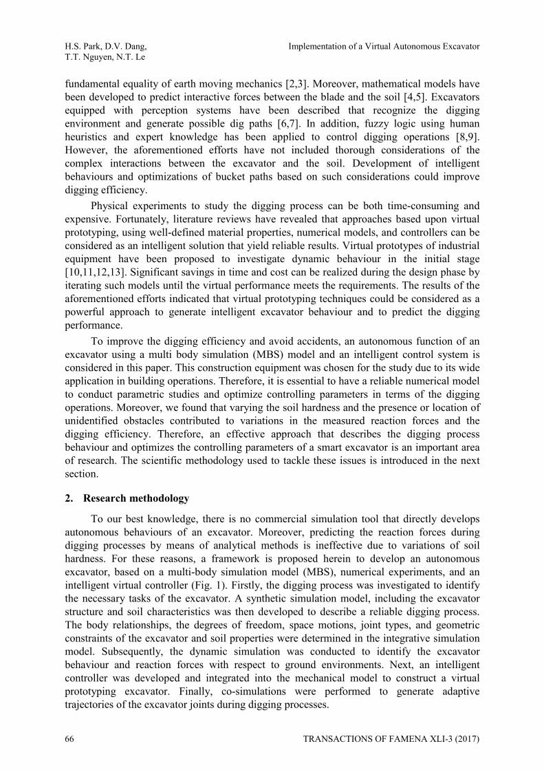
Penetration and curl: This strategy is used to excavate soft soils, which produce low reaction forces. The bucket is moved into the ground vertically. Once the desired penetration depth is reached, the bucket is curled to collect soil (Fig. 3a).
Penetration, drag, and curl: This strategy is used to dig hard soils, which are difficult to penetrate and they produce high reaction forces. Boom joints are used to control the bucket when it penetrates the soil. The bucket tooth is then dragged in a straight line to collect the soil (Fig. 3b).
TRANSACTIONS OF FAMENA XLI-3 (2017) 67
H.S. Park, D.V. Dang, Implementation of a Virtual Autonomous Excavator T.T. Nguyen, N.T. Le
(a) Penetration and rotation (soft soil) (b) Penetration, drag and curl (hard soil) Fig. 3 Basic digging strategies
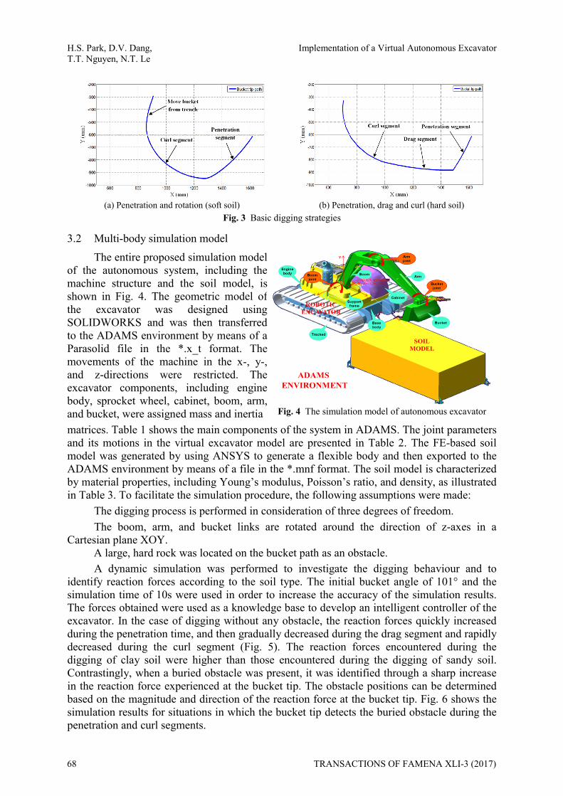
3.2 Multi-body simulation model The entire proposed simulation model
of the autonomous system, including themachine structure and the soil model, isshown in Fig. 4. The geometric model ofthe excavator was designed usingSOLIDWORKS and was then transferredto the ADAMS environment by means of aParasolid file in the *.x_t format. Themovements of the machine in the x-, y-, and z-directions were restricted. Theexcavator components, including enginebody, sprocket wheel, cabinet, boom, arm,and bucket, were assigned mass and inertia Fig. 4 The simulation model of autonomous excavator matrices. Table 1 shows the main components of the system in ADAMS. The joint parameters and its motions in the virtual excavator model are presented in Table 2. The FE-based soil model was generated by using ANSYS to generate a flexible body and then exported to the ADAMS environment by means of a file in the *.mnf format. The soil model is characterized by material properties, including Young’s modulus, Poisson’s ratio, and density, as illustrated in Table 3. To facilitate the simulation procedure, the following assumptions were made:
The digging process is performed in consideration of three degrees of freedom. The boom, arm, and bucket links are rotated around the direction of z-axes in a
Cartesian plane XOY. A large, hard rock was located on the bucket path as an obstacle. A dynamic simulation was performed to investigate the digging behaviour and to
identify reaction forces according to the soil type. The initial bucket angle of 101° and the simulation time of 10s were used in order to increase the accuracy of the simulation results. The forces obtained were used as a knowledge base to develop an intelligent controller of the excavator. In the case of digging without any obstacle, the reaction forces quickly increased during the penetration time, and then gradually decreased during the drag segment and rapidly decreased during the curl segment (Fig. 5). The reaction forces encountered during the digging of clay soil were higher than those encountered during the digging of sandy soil. Contrastingly, when a buried obstacle was present, it was identified through a sharp increase in the reaction force experienced at the bucket tip. The obstacle positions can be determined based on the magnitude and direction of the reaction force at the bucket tip. Fig. 6 shows the simulation results for situations in which the bucket tip detects the buried obstacle during the penetration and curl segments.
68 TRANSACTIONS OF FAMENA XLI-3 (2017)

Implementation of a Virtual Autonomous Excavator H.S. Park, D.V. Dang, T.T. Nguyen, N.T. Le
Table 1 Parameters of the main links of the virtual excavator prototype
Parts Length (m) Mass (kg) Ixx (kg m2) Iyy (kg m2) Izz(kg m2)
Boom 1.05 26.10 3.23x10² 3.05x10² 2.63x10²
Arm 0.84 17.65 1.35x10² 1.30x10² 6.41
Bucket 0.42 9.08 16.8 11.7 11.2
Table 2 Main joints and motions of the autonomous excavator model
Joint Motion Action
Boom SForce (revolute joint) Drive the boom link
Arm SForce (revolute joint) Drive the arm link
Bucket SForce (revolute joint) Drive the bucket
Bucket_ground_contact Reactive force Interaction between bucket & soil
Table 3 Parameter values used to model the soil prototypes
Soil types Young’s modulus (MPa) Poisson’s ratio Density (kg/m3)
Sandy soil 10 0.36 1800
Clay soil 20 0.30 1900
(a) Soft soil (b) Hard soil Fig. 5 Reaction forces in the case when there is no obstacle
(a) Obstacle encountered during penetration (b) Obstacle encountered during curls Fig. 6 Reaction forces in the case when there is some obstacle
4. Development of the virtual controller
The framework of autonomous excavator operation under disturbance conditions is illustrated in Fig. 7. Standard bucket paths are generated considering the reaction forces between the excavator and the soil. These trajectories are then converted to angle values of
TRANSACTIONS OF FAMENA XLI-3 (2017) 69

H.S. Park, D.V. Dang, Implementation of a Virtual Autonomous Excavator T.T. Nguyen, N.T. Le
Fig. 7 Flowchart of autonomous excavator digging operation under disturbance conditions
the boom, the arm, and the bucket by means of kinematic equations. Subsequently, the excavator joints are simultaneously controlled by adaptive controllers for the digging tasks to be conducted during the cycle. If obstacles are encountered, new bucket trajectories are generated to avoid collisions.
4.1 Inverse kinematic equation The inverse kinematic equation is used to determine the joint angles from the given
points of the bucket path. Fig. 8 illustrates the coordinates of the points attached to the joints (O1, O2, O3, and O4). The lengths of the boom, the arm, and the bucket are expressed as a1, a2, and a3, respectively. The position of the joint (xBj, yBj) is determined based on the bucket tip position as follows:
3 cosBj Btx x a (1)
3 sinBj Bty y a (2)
The position of the bucket joint relative to the point of attachment of the boom to the vehicle is given as follows:
1 1 2 1 2cos cos( )Bjx a a (3)
1 1 2 1 2sin sin( )Bjy a a (4) Fig. 8 The coordinate system of the excavator model
The inverse kinematic equations for θ1, θ2, and θ3 are determined as follows:
1 2 2 2 211
1 2 2 2 2
( cos ) sintan
( cos ) sinBj Bj
Bj Bj
y a a x ax a a y a
(5)
70 TRANSACTIONS OF FAMENA XLI-3 (2017)

Implementation of a Virtual Autonomous Excavator H.S. Park, D.V. Dang, T.T. Nguyen, N.T. Le
2 2 2 21 21
21 2
( )cos
2Bj Bjx y a a
a a
(6)
3 1 2( ) (7)
where -65o<θ1<85o, 0o<θ2<180o, and-30o<θ3<150o.
4.2 Analysis of obstacle position and algorithm for online generation of joint trajectories When the bucket tip encounters the top surface of an obstacle in the penetration
segments of either soil type (Fig. 9a,b), the measured force magnitude suddenly exceeds the threshold value. To ensure device safety, the boom (which is responsible for controlling the penetration action) is stopped, and the joint is controlled to curl an amount of soil into the bucket. The bucket is then removed from the trench and a new digging cycle can be started. When the bucket tip encounters an obstacle at a lateral surface during the curl or drag segment (Fig. 9c,d), the arm joint (which is responsible for controlling the curl and drag actions) is stopped. The boom joint is then rotated in the inverse direction to lift the bucket out of the trench. The obstacle positions described in the time graphs (Figs. 10 and 11) are used to generate adaptive joint trajectories. An intelligent algorithm for real-time detection of reaction forces and controlling the joint angles is shown in Fig. 12.
4.3 Development of control system for self-optimization of autonomous behaviour
4.3.1 The interaction between the mechanical model and the control system. The communication between the mechanical model and the control system is realized
by passing state variables back and forth. In this work, the intelligent controller was developed through an integration between the ADAMS/Control and MATLAB/Simulink, as depicted in Fig. 13a. The input and output signals represent the torque (ui), the joint angle (qi), and the reaction force. These parameters are first defined in the ADAMS model to generate the state variable. After that, the virtual mechanical model is exported to the MATLAB/Simulink environment to complete the interaction (Fig. 13b).
4.3.2 Controller design To achieve a system with a robust response to disturbance, an adaptive sliding-mode
PID controller with a fuzzy compensator (ASMPIDF) is proposed for the excavator joint control portion of the autonomous method (Fig. 14). Each arm joint of the excavator is considered to be a second-order nonlinear system. The state-space equation of the arm joint of the excavator can be expressed as:
( ) ( , ) ( )q t f q q bu t (8)
where q, ( , )f q q , b, and u(t) are the system state, the nonlinear function, a positive unknown constant, and the control effort, respectively. The purpose is to design a controller whereby the joint position state q(t) can track a reference trajectory qr(t); thus, the tracking error is defined as follows.
( ) ( ) ( )re t q t q t (9)
The sliding surface is defined as:
1 20
( ) ( ) ( ) ( )dt
s t e t k e t k e t t (10)
TRANSACTIONS OF FAMENA XLI-3 (2017) 71

H.S. Park, D.V. Dang, Implementation of a Virtual Autonomous Excavator T.T. Nguyen, N.T. Le
where k1 and k2 are non-zero positive constants. Assuming that the system parameters and disturbances are known, an ideal controller can be obtained from Eq. 8 by considering the sliding surface to be zero (i.e., 0; 0s s ):
* 11 2( ) [ ( , ) ( ) ( )]ru t b f q q q k e t k e t (11)
when ( ) 0s t , Eq. 10 can be rewritten as:
1 2( ) ( ) ( ) 0e t k e t k e t (12)
To ensure system stability, k1 and k2 are appropriately selected so that the characteristic polynomial of (12) is strictly Hurwitz, that is a polynomial whose roots lie strictly in the open left half of the complex plane (i.e., so that lim 0
te
).
During the digging process, the system parameters and external disturbance are unknown, and the ideal controller *( )u t cannot be executed in an autonomous case. Therefore, the adaptive function of the PID (APID) controller (upid) and the fuzzy compensator (uf) was proposed:
pid fu u u (13)
The APID controller is described as:
0
ˆ ˆ ˆ( )dt
pid p i du k e k e t t k e (14)
where ˆpk , ik , and dk are the estimated values of pk , ik and dk , respectively.
Taking the time derivative from Eq. 9 yields the following.
re f bu q (15)
Taking the time derivative from both sides of Eq. 10 and substituting Eq. 15 yields
1 2s e k e k e f bu A (16)
where 1 2rA q k e k e
Substituting Eq. 13 into Eq.16 and then multiplying both sides of Eq. 16 by s yields
[ ( ) ]pid fss s b u u f A (17)
According to the Lyapunov stability theory,
212
V s (18)
The stability condition is:
0V ss (19)
72 TRANSACTIONS OF FAMENA XLI-3 (2017)

Implementation of a Virtual Autonomous Excavator H.S. Park, D.V. Dang, T.T. Nguyen, N.T. Le
Equation (19) can be rewritten as:
0pid fV sA sbu su sf (20)
The adaptive laws of the PID control gains, including ˆpk , ik , and dk , can be updated
based on the gradient descent method and the chain rule in Eqs. 14 and 16:
ˆˆpid
p p ppid p
ussk sbeu k
(21)
0
ˆ ( )dˆ
tpid
i i ipid i
ussk sb e t tu k
(22)
ˆˆpid
d d dpid d
ussk sbeu k
(23)
where p , i , and d are the learning rates of ˆpk , ik , and dk , respectively.
Because the unavailable system dynamic b is rewritten as bsgn(b), the updated laws of the PID controller gains shown in Eqs. 21-23 can be rewritten as follows:
ˆ sgn( )p pk b b se (24)
0
ˆ sgn( ) ( )dt
i ik b b s e t t (25)
ˆ sgn( )d dk b b se (26)
The learning rates p , i , d and b in the proposed control systems were determined to achieve the superior transient responses by trial and error in the experimentation considering the requirement of stability and the limitation of control effort.
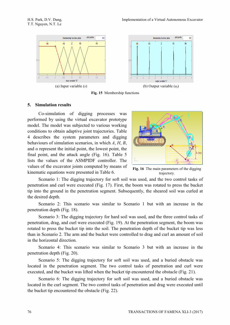
To ensure system stability, a fuzzy compensator was designed to reduce the approximation error and to eliminate chattering phenomena. The functions of the inputs and outputs are the sliding surfaces and the fuzzy gains, respectively. The membership functions of the inputs and outputs are the triangular type and the singleton type, respectively (Fig. 15). NB, NS, Z, PS, and PB denote negative big, negative small, zero, positive small, and positive big, respectively.
The defuzzification of the output is executed by the center-of-gravity method. 3
11 1 2 2 3 33
1
i ii
f
ii
wu w w w
w
, (27)
where w1, w2, and w3 are the firing strengths of rule. After obtaining the control parameters of the sliding surface and the PID controller, the fuzzy gains are determined based on the system boundary, which satisfies the Lyapunov stability theory.
TRANSACTIONS OF FAMENA XLI-3 (2017) 73

H.S. Park, D.V. Dang, Implementation of a Virtual Autonomous Excavator T.T. Nguyen, N.T. Le
(a) Obstacle in soft soil, in the penetration segment of the bucket path
(b) Obstacle in hard soil, in the penetration segment of the bucket path
(c) Obstacle in soft soil, in the curl segment of the bucket path
(d) Obstacle in hard soil, in the drag segment of the bucket path
Fig. 9 Possible positions of an obstacle
Fig. 10 Time graphs of joint actions in soft soil Fig. 11 Time graphs of joint actions in hard soil
74 TRANSACTIONS OF FAMENA XLI-3 (2017)

Implementation of a Virtual Autonomous Excavator H.S. Park, D.V. Dang, T.T. Nguyen, N.T. Le
Fig. 12 Algorithm for adjusting joint angle trajectories
(a) Input and output variables (b) Mechanical model of excavator in Simulink Fig. 13 The principle of the connection between Adams and Matlab/Simulink
Fig. 14 Proposed ASMPIDF control system in MATLAB/Simulink.
TRANSACTIONS OF FAMENA XLI-3 (2017) 75
H.S. Park, D.V. Dang, Implementation of a Virtual Autonomous Excavator T.T. Nguyen, N.T. Le
(a) Input variable (s) (b) Output variable (uf)
Fig. 15 Membership functions
5. Simulation results
Co-simulation of digging processes was performed by using the virtual excavator prototype model. The model was subjected to various working conditions to obtain adaptive joint trajectories. Table 4 describes the system parameters and digging behaviours of simulation scenarios, in which A, H, B, and α represent the initial point, the lowest point, the final point, and the attack angle (Fig. 16). Table 5 lists the values of the ASMPIDF controller. The values of the excavator joints computed by means of kinematic equations were presented in Table 6.
Fig. 16 The main parameters of the digging
trajectory. Scenario 1: The digging trajectory for soft soil was used, and the two control tasks of
penetration and curl were executed (Fig. 17). First, the boom was rotated to press the bucket tip into the ground in the penetration segment. Subsequently, the sheared soil was curled at the desired depth.
Scenario 2: This scenario was similar to Scenario 1 but with an increase in the penetration depth (Fig. 18).
Scenario 3: The digging trajectory for hard soil was used, and the three control tasks of penetration, drag, and curl were executed (Fig. 19). At the penetration segment, the boom was rotated to press the bucket tip into the soil. The penetration depth of the bucket tip was less than in Scenario 2. The arm and the bucket were controlled to drag and curl an amount of soil in the horizontal direction.
Scenario 4: This scenario was similar to Scenario 3 but with an increase in the penetration depth (Fig. 20).
Scenario 5: The digging trajectory for soft soil was used, and a buried obstacle was located in the penetration segment. The two control tasks of penetration and curl were executed, and the bucket was lifted when the bucket tip encountered the obstacle (Fig. 21).
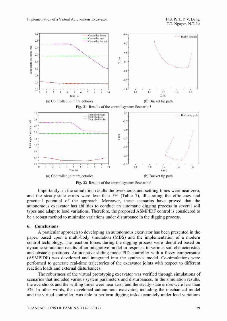
Scenario 6: The digging trajectory for soft soil was used, and a buried obstacle was located in the curl segment. The two control tasks of penetration and drag were executed until the bucket tip encountered the obstacle (Fig. 22).
76 TRANSACTIONS OF FAMENA XLI-3 (2017)

Implementation of a Virtual Autonomous Excavator H.S. Park, D.V. Dang, T.T. Nguyen, N.T. Le
Table 4 Parameter values in the simulated scenarios
Scenario The Cartesian coordinates of the trench (m) Excavator behaviour
A (x, y) H (x, y) B (x, y) α (rad) 1 (*) (1.618;-0.613) (1.481;-0. 910) (1.021;-0.478) 1.76 Penetration and curl 2 (*) (1.618;-0.613) (1.442;-0.978) (0.994;-0.520) 1.76 Penetration and curl 3 (*) (1.618;-0.614) (1.55;-0.80) (0.498;-0.483) 1.76 Penetration, drag, and curl 4 (*) (1.618;-0.614) (1.514;-0.870) (0.485;-0.487) 1.76 Penetration, drag, and curl 5(**) (1.618;-0.614) (a) 1.76 Penetration and curl 6(**) (1.618;-0.614) (1.465, -0.960) (b) 1.76 Penetration and lift
(*): without obstacle; (**): with obstacle; (a) obstacle in penetration segment; (b) obstacle in drag segment.
Table 5 Control gains of ASMPIDF
Controller Sliding surface Adaptive PID controller Fuzzy compensator k1 k2 ηp ηi ηd b Fuzzy gain
Boom joint 7 14 2e9 2e3 −10 1/1.05 3e5 Arm joint 7 14 3e8 1e4 15 1/0.9 3e4
Bucket joint 7 14 −1e7 0.1 −10 1/0.4 3e3
Table 6 Joint values
Excavator joints Scenario 1 Scenario 2 Scenario 3 Scenario 4 Scenario 5 Scenario 6
Joint 1 θ1i(rad) 0.4256 0.4256 0.4256 0.4256 0.4256 0.4256 θ1f(rad) 0.2161 0.1638 0.2859 0.2510 0.1638 0.1812
Joint 2 θ2i(rad) 1.8986 1.8986 1.8986 1.8986 1.8986 1.8986 θ2f(rad) 1.8986 1.8986 1.2000 1.2000 1.8986 1.8986
Joint 3 θ3i(rad) 2.5804 2.5804 2.5804 2.5804 2.5804 2.5804 θ3f(rad) 1.0100 1.0100 1.5377 1.5377 1.1848 1.1848
i: initial value, f: final value
Table 7 Steady state errors (%) of simulated joint trajectories
Scenario Trajectory
1 (Fig.16a)
2 (Fig.17a)
3 (Fig.18a)
4 (Fig.19a)
5 (Fig.20a)
6 (Fig.21a)
Boom joint 1.9 2.1 2 1.8 1.5 2.5 Arm joint 0.5 0.8 0.6 0.85 0.9 1.05 Bucket joint 1.9 2.1 1.96 1.98 1.8 2.0
(a) Controlled joint trajectories (b) Bucket tip path Fig. 17 Results of the control system: Scenario 1
Controlled boomControlled armControlled bucket
0 1 2 3 4 5 6 7 8 9 100.0
0.5
1.0
1.5
2.0
2.5
3.0
Join
t ang
le tra
jecto
ry (r
ad)
Time (s)0.6 0.8 1.0 1.2 1.4 1.6
-1.0
-0.9
-0.8
-0.7
-0.6
-0.5
-0.4
Y(m
)
X (m)
Bucket tip path
TRANSACTIONS OF FAMENA XLI-3 (2017) 77

H.S. Park, D.V. Dang, Implementation of a Virtual Autonomous Excavator T.T. Nguyen, N.T. Le
(a) Controlled joint trajectories (b) Bucket tip path Fig. 18 Results of the control system: Scenario 2
(a) Controlled joint trajectories (b) Bucket tip path Fig. 19 Results of the control system: Scenario 3
(a) Controlled joint trajectories (b) Bucket tip path Fig. 20 Results of the control system: Scenario 4
0 1 2 3 4 5 6 7 8 9 100.0
0.5
1.0
1.5
2.0
2.5
3.0
Join
t ang
le tr
ajec
tory
(rad
)
Time (s)
Controlled boomControlled armControlled bucket
0.6 0.8 1.0 1.2 1.4 1.6-1.0
-0.9
-0.8
-0.7
-0.6
-0.5
-0.4
Y (m
)
X (m)
Bucket tip path
0 1 2 3 4 5 6 7 8 9 100.0
0.5
1.0
1.5
2.0
2.5
3.0
Join
t ang
le tr
ajec
tory
(rad
)
Time (s)
Controlled boomControlled armControlled bucket
0 2 4 6 8 100.0
0.5
1.0
1.5
2.0
2.5
3.0
Join
t ang
le tr
ajec
tory
(rad
)
Time (s)
Controlled boomControlled armControlled bucket
0.4 0.6 0.8 1.0 1.2 1.4 1.6-1.0
-0.9
-0.8
-0.7
-0.6
-0.5
-0.4
Y (m
)
X (m)
Bucket tip path
78 TRANSACTIONS OF FAMENA XLI-3 (2017)
Implementation of a Virtual Autonomous Excavator H.S. Park, D.V. Dang, T.T. Nguyen, N.T. Le
(a) Controlled joint trajectories (b) Bucket tip path Fig. 21 Results of the control system: Scenario 5
(a) Controlled joint trajectories (b) Bucket tip path Fig. 22 Results of the control system: Scenario 6
Importantly, in the simulation results the overshoots and settling times were near zero, and the steady-state errors were less than 5% (Table 7), illustrating the efficiency and practical potential of the approach. Moreover, these scenarios have proved that the autonomous excavator has abilities to conduct an automatic digging process in several soil types and adapt to load variations. Therefore, the proposed ASMPIDF control is considered to be a robust method to minimize variations under disturbance in the digging process.
6. Conclusions A particular approach to developing an autonomous excavator has been presented in the
paper, based upon a multi-body simulation (MBS) and the implementation of a modern control technology. The reaction forces during the digging process were identified based on dynamic simulation results of an integrative model in response to various soil characteristics and obstacle positions. An adaptive sliding-mode PID controller with a fuzzy compensator (ASMPIDF) was developed and integrated into the synthesis model. Co-simulations were performed to generate real-time trajectories of the excavator joints with respect to different reaction loads and external disturbances.
The robustness of the virtual prototyping excavator was verified through simulations of scenarios that included various system parameters and disturbances. In the simulation results, the overshoots and the settling times were near zero, and the steady-state errors were less than 5%. In other words, the developed autonomous excavator, including the mechanical model and the virtual controller, was able to perform digging tasks accurately under load variations
0 1 2 3 4 5 6 7 8 9 100.0
0.4
0.8
1.2
1.6
2.0
2.4
2.8
3.2Jo
int a
ngle
traj
ecto
ry (r
ad)
Time (s)
Controlled boomControlled armControlled bucket
0.8 1.0 1.2 1.4 1.6-1.0
-0.9
-0.8
-0.7
-0.6
-0.5
-0.4
Y (m
)
X (m)
Bucket tip path
0 1 2 3 4 5 6 7 8 9 100.0
0.4
0.8
1.2
1.6
2.0
2.4
2.8
3.2
Join
t ang
le tr
ajec
tory
(rad
)
Time (s)
Controlled boomControlled armControlled bucket
0.8 1.0 1.2 1.4 1.6-1.0
-0.9
-0.8
-0.7
-0.6
-0.5
-0.4
Y (m
)
X (m)
Bucket tip path
TRANSACTIONS OF FAMENA XLI-3 (2017) 79
H.S. Park, D.V. Dang, Implementation of a Virtual Autonomous Excavator T.T. Nguyen, N.T. Le
and when external disturbances occur. Therefore, use of the proposed approach could improve digging efficiency, decrease workplace accidents, and increase the excavator lifespan.
Although simulation models are useful, physical experiments to verify the simulation and optimization results are indispensable. Thus, the physical experimentation and verification will be the subject of further work.
ACKNOWLEDGMENTS This work was supported by the ICT R&D program of MSIP/IITP. [B0101-17-1081,
Development of ICT based software platform and service technologies for medical 3D printing applications]
REFERENCES [1] Carlos Balaguer, Mohamed Abderrahim, Trends in Robotics and Automation in Construction: Book of
Robotics and Automation in Construction, 2008. [2] A. Reece, The Fundamental Equation of Earth Moving Mechanics, 1964. [3] Tan, ChooPar Par, Zweiri, H. Yahya, Althoefer, A. Kaspar, Seneviratne, Lakmial D,Online Soil-bucket
Interaction Identification for Autonomous Excavation,Proceedings of IEEE International Conference on Robotics and Automation, pp. 3576-3581, 2005.
[4] Althoefer Kaspar, Tan ChooPar Par, Zweiri Yahya H., Seneviratne Lakmial D., Hybrid Soil Parameter Measurement and Estimation Scheme for Excavation Automation, IEEE Transactions on Instrumentation and Measurement, Vol. 58, No. 10, pp. 3633-3641, 2009. https://doi.org/10.1109/TIM.2009.2018699
[5] Singh, Sanjiv Sanjiv, Simmons, Reid G.,Task Planning for Robotic Excavation,Proceedings of theIEEE/RSJ International Conference on Intelligent Robots and Systems, pp. 1284-1291, 1992. https://doi.org/10.1109/IROS.1992.594551
[6] Soon-Young Yong, Jin, Sung-Min Yang and Soon-Kwang Kwon,Remote control system of industrial field robot,IEEE International Conference on Industrial Informatics, pp. 442-447, 2008.
[7] Hongnian Yu, Yang Liu, Mohammad Shahidul Hasan,Review of modelling and remote control for excavators,Int. J. Advanced Mechatronic System, Vol. 2, No. 1-2, pp. 68-80, 2010. https://doi.org/10.1504/IJAMECHS.2010.030850
[8] Q. P. Ha, D.C. Rye, H.F. Durrant-Whyte M. Santos,Global control for robotic excavation using fuzzy logic and statecharts,Proceedings of the 17th ISARC, pp. 1-7, 2000.
[9] Paul J.A, Lever, Fei-Yue Wang, Deqian Chen,A fuzzy control system for an automated mining excavator,Proceedings of the IEEE International Conference on Robotics and Automation, vol. 4, pp. 3284-3289, 1994.
[10] Y. Altintas, C. Brecher, M. Weck, S. Witt,Virtual Machine Tool,CIRP Annals-Manufacturing Technology, vol. 54, no. 2, pp. 115-138, 2005. https://doi.org/10.1016/S0007-8506(07)60022-5
[11] Weihang Zhu, Yuan-Shin Lee, Five-axis pencil-cut planning and virtual prototyping with 5-DOF haptic interface, Computer-Aided Design, Vol. 36, No. 13, Pp. 1295–1307, 2004. https://doi.org/10.1016/j.cad.2004.01.013
[12] Zoran Pandilov, Andrzej Milecki, Amadeusz Nowak, Filip Górski, Damian Grajewski Damir Ciglar, Tihomir Mulc, Miho Klaić, Virtual Modelling and Simulation of a CNC Machine Feed Drive System, Transactions of FAMENA, Vol.39, No.4. pp. 37-54, 2016.
[13] Nataša A. Kablar, Vladimir M. Kvrgić, Dragutin Lj. Debeljković, Robust Stability of Singularly Impulsive Dynamical Systems, Transactions of FAMENA,Vol.39, No.2, pp. 23-32, 2015.
Submitted: 11.8.2016 Accepted: 09.3.2017
Hong-Seok Park Duc-Viet Dang Trung-Thanh Nguyen Ngoc-Tran Le School of Mechanical and Automotive Engineering, University of Ulsan, 93 Daehak-ro, Nam-gu, Ulsan, South-Korea, 44610 E-mail: [email protected] TEL: +82-52-259-2294 FAX: +82-52-259-1680
80 TRANSACTIONS OF FAMENA XLI-3 (2017)