implementation of a fuzzy logic-based embedded system for ... · fuzzy logic systems g. oltean...
TRANSCRIPT

Fuzzy Logic Systems G. Oltean
Implementation of a Fuzzy Logic-Based Embedded System for Engine RPM
Control
(Speed Control)

Fuzzy Logic Systems G. Oltean
Introduction
➢implements an embedded system for the
Engine RPM control based on a
development board
➢developed around an Arduino Mega board
➢fuzzy logic system as controller
➢offers an easy understanding of the main
concepts regarding embedded systems

Fuzzy Logic Systems G. Oltean
System implementationBlock diagram
Fuzzy Logic Systems G. Oltean
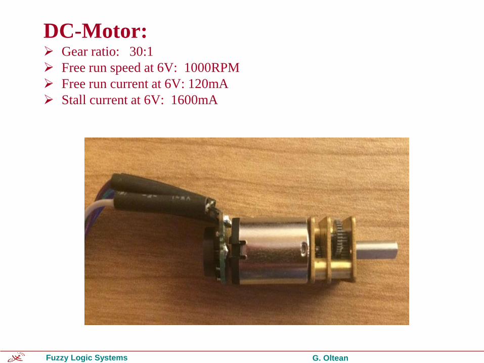
DC-Motor:➢ Gear ratio: 30:1
➢ Free run speed at 6V: 1000RPM
➢ Free run current at 6V: 120mA
➢ Stall current at 6V: 1600mA

Fuzzy Logic Systems G. Oltean
Hall Effect Sensor
The Hall effect:
❖ the production of a voltage difference (the Hall voltage) across an electrical conductor:
✓ transverse to an electric current in the conductor
✓ an applied magnetic field perpendicular to the current.
[What is Hall Effect and How Hall Effect Sensors Work,
https://www.youtube.com/watch?v=wpAA3qeOYiI]
B
Fuzzy Logic Systems G. Oltean
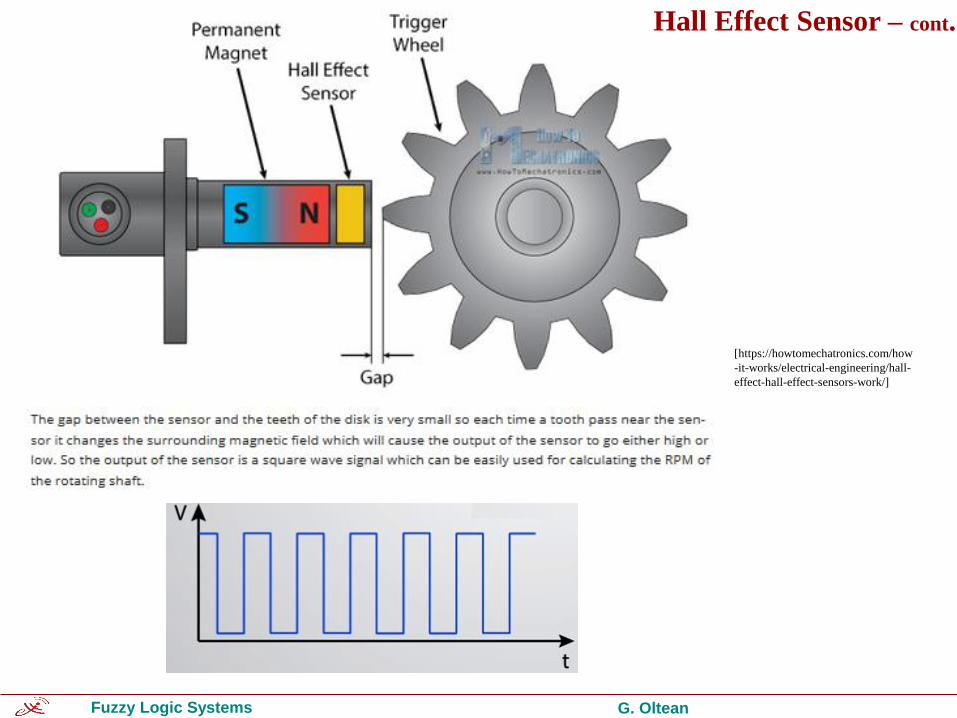
Hall Effect Sensor – cont.
[https://howtomechatronics.com/how
-it-works/electrical-engineering/hall-
effect-hall-effect-sensors-work/]

Fuzzy Logic Systems G. Oltean
Quadrature Encoder:
• Six pole magnetic disk +PCB
• Dual Channel
• 12 counts/revolution
• 2.8V -18V
Output signal
of the encoder

Fuzzy Logic Systems G. Oltean
Motor Driver:
• L298 - Dual Full Bridge Driver (H bridge)
• Middle class
• 2 Motors
• Sensors power supply

Fuzzy Logic Systems G. Oltean
Motor Driver:
• L298 - Dual Full Bridge Driver (H bridge)
• Middle class
• 2 Motors
• Sensors power supply
How the RPM can be controlled?
Fuzzy Logic Systems G. Oltean
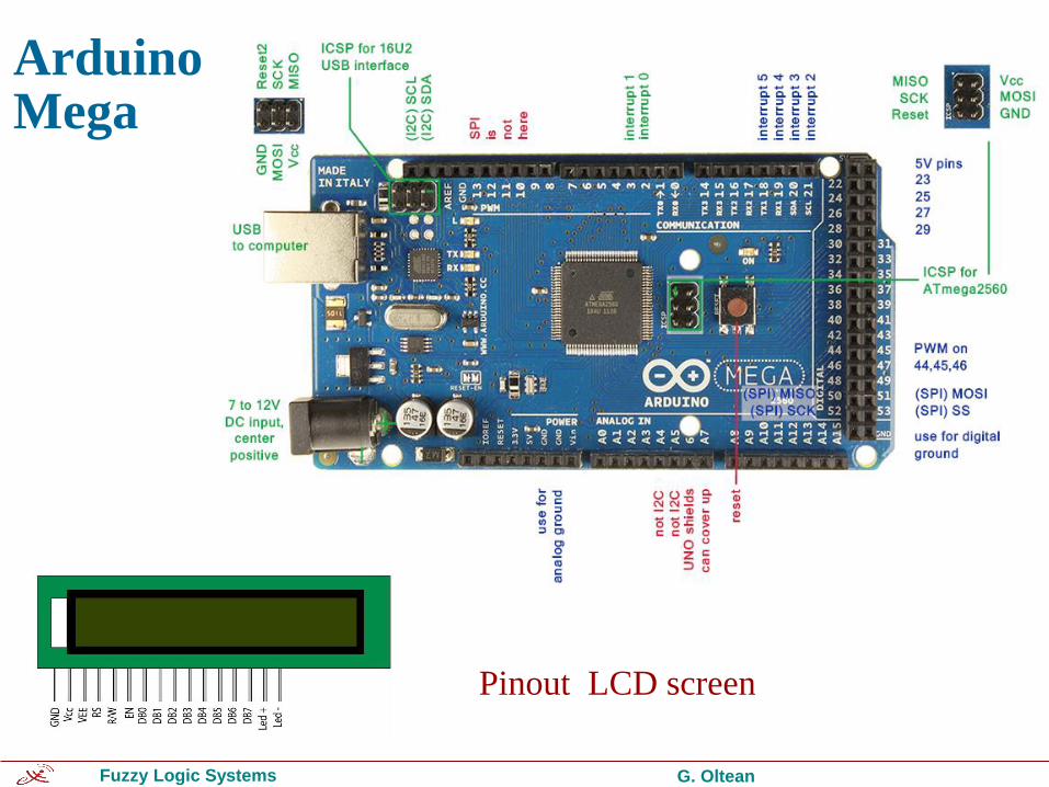
ArduinoMega
Pinout LCD screen
Fuzzy Logic Systems G. Oltean
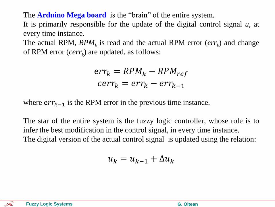
The Arduino Mega board is the “brain” of the entire system.
It is primarily responsible for the update of the digital control signal u, at
every time instance.
The actual RPM, RPMk is read and the actual RPM error (errk) and change
of RPM error (cerrk) are updated, as follows:
ⅇ𝑟𝑟𝑘 = 𝑅𝑃𝑀𝑘 − 𝑅𝑃𝑀𝑟𝑒𝑓
𝑐ⅇ𝑟𝑟𝑘 = ⅇ𝑟𝑟𝑘 − ⅇ𝑟𝑟𝑘−1
where ⅇ𝑟𝑟𝑘−1 is the RPM error in the previous time instance.
The star of the entire system is the fuzzy logic controller, whose role is to
infer the best modification in the control signal, in every time instance.
The digital version of the actual control signal is updated using the relation:
𝑢𝑘 = 𝑢𝑘−1 + Δ𝑢𝑘
Fuzzy Logic Systems G. Oltean
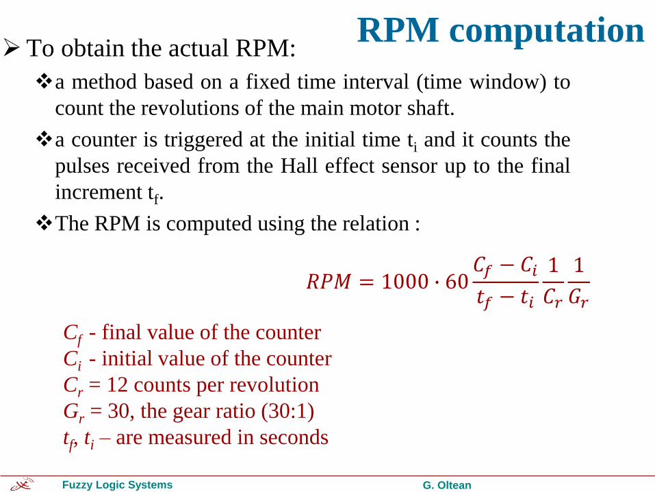
RPM computation➢To obtain the actual RPM:
❖a method based on a fixed time interval (time window) to
count the revolutions of the main motor shaft.
❖a counter is triggered at the initial time ti and it counts the
pulses received from the Hall effect sensor up to the final
increment tf.
❖The RPM is computed using the relation :
Cf - final value of the counter
Ci - initial value of the counter
Cr = 12 counts per revolution
Gr = 30, the gear ratio (30:1)
tf, ti – are measured in seconds
𝑅𝑃𝑀 = 1000 ∙ 60𝐶𝑓 − 𝐶𝑖𝑡𝑓 − 𝑡𝑖
1
𝐶𝑟
1
𝐺𝑟

Fuzzy Logic Systems G. Oltean
RPM computation
Cf - final value of the counter
Ci - initial value of the counter
Cr = 12 counts per revolution
Gr = 30, the gear ratio (30:1)
tf, ti – are measured in milliseconds
𝑅𝑃𝑀 = 1000 ∙ 60𝐶𝑓 − 𝐶𝑖
𝑡𝑓 − 𝑡𝑖
1
𝐶𝑟
1
𝐺𝑟

Fuzzy Logic Systems G. Oltean
The Fuzzy Logic Controller
➢ first-order Takagi-Sugeno
➢ two inputs errFls and cerrFls
➢ one output ΔuFls
Fuzzy sets for the inputs Fuzzy sets for the output

Fuzzy Logic Systems G. Oltean
errFls
cerrFls Neg Zero Pos
Neg N N Z
Zero N Z P
Pos Z P P
Rule base of the
fuzzy logic system
Block diagram of the fuzzy logic controller

Fuzzy Logic Systems G. Oltean
The defuzzification method, used to transform the partial output fuzzy sets resulted from the inference process into a crisp value is the weighted average method.

Fuzzy Logic Systems G. Oltean
Control surface of the fuzzy logic controller
ou
tpu
t
cErr
Err

Fuzzy Logic Systems G. Oltean
Control Circuit
Fuzzy
logic
system cerr + _
+ _
RPM ref
z
1
ΔuFls
- +
z
1
u
RPM
errFls
cerrFls
0
255 -1
+1
-1
+1 su
err se
sc
Δu Motor
Driver
DC
Motor ua

Fuzzy Logic Systems G. Oltean
System setup

Fuzzy Logic Systems G. Oltean
Experimental resultsRPM from 0 to 1000
rise time = 8.8 s;
max. positive error = 5 rpm ;
max. negative error = 5rpm;
RPM from 1000 to 500
fall time = 6.75 s;
max. positive error = 6 rpm ;
max. negative error = 9rpm;
RPM from 500 to 750
rise time = 4.75 s;
max. positive error = 8 rpm ;
max. negative error = 6rpm;
RPM from 750 to 0
fall time = 6.5 s;

Fuzzy Logic Systems G. Oltean

Fuzzy Logic Systems G. Oltean
To drastically decrease the time response of the control system,
the control strategy should be slightly modified.
Because the control characteristic of the DC motor driven by
the H-Bridge is almost liner, when a large variation of the motor
speed is required (larger than 60 rpm), the control signal is not
determined by the fuzzy logic system, but it is estimated by a
simple linear interpolation, that acts as a course adjustment of
the control signal.
Then, the fuzzy logic system regains its role for the fine
adjustment of the speed.
Decreasing the time response

Fuzzy Logic Systems G. Oltean

Fuzzy Logic Systems G. Oltean
Tracking mode operation: RPM tracks the temperature variation

Fuzzy Logic Systems G. Oltean
Duty Cycle
23%
Low Speed
55%
Medium Speed
90%
High Speed