implementation of 802.15.4 wireless sensor...
TRANSCRIPT
International Journal of Smart Device and Appliance Vol.2, No.1 (2014)
16
Implementation of 802.15.4 Wireless Sensor Network in Real-time Monitoring and Control System for Green House
Jaypal Baviskar, Afshan Mulla, Amol Baviskar, Jeet Desai Department of Electronics and Telecommunication, Veermata Jijabai Technological
Institute, Mumbai 400039, India Department of Electronics Engineering, Universal College Of Engineering, Thane-
421302, India [email protected], [email protected], [email protected],
Abstracta In order to meet the increasing need for quality conscience crops and to utilize the resources efficiently, the concept of Greenhouse was introduced. It assists in accurate monitoring and controlling of various parameters, in order to nurture healthy crops. In this paper efforts are made to acknowledge the problems associated with maintaining precise environmental conditions, and to implement a sophisticated system to supervise the real-time monitoring and controlling operation inside the Greenhouse. The necessity for an Automated System deploying wireless communication and remote sensing is considered. This paper illustrates the implementation of a WSN (Wireless Sensor Network) based embedded system supported by ZigBee network (over IEEE 802.15.4) for organizing Greenhouse parameters. The establishment of various topologies supported by ZigBee network viz. Star topology & Mesh Topology are illustrated. It also demonstrates the real time supervision of parameters such as temperature, humidity as well as the total power consumption of the system, along with appropriate sensors. With the help of a PC based GUI application developed on Java platform graphs are plotted to evaluate the system performance.
Keywords: Greenhouses, Real time monitoring, WSN, Embedded system, ZigBee
(IEEE 802.15.4), sensors, temperature, humidity, power consumption, Topology, GUI. 1. INTRODUCTION
Due to the research and advancement in the field of automation, it has facilitated development in wireless communication. Automation along with the use of Wireless Sensor Networks (WSNs) have superseded the traditional manual control systems hence gaining popularity in industrial, domestic
as well as in agricultural sector. This has led to an integrated way leading to new solutions, better performance and an absolute system. In the field of automation WSNs have revolutionized [1] the design of emergiang embedded systems in terms of various factors viz. scalability, mobility, power consumption etc.
A wireless sensor network (WSN) consists of spatially distributed autonomous sensors to cooperatively monitor the physical or environmental conditions, such as temperature, vibration, pressure, motion etc. As stated by Palanisamy et al. in [2] the unique characteristics of WSNs are:
• Can store and harvest limited power • Ability to withstand callous environmental conditions • Ability to cope with node failures • Mobility of nodes is possible • Dynamic network topology • Heterogeneity of nodes • Large scale deployment
International Journal of Smart Device and Appliance Vol.2, No.1 (2014)
17
• Unattended operation and self governing ability • Node capacity is scalable, only limited by bandwidth of gateway node.
Since environmental diversity exists and there are changes in the ecological conditions from region to region, there is a variety in the cultivation of crops. The main objective of the green house is to breed plants in any particular region independent of its existing environmental conditions. For this purpose an automatic embedded system is required to facilitate the smooth maneuver of cultivation. Ral Aquino-Santos [3] et al. have discussed the applications of WSN in greenhouse control environment and stated it can be a cost effective option for development of the greenhouse control system.
The detailed comparative study [4] of the different short- range wireless protocols viz. Bluetooth (over IEEE 802.15.1), UWB (over IEEE 802.15.3), ZigBee (over IEEE 802.15.4) and Wi-Fi (over IEEE 802.11a/b/g), it is found that ZigBee is an efficient protocol in field of automation. Being a controlling and a monitoring system our proposed model [5] is implemented with ZigBee protocol. It consists of two modules i.e. one is user side module in which the transceiver is connected to the user PC to control the various green house appliances remotely and the other is green house side module to which sensors are interfaced. It monitors all the parameters, fetches the real time sensed value and depicts the same on LCD display.
This paper is organized as follows; Section II provides the details regarding the ZigBee protocol and its super frame structure whereas our proposed system design is discussed in Section III. Section IV elaborates the network establishment using ZigBee protocol in detail. Section V illustrates implementation of ZigBee technology in Greenhouse supporting two architectures viz. Star and Mesh Architecture. Section VI presents the result analysis and outcome of the system and the final Section presents the conclusion of the paper. 2. ZIGBEE PROTOCOL
ZigBee standard (IEEE 802.15.4) is formed by the ZigBee Alliance Company in 2002.Though the ZigBee standard is formed in 2002 but the complete ZigBee protocol specifications were ratified in December 2004 [6]. It is a low data rate WPAN (LR-WPAN) standard which provides data rate up to 250 Kbps in the global 2.4-GHz Industrial, Scientific, Medical (ISM) band.
A. Features of ZigBee
ZigBee is self-configuring, self-healing system of redundant and low-power nodes [8] has various unique features which some of them are as follow:
• Ultra low power consumption and scalability [9]
• Supports star, mesh and cluster tree topologies
• Self-organized, multi-hop, and reliable mesh networking[10]
• Provide long battery life
B. ZigBee Protocol stack
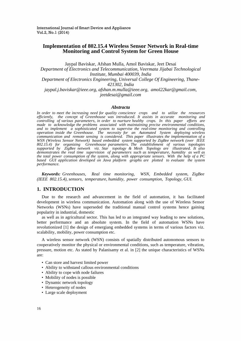
ZigBee has layered architecture shown in figure 1.It uses the IEEE 802.15.4 PHY and MAC layers to provide reliable wire- less data transfer. The ZigBee Alliance specifies the Logical
International Journal of Smart Device and Appliance Vol.2, No.1 (2014)
18
Network, Security and Application Software to complete the communication suite. PHY layer performs modulation (Offset Quadrature Phase Shift Keying (OQPSK)) and transmits the packets. Similarly on receiver side it receives the packet and performs demodulation. [11]. MAC layer uses Carrier Sense Multiple Access- Collision Avoidance(CSMA-CA) technique for accessing the Network. Network layer provides network configuration, message routing [11] and manages devices in the network. Further the interoperability and inter compatibility between similar products from different manufacturers are provided by ZigBee profiles defined in application layer [7].
Figure 1. ZigBee protocol stack
C. ZigBee Super frame structure
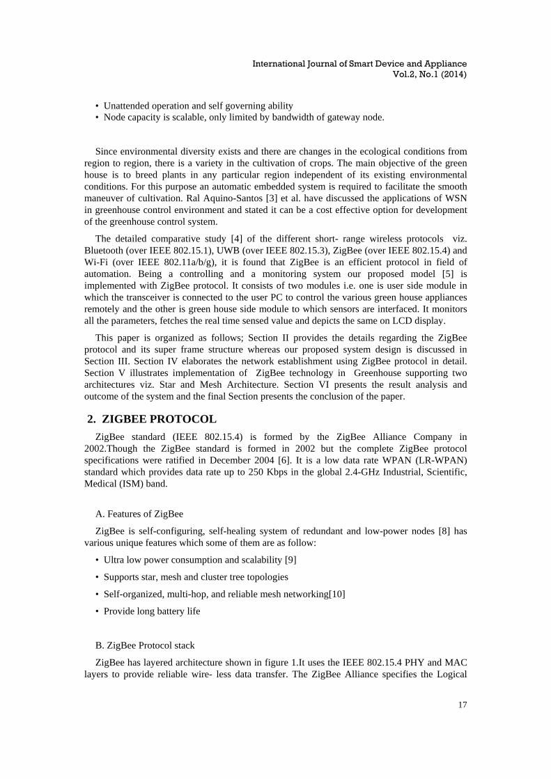
In hard real time application system it is always preferable to implement centralize access protocol type instead of random access such as CSMA/CA as missing a single deadline causes serious consequences [12]. Hence 802.15.4 can be operated in an optional super frame mode which is suitable for hard real time application, which requires dedicated bandwidth to achieve low latency [11]. such application should get some dedicated bandwidth and guaranteed time slots on deterministic basis instead of probabilistic one. This is possible in Contention Free Period (CFP) only. PAN coordinator can allocate such slots (maximum 7) known as guaranteed time slots (GTSs) which forms the CFP. Sometimes channel access can be denied because of low priority or unavailability of GTSs. It can be resolved using implementation of CSMA/CA in Contention Access period (CAP). Beacon frame is trans- mitted at the starting of each super frame (refer figure 2) for synchronization purpose. Along with the beacon frame there are other types of frame such as data, acknowledgment and MAC command which plays very crucial role while network establishment.
Figure 2. IEEE 802.15.4 super frame structure
International Journal of Smart Device and Appliance Vol.2, No.1 (2014)
19
D. ZigBee Devices
Devices used in ZigBee protocol are categorized on the basis of their functionality [6] as follows:
• Full-function Device (FFD): The FFD has full functionality and it can communicate with other FFDs and RFDs. It can therefore act as a PAN coordinator, a coordinator and a router or even as a RFD.
• Reduced-function Device (RFD): The RFD can communicate only with the FFD viz. network coordinator or router. As their functionality is governed by these coordinators, communication between two RFDs cannot be established.
Among all the PAN devices, it is only the PAN coordinator that has best computational resources. It is the only network element which is able to establish communication with other networks in the vicinity. 3. SYSTEM DESIGN
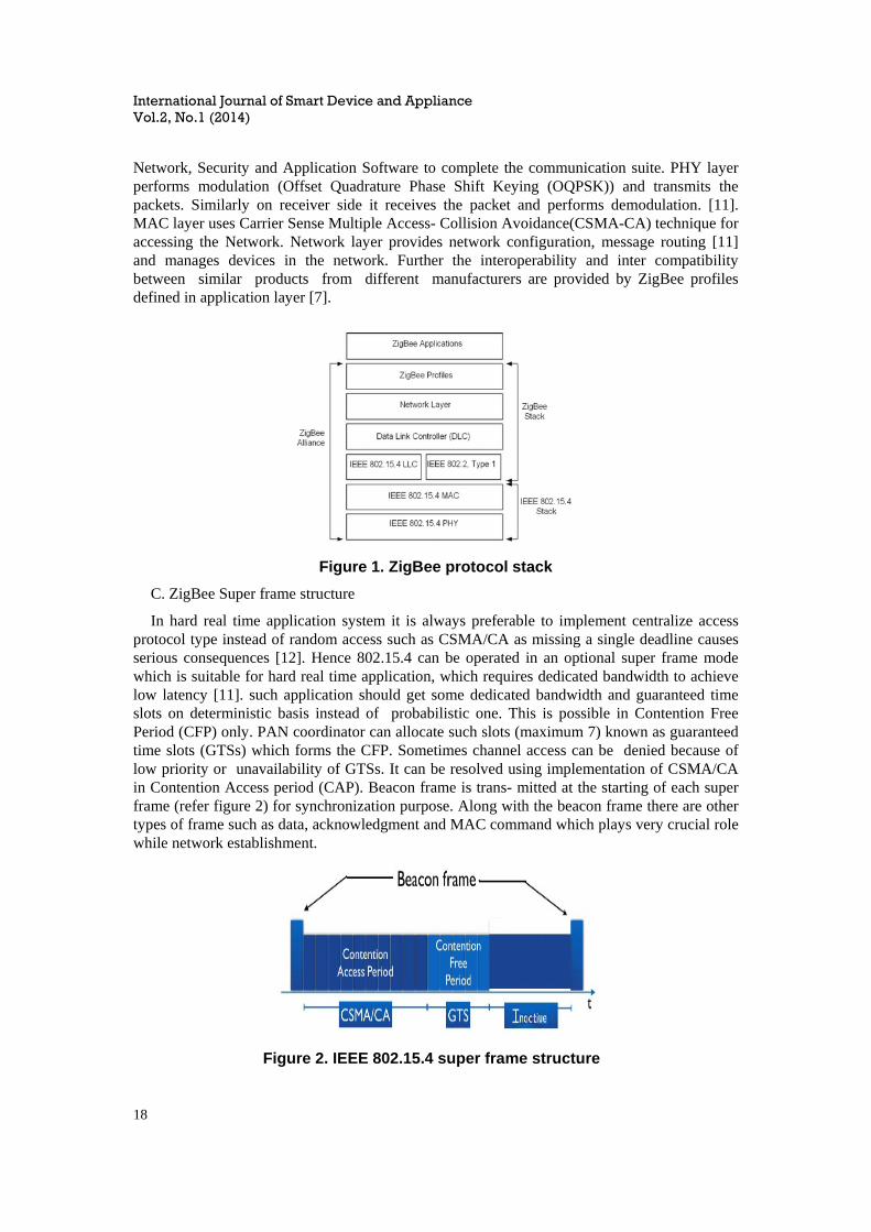
Our designed system is implemented with ZigBee protocol. It mainly consists of two systems viz. Portable Controller Node (PCN) system and the Sensor and actuator Node (SAN) system. The block diagram is as shown in figure 3 below:
Figure 3. Block diagram of proposed system
A. Portable Controller Node (PCN) system
PCN system mainly consists of user laptop/PC and ZigBee transceiver module interfaced with PC via UART (Universal Asynchronous Receiver/Transmitter) port. Module of XBee Series2 of Digi Inc. [13] is used which is configured as PAN coordinator API. It transmits user control commands serving as Controller node. The XBee modules are programmed using X-CTU software in Application Programming Interface (API) mode [14] which helps to construct a real wireless network. A Java based GUI application is developed on PC which facilitates the real time monitoring of various green house parameters using sensor nodes as well as remote control of appliances using actuator nodes.
International Journal of Smart Device and Appliance Vol.2, No.1 (2014)
20
B. Sensor and Actuator Node (SAN) system
Both PCN and SAN systems are wirelessly linked by ZigBee with star topology. If green house area and appliances to be controlled are far away then the sensor and actuator node can be implemented separately, whereas they can be integrated as one node if distance is less in SAN system.
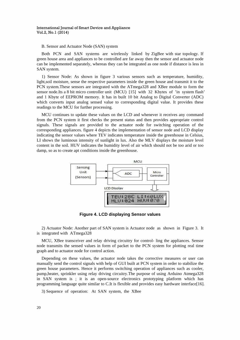
1) Sensor Node: As shown in figure 3 various sensors such as temperature, humidity, light,soil moisture, sense the respective parameters inside the green house and transmit it to the PCN system.These sensors are integrated with the ATmega328 and XBee module to form the sensor node.Its a 8 bit micro controller unit (MCU) [15] with 32 Kbytes of ’in system flash’ and 1 Kbyte of EEPROM memory. It has in built 10 bit Analog to Digital Converter (ADC) which converts input analog sensed value to corresponding digital value. It provides these readings to the MCU for further processing.
MCU continues to update these values on the LCD and whenever it receives any command from the PCN system it first checks the present status and then provides appropriate control signals. These signals are provided to the actuator node for switching operation of the corresponding appliances. figure 4 depicts the implementation of sensor node and LCD display indicating the sensor values where TEV indicates temperature inside the greenhouse in Celsius, LI shows the luminous intensity of sunlight in lux. Also the MLV displays the moisture level content in the soil. HUV indicates the humidity level of air which should not be too arid or too damp, so as to create apt conditions inside the greenhouse.
Figure 4. LCD displaying Sensor values
2) Actuator Node: Another part of SAN system is Actuator node as shown in Figure 3. It is integrated with ATmega328
MCU, XBee transceiver and relay driving circuitry for control- ling the appliances. Sensor node transmits the sensed values in form of packet to the PCN system for plotting real time graph and to actuator node for control action.
Depending on these values, the actuator node takes the corrective measures or user can manually send the control signals with help of GUI built at PCN system in order to stabilize the green house parameters. Hence it performs switching operation of appliances such as cooler, pump,heater, sprinkler using relay driving circuitry.The purpose of using Arduino Atmega328 in SAN system is ; it is an open-source electronics prototyping platform which has programming language quite similar to C.It is flexible and provides easy hardware interface[16].
3) Sequence of operation: At SAN system, the XBee

International Journal of Smart Device and Appliance Vol.2, No.1 (2014)
21
transceiver module is interfaced with the Arduino MCU and is configured as ZigBee Router in API mode. The process flow of operation at SAN can be summarized as follow:
• Real time status of green house parameters is updated and transmitted to PCN system periodically by sensor node.
• On the basis of real time monitoring user can send the control commands to actuator node.
• Actuator Node receives control commands in form of packets from PCN system via ZigBee transceivers. These commands are processed by MCU of actuator node.
• MCU checks the present status, threshold value and compares them to take an appropriate action.
• Then actuator node performs the switching operation of appliances if its necessary.
• Present status of the appliances is retransmitted back to the PCN system and the GUI window is updated automatically. 4. ESTABLISHMENT OF ZIGBEE NETWORK
In our system communication between PCN and SAN sys- tem is established by ZigBee network. PCN side Transceiver is connected to the user PC via BAFO cable and is configured as the network PAN Coordinator. Each ZigBee network should have at least one PAN Coordinator which is unique in the network. It performs various operations such as structuring the network, establishing an addressing scheme, keeping the ad- dressing tables. In order to establish network along with PAN coordinator at least one ZigBee Router(in case of point to point configuration) or two or more, ZigBee routers and ZigBee End Devices (in case of point to multi point configuration) are required. We have configured PCN side Transceiver as PAN coordinator which exchanges the commands with SAN side Routers.
We established the network using star topology where PCN is a central controller node. Whenever system is powered on first time, PCN chooses unused PAN Identifier and becomes the PAN coordinator. It starts establishing the network by broadcasting the beacon frames to sensor and actuator nodes (1st phase) as shown in Figure 5 [17]. These nodes can either be ZigBee End Device (RFD) or ZigBee Router (FFD). If these nodes want to join the network, they can send the request to PCN (2nd phase).Then PCN will add these nodes as child nodes in its neighbor list and will send the response in 3rd phase. In the 4th phase sensor and actuator nodes will add PCN as parent node in their neighbor list and will return the acknowledgment to PCN.
Figure 5. Establishment Of ZigBee Network

International Journal of Smart Device and Appliance Vol.2, No.1 (2014)
22
A. Configuration of XBee modules
The configuration of XBee modules is the initial step while establishing the ZigBee Network. XBee-S2 modules are used in our system which operate in two modes; Transparent (AT mode) and API mode. API mode is enabled in which modules are configured as PAN coordinator, Router or End Device by using X-CTU software. Configuration of XBee transceiver as PAN coordinator and as Router is elaborated further.
1) ZigBee PAN Coordinator: Configuration of XBee transceiver as PAN coordinator is as depicted in Figure 6. The PAN ID must be identical for all the XBee radios, as in this system it is 1234. Also the Baud rate should be same; default baud rate being 9600 is modified as 115200 uses X-CTU API mode. For operating the Coordinator in Broadcasting mode its DL - Destination Address Low has to be FFFF for Router, DL address is set to 0 which is the default DL Address for a Coordinator.
Figure 6. Configuring XBee transceiver as PAN coordinator
2) ZigBee Router : Configuration of XBee transceiver as a Router is as depicted in Figure 7.
Figure 7. Configuring XBee transceiver as ZigBee Router
International Journal of Smart Device and Appliance Vol.2, No.1 (2014)
23
The configuration procedure almost remains same for Coordinator and Router. But this time, in selection window instead of selecting the node as a Coordinator, select it as a Router and then press Write (refer Figure 7). Then, read operation is followed to get the configuration. Further the address of the Coordinator has to be programmed in router so that in initial stage it would be able to connect to appropriate Coordinator. This can be done by setting the DH - Destination Address High and DL - Destination Address Low with the serial number taken from the Coordinator. After this amendments press Write, to configure the node as router.
The procedure which is explained in above sections has to be followed while configuring the XBee modules as Pan coordinator and Router in API mode with same Personal Network ID (PAN ID).
B. Range of the established network
Established network can be characterized by the Network span (range) and the implemented topology. The range of the network depends on environmental conditions, network topology and range specifications of implemented transceiver module. Adverse environmental conditions reduces the Re- ceived Signal Strength Indicator (RSSI) value and weaken the signal. Increase in the transmitted Signal Power can overcome the adverse effect, but it will hamper the ultra low power consumption feature of the ZigBee protocol.
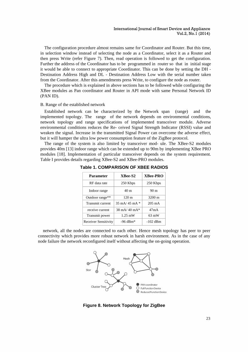
The range of the system is also limited by transceiver mod- ule. The XBee-S2 modules provides 40m [13] indoor range which can be extended up to 90m by implementing XBee PRO modules [18]. Implementation of particular transceiver depends on the system requirement. Table I provides details regarding XBee-S2 and XBee-PRO modules.
Table 1. COMPARISON OF XBEE RADIOS
Parameter XBee-S2 XBee-PRO
RF data rate 250 Kbps 250 Kbps
Indoor range 40 m 90 m
Outdoor range** 120 m 3200 m
Transmit current 35 mA/ 45 mA * 205 mA
receive current 38 mA/ 40 mA* 47mA
Transmit power 1.25 mW 63 mW
Receiver Sensitivity -96 dBm* -102 dBm
network, all the nodes are connected to each other. Hence mesh topology has peer to peer connectivity which provides more robust network in harsh environment. As in the case of any node failure the network reconfigured itself without affecting the on-going operation.
Figure 8. Network Topology for ZigBee
International Journal of Smart Device and Appliance Vol.2, No.1 (2014)
24
5. ZIGBEE ARCHITECTURE IMPLEMENTATION FOR GREEN HOUSE
As described in above section, one of the factor which influence the network span is the topology of the network. In broad manner, each topology represents the architecture to be implemented which is categorized as; Star architecture and Mesh architecture. For small scale application and limited network span star architecture is suitable. Hence it is implemented in our system as it is competent for controlling one green house. The network span can be increased further with the use of mesh architecture.
A. Star Architecture Implementation
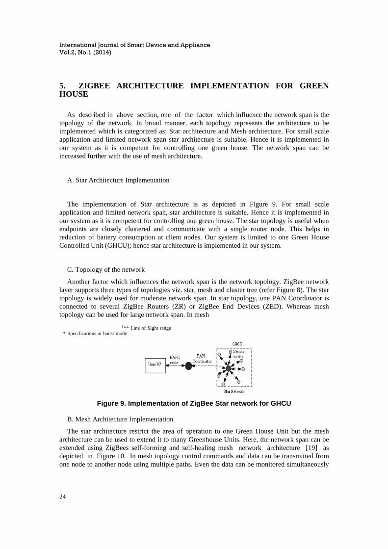
The implementation of Star architecture is as depicted in Figure 9. For small scale application and limited network span, star architecture is suitable. Hence it is implemented in our system as it is competent for controlling one green house. The star topology is useful when endpoints are closely clustered and communicate with a single router node. This helps in reduction of battery consumption at client nodes. Our system is limited to one Green House Controlled Unit (GHCU); hence star architecture is implemented in our system.
C. Topology of the network
Another factor which influences the network span is the network topology. ZigBee network layer supports three types of topologies viz. star, mesh and cluster tree (refer Figure 8). The star topology is widely used for moderate network span. In star topology, one PAN Coordinator is connected to several ZigBee Routers (ZR) or ZigBee End Devices (ZED). Whereas mesh topology can be used for large network span. In mesh
1 ** Line of Sight range * Specifications in boost mode
Figure 9. Implementation of ZigBee Star network for GHCU
B. Mesh Architecture Implementation
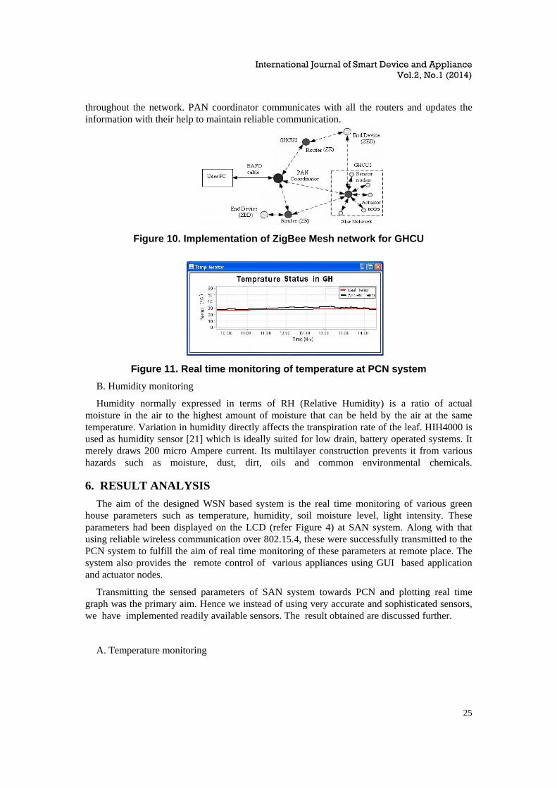
The star architecture restrict the area of operation to one Green House Unit but the mesh architecture can be used to extend it to many Greenhouse Units. Here, the network span can be extended using ZigBees self-forming and self-healing mesh network architecture [19] as depicted in Figure 10. In mesh topology control commands and data can be transmitted from one node to another node using multiple paths. Even the data can be monitored simultaneously
International Journal of Smart Device and Appliance Vol.2, No.1 (2014)
25
throughout the network. PAN coordinator communicates with all the routers and updates the information with their help to maintain reliable communication.
Figure 10. Implementation of ZigBee Mesh network for GHCU
Figure 11. Real time monitoring of temperature at PCN system
B. Humidity monitoring
Humidity normally expressed in terms of RH (Relative Humidity) is a ratio of actual moisture in the air to the highest amount of moisture that can be held by the air at the same temperature. Variation in humidity directly affects the transpiration rate of the leaf. HIH4000 is used as humidity sensor [21] which is ideally suited for low drain, battery operated systems. It merely draws 200 micro Ampere current. Its multilayer construction prevents it from various hazards such as moisture, dust, dirt, oils and common environmental chemicals. 6. RESULT ANALYSIS
The aim of the designed WSN based system is the real time monitoring of various green house parameters such as temperature, humidity, soil moisture level, light intensity. These parameters had been displayed on the LCD (refer Figure 4) at SAN system. Along with that using reliable wireless communication over 802.15.4, these were successfully transmitted to the PCN system to fulfill the aim of real time monitoring of these parameters at remote place. The system also provides the remote control of various appliances using GUI based application and actuator nodes.
Transmitting the sensed parameters of SAN system towards PCN and plotting real time graph was the primary aim. Hence we instead of using very accurate and sophisticated sensors, we have implemented readily available sensors. The result obtained are discussed further.
A. Temperature monitoring
International Journal of Smart Device and Appliance Vol.2, No.1 (2014)
26
National Semiconductor’s LM35 IC [20] is used for sensing the temperature inside the green house. Good sensitivity, linearity and operation over a wide temperature range make LM35 suitable for the system.
The real time temperature monitoring using Java based application at PCN system is as depicted in Figure 11. One sensor is implemented outside and other one is inside the green house. Black line indicates the uncontrolled outside ambient temperature whereas the red line indicates the controlled inside temperature. It can be easily recognized that controlled temperature provides more stabilize parameter reading.
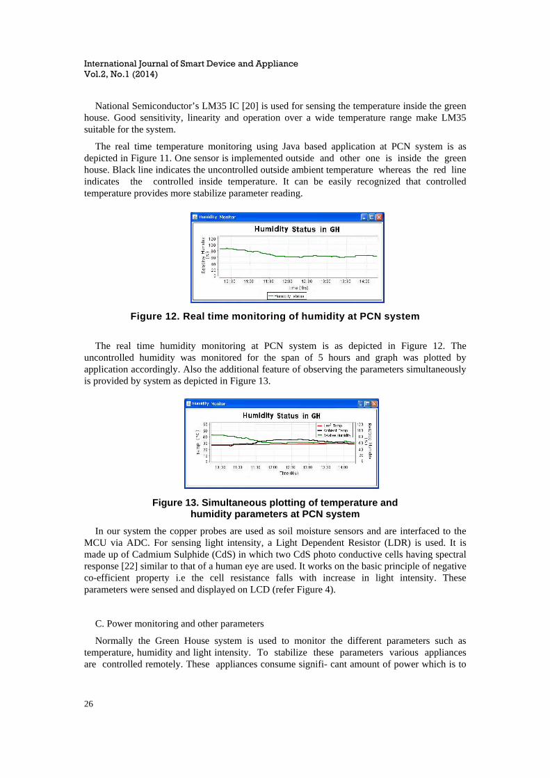
Figure 12. Real time monitoring of humidity at PCN system
The real time humidity monitoring at PCN system is as depicted in Figure 12. The uncontrolled humidity was monitored for the span of 5 hours and graph was plotted by application accordingly. Also the additional feature of observing the parameters simultaneously is provided by system as depicted in Figure 13.
Figure 13. Simultaneous plotting of temperature and humidity parameters at PCN system
In our system the copper probes are used as soil moisture sensors and are interfaced to the MCU via ADC. For sensing light intensity, a Light Dependent Resistor (LDR) is used. It is made up of Cadmium Sulphide (CdS) in which two CdS photo conductive cells having spectral response [22] similar to that of a human eye are used. It works on the basic principle of negative co-efficient property i.e the cell resistance falls with increase in light intensity. These parameters were sensed and displayed on LCD (refer Figure 4).
C. Power monitoring and other parameters
Normally the Green House system is used to monitor the different parameters such as temperature, humidity and light intensity. To stabilize these parameters various appliances are controlled remotely. These appliances consume signifi- cant amount of power which is to

International Journal of Smart Device and Appliance Vol.2, No.1 (2014)
27
be monitored for power conservation. Hence, the unique feature of real time power monitoring in green house is incorporated which is similar to system model in [23]. It enables the user to estimate the total power consumed by various loads as well as helps to recognize devices which maybe malfunctioning.
Figure 14. GUI developed for controlling the Loads
Figure 15. Real time power consumption monitoring at PCN system when all appliances are turned off
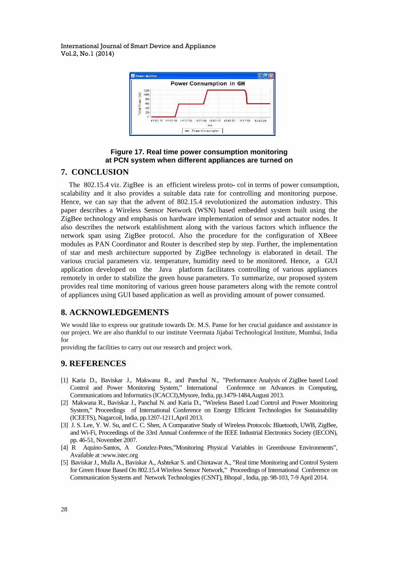
The system provides GUI for controlling the loads as shown in Figure 14. Power plots for real time power consumption monitoring are as depicted in further figures. When all the appliances in the Green House are turned off, the power plot is as depicted in Figure 15. Whereas Figure 16 depicts the power consumption when one appliance of rating 60 Watt is turned on. Further, Figure 17. depicts the total power consumed in the greenhouse by various appliances.
Figure 16. Real time power consumption monitoring at PCN system when one appliance (60 Watt rating) is turned on
International Journal of Smart Device and Appliance Vol.2, No.1 (2014)
28
Figure 17. Real time power consumption monitoring at PCN system when different appliances are turned on
7. CONCLUSION
The 802.15.4 viz. ZigBee is an efficient wireless proto- col in terms of power consumption, scalability and it also provides a suitable data rate for controlling and monitoring purpose. Hence, we can say that the advent of 802.15.4 revolutionized the automation industry. This paper describes a Wireless Sensor Network (WSN) based embedded system built using the ZigBee technology and emphasis on hardware implementation of sensor and actuator nodes. It also describes the network establishment along with the various factors which influence the network span using ZigBee protocol. Also the procedure for the configuration of XBeee modules as PAN Coordinator and Router is described step by step. Further, the implementation of star and mesh architecture supported by ZigBee technology is elaborated in detail. The various crucial parameters viz. temperature, humidity need to be monitored. Hence, a GUI application developed on the Java platform facilitates controlling of various appliances remotely in order to stabilize the green house parameters. To summarize, our proposed system provides real time monitoring of various green house parameters along with the remote control of appliances using GUI based application as well as providing amount of power consumed. 8. ACKNOWLEDGEMENTS
We would like to express our gratitude towards Dr. M.S. Panse for her crucial guidance and assistance in our project. We are also thankful to our institute Veermata Jijabai Technological Institute, Mumbai, India forproviding the facilities to carry out our research and project work. 9. REFERENCES [1] Karia D., Baviskar J., Makwana R., and Panchal N., ”Performance Analysis of ZigBee based Load
Control and Power Monitoring System,” International Conference on Advances in Computing, Communications and Informatics (ICACCI),Mysore, India, pp.1479-1484,August 2013.
[2] Makwana R., Baviskar J., Panchal N. and Karia D., ”Wireless Based Load Control and Power Monitoring System,” Proceedings of International Conference on Energy Efficient Technologies for Sustainability (ICEETS), Nagarcoil, India, pp.1207-1211,April 2013.
[3] J. S. Lee, Y. W. Su, and C. C. Shen, A Comparative Study of Wireless Protocols: Bluetooth, UWB, ZigBee, and Wi-Fi, Proceedings of the 33rd Annual Conference of the IEEE Industrial Electronics Society (IECON), pp. 46-51, November 2007.
[4] R Aquino-Santos, A Gonzlez-Potes,”Monitoring Physical Variables in Greenhouse Environments”, Available at :www.istec.org
[5] Baviskar J., Mulla A., Baviskar A., Ashtekar S. and Chintawar A., ”Real time Monitoring and Control System for Green House Based On 802.15.4 Wireless Sensor Network,” Proceedings of International Conference on Communication Systems and Network Technologies (CSNT), Bhopal , India, pp. 98-103, 7-9 April 2014.

International Journal of Smart Device and Appliance Vol.2, No.1 (2014)
29
[6] ZigBee Alliance, ZigBee Specification,ZigBee Alliance, ZigBee Docu- ment 053474r06, version 1.0, December 2004.
[7] J. S. Lee and Y. C. Huang, ITRI ZBnode: A ZigBee/IEEE 802.15.4 Plat- form for Wireless Sensor Networks, Proceedings of IEEE International Conference on Systems, Man, and Cybernetics, Taipei, Taiwan, vol. 2, pp. 1462-1467, October 2006
[8] ZigBee-Setting Standards for Energy-Efficient Control Networks, White Paper by Schneider Electric Industries SAS, no. P40110601EN, June 2011.
[9] E. Ferro and F. Potorti, Bluetooth and Wi-Fi wireless protocols: a survey and a comparison, Wireless Communications, IEEE, vol. 12, no. 1, pp. 12-26, February 2005.
[10] J. S. Lee, Performance Evaluation of IEEE 802.15.4 for Low-Rate Wireless Personal Area Networks, IEEE Transactions on Consumer Electronics, vol. 52, no. 3, pp. 742-749 , August 2006.
[11] V.K.Garg,”Wireless Communication and Networking”, ISBN: 978-81-312-1889-1,pp. 691-697. [12] M. Colotta, V.M.Salerno,” A Real Time Network Based On IEEE 802.15.4/ZigBee To Control Home
Automation Environment ”, Available at: http://guap.ru/guap/nids/pdf2010/collotta.pdf [13] XBee Series 2 OEM RF Modules Product Manual, Digi nternational, Inc., June 2007. [14] X-CTU Configuration and Test Utility Software User Guide, Digi International, Inc., August 2008. [15] Datasheet Available at:http://www.atmel.com/Images/doc8161.pdf [16] Datasheet Available at: http://yourduino.com/docs/Photoresistor-5516- datasheet.pdf [17] Z. Quan, Y. Xiang-long, Z. Yi-ming, W. Li-ren,”A wireless solution for greenhouse monitoring and control
system based on ZigBee tech- nology”,Journal of Zhejiang University 2007 , ISSN 1673-565X (Print); ISSN 1862-1775 (Online), pp.1584-1587
[18] Datasheet Available at: http://www.digi.com/pdf/xbeezbmodules.pdf [19] Zhou Yiming, Yang Xianglong,”A Design of Greenhouse Monitoring Control System Based on ZigBee
Wireless Sensor Network”,Proceedings of IEEE International Conference,2007. [20] Datasheet Available at: http://www.ti.com/lit/ds/symlink/lm35.pdf [21] Datasheet Available at: http://www.noodlehed.com/ebay/datasheets/hih4000.pdf [22] Datasheet Available at: http://www.sunrom.com [23] Baviskar, J.J., Mulla, A.Y., Baviskar, A.J., Panchal, N.B. and Makwana, R.P., ”Implementation of 802.15.4
for designing of home automation and power monitoring system,” Electrical, Electronics and Computer Science (SCEECS), 2014 IEEE Students’ Conference on, pp.1-5, 1-2 March 2014.