implementation and testing of a cam postprocessor for an industrial redundant workcell with...
TRANSCRIPT
Robotics and Computer-Integrated Manufacturing 28 (2012) 265–274
Contents lists available at SciVerse ScienceDirect
Robotics and Computer-Integrated Manufacturing
0736-58
doi:10.1
n Corr
E-m
luigraca
journal homepage: www.elsevier.com/locate/rcim
Implementation and testing of a CAM postprocessor for an industrialredundant workcell with evaluation of several fuzzified RedundancyResolution Schemes
Javier Andres a,n, Luis Gracia b, Josep Tornero b
a Department of Mechanical Engineering and Construction, Universitat Jaume I, Avda Vicent Sos Baynat s/n, 12071 Castellon, Spainb Instituto IDF, Universitat Polit�ecnica de Valencia, Camino de Vera s/n, 46022 Valencia, Spain
a r t i c l e i n f o
Article history:
Received 3 September 2010
Received in revised form
7 July 2011
Accepted 17 September 2011Available online 15 October 2011
Keywords:
Postprocessor
Redundant robot
Fuzzy
Milling
CAM
45/$ - see front matter & 2011 Elsevier Ltd. A
016/j.rcim.2011.09.008
esponding author. Tel.: þ34 964728143; fax:
ail addresses: [email protected] (J. Andres),
@isa.upv.es (L. Gracia), [email protected] (J
a b s t r a c t
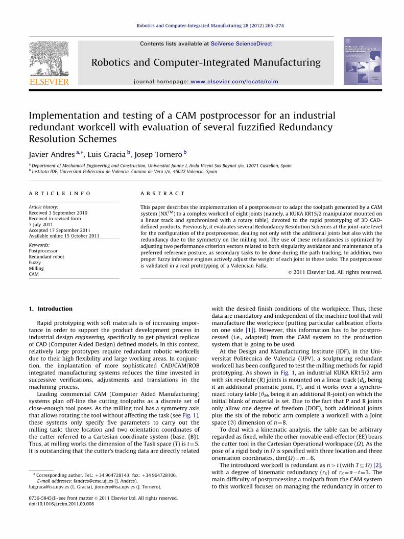
This paper describes the implementation of a postprocessor to adapt the toolpath generated by a CAM
system (NXTM) to a complex workcell of eight joints (namely, a KUKA KR15/2 manipulator mounted on
a linear track and synchronized with a rotary table), devoted to the rapid prototyping of 3D CAD-
defined products. Previously, it evaluates several Redundancy Resolution Schemes at the joint-rate level
for the configuration of the postprocessor, dealing not only with the additional joints but also with the
redundancy due to the symmetry on the milling tool. The use of these redundancies is optimized by
adjusting two performance criterion vectors related to both singularity avoidance and maintenance of a
preferred reference posture, as secondary tasks to be done during the path tracking. In addition, two
proper fuzzy inference engines actively adjust the weight of each joint in these tasks. The postprocessor
is validated in a real prototyping of a Valencian Falla.
& 2011 Elsevier Ltd. All rights reserved.
1. Introduction
Rapid prototyping with soft materials is of increasing impor-tance in order to support the product development process inindustrial design engineering, specifically to get physical replicasof CAD (Computer Aided Design) defined models. In this context,relatively large prototypes require redundant robotic workcellsdue to their high flexibility and large working areas. In conjunc-tion, the implantation of more sophisticated CAD/CAM/ROBintegrated manufacturing systems reduces the time invested insuccessive verifications, adjustments and translations in themachining process.
Leading commercial CAM (Computer Aided Manufacturing)systems plan off-line the cutting toolpaths as a discrete set ofclose-enough tool poses. As the milling tool has a symmetry axisthat allows rotating the tool without affecting the task (see Fig. 1),these systems only specify five parameters to carry out themilling task: three location and two orientation coordinates ofthe cutter referred to a Cartesian coordinate system (base, {B}).Thus, at milling works the dimension of the Task space (T) is t¼5.It is outstanding that the cutter’s tracking data are directly related
ll rights reserved.
þ34 964728106.
. Tornero).
with the desired finish conditions of the workpiece. Thus, thesedata are mandatory and independent of the machine tool that willmanufacture the workpiece (putting particular calibration effortson one side [1]). However, this information has to be postpro-cessed (i.e., adapted) from the CAM system to the productionsystem that is going to be used.
At the Design and Manufacturing Institute (IDF), in the Uni-versitat Polit�ecnica de Valencia (UPV), a sculpturing redundantworkcell has been configured to test the milling methods for rapidprototyping. As shown in Fig. 1, an industrial KUKA KR15/2 armwith six revolute (R) joints is mounted on a linear track (dL, beingit an additional prismatic joint, P), and it works over a synchro-nized rotary table (yM, being it an additional R-joint) on which theinitial blank of material is set. Due to the fact that P and R jointsonly allow one degree of freedom (DOF), both additional jointsplus the six of the robotic arm complete a workcell with a Jointspace (I) dimension of n¼8.
To deal with a kinematic analysis, the table can be arbitraryregarded as fixed, while the other movable end-effector (EE) bearsthe cutter tool in the Cartesian Operational workspace (O). As thepose of a rigid body in O is specified with three location and threeorientation coordinates, dim(O)¼m¼6.
The introduced workcell is redundant as n4t (with TDO) [2],with a degree of kinematic redundancy (rK) of rK¼n�t¼3. Themain difficulty of postprocessing a toolpath from the CAM systemto this workcell focuses on managing the redundancy in order to
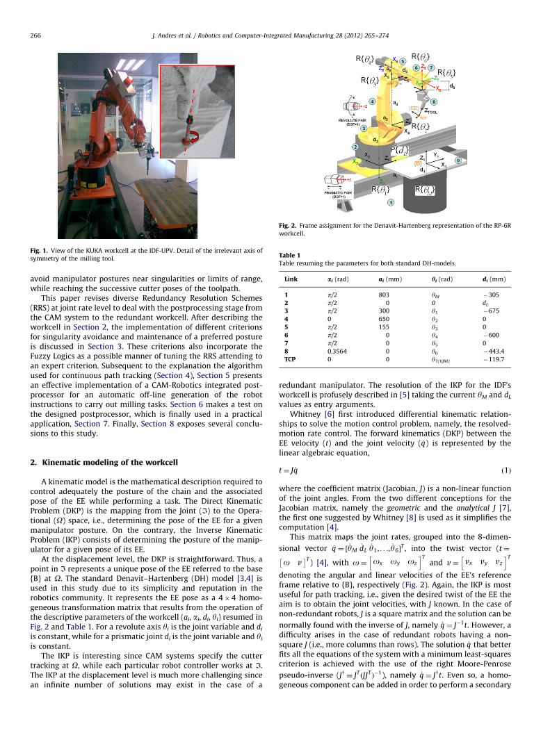
Fig. 1. View of the KUKA workcell at the IDF-UPV. Detail of the irrelevant axis of
symmetry of the milling tool.
Fig. 2. Frame assignment for the Denavit-Hartenberg representation of the RP-6R
workcell.
Table 1Table resuming the parameters for both standard DH-models.
Link ai (rad) ai (mm) hi (rad) di (mm)
1 p/2 803 yM �305
2 p/2 0 0 dL
3 p/2 300 y1 �675
4 0 650 y2 0
5 p/2 155 y3 0
6 p/2 0 y4 �600
7 p/2 0 y5 0
8 0.3564 0 y6 �443.4
TCP 0 0 y7(VJM) �119.7
J. Andres et al. / Robotics and Computer-Integrated Manufacturing 28 (2012) 265–274266
avoid manipulator postures near singularities or limits of range,while reaching the successive cutter poses of the toolpath.
This paper revises diverse Redundancy Resolution Schemes(RRS) at joint rate level to deal with the postprocessing stage fromthe CAM system to the redundant workcell. After describing theworkcell in Section 2, the implementation of different criterionsfor singularity avoidance and maintenance of a preferred postureis discussed in Section 3. These criterions also incorporate theFuzzy Logics as a possible manner of tuning the RRS attending toan expert criterion. Subsequent to the explanation the algorithmused for continuous path tracking (Section 4), Section 5 presentsan effective implementation of a CAM-Robotics integrated post-processor for an automatic off-line generation of the robotinstructions to carry out milling tasks. Section 6 makes a test onthe designed postprocessor, which is finally used in a practicalapplication, Section 7. Finally, Section 8 exposes several conclu-sions to this study.
2. Kinematic modeling of the workcell
A kinematic model is the mathematical description required tocontrol adequately the posture of the chain and the associatedpose of the EE while performing a task. The Direct KinematicProblem (DKP) is the mapping from the Joint (I) to the Opera-tional (O) space, i.e., determining the pose of the EE for a givenmanipulator posture. On the contrary, the Inverse KinematicProblem (IKP) consists of determining the posture of the manip-ulator for a given pose of its EE.
At the displacement level, the DKP is straightforward. Thus, apoint in I represents a unique pose of the EE referred to the base{B} at O. The standard Denavit–Hartenberg (DH) model [3,4] isused in this study due to its simplicity and reputation in therobotics community. It represents the EE pose as a 4�4 homo-geneous transformation matrix that results from the operation ofthe descriptive parameters of the workcell (ai, ai, di, yi) resumed inFig. 2 and Table 1. For a revolute axis yi is the joint variable and di
is constant, while for a prismatic joint di is the joint variable and yi
is constant.The IKP is interesting since CAM systems specify the cutter
tracking at O, while each particular robot controller works at I.The IKP at the displacement level is much more challenging sincean infinite number of solutions may exist in the case of a
redundant manipulator. The resolution of the IKP for the IDF’sworkcell is profusely described in [5] taking the current yM and dL
values as entry arguments.Whitney [6] first introduced differential kinematic relation-
ships to solve the motion control problem, namely, the resolved-motion rate control. The forward kinematics (DKP) between theEE velocity (t) and the joint velocity ( _q) is represented by thelinear algebraic equation,
t¼ J _q ð1Þ
where the coefficient matrix (Jacobian, J) is a non-linear functionof the joint angles. From the two different conceptions for theJacobian matrix, namely the geometric and the analytical J [7],the first one suggested by Whitney [8] is used as it simplifies thecomputation [4].
This matrix maps the joint rates, grouped into the 8-dimen-
sional vector _q ¼ ½ _yM_dL_y1,. . ., _y6�
T , into the twist vector (t¼
o v� �T
) [4], with o¼ ox oy oz
h iTand v¼ vx vy vz
h iT
denoting the angular and linear velocities of the EE’s referenceframe relative to {B}, respectively (Fig. 2). Again, the IKP is mostuseful for path tracking, i.e., given the desired twist of the EE theaim is to obtain the joint velocities, with J known. In the case ofnon-redundant robots, J is a square matrix and the solution can be
normally found with the inverse of J, namely _q ¼ J�1t. However, adifficulty arises in the case of redundant robots having a non-
square J (i.e., more columns than rows). The solution _q that betterfits all the equations of the system with a minimum least-squarescriterion is achieved with the use of the right Moore-Penrose
pseudo-inverse (Jy � JTðJJTÞ�1), namely _q ¼ Jyt. Even so, a homo-
geneous component can be added in order to perform a secondary
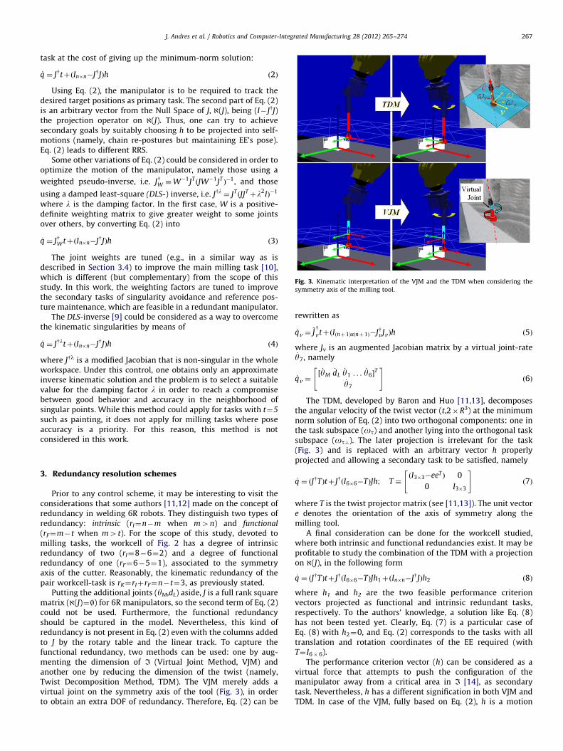
Fig. 3. Kinematic interpretation of the VJM and the TDM when considering the
symmetry axis of the milling tool.
J. Andres et al. / Robotics and Computer-Integrated Manufacturing 28 (2012) 265–274 267
task at the cost of giving up the minimum-norm solution:
_q ¼ JytþðIn�n�JyJÞh ð2Þ
Using Eq. (2), the manipulator is to be required to track thedesired target positions as primary task. The second part of Eq. (2)is an arbitrary vector from the Null Space of J, @(J), being (I� JyJ)the projection operator on @(J). Thus, one can try to achievesecondary goals by suitably choosing h to be projected into self-motions (namely, chain re-postures but maintaining EE’s pose).Eq. (2) leads to different RRS.
Some other variations of Eq. (2) could be considered in order tooptimize the motion of the manipulator, namely those using a
weighted pseudo-inverse, i.e. JyW �W�1JTðJW�1JT
Þ�1, and those
using a damped least-square (DLS-) inverse, i.e. Jyl ¼ JTðJJTþl2IÞ�1
where l is the damping factor. In the first case, W is a positive-definite weighting matrix to give greater weight to some jointsover others, by converting Eq. (2) into
_q ¼ JyW tþðIn�n�JyJÞh ð3Þ
The joint weights are tuned (e.g., in a similar way as isdescribed in Section 3.4) to improve the main milling task [10],which is different (but complementary) from the scope of thisstudy. In this work, the weighting factors are tuned to improvethe secondary tasks of singularity avoidance and reference pos-ture maintenance, which are feasible in a redundant manipulator.
The DLS-inverse [9] could be considered as a way to overcomethe kinematic singularities by means of
_q ¼ JyltþðIn�n�JyJÞh ð4Þ
where Jyl is a modified Jacobian that is non-singular in the wholeworkspace. Under this control, one obtains only an approximateinverse kinematic solution and the problem is to select a suitablevalue for the damping factor l in order to reach a compromisebetween good behavior and accuracy in the neighborhood ofsingular points. While this method could apply for tasks with t¼5
such as painting, it does not apply for milling tasks where poseaccuracy is a priority. For this reason, this method is notconsidered in this work.
3. Redundancy resolution schemes
Prior to any control scheme, it may be interesting to visit theconsiderations that some authors [11,12] made on the concept ofredundancy in welding 6R robots. They distinguish two types ofredundancy: intrinsic (rI¼n�m when m4n) and functional
(rF¼m�t when m4t). For the scope of this study, devoted tomilling tasks, the workcell of Fig. 2 has a degree of intrinsicredundancy of two (rI¼8�6¼2) and a degree of functionalredundancy of one (rF¼6�5¼1), associated to the symmetryaxis of the cutter. Reasonably, the kinematic redundancy of thepair workcell-task is rK¼rIþrF¼n�t¼3, as previously stated.
Putting the additional joints (yM,dL) aside, J is a full rank squarematrix (@(J)¼|) for 6R manipulators, so the second term of Eq. (2)could not be used. Furthermore, the functional redundancyshould be captured in the model. Nevertheless, this kind ofredundancy is not present in Eq. (2) even with the columns addedto J by the rotary table and the linear track. To capture thefunctional redundancy, two methods can be used: one by aug-menting the dimension of I (Virtual Joint Method, VJM) andanother one by reducing the dimension of the twist (namely,Twist Decomposition Method, TDM). The VJM merely adds avirtual joint on the symmetry axis of the tool (Fig. 3), in orderto obtain an extra DOF of redundancy. Therefore, Eq. (2) can be
rewritten as
_qv ¼~Jy
vtþðIðnþ1Þxðnþ1Þ�JyvJvÞh ð5Þ
where Jv is an augmented Jacobian matrix by a virtual joint-rate_y7, namely
_qv ¼½ _yM
_dL_y1 . . . _y6�
T
_y7
" #ð6Þ
The TDM, developed by Baron and Huo [11,13], decomposesthe angular velocity of the twist vector (t,2�R3) at the minimumnorm solution of Eq. (2) into two orthogonal components: one inthe task subspace (ot) and another lying into the orthogonal tasksubspace (ot?). The later projection is irrelevant for the task(Fig. 3) and is replaced with an arbitrary vector h properlyprojected and allowing a secondary task to be satisfied, namely
_q ¼ ðJyTÞtþ JyðI6�6�TÞJh; T �ðI3�3�eeT Þ 0
0 I3�3
" #ð7Þ
where T is the twist projector matrix (see [11,13]). The unit vectore denotes the orientation of the axis of symmetry along themilling tool.
A final consideration can be done for the workcell studied,where both intrinsic and functional redundancies exist. It may beprofitable to study the combination of the TDM with a projectionon @(J), in the following form
_q ¼ ðJyTÞtþ JyðI6�6�TÞJh1þðIn�n�JyJÞh2 ð8Þ
where h1 and h2 are the two feasible performance criterionvectors projected as functional and intrinsic redundant tasks,respectively. To the authors’ knowledge, a solution like Eq. (8)has not been tested yet. Clearly, Eq. (7) is a particular case ofEq. (8) with h2¼0, and Eq. (2) corresponds to the tasks with alltranslation and rotation coordinates of the EE required (withT¼ I6�6).
The performance criterion vector (h) can be considered as avirtual force that attempts to push the configuration of themanipulator away from a critical area in I [14], as secondarytask. Nevertheless, h has a different signification in both VJM andTDM. In case of the VJM, fully based on Eq. (2), h is a motion
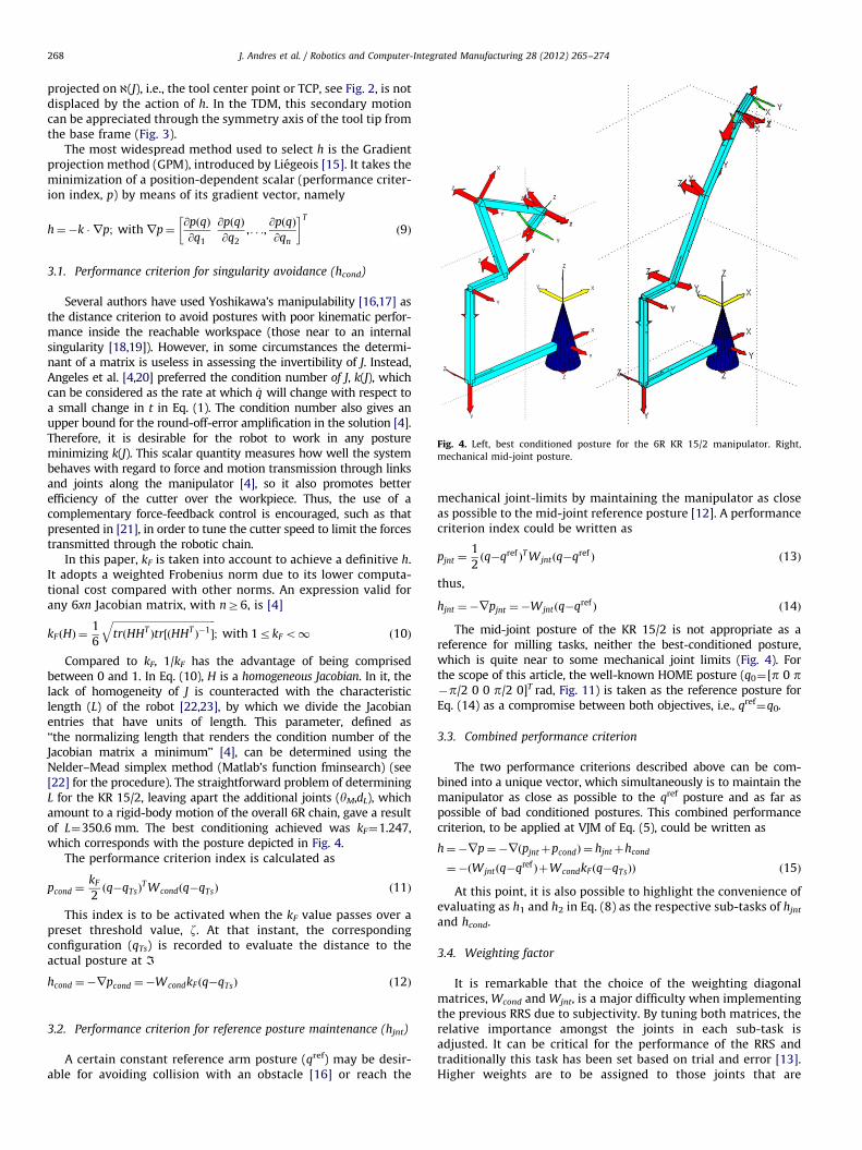
Fig. 4. Left, best conditioned posture for the 6R KR 15/2 manipulator. Right,
mechanical mid-joint posture.
J. Andres et al. / Robotics and Computer-Integrated Manufacturing 28 (2012) 265–274268
projected on @(J), i.e., the tool center point or TCP, see Fig. 2, is notdisplaced by the action of h. In the TDM, this secondary motioncan be appreciated through the symmetry axis of the tool tip fromthe base frame (Fig. 3).
The most widespread method used to select h is the Gradientprojection method (GPM), introduced by Liegeois [15]. It takes theminimization of a position-dependent scalar (performance criter-ion index, p) by means of its gradient vector, namely
h¼�k � rp; withrp¼@pðqÞ
@q1
@pðqÞ
@q2
,. . .,@pðqÞ
@qn
� �T
ð9Þ
3.1. Performance criterion for singularity avoidance (hcond)
Several authors have used Yoshikawa’s manipulability [16,17] asthe distance criterion to avoid postures with poor kinematic perfor-mance inside the reachable workspace (those near to an internalsingularity [18,19]). However, in some circumstances the determi-nant of a matrix is useless in assessing the invertibility of J. Instead,Angeles et al. [4,20] preferred the condition number of J, k(J), whichcan be considered as the rate at which _q will change with respect toa small change in t in Eq. (1). The condition number also gives anupper bound for the round-off-error amplification in the solution [4].Therefore, it is desirable for the robot to work in any postureminimizing k(J). This scalar quantity measures how well the systembehaves with regard to force and motion transmission through linksand joints along the manipulator [4], so it also promotes betterefficiency of the cutter over the workpiece. Thus, the use of acomplementary force-feedback control is encouraged, such as thatpresented in [21], in order to tune the cutter speed to limit the forcestransmitted through the robotic chain.
In this paper, kF is taken into account to achieve a definitive h.It adopts a weighted Frobenius norm due to its lower computa-tional cost compared with other norms. An expression valid forany 6xn Jacobian matrix, with nZ6, is [4]
kF ðHÞ ¼1
6
ffiffiffiffiffiffiffiffiffiffiffiffiffiffiffiffiffiffiffiffiffiffiffiffiffiffiffiffiffiffiffiffiffiffiffiffiffiffiffiffiffitrðHHT
Þtr½ðHHTÞ�1�
q; with 1rkF o1 ð10Þ
Compared to kF, 1/kF has the advantage of being comprisedbetween 0 and 1. In Eq. (10), H is a homogeneous Jacobian. In it, thelack of homogeneity of J is counteracted with the characteristiclength (L) of the robot [22,23], by which we divide the Jacobianentries that have units of length. This parameter, defined as‘‘the normalizing length that renders the condition number of theJacobian matrix a minimum’’ [4], can be determined using theNelder–Mead simplex method (Matlab’s function fminsearch) (see[22] for the procedure). The straightforward problem of determiningL for the KR 15/2, leaving apart the additional joints (yM,dL), whichamount to a rigid-body motion of the overall 6R chain, gave a resultof L¼350.6 mm. The best conditioning achieved was kF¼1.247,which corresponds with the posture depicted in Fig. 4.
The performance criterion index is calculated as
pcond ¼kF
2ðq�qTsÞ
T Wcondðq�qTsÞ ð11Þ
This index is to be activated when the kF value passes over apreset threshold value, z. At that instant, the correspondingconfiguration (qTs) is recorded to evaluate the distance to theactual posture at I
hcond ¼�rpcond ¼�WcondkF ðq�qTsÞ ð12Þ
3.2. Performance criterion for reference posture maintenance (hjnt)
A certain constant reference arm posture (qref) may be desir-able for avoiding collision with an obstacle [16] or reach the
mechanical joint-limits by maintaining the manipulator as closeas possible to the mid-joint reference posture [12]. A performancecriterion index could be written as
pjnt ¼1
2ðq�qref Þ
T Wjntðq�qref Þ ð13Þ
thus,
hjnt ¼�rpjnt ¼�Wjntðq�qref Þ ð14Þ
The mid-joint posture of the KR 15/2 is not appropriate as areference for milling tasks, neither the best-conditioned posture,which is quite near to some mechanical joint limits (Fig. 4). Forthe scope of this article, the well-known HOME posture (q0¼[p 0 p�p/2 0 0 p/2 0]T rad, Fig. 11) is taken as the reference posture forEq. (14) as a compromise between both objectives, i.e., qref
¼q0.
3.3. Combined performance criterion
The two performance criterions described above can be com-bined into a unique vector, which simultaneously is to maintain themanipulator as close as possible to the qref posture and as far aspossible of bad conditioned postures. This combined performancecriterion, to be applied at VJM of Eq. (5), could be written as
h¼�rp¼�rðpjntþpcondÞ ¼ hjntþhcond
¼�ðWjntðq�qref ÞþWcondkF ðq�qTsÞÞ ð15Þ
At this point, it is also possible to highlight the convenience ofevaluating as h1 and h2 in Eq. (8) as the respective sub-tasks of hjnt
and hcond.
3.4. Weighting factor
It is remarkable that the choice of the weighting diagonalmatrices, Wcond and Wjnt, is a major difficulty when implementingthe previous RRS due to subjectivity. By tuning both matrices, therelative importance amongst the joints in each sub-task isadjusted. It can be critical for the performance of the RRS andtraditionally this task has been set based on trial and error [13].Higher weights are to be assigned to those joints that are
J. Andres et al. / Robotics and Computer-Integrated Manufacturing 28 (2012) 265–274 269
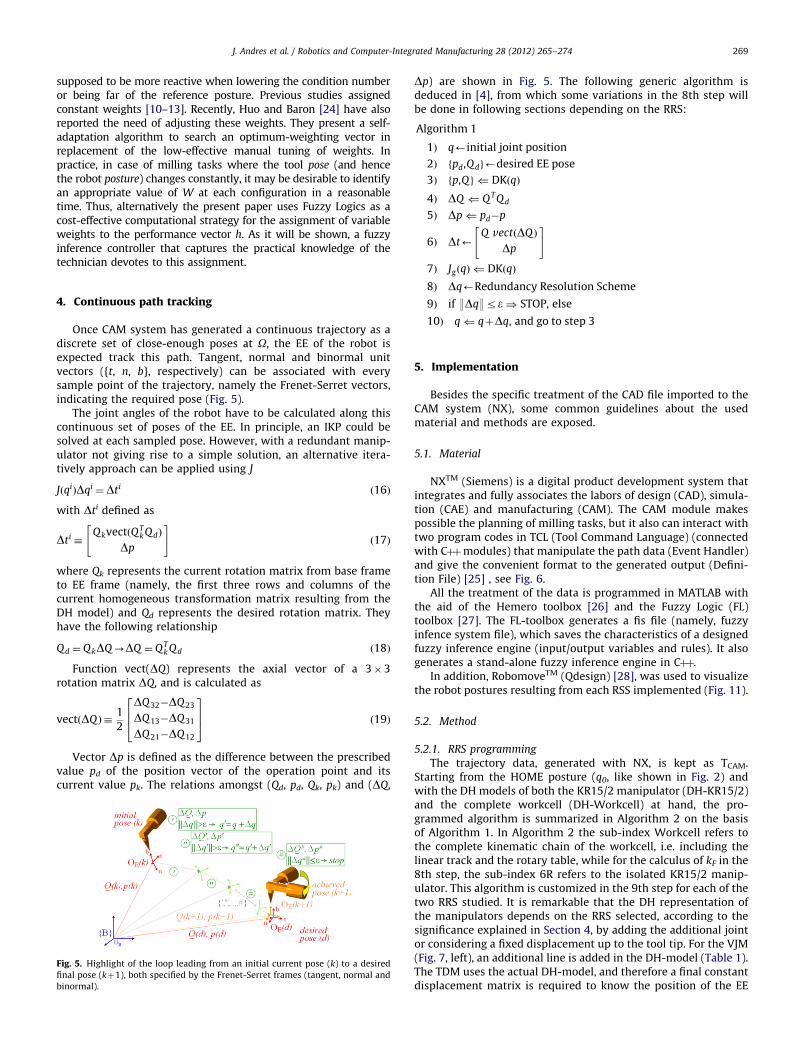
supposed to be more reactive when lowering the condition numberor being far of the reference posture. Previous studies assignedconstant weights [10–13]. Recently, Huo and Baron [24] have alsoreported the need of adjusting these weights. They present a self-adaptation algorithm to search an optimum-weighting vector inreplacement of the low-effective manual tuning of weights. Inpractice, in case of milling tasks where the tool pose (and hencethe robot posture) changes constantly, it may be desirable to identifyan appropriate value of W at each configuration in a reasonabletime. Thus, alternatively the present paper uses Fuzzy Logics as acost-effective computational strategy for the assignment of variableweights to the performance vector h. As it will be shown, a fuzzyinference controller that captures the practical knowledge of thetechnician devotes to this assignment.
4. Continuous path tracking
Once CAM system has generated a continuous trajectory as adiscrete set of close-enough poses at O, the EE of the robot isexpected track this path. Tangent, normal and binormal unitvectors ({t, n, b}, respectively) can be associated with everysample point of the trajectory, namely the Frenet-Serret vectors,indicating the required pose (Fig. 5).
The joint angles of the robot have to be calculated along thiscontinuous set of poses of the EE. In principle, an IKP could besolved at each sampled pose. However, with a redundant manip-ulator not giving rise to a simple solution, an alternative itera-tively approach can be applied using J
JðqiÞDqi ¼Dti ð16Þ
with Dti defined as
Dti �QkvectðQT
k QdÞ
Dp
" #ð17Þ
where Qk represents the current rotation matrix from base frameto EE frame (namely, the first three rows and columns of thecurrent homogeneous transformation matrix resulting from theDH model) and Qd represents the desired rotation matrix. Theyhave the following relationship
Qd ¼ QkDQ-DQ ¼ QTk Qd ð18Þ
Function vect(DQ) represents the axial vector of a 3�3rotation matrix DQ, and is calculated as
vectðDQ Þ �1
2
DQ32�DQ23
DQ13�DQ31
DQ21�DQ12
264
375 ð19Þ
Vector Dp is defined as the difference between the prescribedvalue pd of the position vector of the operation point and itscurrent value pk. The relations amongst (Qd, pd, Qk, pk) and (DQ,
Fig. 5. Highlight of the loop leading from an initial current pose (k) to a desired
final pose (kþ1), both specified by the Frenet-Serret frames (tangent, normal and
binormal).
Dp) are shown in Fig. 5. The following generic algorithm isdeduced in [4], from which some variations in the 8th step willbe done in following sections depending on the RRS:
Algorithm 1
1Þ q’initial joint position
2Þ fpd,Qdg’desired EE pose
3Þ fp,Qg ( DKðqÞ
4Þ DQ ( QT Qd
5Þ Dp( pd�p
6Þ Dt’Q vectðDQ Þ
Dp
" #
7Þ JgðqÞ ( DKðqÞ
8Þ Dq’Redundancy Resolution Scheme
9Þ if :Dq:re) STOP, else
10Þ q( qþDq, and go to step 3
5. Implementation
Besides the specific treatment of the CAD file imported to theCAM system (NX), some common guidelines about the usedmaterial and methods are exposed.
5.1. Material
NXTM (Siemens) is a digital product development system thatintegrates and fully associates the labors of design (CAD), simula-tion (CAE) and manufacturing (CAM). The CAM module makespossible the planning of milling tasks, but it also can interact withtwo program codes in TCL (Tool Command Language) (connectedwith Cþþmodules) that manipulate the path data (Event Handler)and give the convenient format to the generated output (Defini-tion File) [25] , see Fig. 6.
All the treatment of the data is programmed in MATLAB withthe aid of the Hemero toolbox [26] and the Fuzzy Logic (FL)toolbox [27]. The FL-toolbox generates a fis file (namely, fuzzyinfence system file), which saves the characteristics of a designedfuzzy inference engine (input/output variables and rules). It alsogenerates a stand-alone fuzzy inference engine in Cþþ.
In addition, RobomoveTM (Qdesign) [28], was used to visualizethe robot postures resulting from each RSS implemented (Fig. 11).
5.2. Method
5.2.1. RRS programming
The trajectory data, generated with NX, is kept as TCAM.Starting from the HOME posture (q0, like shown in Fig. 2) andwith the DH models of both the KR15/2 manipulator (DH-KR15/2)and the complete workcell (DH-Workcell) at hand, the pro-grammed algorithm is summarized in Algorithm 2 on the basisof Algorithm 1. In Algorithm 2 the sub-index Workcell refers tothe complete kinematic chain of the workcell, i.e. including thelinear track and the rotary table, while for the calculus of kF in the8th step, the sub-index 6R refers to the isolated KR15/2 manip-ulator. This algorithm is customized in the 9th step for each of thetwo RRS studied. It is remarkable that the DH representation ofthe manipulators depends on the RRS selected, according to thesignificance explained in Section 4, by adding the additional jointor considering a fixed displacement up to the tool tip. For the VJM(Fig. 7, left), an additional line is added in the DH-model (Table 1).The TDM uses the actual DH-model, and therefore a final constantdisplacement matrix is required to know the position of the EE
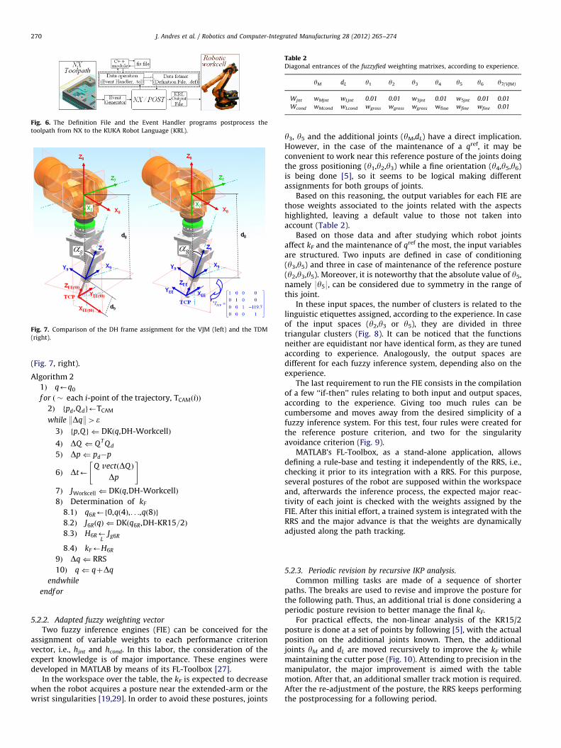
Fig. 6. The Definition File and the Event Handler programs postprocess the
toolpath from NX to the KUKA Robot Language (KRL).
Fig. 7. Comparison of the DH frame assignment for the VJM (left) and the TDM
(right).
Table 2Diagonal entrances of the fuzzyfied weighting matrixes, according to experience.
yM dL y1 y2 y3 y4 y5 y6 y7(VJM)
Wjnt wMjnt wLjnt 0.01 0.01 w3jnt 0.01 w5jnt 0.01 0.01
Wcond wMcond wLcond wgross wgross wgross wfine wfine wfine 0.01
J. Andres et al. / Robotics and Computer-Integrated Manufacturing 28 (2012) 265–274270
(Fig. 7, right).
Algorithm 2
1Þ q’q0
f or ð � each i-point of the trajectory, TCAMðiÞÞ
2Þ fpd,Qdg’TCAM
while :Dq:4e3Þ fp,Qg ( DKðq,DH-WorkcellÞ
4Þ DQ ( QT Qd
5Þ Dp( pd�p
6Þ Dt’Q vectðDQ Þ
Dp
" #
7Þ JWorkcell ( DKðq,DH-WorkcellÞ
8Þ Determination of kF
8:1Þ q6R’f0,qð4Þ,. . .,qð8Þg
8:2Þ J6RðqÞ ( DKðq6R,DH-KR15=2Þ
8:3Þ H6R’L
Jg6R
8:4Þ kF’H6R
9Þ Dq( RRS
10Þ q( qþDq
endwhile
endf or
5.2.2. Adapted fuzzy weighting vector
Two fuzzy inference engines (FIE) can be conceived for theassignment of variable weights to each performance criterionvector, i.e., hjnt and hcond. In this labor, the consideration of theexpert knowledge is of major importance. These engines weredeveloped in MATLAB by means of its FL-Toolbox [27].
In the workspace over the table, the kF is expected to decreasewhen the robot acquires a posture near the extended-arm or thewrist singularities [19,29]. In order to avoid these postures, joints
y3, y5 and the additional joints (yM,dL) have a direct implication.However, in the case of the maintenance of a qref, it may beconvenient to work near this reference posture of the joints doingthe gross positioning (y1,y2,y3) while a fine orientation (y4,y5,y6)is being done [5], so it seems to be logical making differentassignments for both groups of joints.
Based on this reasoning, the output variables for each FIE arethose weights associated to the joints related with the aspectshighlighted, leaving a default value to those not taken intoaccount (Table 2).
Based on those data and after studying which robot jointsaffect kF and the maintenance of qref the most, the input variablesare structured. Two inputs are defined in case of conditioning(y3,y5) and three in case of maintenance of the reference posture(y2,y3,y5). Moreover, it is noteworthy that the absolute value of y5,namely 9y59, can be considered due to symmetry in the range ofthis joint.
In these input spaces, the number of clusters is related to thelinguistic etiquettes assigned, according to the experience. In caseof the input spaces (y2,y3 or y5), they are divided in threetriangular clusters (Fig. 8). It can be noticed that the functionsneither are equidistant nor have identical form, as they are tunedaccording to experience. Analogously, the output spaces aredifferent for each fuzzy inference system, depending also on theexperience.
The last requirement to run the FIE consists in the compilationof a few ‘‘if-then’’ rules relating to both input and output spaces,according to the experience. Giving too much rules can becumbersome and moves away from the desired simplicity of afuzzy inference system. For this test, four rules were created forthe reference posture criterion, and two for the singularityavoidance criterion (Fig. 9).
MATLAB’s FL-Toolbox, as a stand-alone application, allowsdefining a rule-base and testing it independently of the RRS, i.e.,checking it prior to its integration with a RRS. For this purpose,several postures of the robot are supposed within the workspaceand, afterwards the inference process, the expected major reac-tivity of each joint is checked with the weights assigned by theFIE. After this initial effort, a trained system is integrated with theRRS and the major advance is that the weights are dynamicallyadjusted along the path tracking.
5.2.3. Periodic revision by recursive IKP analysis.
Common milling tasks are made of a sequence of shorterpaths. The breaks are used to revise and improve the posture forthe following path. Thus, an additional trial is done considering aperiodic posture revision to better manage the final kF.
For practical effects, the non-linear analysis of the KR15/2posture is done at a set of points by following [5], with the actualposition on the additional joints known. Then, the additionaljoints yM and dL are moved recursively to improve the kF whilemaintaining the cutter pose (Fig. 10). Attending to precision in themanipulator, the major improvement is aimed with the tablemotion. After that, an additional smaller track motion is required.After the re-adjustment of the posture, the RRS keeps performingthe postprocessing for a following period.
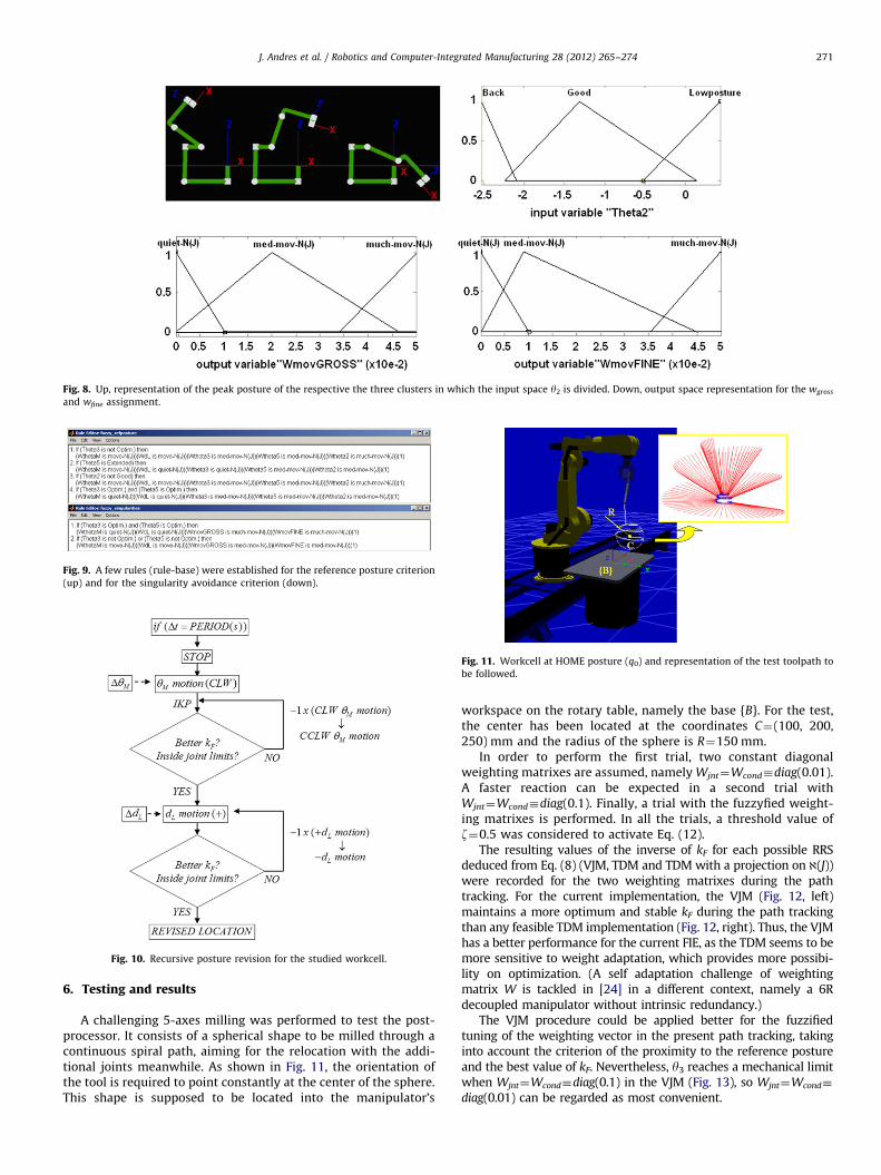
Fig. 8. Up, representation of the peak posture of the respective the three clusters in which the input space y2 is divided. Down, output space representation for the wgross
and wfine assignment.
Fig. 9. A few rules (rule-base) were established for the reference posture criterion
(up) and for the singularity avoidance criterion (down).
Fig. 10. Recursive posture revision for the studied workcell.
Fig. 11. Workcell at HOME posture (q0) and representation of the test toolpath to
be followed.
J. Andres et al. / Robotics and Computer-Integrated Manufacturing 28 (2012) 265–274 271
6. Testing and results
A challenging 5-axes milling was performed to test the post-processor. It consists of a spherical shape to be milled through acontinuous spiral path, aiming for the relocation with the addi-tional joints meanwhile. As shown in Fig. 11, the orientation ofthe tool is required to point constantly at the center of the sphere.This shape is supposed to be located into the manipulator’s
workspace on the rotary table, namely the base {B}. For the test,the center has been located at the coordinates C¼(100, 200,250) mm and the radius of the sphere is R¼150 mm.
In order to perform the first trial, two constant diagonalweighting matrixes are assumed, namely Wjnt¼Wcond�diag(0.01).A faster reaction can be expected in a second trial withWjnt¼Wcond�diag(0.1). Finally, a trial with the fuzzyfied weight-ing matrixes is performed. In all the trials, a threshold value ofz¼0.5 was considered to activate Eq. (12).
The resulting values of the inverse of kF for each possible RRSdeduced from Eq. (8) (VJM, TDM and TDM with a projection on @(J))were recorded for the two weighting matrixes during the pathtracking. For the current implementation, the VJM (Fig. 12, left)maintains a more optimum and stable kF during the path trackingthan any feasible TDM implementation (Fig. 12, right). Thus, the VJMhas a better performance for the current FIE, as the TDM seems to bemore sensitive to weight adaptation, which provides more possibi-lity on optimization. (A self adaptation challenge of weightingmatrix W is tackled in [24] in a different context, namely a 6Rdecoupled manipulator without intrinsic redundancy.)
The VJM procedure could be applied better for the fuzzifiedtuning of the weighting vector in the present path tracking, takinginto account the criterion of the proximity to the reference postureand the best value of kF. Nevertheless, y3 reaches a mechanical limitwhen Wjnt¼Wcond�diag(0.1) in the VJM (Fig. 13), so Wjnt¼Wcond�
diag(0.01) can be regarded as most convenient.
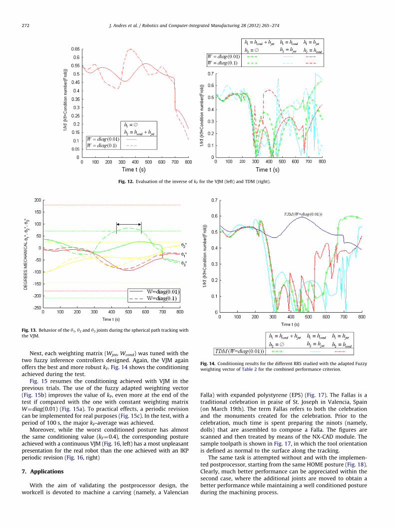
Fig. 12. Evaluation of the inverse of kF for the VJM (left) and TDM (right).
Fig. 13. Behavior of the y1, y2 and y3 joints during the spherical path tracking with
the VJM.
Fig. 14. Conditioning results for the different RRS studied with the adapted Fuzzy
weighting vector of Table 2 for the combined performance criterion.
J. Andres et al. / Robotics and Computer-Integrated Manufacturing 28 (2012) 265–274272
Next, each weighting matrix (Wjnt, Wcond) was tuned with thetwo fuzzy inference controllers designed. Again, the VJM againoffers the best and more robust kF. Fig. 14 shows the conditioningachieved during the test.
Fig. 15 resumes the conditioning achieved with VJM in theprevious trials. The use of the fuzzy adapted weighting vector(Fig. 15b) improves the value of kF, even more at the end of thetest if compared with the one with constant weighting matrixW¼diag(0.01) (Fig. 15a). To practical effects, a periodic revisioncan be implemented for real purposes (Fig. 15c). In the test, with aperiod of 100 s, the major kF-average was achieved.
Moreover, while the worst conditioned posture has almostthe same conditioning value (kF¼0.4), the corresponding postureachieved with a continuous VJM (Fig. 16, left) has a most unpleasantpresentation for the real robot than the one achieved with an IKPperiodic revision (Fig. 16, right)
7. Applications
With the aim of validating the postprocessor design, theworkcell is devoted to machine a carving (namely, a Valencian
Falla) with expanded polystyrene (EPS) (Fig. 17). The Fallas is atraditional celebration in praise of St. Joseph in Valencia, Spain(on March 19th). The term Fallas refers to both the celebrationand the monuments created for the celebration. Prior to thecelebration, much time is spent preparing the ninots (namely,dolls) that are assembled to compose a Falla. The figures arescanned and then treated by means of the NX-CAD module. Thesample toolpath is shown in Fig. 17, in which the tool orientationis defined as normal to the surface along the tracking.
The same task is attempted without and with the implemen-ted postprocessor, starting from the same HOME posture (Fig. 18).Clearly, much better performance can be appreciated within thesecond case, where the additional joints are moved to obtain abetter performance while maintaining a well conditioned postureduring the machining process.

Fig. 15. Comparison of the conditioning achieved with the different VJM trials:
(a) with constant weighting vector; (b) with fuzzy adapted weighting vector;
(c) with fuzzy adapted weighting vector and a periodic IKP revision.
Fig. 16. Worst conditioned postures for the continuous VJM (left) and the VJM
with an IKP periodic revision (right).
Fig. 17. A 5-axes toolpath is planned on the ninot to test the postprocessor.
Fig. 18. The white toolpath, representing the area being reachable during the
machining process, is enhanced with the programmed algorithm (left), if com-
pared with a fixed table and track (right).
J. Andres et al. / Robotics and Computer-Integrated Manufacturing 28 (2012) 265–274 273
All joints are maintained between the allowable limits, while1/kF is kept between reasonable values, as shown in Fig. 19.
Fig. 19. Conditioning of the manipulator while the milling of the Falla.
8. Conclusions
The present paper has been focused on the postprocessing ofthe information generated by the NX-CAM system towards theKUKA controller of a complex workcell devoted to milling tasks.As the main contribution, after studying the capabilities of the set,a functional postprocessor is programmed inside the CAM system.
Different RRS on the joint-rate level have been tested and the bestperformance for the current CAM application have been achievedwith the VJM. This RRS deals with the functional redundancy (theone due to the symmetry axis of the cutter) by considering anadditional (virtual) joint in the referred symmetry axis.
In the design of the secondary tasks, namely self-motions to avoidbad conditioned postures on the reachable workspace, the conditionnumber of the Homogeneous Jacobian has given better results thanthe other performance indices. In fact, the better the posture isconditioned, the better the manipulator behaves regarding to motion
and force transmission through the robotic chain. In this sense, it isadvisable to implement a complementary force-feedback control totune the cutter speed to limit the forces transmitted through therobotic chain. This issue remains as further work.
J. Andres et al. / Robotics and Computer-Integrated Manufacturing 28 (2012) 265–274274
Also the expert fuzzy systems have demonstrated to be analternative to actively manage some parameters related withexperience, opposed to those previously fixed, even in thosesystems where it is difficult (or even impossible) to find amathematical model of the process to control. In this study, afuzzy inference engine improved the adjustment of the weights ofthe performance vectors for every robot situation, boosting theperformance of the RRS and thus, of the postprocessor module. Itis also worth mentioning the great influence on the result of theperformance vector h.
The implemented postprocessor has been effectively tested witha graphical simulation of a demanding machining. Finally, it also hasbeen successfully validated in a real prototyping of a Valencian Falla,done in EPS by means of 5-axes milling operations.
With the same guidelines, this postprocessor is expected to beeasily applicable not only on any industrial robot, but also fordifferent applications such as welding or painting labors.
Acknowledgments
This research is partially supported by the Technical Universityof Valencia (PAID-00–09), project PROMETEO 2009/063 of Gen-eralitat Valenciana and research project DPI2009-14744-C03-01of the Spanish Government.
References
[1] Andres J, Gracia L, Tornero J. Calibration and control of a redundant roboticworkcell for milling tasks. International Journal of Computer IntegratedManufacturing 2011;24(6):561–73.
[2] Patel RV, Shadpey F. Control of redundant robot manipulators: theory andexperiments. Springer; 2005.
[3] Hartenberg RS, Denavit J. A kinematic notation for lower pair mechanismsbased on matrices. Journal of Applied Mechanics 1955;77:215–21.
[4] Angeles J. Fundamentals of robotic mechanical systems: theory, methods andalgorithms. New York: Springer; 2003.
[5] J Andres, L Gracia, J Tornero. Inverse kinematics of a redundant manipulatorfor CAM integration. An industrial perspective of implementation. In:Proceedings of the 2009 IEEE international conference on mechatronics,Malaga; 2009.
[6] Whitney DE. Resolved motion rate control of manipulators and humanprostheses. IEEE Transactions on Man–Machine Systems 1969;10(2):47–53.
[7] Sciavicco L, Siciliano B. Modelling and control of robot manipulators. London:Springer; 2000 [pp. 79–87].
[8] Whitney DE. The mathematics of coordinated control of prosthetic arms andmanipulator. ASME Journal of Dynamics Systems, Measurement and Control1972;94(4):303–9.
[9] Chiaverini S, Oriolo G, Walker ID, Siciliano B, Khatib O. Kinematicallyredundant manipulators; Springer Handbook of Robotics. Springer-Verlag;2008 [pp. 253].
[10] Honegger M, Codourey A. Redundancy resolution of a cartesian spaceoperated heavy industrial manipulator. IEEE International Conference onRobotics and Automation 1998;3:2094–8.
[11] Huo L, Baron L. Kinematic inversion of functionally-redundant serial manip-ulators: application to arc-welding. Transactions of the Canadian Society forMechanical Engineering 2005. [Canada].
[12] L. Baron. A joint-limits avoidance strategy for arc-welding robots. In:Proceedings of the international conference on integrated design andmanufacturing in mechanical engineering, Montreal, Canada; May 2000.
[13] Huo L, Baron L. The joint-limits and singularity avoidance in robotic welding.Industrial Robot; An International Journal 2008;35(5):456–64.
[14] Kemeny Z. Mapping, detection and handling of singularities for kinematicallyredundant serial manipulators. Periodica Polytechnica Ser El Eng2002;46(1):29–45.
[15] Liegeois A. Automatic supervisory control of the configuration and behaviorof multibody mechanisms. IEEE Transactions on Systems, Man, and Cyber-netics 1977;SMC-7:245–50.
[16] Yoshikawa T. Analysis and control of robot manipulators with redundancy.Robotics Research: The First International Symposium 1984:735–47.
[17] Yoshikawa T. Manipulability of Robotic Mechanisms. International Journal ofRobotics Research 1985;4(2):3–9.
[18] Gracia L, Andres J, Tornero J. Trajectory tracking with a 6R serial industrialrobot with ordinary and non-ordinary singularities. International Journal ofControl, Automation and Systems 2009;7(1):85–96.
[19] Hayes MDJ, Husty ML, Zsombor-Murray PJ. Singular configurations of wrist-partitioned 6R serial robots: a geometric perspective for users. CSMETransactions 2002;26(1):41–55.
[20] Angeles J, Lopez-Cajun CS. Kinematic isotropy and the conditioning index ofserial robotic manipulators. The International Journal of Robotics Research1992;11(6):560–71.
[21] Garcia JG, Robertsson A, Ortega JG, Johansson R. Self-calibrated roboticmanipulator force observer. Robotics and Computer-Integrated Manufactur-ing 2009;25(2):366–78.
[22] Khan Waseem A, Angeles J. The kinetostatic optimization of robotic manip-ulators. The Inverse and the Direct Problems; Journal of Mechanical Design2006;128(1):168–78.
[23] Ranjbaran E, Angeles J, Gonzalez-Palacios MA, Patel RV. The mechanicaldesign of a seven-axes manipulator with kinematic isotropy. Journal ofIntelligent and Robotic Systems 1995;14(1):21–41.
[24] Huo L, Baron L. The self-adaptation of weights for joint-limits and singularityavoidances of functionally redundant robotic-task. Robotics and Computer-Integrated Manufacturing 2011;27(2):367–76.
[25] Siemens Corp. NX Documentation. In: {$UGII_base_dir}\UGDOC; 2009.[26] Maza JI, Ollero A. Herramienta MATLAB-simulink para la simulacion y el
control de robots manipuladores y moviles. Sevilla: Actas de las XXI Jornadasde Automatica; 2000.
[27] Roger Jang JS, Gulley N. Fuzzy logic toolbox: user’s guide; revised for version2.2.7. The MathWorks, Inc.; 2008.
[28] ‘‘CAD-CAM off line programming for industrial robots’’. ROBOmove on linehelp v. 2.0, Qdesign S.r.l.; 2007.
[29] J. Andres, L. Gracia, H. Marti, J. Tornero. Toolpath postprocessing for threeaxes milling in redundant robotic workcells by means of fuzzy integration ina CAM platform. In: Proceedings of the 2009 IEEE international conference onmechatronics, Malaga; 2009.