implant stability measurements using resonance … as a bode plot of frequency against amplitude...
TRANSCRIPT

Implant stability measurementsusing resonance frequencyanalysis: biological andbiomechanical aspects andclinical implications
LA R S SE N N E R B Y & NE I L ME R E D I T H
Osseointegrated implants for prosthetic rehabilita-
tion of the edentulous patient show high success
rates if certain preconditions are fulfilled. Implant
stability plays a critical role for a successful critical
outcome since short implants and implants placed
in soft bone are more prone to failure (13, 49). In
the original protocols for implant placement, pri-
mary implant stability was ensured by new bone
formation and remodelling, termed osseointegra-
tion, which was accomplished during an initial
healing period in which implants remained non-
loaded to secure undisturbed bone formation onto
the implant surface. The process of osseointegration
increases the stiffness of the bone around the
implant, and the bony interlock with the implant
surface prevents micro-movement and the forma-
tion of fibrous scar tissue at the time of implant
loading. However, the development of new implant
surfaces and clinical techniques has enabled a
marked reduction of the initial healing period, even
to the point of an immediate ⁄ early loading of
implants that show high primary stability (7, 37).
Thus, the success of immediate ⁄ early loading
implant techniques is dependent on the ability of
the clinician to determine the degree of primary
implant stability and changes in stability along with
new bone formation and remodelling.
The clinical perception of primary implant stability
is frequently based on the cutting resistance of the
implant during its insertion. The feeling of �good�stability may be accentuated if there is the sense of an
abrupt stop at the seating of the implant. Root forms
of tapered implants often have a geometry that will
provide a firm stop and perhaps a false perception of
high stability. A percussion test has also been used to
assess implant stability. The percussion test may in-
volve the tapping of a mirror handle against the im-
plant carrier and is designed to elicit a ringing sound
from the implant as an indication of good stability or
osseointegration. Percussion tests probably provide
more information about the tapping instrument, and
will at best only yield poor qualitative information.
Insertion torque measurements are sometimes used
to determine primary implant stability (6). Applica-
tion of a reverse or unscrewing torque has also been
proposed for the assessment of implant stability at
the time of abutment connection (53). Implants
that rotate under the applied torque are considered
failures and are then removed. However, an implant
surface in the process of osseointegrating, albeit
slowly, may fracture under the applied torque stress.
Moreover, as animal experiments have demonstrated
the re-integration of loosened and rotationally mo-
bile implants (26), the reverse torque testing has
fallen into disrepute. Other techniques, such as the
Periotest and resonance frequency analysis, aim to
provide an objective measure of implant stability and
osseointegration that is noninvasive and does not
damage the implant–tissue interface (6, 28). The
resonance frequency analysis technique has been
extensively used in experimental and clinical
research for the last 10 years. The purpose of this
51
Periodontology 2000, Vol. 47, 2008, 51–66
Printed in Singapore. All rights reserved
� 2008 The Authors.
Journal compilation � 2008 Blackwell Munksgaard
PERIODONTOLOGY 2000

review is to present the current knowledge about the
resonance frequency analysis technique and to dis-
cuss the clinical utility of resonance frequency anal-
ysis measurements.
What is implant stability?
Implant stability can be defined as the absence of
clinical mobility, which is also the suggested defini-
tion of osseointegration. Achieving and maintaining
implant stability are prerequisites for successful
clinical outcome with dental implants (2). Nonethe-
less, a clinically stable implant also exhibits mobility
on the micro-scale when loaded. For instance, if
applying a lateral load (bending) to a bone-integrated
implant, the implant will be displaced but will return
to its original position as soon the load is removed
(Fig. 1). Thus, a stable implant can display a varying
degree of stability (i.e. different degrees of displace-
ment or resistance to load), depending on factors
relating to the bone, the surgical technique and the
implant design. During clinical function, loading is
applied in axial, lateral and rotational directions
(Fig. 2). Furthermore, axial loads can be in intrusive
or extrusive directions. Lateral loads can principally
occur from any 360� direction around the implant.
Rotational loading can be either clockwise or coun-
ter-clockwise. Thus, the outcome of an implant
stability analysis is highly dependent on the type of
test used and the direction and type of the applied
force.
Resonance frequency analysis stability measure-
ments essentially apply a bending load, which mimics
the clinical load and direction and provides informa-
tion about the stiffness of the implant–bone junction
(Fig. 3). Implant stability measurements can also
include a shear force, using, for example, a reverse
Fig. 1. A schematic showing displacement of an implant
after application of a lateral load. F, force.
Fig. 2. A schematic showing different directions of load-
ing for an implant in function.
52
Sennerby & Meredith

torque test, which assesses the strength of the interface
but which can also be potentially destructive. A newly
placed implant can show a high degree of lateral sta-
bility but may be easily removed when applying re-
verse torque for an implant, where bone has not yet
been formed and interlocked with its surface. With
time, bone formation will lead to an increased inter-
locking with the implant surface and an increased
strength of the implant–bone interface. The lateral
stability is also likely to increase as a result of new bone
formation and remodelling. Because most implants
will be connected with a framework, reverse torque
tests are probably less relevant than measurements of
lateral stability.
The main determinants of implant stability are (i)
the mechanical properties of the bone tissue at the
implant site and (ii) how well the implant is engaged
with that bone tissue. The mechanical properties of
bone are determined by the composition of the bone
at the implant site and may increase during healing
because soft trabecular bone tends to undergo a
transformation to dense cortical bone at the vicinity
of the implant surface (Fig. 4A–D). The strength of
the implant–bone interface is also influenced by the
surgical technique and the design of the implant. For
instance, the use of a thinner final drill or a wider or a
tapered implant will force more of the implant
threads into direct contact with the surrounding
bone. Moreover, the healing process results in the
formation of bone that reinforces the implant–bone
interface by forming bony bridges between the im-
plant surface and the surrounding bone.
Resonance frequency analysis
The resonance frequency analysis method analyses
the first resonance frequency of a small transducer
attached to an implant fixture or abutment (29). The
resonance frequency of the resonance frequency
analysis system is dependent upon three main factors
(46): first, the design of the transducer itself; second,
the stiffness of the implant fixture and its interface
with the tissues and surrounding bone; and, third, the
total effective length above the marginal bone level
(Fig. 5). The effective length comprises the length of
the transducer, which is fixed, the length of the
abutment, which may vary but at fixed intervals, and
the level between the top of the fixture and the sur-
rounding bone. The resonance frequency analysis
technique is a bending test of the implant–bone
complex where a transducer applies an extremely
small bending force. The bending force applies a
fixed lateral force to the implant and measures the
displacement, thus mimicking the clinical loading
condition, albeit of a much reduced magnitude.
Fig. 3. A schematic showing the
principles of resonance frequency
analysis. A microscopic bending
force is applied to the transducer
beam to measure its resonance
frequency. Bending is the most
common type of loading for a dental
implant.
53
Implant stability measurements using resonance frequency analysis

The first-generation resonance frequency trans-
ducer was designed as a simple offset cantilever
beam, which could be screwed to an implant fixture
or abutment (Fig. 6). The beam was excited over a
range of frequencies and the first flexural resonance
was measured. The transducer was made of stainless
A B
C D
Fig. 4. (A) An implant placed in soft trabecular bone. (B)
Over time the trabecular bone is transformed to a more
cortical bone structure, which results in an increased
stiffness of the implant–bone interface. (C) An implant
placed in dense cortical bone. (D) No major changes of the
bone density occur over time. The interfacial voids have
been filled with bone.
54
Sennerby & Meredith

steel or commercially pure titanium, and comprised a
small offset cantilever beam with two attached piez-
oceramic elements (Fig. 7A). The beam was vibrated
by exciting one of the piezoceramic elements with a
sinusoidal signal of varying frequency. The signal was
synthesized by a frequency response analyzer that
was programmed by a personal computer (Fig. 7B).
The second piezoceramic element measured the
response of the beam and the signal generated was
amplified by a charge amplifier before being
compared with the original signal by means of the
frequency response analyzer. The excitation sig-
nal was a sine wave, varying in frequency typically
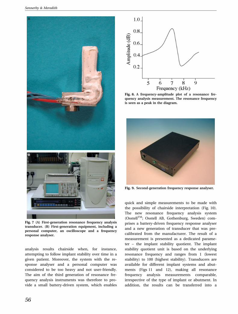
from 5 to 15 kHz with a peak amplitude of 1 V. At the
first flexural resonance of the beam, there was a
marked increase in amplitude and a change in phase
of the received signal. This can be illustrated graph-
ically as a Bode plot of frequency against amplitude
(Fig. 8).
Disadvantages with the first generation of reso-
nance frequency analysis instrumentation included a
large amount of cabling, the bulk and weight of the
equipment, and the cost of the instrument. Another
disadvantage was the sweep time of the frequency
response analyzer. A coarse frequency sweep span-
ning 5–15 kHz in 100-Hz steps with a fine sweep of 25
points around the resonance peak typically took over
1 min to perform. For these reasons, it was decided to
design a dedicated frequency response analyzer
(Fig. 9). The key design features of this instrument
were that it should be fast to use, light and portable,
completely safe for patient use, and easy to program
and to download data. These requirements were
fulfilled with the design of a dedicated frequency
response analyser, which made use of a standard
medically approved power supply unit. The instru-
ment communicated with a personal computer via a
serial port, and the personal computer was used to
both program the instrument to set frequency sweeps
and limits, and to collect and store the data on the
hard disk.
One major drawback of the first-generation and
second-generation resonance frequency analysis
instruments was that each transducer had its own
fundamental resonance frequency. Therefore, dif-
ferent transducers had to be calibrated using a
standard before measurements were comparable.
It was not possible to interpret resonance frequency
Fig. 5. A schematic showing the principles of resonance
frequency analysis. The stiffness of the transducer, implant
and bone influences the outcome as well as the effective
length of the implant above the bone crest (length).
Fig. 6. A schematic showing the
construction of the resonance fre-
quency analysis transducer.
55
Implant stability measurements using resonance frequency analysis
analysis results chairside when, for instance,
attempting to follow implant stability over time in a
given patient. Moreover, the system with the re-
sponse analyser and a personal computer was
considered to be too heavy and not user-friendly.
The aim of the third generation of resonance fre-
quency analysis instruments was therefore to pro-
vide a small battery-driven system, which enables
quick and simple measurements to be made with
the possibility of chairside interpretation (Fig. 10).
The new resonance frequency analysis system
(OsstellTM; Osstell AB, Gothenburg, Sweden) com-
prises a battery-driven frequency response analyser
and a new generation of transducer that was pre-
calibrated from the manufacturer. The result of a
measurement is presented as a dedicated parame-
ter – the implant stability quotient. The implant
stability quotient unit is based on the underlying
resonance frequency and ranges from 1 (lowest
stability) to 100 (highest stability). Transducers are
available for different implant systems and abut-
ments (Figs 11 and 12), making all resonance
frequency analysis measurements comparable,
irrespective of the type of implant or abutment. In
addition, the results can be transferred into a
A
B
Fig. 7 (A) First-generation resonance frequency analysis
transducer. (B) First-generation equipment, including a
personal computer, an oscilloscope and a frequency
response analyser.
Fig. 8. A frequency-amplitude plot of a resonance fre-
quency analysis measurement. The resonance frequency
is seen as a peak in the diagram.
Fig. 9. Second-generation frequency response analyser.
56
Sennerby & Meredith

personal computer for further analysis and storage
via a serial cable or infrared port.
The most recent version of resonance frequency
analysis is wireless, where a metal rod (a peg) is
connected to the implant by means of a screw
connection (Osstell MentorTM; Ostell AB) (Fig. 13).
The peg has a small magnet attached to its top,
which is excited by magnetic pulses from a
handheld computer. The peg vibrates in two
directions, which are approximately perpendicular
to each other. The vibration takes place in the
direction that gives the highest resonance frequency
(first mode) and in the direction that gives the
lowest resonance frequency (second mode). Thus,
two implant stability quotient values are provided,
one high and one low (Fig. 14). For instance, an
implant with buccally exposed threads may show
one low value, reflecting the lack of bone in the
buccal–lingual direction, and one high value,
reflecting good bone support in the mesial–distal
direction.
Factors influencing resonancefrequency analysis
Stiffness of the implant–bone interface
In vitro studies to measure changes in mechanical
properties and stiffness that simulate those occurring
in bone during remodelling and healing around im-
plant fixtures are difficult to perform. Although not
strictly comparable with bone, resin polymerization
offers a simple and reproducible model system for
evaluating the transducer system in relationship to
changes in stiffness. A significant increase in stiffness
accompanies the polymerization of a resin as it cures
Fig. 10. The third generation and the first commercially
available resonance frequency analysis equipment (Oss-
tellTM).
Fig. 11. Aluminium blocks representing different reso-
nance frequencies used in the calibration of the third-
generation transducers in order to measure implant
stability quotient (ISQ) units.
Fig. 13. Clinical use of a SmartpegTM and a MentorTM, the
fourth generation of the resonance frequency analysis
system.
Fig. 12. Clinical use of an OsstellTM transducer.
57
Implant stability measurements using resonance frequency analysis

and changes from a liquid or gel to a solid phase. The
frequency response of a transducer–implant system
embedded in various resins has been measured at
predetermined intervals (Fig. 15) (29).
Early clinical work indicated a relationship be-
tween bone density and primary implant stability.
Friberg et al. (18) correlated cutting resistance (i.e.
bone density) with primary stability for maxillary
implants (Fig. 16). Follow-up measurements per-
formed at the time of abutment connection (6–
8 months later) and after 1 year in function indicated
that all implants, irrespective of initial stability, ten-
ded to reach a similar level of stability. Andersson
et al. (5) examined 102 Neoss implants and found an
inverse relationship between cutting torque (bone
density) and changes in implant stability during a
study period of 12 months. They also identified a
correlation between bone quality, measured accord-
ing to Lekholm & Zarb (27), and primary stability.
Implants in soft bone with low primary stability
showed a marked increase in stability compared with
implants in dense bone (Fig. 17). In fact, implants
placed in dense type 1 and type 2 bone revealed a
slight decrease in stability, probably as a result of
marginal bone remodelling, but all implants reached
a comparable level of stability after 1 year. Similar
findings have also been reported by other researchers
(10, 11, 33, 36, 51, 52). The data indicate that the
stiffness of the implant–bone interface is high in
dense bone and low in soft bone. Moreover, the
healing and remodelling process of soft trabecular
bone seems to result in an increased stiffness of the
peri-implant bone.
The resonance frequency analysis technique has
also been used in animals to study implant healing in
normal bone (31), in grafted bone (42–44) and in
membrane-induced bone (45). In rabbits, the reso-
nance frequency increases with time as a function of
an increased stiffness resulting from new bone for-
mation and remodelling. However, if the primary
stability of an implant is very high, as can be achieved
in the dog mandible, subtle changes in stiffness may
not be evident (47, 48). In an in vitro study of human
Fig. 14. In several implant systems, the MentorTM gives
one low and one high implant stability quotient value,
reflecting the highest and the lowest level of stability of an
implant.
Fig. 15. Change of resonance frequency with time for an
implant placed in curing resin.
Fig. 16. Resonance frequency for maxillary implants
placed in different bone densities.
58
Sennerby & Meredith

bone, a positive linear correlation was found for
resonance frequency analysis and insertion torque
and for resonance frequency analysis and Hounsfield
Units, as evaluated in computed tomography scans of
the jaws (54), which lends further credence to the
ability of resonance frequency analysis to measure
the mechanical properties of bone. In an in vitro
experiment, Ito et al. (26) used three screws to sta-
bilize an implant at four different levels. The reso-
nance frequency decreased when unscrewing the
most coronal screws but not with the loss of the
more apical screws, which suggests that the marginal
region is the most important for the outcome of
resonance frequency analysis measurements. The
results of Ito et al. (26) also indicated that implant
length may not have a significant impact on reso-
nance frequency analysis measurements, a notion
that has also been espoused in in vitro (19) and in
clinical (8, 12, 40) studies.
The Osstell technique has demonstrated higher
implant stability in maxillary bone than in mandib-
ular bone (8–12, 32, 40). Also, as discussed above, a
correlation between bone quality (25) and implant
stability quotient values has been identified by sev-
eral investigators (5, 9, 12, 40), but not by all (59).
Based on resonance frequency analysis measure-
ments of 905 consecutive screw-shaped implants,
Ostman et al. (40) found primary implant stability to
be dependent on the jaw, bone density, gender, im-
plant diameter and the anterior ⁄ posterior position of
the implant. Interestingly, Ostman et al. (40) found
decreasing stability with increasing implant length.
Miyamoto et al. (32) made a similar observation. This
may be explained by the fact that some long implant
designs have a reduced diameter (negative tolerance)
in the coronal part to reduce friction heat and facil-
itate easy insertion. However, Bischof et al. (12)
found that implant position, implant length, implant
diameter and vertical position did not affect the im-
plant stability quotient values of 106 implants placed
in the maxilla and the mandible. Zix et al. (60) stud-
ied maxillary implants and reported higher implant
stability in male patients than in female patients.
Studies on one-stage and immediately loaded
implants have demonstrated an initial decrease of
implant stability, which, however, seems to reverse
after 3 months when an increase in implant stability
is usually seen (10, 21, 23, 41). The initial decrease
in implant stability is probably caused by the start
of the healing and remodelling process, which in-
cludes resorption and thereby a temporary weak-
ening of the bone, and also because of the extra
burden of implant loading during this period of
time (23). However, a recent study that used a ta-
pered implant design for immediate ⁄ early loading
did not show an initial decrease in implant stability
(15). Rather, resonance frequency analysis mea-
surements increased from implant placement to
1 year after initial loading (15). Implant design and
surface structure may have an impact on implant
stability during initial healing. In dogs, Rompen
et al. (47) showed that surfaced-modified implants
maintained stability, whilst machined implants
experienced a decrease in stability during the early
healing period. Glauser et al. (22) compared ma-
chined and oxidized implants using an immediate
loading protocol and found more decrease in sta-
bility for machined implants during the first
3 months post-loading.
Histometric correlations
Most studies have failed to show a correlation
between the degree of implant–bone contacts and
resonance frequency analysis measurements (1, 25,
31). This may relate to the nature of the test, because
the degree of bone contacts does not necessarily
reflect the stiffness of the surrounding bone. In
modern implant dentistry using moderately rough
implants, the surface is often covered by a thin layer of
bone, which is probably not important for the bio-
mechanical support of implants. Most researchers
have not found rough or smooth implant surfaces to
impact on implant stability (3, 4, 19, 48, 50), although,
as discussed above, some researchers have reported
different implant stability with different implant
surfaces (44).
Myiamoto et al. (32) observed a strong, positive
correlation between cortical bone thickness, as
Fig. 17. Implant stability quotient values for 102 implants
placed in different bone densities and followed from the
time of placement to abutment connection and to the first
annual follow-up examination. ISQ, implant stability
quotient.
59
Implant stability measurements using resonance frequency analysis

judged from computed tomography scans and initial
implant stability quotient values for 225 screw-
shaped implants placed in the maxilla and the
mandible. Similarly, Nkenke et al. (34) and Gedrange
et al. (20) found a positive correlation between the
height of the crestal cortical bone and implant sta-
bility quotient values in cadaver studies.
Distance to first bone contact ⁄ marginalbone loss
The relationship between the length of an implant
abutment and resonance frequency analysis data has
been examined in various model systems. Meredith
et al. (29) measured the frequency response of the
transducer attached to an implant fixture in an alu-
minium block using abutments of various lengths
(Fig. 18). In a dog study on peri-implant breakdown,
Sennerby et al. (48) demonstrated a negative corre-
lation between radiographic bone loss and resonance
frequency. It should be noted that marginal break-
down was initiated after healing and integration of
the implants.
Meredith et al. (30) studied 52 maxillary implants
after at least 5 years in function and revealed a
significant, positive relationship between effective
implant length (abutment length + bone loss) and
resonance frequency. The study implants showed a
similar degree of stability after 5 years of function
(30). In a study on one-stage implants in dense
mandibular bone, a small, but significant, decrease in
stability was detected over a 15-week period, which
was probably caused by marginal bone loss and an
increased exposure of the implant above the bone
crest (17).
Turkyilmaz et al. (55) found a negative correla-
tion between increased marginal bone loss around
mandibular implants and decreased implant sta-
bility over the first 6 months following implant
placement. No such correlation was observed
between the 6-month and the 12-month study
period (55). The authors suggested that the effect of
bone loss was compensated for by an increased
interfacial stiffness resulting from bone formation
and remodelling. However, Fischer et al. (15) found
no correlation between marginal bone loss and
resonance frequency analysis measurements during
a 1-year period. The ongoing healing process
may have counteracted and masked the effect of
marginal bone loss. However, after 3 and 5 years,
when healing must be regarded as being complete,
the same research group found a strong, positive
correlation between marginal bone resorption and
low implant stability quotient values. This is in line
with Meredith et al. (30), who suggested that vari-
ations in implant stability after 5 years in function
could be explained by differences in marginal bone
height.
Turkyilmaz et al. (56) demonstrated a negative
correlation between exposed implant height and
implant stability quotient values for implants placed
in fresh extraction sockets in human jaws. The au-
thors proposed using the resonance frequency anal-
ysis technique to monitor the healing of implants in
extraction sockets.
Orientation of the resonance frequencyanalysis transducer
The orientation of the transducer influences the
resonance frequency analysis measurements. Veltri
et al. (59) and Fischer et al. (14, 16) found that
implant stability quotient values increased by
approximately 10 units when performing measure-
ments with the transducer parallel to, rather than
perpendicular to, the alveolar crest. The implant–
bone complex probably displays varying degrees of
stiffness in different load directions. Low implant
stability quotient values obtained in the buccal–
palatal direction are a reflection of thinner bone
than in the mesial–distal direction. According to the
manufacturer, the new wireless resonance fre-
quency analysis technique (MentorTM; Osstell AB)
measures the highest and the lowest resonance
frequency whenever the difference exceeds 3 im-
plant stability quotient units. This may explain the
observed difference in stability readings between
the new and the old resonance frequency analysis
Fig. 18. The relationship between resonance frequency
and the effective length of the implant above the bone
crest.
60
Sennerby & Meredith

technique. Valderrama et al. (57) found that the
two resonance frequency analysis techniques
can differ by up to 10 implant stability quotient
units, with higher stability values obtained in
the mesial–distal direction with the wireless
technique and lower values obtained in the
buccal–palatal direction with the old technique. The
specific orientation of the old resonance frequency
analysis transducer may be the cause of the
different resonance frequency analysis readings.
Fig. 19 shows the results of stability measurements
in 12 different transducer directions using the old
resonance frequency analysis instrument and a
direction-dependent transducer. Also, the new res-
onance frequency analysis technique, as shown in
Fig. 19, yielded two different values, one recording
the highest and one recording the lowest implant
stability quotient value. In sum, it needs to be
appreciated that implant resonance frequency
analysis stability readings vary, depending on which
direction the measurements are made using the
transducer.
The utility of the resonancefrequency analysis technique topredict implant failure
Friberg at al. (17), in 1999, evaluated 75 one-stage
implants in the edentulous mandible by means of
repeated resonance frequency analysis measure-
ments. One implant showed a decreasing stability
from week 2 to week 15, when the implant was found
to be clinically mobile. In a second patient, three of
five implants showed a marked decrease in stability
from week 2 to week 6, which corresponded to the
period of implant loading with a relined denture.
After asking the patient to refrain from wearing the
denture, the implant stability increased for two im-
plants and was maintained at the same level for one
implant (Fig. 20). The same research group followed
56 implants in the maxilla of nine patients and
demonstrated, for all but two failing implants, an
increase in implant stability from the time of place-
ment to abutment connection (18). The data point to
an increase in stiffness of the implant–bone complex
over time, except for soft-tissue-encapsulated failed
implants.
In an immediate loading study, Glauser et al. (23)
monitored the resonance frequency analysis stability
of 81 implants from placement to 1 year in function.
A total of nine implants failed during the 1-year
observation period. All implants showed a high de-
gree of initial stability, around implant stability
quotient 70, but the group of future failures showed a
continuous decrease in implant stability. After
1 month, the mean implant stability quotient value of
52 was statistically lower for the group of future
failures than for the successful implants, which
Fig. 19. Resonance frequency analysis measurements
of an implant in 12 directions using an OsstellTM
instrument. The red and yellow circles indicate the
results from one measurement using the new wire-
less MentorTM technique. It is obvious that implant
stability varies with the direction of the applied load and
that the new resonance frequency analysis technique
indentifies the lowest and the highest levels of implant
stability.
Fig. 20. Implant stability in one patient with five non-
submerged implants in the mandible. Three implants
showed a marked decrease of stability, which, however,
recovered after unloading of the removable denture.
61
Implant stability measurements using resonance frequency analysis

showed an implant stability quotient of 68. Also,
implant stability quotient values of 49–58 were
associated with an 18.2% risk of failure. Evidently,
the lower the implant stability quotient value after
1 month of immediate loading, the higher the risk for
future failure. Some of the failing implants may have
been rescued by unloading and allowing a period of
healing. However, the study of Glauser et al. (23)
analyzed the resonance frequency analysis mea-
surements retrospectively and no intervention could
be taken chairside. In a follow-up study on implants
placed in extraction sockets and subjected to
immediate/early loading, Vanden Boagerde and
co-workers (58) demonstrated rescue of one implant
based on resonance frequency analysis measure-
ments. This implant showed a significant drop from
67 ISQ to 53 ISQ during the first six weeks. The
implant was unloaded and recovered to an ISQ value
of 72 after 6 months.
Sjostrom et al. (52) found lower primary stability
for 17 implants (implant stability quotient 54.6) that
failed during the first year of function compared with
195 implants (implant stability quotient 62.0) that
were successful installed in grafted maxillae. Nedir
et al. (33) compared immediately loaded implants
with implants loaded after 3 months of healing and
concluded that the resonance frequency analysis
technique did not reliably identify mobile implants.
However, implant stability could be reliably deter-
mined for implants with an implant stability quotient
of more than 47. One explanation for not detecting
some mobile implants may be a result of the nature
of the resonance frequency analysis technique, which
measures stability as a function of stiffness. Clinically
mobile implants display an exceptionally low stiff-
ness, which prevents the resonance frequency anal-
ysis system from identifying the first resonance fre-
quency, and which therefore records a falsely high
implant stability quotient value corresponding to the
second resonance frequency (28).
Huwiler et al. (24) followed 17 implants with re-
peated resonance frequency analysis measurements
for up to 12 weeks after implant surgery (24). One
implant failed and its implant stability quotient value
decreased from 68 to 45. As implant mobility oc-
curred at low implant stability quotient values, the
authors concluded that the resonance frequency
analysis system cannot be used to predict implant
failure.
Fischer et al. (15) studied the stability of 53 im-
plants during a period of 1 year (15). The implants
supported single crowns (n = 16) or partial bridges
(n = 16) in the maxilla placed at the time of, or within
16 days of, implant surgery. The average primary
stability of all implants after surgery was 63.3 implant
stability quotients, and one failed implant showed a
value of 56 implant stability quotients, which was the
fifth lowest value of the 53 implants.
Fischer (14) performed resonance frequency analy-
sis measurements in 24 patients with 139 maxillary
implants at 3 and 5 years following implant surgery.
Four implants were lost during the third to the fifth
year. At year 3, the failing implants showed lower im-
plant stability quotient values than the average im-
plant (i.e. 44 implant stability quotients, 53 implant
stability quotients, 54 implant stability quotients and
54 implant stability quotients vs. an average of 57.7
implant stability quotients for all other implants in the
study). An assessment of the risk for implant failure
showed that implant stability quotient values below
44, 53 and 54 were associated with failure rates of
100%, 6.7% and 9.5%, respectively. None of 97 im-
plants with implant stability quotient values higher
than 54 failed from study year 3 to study year 5.
Possible clinical implications
The resonance frequency analysis technique has the
potential to provide clinically relevant information
about the state of the implant–bone interface at any
stage of the treatment. The question is how to benefit
most from information obtained by a single reso-
nance frequency analysis measurement in clinical
practice. To date, there is a lack of studies that
document clear clinical benefits from therapeutic
decisions based on resonance frequency analysis
measurements. Obviously, one major goal in implant
dentistry is to avoid implant failure. Although the
failure rate of implants used in two-stage proce-
dures is rather low, it is likely that higher failure
rates are associated with immediate loaded or
grafted implants. Moreover, increasingly more
implant procedures are being performed by relatively
inexperienced clinicians, who will be confronted with
a variety of complications during their learning
curve. As implant failures are often related to bio-
mechanical factors, an assessment of implant stabi-
lity may significantly lower the risk of failure. Studies
have shown that high resonance frequency analysis
values are indicative of a successful implant treat-
ment with a small risk for future failure. Conversely,
low or decreasing resonance frequency analysis
values point to an increased risk for implant com-
plications, although the exact resonance frequency
analysis threshold values have yet to be identified.
62
Sennerby & Meredith

It appears that implants of every system will, with
time, approach a similar level of stability, which for
Branemark type implants seems to be an implant
stability quotient of 65–75, and for Straumann type
implants seems to be an implant stability quotient of
55–65. It seems reasonable to assume that this degree
of stability at any time during the lifetime of an im-
plant would indicate a safe level of stability. An im-
plant stability quotient value below 55 (Branemark)
or 45 (Straumann) should be regarded as a warning
sign, and measures to increase implant stability
should be considered. Primary stability can be im-
proved by modifying the surgical technique and by
selecting a wider, longer or tapered implant. For
instance, the use of thinner drills and wider and
tapered implants will increase primary implant sta-
bility (35). The current trend is to use short healing
periods also for two-stage procedures, which, how-
ever, may result in inadequate healing for implants in
soft bone. Extending the healing period after implant
placement constitutes a simple approach to gain
additional stability. A low implant stability quotient
value at a postloading examination may indicate
disintegration of the implant–bone interface and
ongoing failure (Fig. 21). In such a case, the
crown ⁄ bridge construction of the implant may be
removed in order to determine the stability of the
fixture. An unloaded healing period of 6 weeks or
longer may give the implant sufficient time to regain
stability. A declining implant stability quotient value
A B
C
E
D
Fig. 21. (A) Resonance frequency analysis measurements
from implant placement to 22 months of loading. ISQ,
implant stability quotient. (B) Of the three implants in the
posterior maxilla, L1 and L2 exhibited increased stability,
whereas L3 showed no stability increase. (C) At the first
annual follow-up, the implant in the first molar region
was clinically mobile and the other two implants showed
extensive marginal bone loss as a result of misfit, soft bone
and overload. These two implants showed a marked de-
crease in implant stability quotient owing to the marginal
bone loss and disintegration. (D) The bridge was short-
ened and loading was controlled. A new implant was
placed in conjunction with a membrane-elevation proce-
dure. Implant stability had increased. (E) The new final
prosthetic construction including the new implant. L1 and
L2 showed increasing stability, even though some mar-
ginal bone loss remained.
63
Implant stability measurements using resonance frequency analysis

can also be the result of ongoing marginal bone
resorption, and radiographs should be obtained to
assess the status of the periodontal bone. For a
Branemark type implant, a 10 unit drop from implant
stability quotient 75 to 65 may not be as alarming as a
decline from implant stability quotient 60 to 50. The
manufacturer advises that a decrease of about 3 im-
plant stability quotient units ⁄ mm can be expected.
With peri-implantitis, implant stability can still be
high, but the future of the implant is threatened by
ongoing and untreated marginal bone loss. In sum-
mary, the resonance frequency analysis technique
may be used in follow-up examinations of implants,
and only implants with low or decreasing implant
stability quotient values need to be radiographed.
One drawback with this approach is that prosthetic
constructions need to be removed in order to per-
form the resonance frequency analysis measure-
ments.
The resonance frequency analysis technique may
be useful for assessing immediate loading implants
during the various stages of treatment. For instance, a
certain implant stability quotient value can be used
as an inclusion criterion for immediate loading of
implants. Ostman et al. (38, 39) reported low failure
rates when using implant stability quotient 60 as an
inclusion criterion for immediate loaded implants in
totally edentulous maxillae and in posterior mandi-
bles. The authors of the present study find the reso-
nance frequency analysis technique to be helpful in
deciding when to replace an immediately loaded
temporary prosthesis with a permanent prosthesis
after implant placement. Values above implant sta-
bility quotient 65 indicate a favourable response to
immediate loading, whilst low implant stability
quotient values may be indicative of overload and
ongoing failure. In such cases, unloading and per-
haps placement of additional implants before
inserting the permanent prosthesis should be con-
sidered.
Finally, the resonance frequency analysis tech-
nique may serve as a valuable tool for documenting
the clinical outcome of implant treatments. This may
be particularly important in a medico-legal setting.
Also, for the implant surgeon, who receives referred
patients for implant placement for later prosthetic
treatment by the referring dentist, the resonance
frequency analysis technique may help to assure the
referring dentist and the patient of sufficient implant
stability prior to commencing the prosthetic treat-
ment phase. In other words, the resonance frequency
analysis technique can be used to provide a �finger-
print� of inserted implants.
Conclusions
The resonance frequency analysis technique can
supply clinically relevant information about the state
of the implant–bone interface at any stage of the
treatment or at follow-up examinations. The reso-
nance frequency analysis technique evaluates im-
plant stability as a function of the stiffness of the
implant–bone interface and is influenced by factors
such as bone density, jaw healing time and exposed
implant height above the alveolar crest. Studies
indicate that implants with high implant stability
quotient values during follow-up examinations are
successfully integrated, whilst low and decreasing
implant stability quotient values may be a sign of
ongoing implant failure and ⁄ or marginal bone loss.
However, more clinical studies and case reports are
needed to formulate clear guidelines for clinical use
of the resonance frequency analysis technique.
References
1. Akca K, Chang TL, Tekdemir I, Fanuscu MI. Biomechanical
aspects of initial intraosseous stability and implant design:
a quantitative micro-morphometric analysis. Clin Oral
Implants Res 2006: 17: 465–472.
2. Albrektsson T, Zarb GA. Current interpretations of the
osseointegrated response: clinical significance. Int J Pros-
thodont 1993: 6: 95–105.
3. Al-Nawas B, Groetz KA, Goetz H, Duschner H, Wagner W.
Comparative histomorphometry and resonance frequency
analysis of implants with moderately rough surfaces in
a loaded animal model. Clin Oral Implants Res 2007: 18:
1–8.
4. Al-Nawas B, Hangen U, Duschner H, Krummenauer F,
Wagner W. Turned, machined versus double-etched dental
implants in vivo. Clin Implant Dent Relat Res 2007: 9:
71–78.
5. Andersson P, Verrocchi D, Viinamaki R, Sennerby L. A one-
year clinical, radiographic and RFA study of Neoss im-
plants. Appl Osseointegration Res 2008: 6: 23–26.
6. Aparicio C, Lang NP, Rangert B. Validity and clinical sig-
nificance of biomechanical testing of implant ⁄ bone
interface. Clin Oral Implants Res. 2006: 17: 2–7.
7. Attard NJ, Zarb GA. Immediate and early implant loading
protocols: a literature review of clinical studies. J Prosthet
Dent 2005: 94: 242–258.
8. Balleri P, Cozzolino A, Ghelli L, Momicchioli G, Varriale A.
Stability measurements of osseointegrated implants using
Osstell in partially edentulous jaws after 1 year of loading: a
pilot study. Clin Implant Dent Relat Res 2002: 4: 128–132.
9. Balshi SF, Allen FD, Wolfinger GJ, Balshi TJ. A resonance
frequency analysis assessment of maxillary and mandibu-
lar immediately loaded implants. Int J Oral Maxillofac
Implants 2005: 20: 584–594.
10. Barewal RM, Oates TW, Meredith N, Cochran DL. Reso-
nance frequency measurement of implant stability in vivo
64
Sennerby & Meredith

on implants with a sandblasted and acid-etched surface.
Int J Oral Maxillofac Implants 2003: 18: 641–651.
11. Becker W, Sennerby L, Bedrossian E, Becker BE, Lucchini
JP. Implant stability measurements for implants placed at
the time of extraction: a cohort, prospective clinical trial.
J Periodontol 2005: 76: 391–397.
12. Bischof M, Nedir R, Szmukler-Moncler S, Bernard JP,
Samson J. Implant stability measurement of delayed and
immediately loaded implants during healing. Clin Oral
Implants Res 2004: 15: 529–539.
13. Esposito M, Hirsch JM, Lekholm U, Thomsen P. Biological
factors contributing to failures of osseointegrated oral im-
plants. I. Success criteria and epidemiology. Eur J Oral Sci
1998: 106: 721–764.
14. Fischer K. On immediate ⁄ early loading of implant-
supported prostheses in the maxilla. Thesis, Sweden:
Gothenburg University, 2008.
15. Fischer K, Backstrom M, Sennerby L. Immediate and early
loading of oxidized tapered implants in the partially
edentulous maxilla. A one-year prospective clinical,
radiographic and resonance frequency analysis study. Clin
Implant Dent Relat Res 2008: in press
16. Fischer K, Stenberg T, Hedin M, Sennerby L. Five-year re-
sults from a randomized, controlled trial on early and de-
layed loading of implants supporting full-arch prostheses
in the edentulous maxilla. Clin Oral Implants Res 2008: in
press
17. Friberg B, Sennerby L, Linden B, Grondahl K, Lekholm U.
Stability measurements of one-stage Branemark implants
during healing in mandibles. A clinical resonance fre-
quency study. Int J Oral Maxillofac Surg 1999: 28: 266–272.
18. Friberg B, Sennerby L, Meredith N, Lekholm U. A com-
parison between cutting torque and resonance frequency
measurements of maxillary implants. A 20-month clinical
study. Int J Oral Maxillofac Surg 1999: 28: 297–303.
19. Froberg KK, Lindh C, Ericsson I. Immediate loading of
Branemark System Implants: a comparison between Ti-
Unite and turned implants placed in the anterior mandible.
Clin Implant Dent Relat Res 2006: 8: 187–197.
20. Gedrange T, Hietschold V, Mai R, Wolf P, Nicklisch M,
Harzer W. An evaluation of resonance frequency analysis
for the determination of the primary stability of ortho-
dontic palatal implants. A study in human cadavers. Clin
Oral Implants Res 2005: 16: 425–431.
21. Glauser R, Lundgren AK, Gottlow J, Sennerby L, Portmann
M, Ruhstaller P, Hammerle CH. Immediate occlusal load-
ing of Branemark TiUnite implants placed predominantly
in soft bone: 1-year results of a prospective clinical study.
Clin Implant Dent Relat Res 2003: 5: 47–56.
22. Glauser R, Portmann M, Ruhstaller P, Lundgren AK,
Hammerle C, Gottlow J. Stability measurements of imme-
diately loaded machined and oxidized implants in the
posterior maxilla. A comparative study using resonance
frequency analysis. Appl Osseointegration Res 2001: 2: 27–
29.
23. Glauser R, Sennerby L, Meredith N, Ree A, Lundgren A,
Gottlow J, Hammerle CH. Resonance frequency analysis of
implants subjected to immediate or early functional
occlusal loading. Successful vs. failing implants. Clin Oral
Implants Res 2004: 15: 428–434.
24. Huwiler MA, Pjetursson BE, Bosshardt DD, Salvi GE, Lang
NP. Resonance frequency analysis in relation to jawbone
characteristics and during early healing of implant instal-
lation. Clin Oral Implants Res 2007: 18: 275–280.
25. Ito Y, Sato D, Yoneda S, Ito D, Kondo H, Kasugai S. Rele-
vance of resonance frequency analysis to evaluate dental
implant stability: simulation and histomorphometrical
animal experiments. Clin Oral Implants Res 2007: 18: 1–6.
26. Ivanoff CJ, Sennerby L, Lekholm U. Reintegration of
mobilized titanium implants. An experimental study in
rabbit tibia. Int J Oral Maxillofac Surg 1997: 26: 310–315.
27. Lekholm U, Zarb GA. Patient selection and preparation. In:
Branemark PI, Zarb GA, Albrektsson T, editors. Tissue-
integrated prostheses: osseointegration in clinical dentistry.
Chicago: Quintessence, 1985: 199–209.
28. Meredith N. Assessment of implant stability as a prognostic
determinant. Int J Prosthodont 1998: 11: 491–501.
29. Meredith N, Alleyne D, Cawley P. Quantitative determina-
tion of the stability of the implant-tissue interface using
resonance frequency analysis. Clin Oral Implants Res 1996:
7: 261–267.
30. Meredith N, Book K, Friberg B, Jemt T, Sennerby L. Reso-
nance frequency measurements of implant stability in vivo.
A cross-sectional and longitudinal study of resonance fre-
quency measurements on implants in the edentulous and
partially dentate maxilla. Clin Oral Implants Res 1997: 8:
226–233.
31. Meredith N, Shagaldi F, Alleyne D, Sennerby L, Cawley P.
The application of resonance frequency measurements to
study the stability of titanium implants during healing in
the rabbit tibia. Clin Oral Implants Res 1997: 8: 234–243.
32. Miyamoto I, Tsuboi Y, Wada E, Suwa H, Iizuka T. Influence
of cortical bone thickness and implant length on implant
stability at the time of surgery – clinical, prospective, bio-
mechanical, and imaging study. Bone 2005: 37: 776–780.
33. Nedir R, Bischof M, Szmukler-Moncler S, Bernard JP,
Samson J. Predicting osseointegration by means of implant
primary stability. Clin Oral Implants Res 2004: 15: 520–528.
34. Nkenke E, Hahn M, Weinzierl K, Radespiel-Troger M,
Neukam FW, Engelke K. Implant stability and histo-
morphometry: a correlation study in human cadavers using
stepped cylinder implants. Clin Oral Implants Res 2003: 14:
601–609.
35. O�Sullivan D, Sennerby L, Meredith N. Measurements
comparing the initial stability of five designs of dental
implants: a human cadaver study. Clin Implant Dent Relat
Res 2000: 2: 85–92.
36. Olsson M, Urde G, Andersen JB, Sennerby L. Early loading
of maxillary fixed cross-arch dental prostheses supported
by six or eight oxidized titanium implants: results after
1 year of loading, case series. Clin Implant Dent Relat Res
2003: 5: 81–87.
37. Ostman PO. Immediate ⁄ early loading of dental implants.
Clinical documentation and presentation of a treatment
concept. Periodontol 2000 2008: 47: 90–112.
38. Ostman PO, Hellman M, Sennerby L. Direct implant
loading in the edentulous maxilla using a bone density-
adapted surgical protocol and primary implant stability
criteria for inclusion. Clin Implant Dent Relat Res 2005: 7:
S60–S69.
39. Ostman PO, Hellman M, Sennerby L. Occlusal loading of
implants in the partially edentate mandible: A prospective
1-year radiographic and 4-year clinical study. Int J Oral
Maxillofac Implants 2008: in press
65
Implant stability measurements using resonance frequency analysis

40. Ostman PO, Hellman M, Wendelhag I, Sennerby L. Reso-
nance frequency analysis measurements of implants at
placement surgery. Int J Prosthodont 2006: 19: 77–83. Dis-
cussion 84.
41. Rao W, Benzi R. Single mandibular first molar implants
with flapless guided surgery and immediate function:
preliminary clinical and radiographic results of a pro-
spective study. J Prosthet Dent 2007: 97: S3–S14.
42. Rasmusson L, Meredith N, Cho IH, Sennerby L. The
influence of simultaneous versus delayed placement on the
stability of titanium implants in onlay bone grafts. A his-
tologic and biomechanic study in the rabbit. Int J Oral
Maxillofac Surg 1999: 28: 224–231.
43. Rasmusson L, Meredith N, Kahnberg KE, Sennerby L. Sta-
bility assessments and histology of titanium implants
placed simultaneously with autogenous onlay bone in the
rabbit tibia. Int J Oral Maxillofac Surg 1998: 27: 229–235.
44. Rasmusson L, Meredith N, Kahnberg KE, Sennerby L. Ef-
fects of barrier membranes on bone resorption and im-
plant stability in onlay bone grafts. An experimental study.
Clin Oral Implants Res 1999: 10: 267–277.
45. Rasmusson L, Meredith N, Sennerby L. Measurements of
stability changes of titanium implants with exposed
threads subjected to barrier membrane induced bone
augmentation. An experimental study in he rabbit tibia.
Clin Oral Implants Res 1997: 8: 316–322.
46. Rompen E, DaSilva D, Lundgren AK, Gottlow J, Sennerby L.
Stability measurements of a double-threaded titanium
implant design with turned or oxidised surface. Appl
Osseointegration Res 2000: 1: 18–20.
47. Sennerby L, Meredith N. Resonance frequency analysis:
measuring implant stability and osseointegration. Com-
pend Contin Educ Dent 1998: 500: 502.
48. Sennerby L, Persson LG, Berglundh T, Wennerberg A,
Lindhe J. Implant stability during initiation and resolution
of experimental periimplantitis: an experimental study in
the dog. Clin Implant Dent Relat Res 2005: 7: 136–140.
49. Sennerby L, Roos J. Surgical determinants of clinical suc-
cess of osseointegrated oral implants. A review of the lit-
erature. Int J Prosthodont 1998: 11: 408–420.
50. Shalabi MM, Wolke JG, Jansen JA. The effects of implant
surface roughness and surgical technique on implant fix-
ation in an in vitro model. Clin Oral Implants Res 2006: 17:
172–178.
51. Sjostrom M, Lundgren S, Nilson H, Sennerby L. Monitoring
of implant stability in grafted bone using resonance fre-
quency analysis. A clinical study from implant placement
to 6 months of loading. Int J Oral Maxillofac Surg 2005: 34:
45–51.
52. Sjostrom M, Sennerby L, Nilson H, Lundgren S. Recon-
struction of the atrophic edentulous maxilla with free
iliac crest grafts and implants: a 3-year report of a pro-
spective clinical study. Clin Implant Dent Relat Res 2007:
9: 46–59.
53. Sullivan DY, Sherwood RL, Collins TA, Krogh PH. The re-
verse-torque test: a clinical report. Int J Oral Maxillofac
Implants 1996: 11: 179–185.
54. Turkyilmaz I, Sennerby L, McGlumphy E, Tozum TF. Bio-
mechanical aspects of primary implant stability: A human
cadaver Study. Clin Implant Dent Relat Res 2008: in press
55. Turkyilmaz I, Sennerby L, Tumer C, Yenigul M, Avci M.
Stability and marginal bone level measurements of un-
splinted implants used for mandibular overdentures: a 1-
year randomized prospective clinical study comparing
early and conventional loading protocols. Clin Oral Im-
plants Res 2006: 17: 501–505.
56. Turkyilmaz I, Sennerby L, Yilmaz B, Bilecenoglu B, Ozbek
EN. Influence of defect depth on RFA and insertion torque
values for implants placed in fresh extraction sockets. A
human cadaver study. Clin Implant Dent Relat Res 2008: in
press
57. Valderrama P, Oates TW, Jones AA, Simpson J, Schoolfield
JD, Cochran DL. Evaluation of two different resonance
frequency devices to detect implant stability: a clinical trial.
J Periodontol 2007: 78: 262–272.
58. Vanden Bogaerde L, Rangert B, Wendelhag I. Immediate/
early function of Branemark System Ti Unite implants in
fresh extraction sockets in maxillae and posterior mandi-
bles. An 18-month prospective clinical study. Clin Implant
Dent Relat Res 2005: 7(suppl. 1): 121–130.
59. Veltri M, Balleri P, Ferrari M. Influence of transducer
orientation on Osstell stability measurements ofosseo-
integrated implants. Clin Implant Dent Relat Res 2007: 9:
60–64.
60. Zix J, Kessler-Liechti G, Mericske-Stern R. Stability mea-
surements of 1-stage implants in the maxilla by means of
resonance frequency analysis: a pilot study. Int J Oral
Maxillofac Implants 2005: 20: 747–752.
66
Sennerby & Meredith