imperial journal of interdisciplinary research (ijir) vol ... · and fuzzy logic based mppt...
TRANSCRIPT

Imperial Journal of Interdisciplinary Research (IJIR) Vol-2, Issue-10, 2016 ISSN: 2454-1362, http://www.onlinejournal.in
Imperial Journal of Interdisciplinary Research (IJIR) Page 1100
Advanced Hybrid Wind-Solar Power System with Maximum Power Point
Tracking Algorithms
N. Bharath1 & R. Srinivasarao2 1PG Student [Power Systems], Dept. of EEE, Gokul Group of Institutions, Bobbili, A.P – 535 568
India. 2Assistant Professor, Dept. of EEE, Gokul Group of Institutions, Bobbili, A.P – 535 568 India.
Abstract: The requirement of production of electricity from renewable energy sources like wind and solar energy increases rapidly for 21st century needs. This paper reports the development of wind/photovoltaic power generation system and also describes the Wind-Solar Hybrid system for supplying electricity to the Load and describe various MPPT techniques namely Perturb and Observe(P&O), Incremental Conductance(INC) and Fuzzy Logic based MPPT controller and their performance. This paper presents modelling, simulation, and performance study of Hybrid generation system with PI and MPPT controller. The Wind power generation system uses Wind Turbine (WT), a Permanent Magnet Synchronous Generator (PMSG), a three phase controlled Rectifier Bridge with PI controller, a dc bus with a capacitor and a current regulated PWM voltage source inverter. The PV cell model is developed including the effects of changing solar irradiation and temperature and Maximum power from PV cell is obtained by using MPPT controller. Simulation results of Hybrid system using various MPPT techniques are provided. Keywords: Wind power generation system, Solar PV system, PI controller, MPPT Techniques.
I. INTRODUCTION Without a doubt renewable energy systems present unique [1] opportunities for greater fuel diversity, security and geographical dispersion of supply. The rapid space of the technical and commercial development of renewable energies continues to reduce costs and increase the number of both equipment suppliers and plant operators. As conventional fossil-fuel energy sources diminish and world‟s environmental concern about acid deposition and global warming increases, renewable energy sources (solar, wind, tidal and geothermal, etc.,) are attracting more attention as
alternative energy sources. Among the renewable energy sources wind and solar photovoltaic (PV) energy has been widely utilized in[1] small-sized applications. It is also the most promising candidate for research and development for large-scale uses as the fabrication of less-costly photovoltaic devices becomes a reality. The wind energy has been considered as one of the significant renewable energy sources in recent years. Wind energy can be [2] transformed to electric energy using a wind turbine and an electric generator. In wind-energy production application of PMSG has received much attention compared to other electric generators, because of its property of self-exciting, which allows an operation at a high power factor and efficiency with the development in permanent magnetic materials in recent years, the performance of PMSG based wind turbine systems has been improved and they are widely used. They can also operate in a relatively wide range of wind speeds. The PV array power and current characteristics are highly nonlinear [3] and are affected by the irradiance and temperature variation. Therefore, a maximum power-point tracker (MPPT) is required to handle such problems and ensure that PV system is operating at the maximum power point (MPP). The existing techniques vary in simplicity, accuracy, time response, popularity, cost and other technical aspect. The voltage base MPP tracking method uses the fact that ratio between the maximum power voltage and the open circuit voltage under different weather conditions, are [3] linearly proportional. The MPPT techniques like Perturb and Observe(P&O), Incremental conductance and Fuzzy Logic Controller are widely using for tracking maximum power. Among the MPPT methods, hill climbing/P&O are the commonly used algorithms because of simplicity, ease of implementation, and low cost. Hill climbing works by perturbing the PV array

Imperial Journal of Interdisciplinary Research (IJIR) Vol-2, Issue-10, 2016 ISSN: 2454-1362, http://www.onlinejournal.in
Imperial Journal of Interdisciplinary Research (IJIR) Page 1101
system by changing the power converter duty cycle and observing its impact on the PV array output power, and then deciding the new direction of the duty cycle to extract maximum power. The incremental conductive method is widely used because of implementation simplicity and high tracking efficiency. The method is based on the derivative of [3] power over voltage being zero at the MPP, positive on the left of the MPP, and negative on the right. Complex computation is required to give good performance under rapidly varying weather conditions. Moreover, the tracking time is relatively long since the step size is turned to be small enough to reach the desired MPP. The Fuzzy-Logic Controller (FLC) has been introduced [3]to evaluate P&O or hill-climbing algorithm drawbacks. In this paper a PV-Wind hybrid system is presented that can supply electricity to a load. The aim of this study is to introduce the local PV-Wind hybrid system is connected to the load. In
this paper a detailed dynamic model, control and simulation of PV/WT hybrid power generation system is proposed. Modelling and simulation are implemented using MATLAB/SIMULIMK and SIMPOWER system software packages to verify the effectiveness of the proposed system.
II. WIND TURBINE CHARACTERISTICS AND
MODELLING In order capture the maximal wind energy, it is necessary to install the power electronic devices between WTG and the load where the frequency is constant. The input of a wind turbine is the wind and the output is the mechanical power turning the generator rotor. The block diagram of the load connected wind based system driven by PMSG[7] as shown in Fig.1
Fig.1 The block diagram of wind energy system
P = 0.5ρACp(λ, β)Vw^3 For a variable speed wind turbine, the output mechanical power available from a end turbine could be expressed as[3] λ = ωmR /Vw Where P = power in watt, ρ = air density, A = rotor swept area, Vw = wind speed in m/sec, Cp = coefficient of performance. The relation between rotor speed and [3] wind speed can be given by (2)
Where R = rotor radius, ωm = rotor speed in rad/sec, λ = tip speed ratio(TSR) = ratio [3]between the linear speed of the tip of the blade with respect to the wind speed. The wind turbine torque on the shaft can be calculated from the power Tm = Pm /Wm = 0.5ρπR^5(Wm / λ)^3Cp(λ, β) (3) Cp(λ, β )= 0.5176||

Imperial Journal of Interdisciplinary Research (IJIR) Vol-2, Issue-10, 2016 ISSN: 2454-1362, http://www.onlinejournal.in
Imperial Journal of Interdisciplinary Research (IJIR) Page 1102
Where Cp(α,β) – performance coefficient of the turbine, ω - turbine [3]angular velocity(rad/sec), β – Blade pitch angle(deg), λ - Tip speed of the rotor blade tip speed to wind speed. Equation of the wind turbine is given as: Tm −Te − F * w = Jdω/ dt (6) The Cp - λ characteristics for different values of the pitch angle β, are illustrated in Fig.2 for 12m/s
The maximum value of Cp(Cpmax=0.8) is achieved for β=0 and for λ=1. This particular value of λ is defined as the nominal value. The simulated system parameters are listed in the table-1.
A model of photovoltaic cell is shown in Fig.3. From the circuit it can be seen that[4] the current produced by the solar cell is equal to that produced by the current source minus that which flows through the shunt resistor.
Using the equivalent circuit of a solar cell (Fig:3) and the pertinent equations, the non-linear (I-V) characteristics of a solar cells is given by[4] the following equation:

Imperial Journal of Interdisciplinary Research (IJIR) Vol-2, Issue-10, 2016 ISSN: 2454-1362, http://www.onlinejournal.in
Imperial Journal of Interdisciplinary Research (IJIR) Page 1103
Where „I’ is the PV array output current (A), „V’ is the PV array output voltage (V).
Where, Ns is the number of series cell, K is the Boltzmann‟s constant in J/K, q is the electric charge. The photocurrent Iph depends [4]on the solar radiation and the cell temperature as stated in the following.
Where Iscr is the PV array short circuit current at reference temperature and radiation (A), Ki is the short circuit current temperature coefficient (A/K) and G is the solar radiation (mW/cm^2). The Fig.4 below gives the characteristics I-V and P-V curve for fixed level of solar irradiation and temperature
The simulated system parameters are listed in table 2.

Imperial Journal of Interdisciplinary Research (IJIR) Vol-2, Issue-10, 2016 ISSN: 2454-1362, http://www.onlinejournal.in
Imperial Journal of Interdisciplinary Research (IJIR) Page 1104
IV. MPPT ALGORITHM TECHNIQUES
A. PERTURB AND OBSERVE METHOD
In this method the controller adjusts the voltage by a small amount from the array and measure power, if the power increases further adjustments in that direction are tried until power no longer increases. This is called perturb and observe [5]method and it is most common, although this method can result in oscillations of power o/p. It is referred to as hill
climbing algorithm method because it depends on the rise of the curve of power against voltage below maximum power point and the fall above that point perturb and observe is the most commonly used MPPT method due to its ease of implementation. P&O method may result in top level efficiency , provide that a proper predictive and adaptive hill climbing strategy is adopted. The fig.6 shows flowchart for P&O method,
B. INCREMENTAL CONDUCTANCE
ALGORITHM In the incremental conductance method, the controller measures incremental changes in array current and voltage to predict the effect of a[5] voltage change. This method requires more computation in the controller, but can track changing conditions more rapidly than the perturb and observe method. Like the P&O algorithm, it can produce oscillations in a power o/p. This method utilizes the incremental conductance
(di/dv) of the PV array to compute the sign of the change in power with respect to voltage (dp/dv). The incremental conductance method computes the maximum power point by comparison of the incremental conductance (I∆/V∆) to the array conductance (I/V). When these two are the same (I/V = I∆/V∆), the o/p voltage is the MPP voltage. The controller maintains this voltage until the irradiation changes and the process is repeated. The Fig.7 shows flowchart for incremental conductance method,

Imperial Journal of Interdisciplinary Research (IJIR) Vol-2, Issue-10, 2016 ISSN: 2454-1362, http://www.onlinejournal.in
Imperial Journal of Interdisciplinary Research (IJIR) Page 1105
Since the PV array exhibits a non-linear current-voltage (or) power-voltage characteristics, its maximum power point varies with [6]the insulation and temperature. By the knowledge based fuzzy rules, fuzzy control can track maximum power
point. The disadvantage of this control is the high cost of implementation owing to complex algorithms that usually need a DSP as their computing platform. Fig:8 shows PV system with FUZZY MPPT controller.
We choose to use the fuzzy logic controller method as MPPT instead of P&O, INC, because by doing so there is a reduction not only in the time required
to track the MPP but also in the fluctuation of power. The below table-3 shows fuzzy rules[6] for maximum power point algorithm

Imperial Journal of Interdisciplinary Research (IJIR) Vol-2, Issue-10, 2016 ISSN: 2454-1362, http://www.onlinejournal.in
Imperial Journal of Interdisciplinary Research (IJIR) Page 1106
Table.3 shows the rule table of the fuzzy controller where all the entries of the matrix are fuzzy sets of change of power and change of current and duty ratio D to the boost converter. The variable inputs and outputs are divided into four fuzzy subsets:
PB(Positive Big), PS(Positive Small), NB(Negative Big), NS(Negative Small). Therefore, the fuzzy algorithm requires 16 fuzzy control rules. Fig.9 shows a block diagram of the MPPT structure.
After simulating the PV system and studying the behaviour of the controller inputs and output, the shapes and fuzzy subset partitions of the membership function in both of inputs and output are shown in Fig.10 .
C. Comparison Of MPPT Algorithms
1. Both P¬&O and Incremental conductance are examples of “Hill climbing” methods that can find the local maximum of the power curve for the operating condition of the array and so provide a true MPP. 2. The P¬&O method can produce oscillations of power output around the MPP under steady state illumination. 3. The Incremental conductance method has advantage over the P¬&O method that can
determine the maximum power point without oscillating around this value. 4. It can perform MPPT under rapidly varying irradiation conditions with higher accuracy than the P&O method. 5. The Fuzzy logic control based method has high accuracy than P¬&O and INC methods. 6. The computational time is increased due to slowing down of the sampling frequency resulting from the higher complexity of the¬ algorithm compared to the P&O and INC method.

Imperial Journal of Interdisciplinary Research (IJIR) Vol-2, Issue-10, 2016 ISSN: 2454-1362, http://www.onlinejournal.in
Imperial Journal of Interdisciplinary Research (IJIR) Page 1107
V. PV-WIND HYBRID SYSTEM A hybrid energy system usually consisting of two or more renewable energy sources are used together to provide increased system efficiency as well as greater balance in energy supply. In this paper, the hybrid energy system is a photovoltaic
array coupled with a wind turbine. Fig:11 shows the schematic diagram of hybrid system. The developed system consists of 50KW photovoltaic array and 50KW PMSG based wind turbine connected to the load for achieving maximum power point with a current reference control produced by MPPT algorithms.
VI. SIMULATION MODELS AND RESULTS In Fig.12 the wind turbine is designed according to the wind characteristic equation. The wind turbine
output power is given into the PMSG. The purpose of this circuit is to control the shaft speed of the PMSG so that the maximum power can be captured from wind by the turbine.
Fig: 12 simulation model for wind turbine
In Fig.13 the PV system is designed according to the characteristic equations and simulation model for PV system as shown in Fig.13. In this system
the PV cells are connected in parallel and it gives current as output from the PV array and is applied to DC-DC boost converter.

Imperial Journal of Interdisciplinary Research (IJIR) Vol-2, Issue-10, 2016 ISSN: 2454-1362, http://www.onlinejournal.in
Imperial Journal of Interdisciplinary Research (IJIR) Page 1108
Fig.14 shows simulation model for perturb and observe algorithm. The present power P(k) is calculated with the present values of PV voltage V(k) and current I(k), and is compared with the
previous P(k-1). If the power increases, keep the next voltage change in the same direction as the previous change. Otherwise, change the voltage in the opposite direction of the previous one.
The PV output power is used to directly control the power converter duty cycle to reduce well the complexity of the system. The simulation model for
Incremental conductance Algorithm as shown in Fig.15, where the converter duty cycle is generated.

Imperial Journal of Interdisciplinary Research (IJIR) Vol-2, Issue-10, 2016 ISSN: 2454-1362, http://www.onlinejournal.in
Imperial Journal of Interdisciplinary Research (IJIR) Page 1109
The simulink model of the entire Wind energy conversion system is shown in Fig.16. It consists of three major blocks: wind turbine and PMSG, rectifier and inverter block. In this system the
power generated by using 12m/s wind speed. The boost converter is operated based on duty cycles and these duty cycles are generated by Proportional and Integral(P&I) controller.
Fig:16 Simulink model of entire WECS
The simulink model of the entire PV system as shown in Fig.17. In this system the MPP tracked by using MPPT controller and it has inputs voltage and current and generate duty cycle to the DC-DC
Boost converter, and this DC voltage convert into three phase AC voltage by using voltage source inverter.
The proposed simulation representation is shown in Fig.18, and it is a combination of wind energy conversion system and solar PV system and is used to control the power supply to the load. In wind
energy conversion system the DC-DC boost converter operated by PI controller and in solar PV system the DC-DC boost converter operated by MPPT controller.

Imperial Journal of Interdisciplinary Research (IJIR) Vol-2, Issue-10, 2016 ISSN: 2454-1362, http://www.onlinejournal.in
Imperial Journal of Interdisciplinary Research (IJIR) Page 1110
The Fig.19 shows PMSG Phase current and Phase voltage and Inverter Phase current and Phase voltage.
Fig.20 illustrates the time domain simulated results for wind speed 12m/s and reference turbine speed ωref
The Fig.21 shows duty cycle variations are fed into the boost converter.

Imperial Journal of Interdisciplinary Research (IJIR) Vol-2, Issue-10, 2016 ISSN: 2454-1362, http://www.onlinejournal.in
Imperial Journal of Interdisciplinary Research (IJIR) Page 1111
Fig.22 shows I-V characteristics for different irradiance values.
Imperial Journal of Interdisciplinary Research (IJIR) Vol-2, Issue-10, 2016 ISSN: 2454-1362, http://www.onlinejournal.in
Imperial Journal of Interdisciplinary Research (IJIR) Page 1112
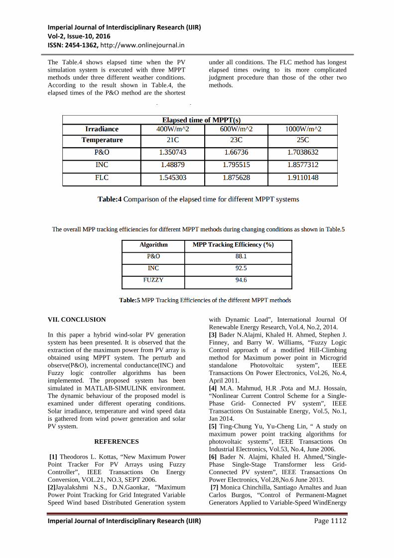
The Table.4 shows elapsed time when the PV simulation system is executed with three MPPT methods under three different weather conditions. According to the result shown in Table.4, the elapsed times of the P&O method are the shortest
under all conditions. The FLC method has longest elapsed times owing to its more complicated judgment procedure than those of the other two methods.
VII. CONCLUSION In this paper a hybrid wind-solar PV generation system has been presented. It is observed that the extraction of the maximum power from PV array is obtained using MPPT system. The perturb and observe(P&O), incremental conductance(INC) and Fuzzy logic controller algorithms has been implemented. The proposed system has been simulated in MATLAB-SIMULINK environment. The dynamic behaviour of the proposed model is examined under different operating conditions. Solar irradiance, temperature and wind speed data is gathered from wind power generation and solar PV system.
REFERENCES
[1] Theodoros L. Kottas, “New Maximum Power Point Tracker For PV Arrays using Fuzzy Controller”, IEEE Transactions On Energy Conversion, VOL.21, NO.3, SEPT 2006. [2]Jayalakshmi N.S., D.N.Gaonkar, ”Maximum Power Point Tracking for Grid Integrated Variable Speed Wind based Distributed Generation system
with Dynamic Load”, International Journal Of Renewable Energy Research, Vol.4, No.2, 2014. [3] Bader N.Alajmi, Khaled H. Ahmed, Stephen J. Finney, and Barry W. Williams, “Fuzzy Logic Control approach of a modified Hill-Climbing method for Maximum power point in Microgrid standalone Photovoltaic system”, IEEE Transactions On Power Electronics, Vol.26, No.4, April 2011. [4] M.A. Mahmud, H.R .Pota and M.J. Hossain, “Nonlinear Current Control Scheme for a Single-Phase Grid- Connected PV system”, IEEE Transactions On Sustainable Energy, Vol.5, No.1, Jan 2014. [5] Ting-Chung Yu, Yu-Cheng Lin, “ A study on maximum power point tracking algorithms for photovoltaic systems”, IEEE Transactions On Industrial Electronics, Vol.53, No.4, June 2006. [6] Bader N. Alajmi, Khaled H. Ahmed,”Single-Phase Single-Stage Transformer less Grid-Connected PV system”, IEEE Transactions On Power Electronics, Vol.28,No.6 June 2013. [7] Monica Chinchilla, Santiago Arnaltes and Juan Carlos Burgos, “Control of Permanent-Magnet Generators Applied to Variable-Speed WindEnergy

Imperial Journal of Interdisciplinary Research (IJIR) Vol-2, Issue-10, 2016 ISSN: 2454-1362, http://www.onlinejournal.in
Imperial Journal of Interdisciplinary Research (IJIR) Page 1113
Systems Connected to the Grid” IEEE Transactions On Energy Conversion, Vol 21, NO, 1, March 2006 Pp. 130-135. [8] C.Y Won, D.H. kim, W.S. Kim, ” A new maximum power point tracker of PV arrays using Fuzzy Logic Controller”, IEEE 25th Annu. Power Electron. Spec. Conf., 1994, vol.1, pp. 396-403. [9] Ashish Pandey, Nivedita Dasgupta,”High-Performance Alogorithms for Drift Avoidance and
Fast Tracking in Solar MPPT System”, IEEE Transaactions On Energy Conversion, Vol.23, No.2, June 2008. [10] Fangrui Liu, Shanxu Duan,” A Variable Step Size Inc Mppt Method For Pv Systems”, IEEE Transaactions On Industrial Electronics, Vol.55, No.7 July 2008.