imperceptible electrooculography graphene sensor system
TRANSCRIPT

ARTICLE OPEN
Imperceptible electrooculography graphene sensor system forhuman–robot interfaceShideh Kabiri Ameri1, Myungsoo Kim 1, Irene Agnes Kuang 2, Withanage K. Perera3, Mohammed Alshiekh 3, Hyoyoung Jeong1,Ufuk Topcu3, Deji Akinwande1,4 and Nanshu Lu 1,2,3,4
Electrooculography (EOG) is a method to record the electrical potential between the cornea and the retina of human eyes. Despitemany applications of EOG in both research and medical diagnosis for many decades, state-of-the-art EOG sensors are still bulky,stiff, and uncomfortable to wear. Since EOG has to be measured around the eye, a prominent area for appearance with delicateskin, mechanically and optically imperceptible EOG sensors are highly desirable. Here, we report an imperceptible EOG sensorsystem based on noninvasive graphene electronic tattoos (GET), which are ultrathin, ultrasoft, transparent, and breathable. The GETEOG sensors can be easily laminated around the eyes without using any adhesives and they impose no constraint on blinking orfacial expressions. High-precision EOG with an angular resolution of 4° of eye movement can be recorded by the GET EOG and eyemovement can be accurately interpreted. Imperceptible GET EOG sensors have been successfully applied for human–robotinterface (HRI). To demonstrate the functionality of GET EOG sensors for HRI, we connected GET EOG sensors to a wirelesstransmitter attached to the collar such that we can use eyeball movements to wirelessly control a quadcopter in real time.
npj 2D Materials and Applications (2018) 2:19 ; doi:10.1038/s41699-018-0064-4
INTRODUCTIONWearable electronics have found many applications in fitnesstracking, mobile health monitoring, medical diagnosis,human–machine interfaces (HMIs), assistive technology, internetof things (IoT), etc.1–8 Nevertheless, despite the growing needs,developing wearable devices that offer both functionality andwearability has remained a major challenge. In recent years,stretchable thin-film electronics and wearables, including epider-mal sensors or electronic tattoos (e-tattoos), have achievedmechanical properties similar to human skin and demonstrateda wide range of functionalities, including physiological sensing,9–14 on-skin display,15 UV detection,16 transdermal therapeutics,17
HMIs,4,18 and prosthetic electronic skin.19 Compared with conven-tional wearable devices, a unique advantage of e-tattoos is theirthinness and softness, which enables noninvasive but intimatecoupling with microscopically rough human skin.20,21 Suchconformability is confirmed to be responsible for the highsignal-to-noise ratio (SNR) and low-motion artifacts of e-tattoosensors.4,22,23 Although the concept of imperceptible electronicshas been introduced for ultra-lightweight plastic electronics,24,25
none of them are optically transparent, which limits theirwearability on areas of esthetic prominence such as the humanface.The development of optically transparent e-tattoos requires
transparent conductive thin films26,27 such as 2D atomic sheets,28
nanocrystals-based composites,29,30 and intrinsically conductivetransparent polymers.31 However, transparent conductive materi-als for wearable e-tattoos have to meet some additional criteria.For skin integration, these materials must be biocompatible andelectrochemically inert. Furthermore, the thickness of conductors
should be scalable to microns or even sub-microns to ensureconformability to skin.9,32 As a result, graphene and MoS2nanomaterials are of significant relevance for e-tattoos due totheir atomic thinness, optical transparency, electrochemicalinertness, and biocompatibility.33–38 Recently, graphene-basedwearable strain gauge, temperature sensor, heater, and inter-connects have been reported.39,40 However, the combinedthickness of the patch is few micrometers39 or hundreds ofmicrometers,40 which is too thick to fully conform to themicromorphology of human skin according to theoretical analysisand experimental validation.32 Monolayer graphene-based kir-igami for stretchable electronics has been realized by otherresearcher. However, the application of such devices for on-skinelectrophysiological measurements could be challenging sincesuch devices need to be suspended in liquid or air to have 3Ddeformability. Furthermore, the use of laser beam to unfold andrefold such structure is not realistic in living systems.41 BilayerMoS2-based strain gauge and pressure sensor with grapheneinterconnects has been demonstrated with thickness below75 nm.42 However, this device is flexible but not stretchable andit only measures mechanical strain. Also it is important to noticethat since sub-micrometer-thick e-tattoos are difficult to reuse,low-cost, rapid prototyping and manufacturing process is desir-able. The micro-transfer printing technology43 applied to fabricatethe 2D materials-based skin patches39,40 is known to be cost andlabor intensive owing to photolithography, chemical etching, andmeticulous integration processes. To overcome such limitations,we recently developed a “wet transfer, dry patterning” method,which enable time and cost-effective freeform fabrication of 500-nm-thick graphene electronic tattoo (GET) sensors out of
Received: 30 October 2017 Revised: 24 May 2018 Accepted: 31 May 2018
1Department of Electrical and Computer Engineering, University of Texas at Austin, Austin, TX, USA; 2Department of Biomedical Engineering, University of Texas at Austin, Austin,TX, USA; 3Department of Aerospace Engineering and Engineering Mechanics, University of Texas at Austin, Austin, TX, USA and 4Texas Materials Institute, University of Texas atAustin, Austin, TX, USACorrespondence: Deji Akinwande ([email protected]) or Nanshu Lu ([email protected])
www.nature.com/npj2dmaterials
Published in partnership with FCT NOVA with the support of E-MRS
graphene/polymer bilayer.44 GET sensors were successfullyapplied for electrophysiology, skin hydration, and skin tempera-ture measurements.44 However, since the previous GET sensorsdoes not consist of any encapsulation over graphene, wherever ittouches the skin, the average signal will be picked up. This induceslimitation in application of GET for EOG in which the non-localizedmeasurement is not desirable. We therefore have to modify the“wet transfer, dry patterning” process to achieve GET EOG sensors.EOG has various applications including brain and sleep studies,
assistive technology, sleep and mental disorder diagnosis, andHMIs.45–49 EOG along with electroencephalogram (EEG) andelectromyogram (EMG) are used for patients suffering from neuralsystem disorders such as progressive neuro-motor degenerativediseases. However, compared with EEG and EMG, EOG has twomajor advantages. First, analysis of the EOG signals is less complexbecause the relationship between EOG and eye movement islinear within a certain range, and the waveform is easy to detect.Second, EOG signal is more stable.50,51 Conventionally, silver/silverchloride (Ag/AgCl) gel electrodes are used for EOG measurementand even currently, most EOG measurements are measured usingcommercially available dry or wet silver/silver chloride electro-des.45,49,52–54 For example, Ubeda et al. measured EOG using drysilver–silver chloride electrodes and used the signal for controllinga robotic arm.55 In other works, EOG sensors were mounted ongoggles for wearability.47,56–58 Vehkaoja et al. engineered silver-coated fibers as flexible EOG sensors, but they should bemoisturized with conductive saline solution to enable recording.59
Although these electrodes are readily available and affordable,they are thick, stiff, uncomfortable to delicate eye skin, andnoticeable on face. Wet electrodes are known for lowelectrode–skin interface impedance and low susceptibility tomotion but gels are irritating to skin and dry out by time resulting
in degrading the quality of the recorded signal. Dry electrodes arebetter option for long-term measurements but they suffer fromhigh electrode–skin interface impedance due to non-conformablecontact to skin and they are susceptible to motion artifact.60
Ultrathin and stretchable tattoo-like EOG sensors based onfilamentary serpentine gold ribbons on polymer substrate havebeen reported.22 But gold-based electrodes and interconnects arevery noticeable on prominent area such as human face. In otherreported work, EOG sensor combined with other sensors andcircuit components were integrated in a patch with the thicknessof several millimeter.61 Such a patch is not only obvious, but alsoobstructive to facial expression. The GET EOG sensor systempresented here has a thickness of 350 nm, optical transparency of85% in the visible regime (wavelength from 400 to 800 nm), andstretchability up to 50%, which is truly mechanically and opticallyimperceptible EOG sensor. We found that the GET EOG sensors arecapable of detecting eye movement with a resolution of about 4°.Connecting the imperceptible GET EOG sensors to an OpenBCICyton board capable of wireless communication, we demonstratereal-time wireless quadcopter control through eye movements.
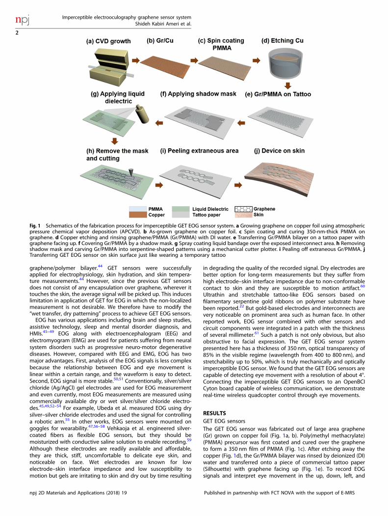
RESULTSGET EOG sensorsThe GET EOG sensor was fabricated out of large area graphene(Gr) grown on copper foil (Fig. 1a, b). Poly(methyl methacrylate)(PMMA) precursor was first coated and cured over the grapheneto form a 350 nm film of PMMA (Fig. 1c). After etching away thecopper (Fig. 1d), the Gr/PMMA bilayer was rinsed by deionized (DI)water and transferred onto a piece of commercial tattoo paper(Silhouette) with graphene facing up (Fig. 1e). To record EOGsignals and interpret eye movement in the up, down, left, and
Fig. 1 Schematics of the fabrication process for imperceptible GET EOG sensor system. a Growing graphene on copper foil using atmosphericpressure chemical vapor deposition (APCVD). b As-grown graphene on copper foil. c Spin coating and curing 350-nm-thick PMMA ongraphene. d Copper etching and rinsing graphene/PMMA (Gr/PMMA) with DI water. e Transferring Gr/PMMA bilayer on a tattoo paper withgraphene facing up. f Covering Gr/PMMA by a shadow mask. g Spray coating liquid bandage over the exposed interconnect area. h Removingshadow mask and carving Gr/PMMA into serpentine-shaped patterns using a mechanical cutter plotter. i Pealing off extraneous Gr/PMMA. jTransferring GET EOG sensor on skin surface just like wearing a temporary tattoo
Imperceptible electrooculography graphene sensor systemShideh Kabiri Ameri et al.
2
npj 2D Materials and Applications (2018) 19 Published in partnership with FCT NOVA with the support of E-MRS
1234567890():,;
right directions, a minimum of four EOG sensors are neededaround the eyes. Each GET EOG sensor consists of three parts, (1) adisk-shaped electrode where graphene is exposed to make directcontact with the skin to capture the EOG signals, (2) an exposedrectangular graphene terminal pad to connect to flexible goldconnector, and (3) an encapsulated serpentine-shaped intercon-nect linking parts (1) and (2). To encapsulate the serpentineinterconnects, we applied a shadow mask made by a desktopmechanical cutter plotter (Silhouette) to cover the electrode andthe terminal pad (Fig. 1f), followed by spray coating liquidbandage (Nexcare) to cover the exposed interconnects (Fig. 1g).Within 10–15 s, the liquid bandage solidified into an insulatingpolymeric layer of roughly 2 µm thickness (Fig. S2). Encapsulatinginterconnects allow for localized EOG measurement from theexposed disk-shaped electrodes right next to the eyes. After theencapsulation, we removed the shadow mask and used the samemechanical cutter plotter (Silhouette) to carve Gr/PMMA with pre-designed patterns (Fig. 1h). To show the necessity of encapsula-tion layer on interconnect for localized EOG measurements, weplaced two electrodes on the top of an eyebrow of a humansubject. One was placed vertically above an eyebrow (location B inFig. S1a) and the other one at the inclined top, where GETinterconnect normally passes through (location A in Fig. S1a).These electrodes work as two separate positive terminals of twochannels of our recording system. We then placed anotherelectrode at the bottom of the same eye (Fig. S1a), which acts as ashared electrode connected to the negative terminal of bothchannels. Then, we measured EOG signals simultaneously usingboth channels during eyes moving up and down. If EOG signal isnaturally localized, there should be no recorded signal using theelectrode placed in location A. However, clearly there is thenonzero EOG signal measured at location A as it is shown in Fig.S1b. The EOG recorded at location A is in phase with but hassmaller amplitude than that measured at location B. Therefore,covering interconnects with encapsulation layer is necessary forlocalized EOG measurements. The GET EOG sensors weredesigned in the serpentine-shaped ribbons to enable stretch-ability. The stretchability of the GET was measured in our previousto be about 50%.44 In the last step of EOG GET fabrication,extraneous Gr/PMMA was carefully peeled off, leaving GET EOGsensors on the tattoo paper (Fig. 1i). A layer of water-solubleadhesive comes with the tattoo paper can facilitate the release ofGET EOG. To laminate GET EOG around the eyes, the tattoo paperwas placed on skin with GET EOG facing the skin, followed by
wetting the backside of the tattoo paper and then carefullypeeling the paper off the skin, leaving open-mesh GET EOGsensors on the skin (Fig. 1j and Supplementary Video VS1).The GET EOG sensors formed steady contact with human skin
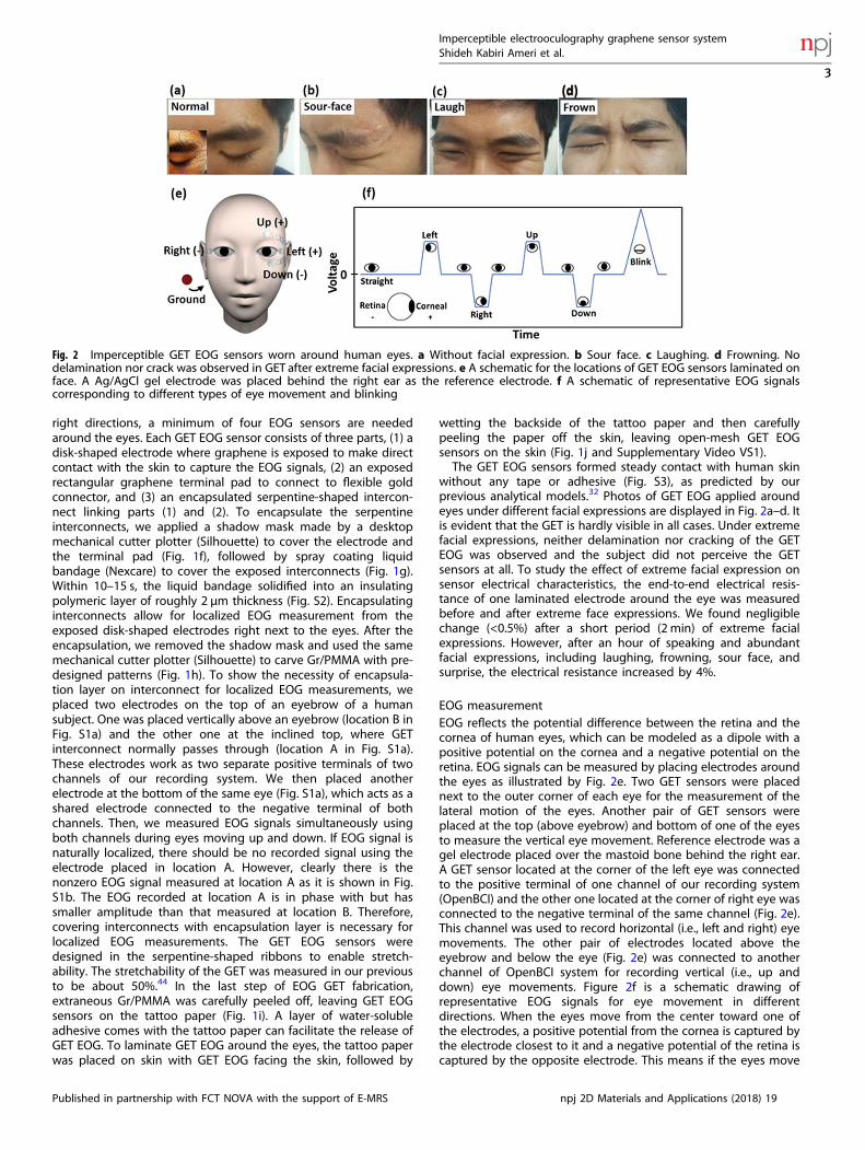
without any tape or adhesive (Fig. S3), as predicted by ourprevious analytical models.32 Photos of GET EOG applied aroundeyes under different facial expressions are displayed in Fig. 2a–d. Itis evident that the GET is hardly visible in all cases. Under extremefacial expressions, neither delamination nor cracking of the GETEOG was observed and the subject did not perceive the GETsensors at all. To study the effect of extreme facial expression onsensor electrical characteristics, the end-to-end electrical resis-tance of one laminated electrode around the eye was measuredbefore and after extreme face expressions. We found negligiblechange (<0.5%) after a short period (2 min) of extreme facialexpressions. However, after an hour of speaking and abundantfacial expressions, including laughing, frowning, sour face, andsurprise, the electrical resistance increased by 4%.
EOG measurementEOG reflects the potential difference between the retina and thecornea of human eyes, which can be modeled as a dipole with apositive potential on the cornea and a negative potential on theretina. EOG signals can be measured by placing electrodes aroundthe eyes as illustrated by Fig. 2e. Two GET sensors were placednext to the outer corner of each eye for the measurement of thelateral motion of the eyes. Another pair of GET sensors wereplaced at the top (above eyebrow) and bottom of one of the eyesto measure the vertical eye movement. Reference electrode was agel electrode placed over the mastoid bone behind the right ear.A GET sensor located at the corner of the left eye was connectedto the positive terminal of one channel of our recording system(OpenBCI) and the other one located at the corner of right eye wasconnected to the negative terminal of the same channel (Fig. 2e).This channel was used to record horizontal (i.e., left and right) eyemovements. The other pair of electrodes located above theeyebrow and below the eye (Fig. 2e) was connected to anotherchannel of OpenBCI system for recording vertical (i.e., up anddown) eye movements. Figure 2f is a schematic drawing ofrepresentative EOG signals for eye movement in differentdirections. When the eyes move from the center toward one ofthe electrodes, a positive potential from the cornea is captured bythe electrode closest to it and a negative potential of the retina iscaptured by the opposite electrode. This means if the eyes move
Fig. 2 Imperceptible GET EOG sensors worn around human eyes. a Without facial expression. b Sour face. c Laughing. d Frowning. Nodelamination nor crack was observed in GET after extreme facial expressions. e A schematic for the locations of GET EOG sensors laminated onface. A Ag/AgCl gel electrode was placed behind the right ear as the reference electrode. f A schematic of representative EOG signalscorresponding to different types of eye movement and blinking
Imperceptible electrooculography graphene sensor systemShideh Kabiri Ameri et al.
3
Published in partnership with FCT NOVA with the support of E-MRS npj 2D Materials and Applications (2018) 19

to the left, the pair of horizontal electrodes would be able tocapture a positive potential, and a negative potential appears bymoving the eyes toward the right. Eyes moving upward producesa positive potential and looking downward results in a negativepotential; blinks would be recorded as sharp positive peaks. Theamplitude of EOG signals varies from case to case and is reportedto be between 5 and 20 µV per degree of eye movement and inthe low-frequency range up to 30 Hz.56 The cause of the blinksignal is different from the EOG signal. EOG originates frompotential difference between retina and cornea but blinks are dueto activity of the levator palpe-brae superioris and the orbicularisoculi muscles located around the eyes. Blinks that start with uppereyelid moving downward followed by the orbicularis oculi muscleactivity has the duration of 300–550ms.52,62
To acquire EOG, GET sensors were connected to an OpenBCICyton Biosensing board, which can perform data acquisition(DAQ) at a sampling rate of 250 Hz and then wirelessly transfersEOG data to a laptop for signal processing and quadcoptercontrol. Figure 3a shows a schematic of the complete HRI system.Flexible gold/polyethylene terephthalate (Au/PET) ribbons werefabricated by mechanically cutting and patterning commerciallyavailable Au/PET sheets (Rotex Tech.) to connect GET EOG sensorsto thin lead wires fed into the OpenBCI (Figs. S4a–S4e). To reducemechanical motion, the lead wires were fixed around ears usingtwo earbud hooks (Fig. S4f). Figure 3b–d shows pictures of thewireless EOG sensor system worn by a subject. To guide the eyemovement, we placed a signaling board with five individuallycontrollable light-emitting diodes (LEDs) in front of the subject(Fig. S5). The distance from the board was adjusted to provide 45°of eyeball movement from center toward every direction (up,down, left, and right). To measure the EOG of a specific eyemovement, the subject was asked to move his eyes toward theonly LED that was on at a given time. The EOG signals recorded byGET EOG sensors during eye movement are shown in Fig. 3e, f.The amplitude of EOG signal recorded using GET was 17.7 ± 1.5 µVper degree in the horizontal direction and 12.8 ± 0.5 µV in thevertical direction, which are consistent with those reported in
literature.56 We have observed clear voltage steps for successiveeye movement of 4° in both horizontal and vertical directions asshown in supplementary Fig. S6.
Human–robot interface demonstrationThe EOG signal during eye movement was utilized forhuman–robot interface. The flowchart of MATLAB coding usedfor EOG signal processing and classification of EOG signals forquadcopter control is shown in Fig. 4a. Prior to classification,baseline drift removal and data averaging were implemented. Thebaseline drift removal process involves averaging a slidingwindow of 250 samples to predict the drift, then removing thataverage value from the next data point of the window.63 Tosmooth out the signal, every ten samples were averaged. Risesand falls in the electric potential representing the right/left andup/down movement of the eyes can then be easily detected. Fiveseparate thresholds were used in order to discretely detect blink(500 µV), right (400 µV), left (−400 µV), up (400 µV), and down(−400 µV) movement. The blink signals with amplitude higherthan 500 µV were registered as Stay command. EOG signals due toup, down, left, and right eye movement were registered ascommands to be sent to the quadcopter (Qualcomm Snapdragon)if their magnitudes were between 400 and 500 µV. During real-time quadcopter control, the maximum angle of eye movementsin the vertical direction was about 70° and in the horizontaldirection about 50°, as convenient for the human subject. Theclassification was performed by first computing the number ofsamples passing each unique threshold. The threshold met mostfrequently was given a unique label corresponding to thatthreshold. The label that occurred most often in a set of 1000labels was chosen and transmitted to the robot-operating system(ROS). The label was converted to a command, and the commandprompts the corresponding change in the position of thequadcopter. Figure 4b–f displays photos of a subject controllinga quadcopter by looking up, down, left, and right. The quadcopterfollowed the eye movement to fly up, down, left, and right. The
Fig. 3 Illustrations of GET EOG system worn by a subject and actual EOG signals recorded by GET EOG sensors. a A schematic of the GET EOGsensors connected to an OpenBCI board, which performs DAQ and wirelessly transmits EOG data to the laptop. The laptop performs dataclassification and wirelessly sends commands to the quadcopter. Photos of b front view, c side view and, d back view of the GET EOG sensorsystem worn on a subject. EOG signals recorded by GET sensors during the following repeated eye movement: e looking straight, right, andleft each for few seconds, f looking straight, down, and up each for few seconds, g repeated intentional blinks
Imperceptible electrooculography graphene sensor systemShideh Kabiri Ameri et al.
4
npj 2D Materials and Applications (2018) 19 Published in partnership with FCT NOVA with the support of E-MRS

flying distance of the quadcopter was pre-set in the ROS to beindependent from the angle of eye movements. We only used theEOG signal to control the direction of the flight. SupplementaryVideo VS2 offers a real-time example of how the GET EOG sensor isused for HRI. We found the accuracy of our classifier to be 92 ± 2%.
DISCUSSIONThe results presented here is the proof of concept for ultrathin,ultrasoft, imperceptible GET sensors for recording EOG from theface and their potential application in HRI. The wearability of theGET sensor is considerably higher, and the manufacturing cost issignificantly lower than existing e-tattoos with similar function-ality. The primary consequence of the low thickness of GET is the
conformal contact with skin texture and as a result, the improvedSNR and decreased susceptibility to motion. Our previous workreported that the SNR of the signal measured recorded by the GET(15.22 dB) is slightly higher than the SNR of the signal recorded bycommercial gel electrodes (11 dB).44 Flexible connectors and DAQsystems used in this work could be further improved. For example,using transparent conductive materials instead of gold/PET as theflexible connectors can further reduce the visibility of the system.Replacing commercially available OpenBCI board with customized,miniature-printed circuit board (PCB) that can directly commu-nicate with the quadcopter will make the system even moremobile. Other 2D materials can potentially be integrated into thecurrent GET platform for multimodal sensing, and on-tattoo signalamplification/processing.
Fig. 4 Flowchart of the human–robot interface (HRI) used to control the quadcopter via eyeball movement. The EOG signals captured bysensors are sampled and transmitted to a laptop by the OpenBCI board. The raw data are first averaged and then passed onto the thresholddetector to determine the eyeball movement direction and issues a command accordingly. From the command and the current locationobtained from the motion capture system, the path planner calculates and sends a sequence of waypoints that the quadcopter needs tofollow to the on-board position controller, which in turn sends attitude commands to the attitude controller (both controllers are part of thePX4 stack). The attitude controller then tilts the quadcopter so that it moves to the target waypoint which is then detected by Vicon motioncapture system movement. b Quadcopter stayed stationary if subject did not move his eyes or if he blinked, c flew upward by looking up, ddown by looking down, e right by looking toward the right and, f left by looking to the left. The insets in Fig. 4b to 4f show magnified photosof the human subjects eyes looking in different directions to control the flying of the quadcopter.
Imperceptible electrooculography graphene sensor systemShideh Kabiri Ameri et al.
5
Published in partnership with FCT NOVA with the support of E-MRS npj 2D Materials and Applications (2018) 19

METHODSGraphene growth and fabrication: Graphene was grown using atmosphericpressure chemical vapor deposition system (APCVD) on copper foil (OAK-MITSUI, 99.4%). The growth was done at ~1030 °C by flowing hydrogen at10 sccm for 15min, followed by flowing methane at 2 sccm and argon with300 sccm for 10min. Poly(methyl methacrylate) (PMMA 950 A4, MICRO-CHEM) was spin-coated on the graphene at 3000 rpm and cured at 180 °Cfor 2 min. After etching the copper using copper etchant (TranseneCompany INC.), Gr/PMMA was transferred on Silhouette tattoo paper.Using shadow mask, some area of Gr/PMMA was covered and then aNexcard liquid bandage was sprayed on graphene (interconnect wereformed from the area of graphene covered with liquid bandage). Afterliquid bandage was dried out shadow masks were removed. Then EOG GETwas cut out of Gr/PMMA using Silhouette Cameo mechanical cutter plotterinto pre-designed stretchable patterns. The extraneous area was thenpeeled off manually, leaving GET EOG sensor on the tattoo paper.All experiments were conducted under approval from the Institutional
Review Board at the University of Texas at Austin (protocol number: 2015-05-0024)
Data availabilityAll relevant data are available upon request.Data acquisition system: OpenBCI’s Cyton Biosensing Board consists of
an 8-channel neural interface, a 32 bit-processor, and a Bluetooth(RFduino) module. The board houses a PIC32MX250F128B microcontrollerat the core, and the ADS1299 24-bit analog-to-digital converter with eightdifferential input channels. OpenBCI Cyton is actually one Python node in alarger collection of Python nodes, which work together in an ROS-basedsystem.
ACKNOWLEDGEMENTSThis work is supported by the US National Science Foundation (NSF) under Grant Nos.ECCS-1541684 and CNS-1738293. N.L. is very thankful to the support from the YoungInvestigator Program (YIP) of Office of Naval Research (ONR) under Grant No. N00014-16-1-2044. D.A. acknowledges the support of David & Doris Lybarger EndowedFaculty Fellowship and ONR.
AUTHOR CONTRIBUTIONSS.K.A. designed and fabricated the EOG sensor and system, the EOG recording andHRI experiments, and contributed in data processing. M.K. and I.K. contributed infabricating devices, I.K. contributed in signal processing and performing EOGrecording. W.P. and M.A. contributed in the writing codes for HRI and ROS. H.J.contributed in HRI experiment. U.T. supervised HRI experiment and N. L. and D.A.supervised the research.
ADDITIONAL INFORMATIONSupplementary information accompanies the paper on the npj 2D Materials andApplications website (https://doi.org/10.1038/s41699-018-0064-4).
Competing interests: The authors declare no competing interests.
Publisher's note: Springer Nature remains neutral with regard to jurisdictional claimsin published maps and institutional affiliations.
REFERENCES1. Bareket, L. et al. Temporary-tattoo for long-term high fidelity biopotential
recordings. Sci. Rep. 6, 25727 (2016).2. Huang, X., Yeo, W. H., Liu, Y. & Rogers, J. A. Epidermal differential impedance
sensor for conformal skin hydration monitoring. Biointerphases 7, 52 (2012).3. Kenry, Yeo, J. C. & Lim, C. T. Emerging flexible and wearable physical sensing
platforms for healthcare and biomedical applications. Microsyst. Nanoeng. 2,16043 (2016).
4. Jeong, J. W. et al. Materials and optimized designs for human-machine interfacesvia epidermal electronics. Adv. Mater. 25, 6839–6846 (2013).
5. Gao, W. et al. Fully integrated wearable sensor arrays for multiplexed in situperspiration analysis. Nature 529, 509–514 (2016).
6. Nyein, H. Y. et al. A wearable electrochemical platform for noninvasive simulta-neous monitoring of Ca(2+) and pH. ACS Nano 10, 7216–7224 (2016).
7. Metcalf, D., Milliard, S. T., Gomez, M. & Schwartz, M. Wearables and the internet ofthings for health: wearable, interconnected devices promise more efficient andcomprehensive health care. IEEE Pulse 7, 35–39 (2016).
8. Lo, B. P. L., Ip, H. & Yang, G. Z. Transforming health care: body sensor networks,wearables, and the internet of things. IEEE Pulse 7, 4–8 (2016).
9. Kim, D.-H. et al. Epidermal electronics. Science 333, 838–843 (2011).10. Bandodkar, A. J., Jia, W. & Wang, J. Tattoo-based wearable electrochemical
devices: a review. Electroanal 27, 11 (2015).11. Webb, R. C. B. et al. Ultrathin conformal devices for precise and continuous
thermal characterization of human skin. Nat. Mater. 12, 938–944 (2013).12. Kim, J. et al. Battery-free, stretchable optoelectronic systems for wireless optical
characterization of the skin. Sci. Adv. 2, e1600418 (2016).13. Jang, K. I. et al. Rugged and breathable forms of stretchable electronics with
adherent composite substrates for transcutaneous monitoring. Nat. Commun. 5,4779 (2014).
14. Xu, S. et al. Soft microfluidic assemblies of sensors, circuits, and radios for theskin. Science 344, 70–74 (2014).
15. Koo, J. H. et al. Wearable electrocardiogram monitor using carbon nanotubeelectronics and color-tunable organic light-emitting diodes. ACS Nano 11,10032–10041 (2017).
16. Araki, H. et al. Materials and device designs for an epidermal UV colorimetricdosimeter with near field communication capabilities. Adv. Funct. Mater. 27,1604465 (2017).
17. Son, D. et al. Multifunctional wearable devices for diagnosis and therapy ofmovement disorders. Nat. Nanotechnol. 9, 397–404 (2014).
18. Song, J.-K. et al. Wearable force touch sensor array using a flexible and trans-parent electrode. Adv. Funct. Mater. 27, 1605286 (2017).
19. Chortos, A., Liu, J. & Bao, Z. Pursuing prosthetic electronic skin. Nat. Mater. 15,937–950 (2016).
20. Wang, S. et al. Mechanics of epidermal electronics. J. Appl. Mech. 79, 031022(2012).
21. Wang, L. & Lu, N. Conformability of a thin elastic membrane laminated on a softsubstrate with slightly wavy surface. J. Appl. Mech. 83, 041007 (2016).
22. Jeong, J. W. et al. Capacitive epidermal electronics for electrically safe, long-termelectrophysiological measurements. Adv. Healthc. Mater. 3, 642–648 (2014).
23. Wang, Y. et al. Low-cost, μm-thick, tape-free electronic tattoo sensorswith minimized motion and sweatartifacts. NPJ Flexible Electronics 6, 1–6(2018).
24. Kaltenbrunner, M. et al. An ultra-lightweight design for imperceptible plasticelectronics. Nature 499, 458–463 (2013).
25. Melzer, M. et al. Imperceptible magnetoelectronics. Nat. Commun. 6, 6080 (2015).26. Hecht, D. S., Hu, L. & Irvin, G. Emerging transparent electrodes based on thin films
of carbon nanotubes, graphene, and metallic nanostructures. Adv. Mater. 23,1482–1513 (2011).
27. Ellmer, K. Past achievements and future challenges in the development ofoptically transparent electrodes. Nat. Photonics 6, 809 (2012).
28. Akinwande, D. et al. A review on mechanics and mechanical properties of 2Dmaterials—graphene and beyond. Extrem. Mech. Lett. 13, 42–77 (2017).
29. Xue, J. et al. Nanowire-based transparent conductors for flexible electronics andoptoelectronics. Sci. Bull. 62, 143–156 (2017).
30. Song, J. & Zeng, H. Transparent electrodes printed with nanocrystal inks forflexible smart devices. Angew. Chem. 54, 9760–9774 (2015).
31. Wang, Y. et al. A highly stretchable, transparent, and conductive polymer. Sci.Adv. 3, e1602076 (2017).
32. Wang, L., Qiao, S., Ameri, S. K., Jeong, H. & Lu, N. A thin elastic membraneconformed to a soft and rough substrate subjected to stretching/compression. J.Appl. Mech. 84, 111003 (2017).
33. Shah, P., Narayanan, T. N., Li, C. Z. & Alwarappan, S. Probing the biocompatibilityof MoS2 nanosheets by cytotoxicity assay and electrical impedance spectroscopy.Nanotechnology 26, 315102 (2015).
34. Song, I., Park, C. & Choi, H. C. Synthesis and properties of molybdenum dis-ulphide: from bulk to atomic layers. RSC Adv. 5, 7495–7514 (2015).
35. Ameri, S. K. et al. Three dimensional graphene scaffold for cardiac tissueengineering and in-situ electrical recording. IEEE EMBC 3, 4201–4203(2016).
36. Ameri, S. K., Singh, P. K. & Sonkusale, S. Utilization of graphene electrode intransparent microwell arrays for high throughput cell trapping and lysis. Biosens.Bioelectron. 61, 625–630 (2014).
37. Na, S. R. et al. Clean graphene interfaces by selective dry transfer for large areasilicon integration. Nanoscale 8, 7523–7533 (2016).
38. Pinto, A. M., Goncalves, I. C. & Magalhaes, F. D. Graphene-based materials bio-compatibility: a review. Colloids Surf. B Biointerfaces 111, 188–202 (2013).
39. Choi, M. K. et al. Thermally controlled, patterned graphene transfer printing fortransparent and wearable electronic/optoelectronic system. Adv. Funct. Mater. 25,7109–7118 (2015).
Imperceptible electrooculography graphene sensor systemShideh Kabiri Ameri et al.
6
npj 2D Materials and Applications (2018) 19 Published in partnership with FCT NOVA with the support of E-MRS

40. Lee, H. et al. A graphene-based electrochemical device with thermoresponsivemicroneedles for diabetes monitoring and therapy. Nat. Nanotechnol. 11,566–572 (2016).
41. Blees, M. K. et al. Graphene kirigami. Nature 524, 204–207 (2015).42. Park, M. et al. MoS2-based tactile sensor for electronic skin applications. Adv.
Mater. 28, 2556–2562 (2016).43. Meitl, M. A. et al. Transfer printing by kinetic control of adhesion to an elasto-
meric stamp. Nat. Mater. 5, 33–38 (2006).44. Ameri, S. K. et al. Graphene electronic tattoo sensors. ACS nano 11, 7634–7641
(2017).45. Boukadoum, A. M. & Ktonas, P. Y. EOG-based recording and automated detection
of sleep rapid eye movements: a critical review, and some recommendations.Psychophysiology 23, 598–611 (1986).
46. Ding, Q., Tong, K. & Li, G. Development of an EOG (electro-oculography) basedhuman-computer interface. Int. Conf. IEEE Eng. Med. Biol. 7, 6829–6831 (2005).
47. Nam, Y., Koo, B., Cichocki, A. & Choi, S. GOM-Face: GKP, EOG, and EMG-basedmultimodal interface with application to humanoid robot control. IEEE Trans. BioMed. Eng. 61, 453–462 (2014).
48. Rac-Lubashevsky, R., Slagter, H. A. & Kessler, Y. Tracking real-time changes inworking memory updating and gating with the event-based eye-blink rate. Sci.Rep. 7, 2547 (2017).
49. Lam, R. W., Beattie, C. W., Buchanan, A., Remick, R. A. & Zis, A. P. Low electro-oculographic ratios in patients with seasonal affective disorder. Am. J. Psychiatry148, 1526–1529 (1991).
50. Siddiqui, U. & Shaikh, A. N. An overview of “electrooculography”. Int. J. Adv. Res.Comput. Commun. Eng. 2, 3 (2013).
51. Dey, N. Classification and Clustering In Biomedical Signal Processing (IGI Global,Hershey, PA, 2016).
52. Bour, L., Visser, O. B., Aramideh, M. & Speelman, J. Origin of eye and eyelidmovements during blinking. Mov. Disord. 17, S30–S32 (2002).
53. Yamagishi, K., Hori, J. & Miyakawa, M. Development of EOG-based communica-tion system controlled by eight-directional eye movements. Int. Conf. IEEE Eng.Med. Biol. 1, 2574–2577 (2006).
54. Magosso, E., Ursino, M., Zaniboni, A., Provini, F. & Montagna, P. Visual andcomputer-based detection of slow eye movements in overnight and 24-h EOGrecordings. Clin. Neurophysiol. 118, 1122–1133 (2007).
55. Ubeda, A., Ianez, E. & Azorın, M. J. Wireless and portable EOG-based interface forassisting disabled people. IEEE/ASME Trans. Mechatron. 6, 4 (2011).
56. Bulling, A., Ward, J. A., Gellersen, H. & Troster, G. Eye movement analysis foractivity recognition using electrooculography. IEEE Trans. Pattern Anal. Mach.Intell. 33, 741–753 (2011).
57. Mélodie, J. T. V., Bulling, A. & Gellersen, H. Wearable eye tracking for mentalhealth monitoring. Comput. Commun. 35, 6 (2012).
58. Barea, R., Boquete, L., Rodriguez-Ascariz, J. M., Ortega, S. & Lopez, E. Sensorysystem for implementing a human-computer interface based on electro-oculography. Sensors 11, 310–328 (2011).
59. Vehkaoja, A. T. et al. Wireless head cap for EOG and facial EMG measurements.Int. Conf. IEEE Eng. Med. Biol. 6, 5865–5868 (2005).
60. Searle, A. & Kirkup, L. A direct comparison of wet, dry and insulating bioelectricrecording electrodes. Physiol. Meas. 21, 271–283 (2000).
61. Jang, K. I. et al. Self-assembled three dimensional network designs for softelectronics. Nat. Commun. 8, 15894 (2017).
62. Merino, M., Gomez, I. M. & Molina, A. J. Envelope filter sequence to delete blinksand overshoots. BioMed. Eng. 14, 48 (2015).
63. Baek, C., Goo, Y. & Seo, J.-M. Real-time baseline wander removal from electro-oculography using probabilistic baseline prediction. MBEC 45, 78–81 (2014).
Open Access This article is licensed under a Creative CommonsAttribution 4.0 International License, which permits use, sharing,
adaptation, distribution and reproduction in anymedium or format, as long as you giveappropriate credit to the original author(s) and the source, provide a link to the CreativeCommons license, and indicate if changes were made. The images or other third partymaterial in this article are included in the article’s Creative Commons license, unlessindicated otherwise in a credit line to the material. If material is not included in thearticle’s Creative Commons license and your intended use is not permitted by statutoryregulation or exceeds the permitted use, you will need to obtain permission directlyfrom the copyright holder. To view a copy of this license, visit http://creativecommons.org/licenses/by/4.0/.
© The Author(s) 2018
Imperceptible electrooculography graphene sensor systemShideh Kabiri Ameri et al.
7
Published in partnership with FCT NOVA with the support of E-MRS npj 2D Materials and Applications (2018) 19