impedance and loop antennas - lanka education and research...
TRANSCRIPT
Impedance and Loop Antennas
Ranga Rodrigo
University of Moratuwa
January 4, 2009
Ranga Rodrigo (University of Moratuwa) Impedance and Loop Antennas January 4, 2009 1 / 41

Summary of Last Week’s Lecture
Gain
Gain can be defined as
G =maximum radiation intensity
maximum radiation intensity from a ref-erence antenna with same power output
(1)
G0 =
maximum radiation intensity fromsubject antenna
radiation intensity from (lossless)isotropic source with same power input
(2)
Ranga Rodrigo (University of Moratuwa) Impedance and Loop Antennas January 4, 2009 2 / 41

Summary of Last Week’s Lecture
Gain
G = kD (3)
where k is the efficiency factor.
Ranga Rodrigo (University of Moratuwa) Impedance and Loop Antennas January 4, 2009 3 / 41

Summary of Last Week’s Lecture Efficiency
Efficiency
Efficiency =Pout
Pin=
Rrad
Rrad + Rloss. (4)
Ranga Rodrigo (University of Moratuwa) Impedance and Loop Antennas January 4, 2009 4 / 41
Summary of Last Week’s Lecture Antenna Aperture
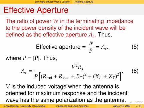
Effective ApertureThe ratio of power W in the terminating impedanceto the power density of the incident wave will bedefined as the effective aperture Ae. Thus,
Effective aperture =WP
= Ae, (5)
where P = |P|. Thus,
Ae =V2RT
P[(Rrad + Rloss + RT)2 + (XA + XT)2
] . (6)
V is the induced voltage when the antenna isoriented for maximum response and the incidentwave has the same polarization as the antenna.
Ranga Rodrigo (University of Moratuwa) Impedance and Loop Antennas January 4, 2009 5 / 41

Summary of Last Week’s Lecture Maximum Effective Aperture
Maximum Effective Aperture
XT = −XA (7)
RT = Rrad. (8)
W′ =V2RT
4R2T
=V2
4Rrad. (9)
Ranga Rodrigo (University of Moratuwa) Impedance and Loop Antennas January 4, 2009 6 / 41

Summary of Last Week’s Lecture Maximum Effective Aperture
The power W′ is delivered to the terminatingimpedance under the conditions of maximumpower transfer and zero antenna losses.The ration of this power to the power density ofthe incident wave is the maximum effectiveaperture Aem.
Maximum effective aperture =W′
P= Aem. (10)
Aem =V2
4PRrad. (11)
Ranga Rodrigo (University of Moratuwa) Impedance and Loop Antennas January 4, 2009 7 / 41

Summary of Last Week’s Lecture Maximum Effective Aperture of a Hertzian Dipole
Maximum Effective Aperture of aHertzian Dipole
Aem =120πE2(dl)2λ2
320π2E2(dl)2 =3λ2
8π= 0.119λ2. (12)
Ranga Rodrigo (University of Moratuwa) Impedance and Loop Antennas January 4, 2009 8 / 41

Summary of Last Week’s Lecture Maximum Effective Aperture of a Hertzian Dipole
Radiator Aem D D (dB)
Isotropicλ2
4π1 0
Short dipole1 3λ2
8π1.5 1.76
Half-wave dipole30λ2
73π1.64 2.14
1A short dipole is always of finite length even though it may be veryshort. The current along a short dipole is uniform.
Ranga Rodrigo (University of Moratuwa) Impedance and Loop Antennas January 4, 2009 9 / 41

Summary of Last Week’s Lecture Maximum Effective Aperture of a Hertzian Dipole
Received Power in a CommunicationSystem
Pr =PtAetAer
R2λ2 . (13)
Pr = PtGtGr
(λ
4πR
)2
. (14)
Ranga Rodrigo (University of Moratuwa) Impedance and Loop Antennas January 4, 2009 10 / 41

Self and Mutual Impedances
Self and Mutual Impedances:Introduction
The impedance presented by an antenna to atransmission line can be represented by a2-terminal network.The impedance into which the transmission lineoperates is called the terminal and driving-pointimpedance.If the antenna is isolated, i.e., remote fromground and other objects, and is lossless, itsterminal impedance is is the same as theself-impedance of the antenna.
Ranga Rodrigo (University of Moratuwa) Impedance and Loop Antennas January 4, 2009 11 / 41

Self and Mutual Impedances
Antenna
Transmission line
ZEquivalent impedance
Ranga Rodrigo (University of Moratuwa) Impedance and Loop Antennas January 4, 2009 12 / 41

Self and Mutual Impedances
Self-impedance
Self-resistance
Self-reactance
Ranga Rodrigo (University of Moratuwa) Impedance and Loop Antennas January 4, 2009 13 / 41

Self and Mutual Impedances
The self-impedance is the same for reception asfor transmission.In the case there are nearby objects, theterminal impedance can still be replaced by a2-terminal network. However, its value isdetermined not only by the self-impedance butalso by the mutual impedance by it and the otherantennas and the currents flowing on them.
Ranga Rodrigo (University of Moratuwa) Impedance and Loop Antennas January 4, 2009 14 / 41
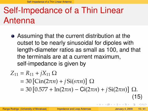
Self-Impedance of a Thin Linear Antenna
Self-Impedance of a Thin LinearAntenna
Assuming that the current distribution at theoutset to be nearly sinusoidal for dipoles withlength-diameter ratios as small as 100, and thatthe terminals are at a current maximum,self-impedance is given by
Z11 = R11 + jX11 Ω
= 30[Cin(2πn) + j Si(sπn)
]Ω
= 30[0.577 + ln(2πn) − Ci(2πn) + j Si(2πn)
]Ω.(15)
Ranga Rodrigo (University of Moratuwa) Impedance and Loop Antennas January 4, 2009 15 / 41

Self-Impedance of a Thin Linear Antenna
We will state what we mean by Cin, Ci, and Si now.They are three integrals. When we did the radiationresistance calculation, we avoided these integrals byusing the numerical result∫ π/2θ=0
cos2[(π/2) cosθ]sinθ dθ = 0.609.
Cin(x) =
∫ x
0
1 − cos(v)v
dv
= lnγx − Ci(x)= 0.577 + ln x − Ci(x).
(16)
where γ = ec = 1.781 or lnγ = c = 0.577 = Euler’sconstant.
Ranga Rodrigo (University of Moratuwa) Impedance and Loop Antennas January 4, 2009 16 / 41

Self-Impedance of a Thin Linear Antenna
Cosine IntegralThe part of this integral given by
Ci(x) = lnγx − Cin(x). (17)
is called the cosine integral. The value of thisintegral is given by
Ci(x) =
∫ x
∞
cos vv
= lnγx−x2
2!2+
x4
4!4−
x6
6!6+ · · · . (18)
When x is small (x < 0.2),
Ci(x) ' lnγx = 0.577 + ln x. (19)
When x is large (x 1),
Ci(x) =sin x
x. (20)Ranga Rodrigo (University of Moratuwa) Impedance and Loop Antennas January 4, 2009 17 / 41

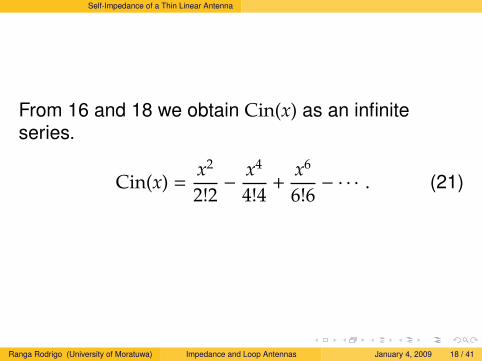
Self-Impedance of a Thin Linear Antenna
From 16 and 18 we obtain Cin(x) as an infiniteseries.
Cin(x) =x2
2!2−
x4
4!4+
x6
6!6− · · · . (21)
Ranga Rodrigo (University of Moratuwa) Impedance and Loop Antennas January 4, 2009 18 / 41
Self-Impedance of a Thin Linear Antenna
From 16 and 18 we obtain Cin(x) as an infiniteseries.
Cin(x) =x2
2!2−
x4
4!4+
x6
6!6− · · · . (21)
Ranga Rodrigo (University of Moratuwa) Impedance and Loop Antennas January 4, 2009 18 / 41

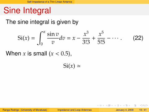
Self-Impedance of a Thin Linear Antenna
Sine IntegralThe sine integral is given by
Si(x) =
∫ x
0
sin vv
dv = x −x3
3!3+
x5
5!5− · · · . (22)
When x is small (x < 0.5),
Si(x) ' x. (23)
When x is large (x 1),
Si(x) 'π2−
cos xx. (24)
Ranga Rodrigo (University of Moratuwa) Impedance and Loop Antennas January 4, 2009 19 / 41
Self-Impedance of a Thin Linear Antenna
Sine IntegralThe sine integral is given by
Si(x) =
∫ x
0
sin vv
dv = x −x3
3!3+
x5
5!5− · · · . (22)
When x is small (x < 0.5),
Si(x) '
x. (23)
When x is large (x 1),
Si(x) 'π2−
cos xx. (24)
Ranga Rodrigo (University of Moratuwa) Impedance and Loop Antennas January 4, 2009 19 / 41

Self-Impedance of a Thin Linear Antenna
Sine IntegralThe sine integral is given by
Si(x) =
∫ x
0
sin vv
dv = x −x3
3!3+
x5
5!5− · · · . (22)
When x is small (x < 0.5),
Si(x) ' x. (23)
When x is large (x 1),
Si(x) 'π2−
cos xx. (24)
Ranga Rodrigo (University of Moratuwa) Impedance and Loop Antennas January 4, 2009 19 / 41

Self-Impedance of a Thin Linear Antenna
-1
-0.5
0
0.5
1
1.5
2
0 2 4 6 8 10
Ci(x)Si(x)
Figure 1: Cosine and Sine Integrals
Ranga Rodrigo (University of Moratuwa) Impedance and Loop Antennas January 4, 2009 20 / 41

Self-Impedance of a Thin Linear Antenna
Self-Resistance and Self-Reactance
Self-Resistance
R11 = 30 Cin(2πn) Ω
= 30 [0.577 + ln(2πn) − Ci(2πn)] Ω.(25)
Self-Reactance
X11 = 30 Si(2πn) Ω. (26)
Ranga Rodrigo (University of Moratuwa) Impedance and Loop Antennas January 4, 2009 21 / 41

Self-Impedance of a Thin Linear Antenna
Self-Resistance and Self-Reactance
Self-Resistance
R11 = 30 Cin(2πn) Ω
= 30 [0.577 + ln(2πn) − Ci(2πn)] Ω.(25)
Self-Reactance
X11 = 30 Si(2πn) Ω. (26)
Ranga Rodrigo (University of Moratuwa) Impedance and Loop Antennas January 4, 2009 21 / 41

Self-Impedance of a Thin Linear Antenna
These equations give the impedance values fora thin linear center-fed antenna that is an oddnumber (n) of λ/2.
ExampleFind the self-impedance of a λ/2 antenna.
Solution
The antenna is a λ/2 antenna. Therefore, n = 1. Wehave for the self-resistance and self-reactance
R11 = 30 Cin(2π), (27)
andX11 = 30 Si(2π). (28)
Ranga Rodrigo (University of Moratuwa) Impedance and Loop Antennas January 4, 2009 22 / 41

Self-Impedance of a Thin Linear Antenna
-1
-0.5
0
0.5
1
1.5
2
2.5
3
0 2 4 6 8 10
Ci(x)Si(x)
Cin(x)
Figure 2: Cin Integral
Ranga Rodrigo (University of Moratuwa) Impedance and Loop Antennas January 4, 2009 23 / 41

Self-Impedance of a Thin Linear Antenna
-1
-0.5
0
0.5
1
1.5
2
2.5
3
0 2 4 6 8 10
Ci(x)Si(x)
Cin(x)
2π
2.44
Figure 3: Cin Integral
Ranga Rodrigo (University of Moratuwa) Impedance and Loop Antennas January 4, 2009 24 / 41

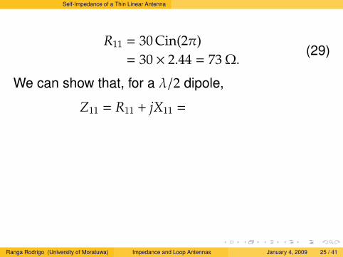
Self-Impedance of a Thin Linear Antenna
R11 = 30 Cin(2π)= 30 × 2.44 = 73 Ω.
(29)
We can show that, for a λ/2 dipole,
Z11 = R11 + jX11 = 73 + j42.5 Ω. (30)
Resonant “Half-Wave” DipoleSince X11 is not zero, an antenna exactly λ/2 long isnot resonant. To obtain a resonant antenna, it iscommon practice to shorten the antenna a fewpercent to make X11 = 0. In this case theself-resistance is somewhat less than 73 Ω.
Ranga Rodrigo (University of Moratuwa) Impedance and Loop Antennas January 4, 2009 25 / 41
Self-Impedance of a Thin Linear Antenna
R11 = 30 Cin(2π)= 30 × 2.44 = 73 Ω.
(29)
We can show that, for a λ/2 dipole,
Z11 = R11 + jX11 =
73 + j42.5 Ω. (30)
Resonant “Half-Wave” DipoleSince X11 is not zero, an antenna exactly λ/2 long isnot resonant. To obtain a resonant antenna, it iscommon practice to shorten the antenna a fewpercent to make X11 = 0. In this case theself-resistance is somewhat less than 73 Ω.
Ranga Rodrigo (University of Moratuwa) Impedance and Loop Antennas January 4, 2009 25 / 41

Self-Impedance of a Thin Linear Antenna
R11 = 30 Cin(2π)= 30 × 2.44 = 73 Ω.
(29)
We can show that, for a λ/2 dipole,
Z11 = R11 + jX11 = 73 + j42.5 Ω. (30)
Resonant “Half-Wave” DipoleSince X11 is not zero, an antenna exactly λ/2 long isnot resonant. To obtain a resonant antenna, it iscommon practice to shorten the antenna a fewpercent to make X11 = 0. In this case theself-resistance is somewhat less than 73 Ω.
Ranga Rodrigo (University of Moratuwa) Impedance and Loop Antennas January 4, 2009 25 / 41

Impedance at a Point Which is Not a Current Maximum
Impedance at a Point Which is Not aCurrent Maximum
When we use the methods above, what weobtain is the resistance and reactance at acurrent maximum.
This is not the point at which the transmissionline is connected for an antenna of generallength.
Ranga Rodrigo (University of Moratuwa) Impedance and Loop Antennas January 4, 2009 26 / 41

Impedance at a Point Which is Not a Current Maximum
Impedance at a Point Which is Not aCurrent Maximum
When we use the methods above, what weobtain is the resistance and reactance at acurrent maximum.This is not the point at which the transmissionline is connected for an antenna of generallength.
Ranga Rodrigo (University of Moratuwa) Impedance and Loop Antennas January 4, 2009 26 / 41

Impedance at a Point Which is Not a Current Maximum
Neglecting the antenna losses, the value ofradiation resistance so obtained is theresistance which would appear at the terminalsof a transmission line connected at a currentmaximum in the antenna, provided that theantenna current distribution on the antenna isthe same as when it is center-fed.
However, values can be transformed to thevalue which would appear across terminals ofthe transmission line connected at the center ofthe antenna.
Ranga Rodrigo (University of Moratuwa) Impedance and Loop Antennas January 4, 2009 27 / 41

Impedance at a Point Which is Not a Current Maximum
Neglecting the antenna losses, the value ofradiation resistance so obtained is theresistance which would appear at the terminalsof a transmission line connected at a currentmaximum in the antenna, provided that theantenna current distribution on the antenna isthe same as when it is center-fed.However, values can be transformed to thevalue which would appear across terminals ofthe transmission line connected at the center ofthe antenna.
Ranga Rodrigo (University of Moratuwa) Impedance and Loop Antennas January 4, 2009 27 / 41

Impedance at a Point Which is Not a Current Maximum
I0I1
x
A 3λ/4 dipole.
I=I0 cos βx. (31)
where
I1 = terminal current,I0 = maximum current.
This may be done byequating Prad = I2
0Rrad/2 tothe power supplied by thetransmission line I2
1R1/2,where I1 is the currentamplitude at the terminalsand R1 is the radiationresistance at this point.
I21
2R1 =
I20
2Rrad. (32)
Ranga Rodrigo (University of Moratuwa) Impedance and Loop Antennas January 4, 2009 28 / 41

Impedance at a Point Which is Not a Current Maximum
We can write
R1 =(I0
I1
)2
R0. (33)
Therefore,
R1 =Rrad
cos2 βx. (34)
The reactance X1 is given by
X1 =Xrad
sin2 βx. (35)
where Xrad is the reactance seen at a currentmaximum point.
Ranga Rodrigo (University of Moratuwa) Impedance and Loop Antennas January 4, 2009 29 / 41

Loop Antennas
Loop Antennas
Loop antennas are simple, inexpensive and veryversatile.They may be rectangular, circular, triangular orelliptical.Small loop antennas are defined as those withcircumference less thanλ/10 whereas largeloops are those with circumference on the orderof λ.They are mostly used in HF, VHF and UHFranges and are commonly used as probes atmicrowave frequencies.
Ranga Rodrigo (University of Moratuwa) Impedance and Loop Antennas January 4, 2009 30 / 41

Loop Antennas
Small Loop AntennasSmall loop antennas are usually used asreceivers rather than transmitters since they arevery compact, but not effective in transmittinglarge amount of power.Portable radios and pagers, where antennaefficiency is not very important as the signal tonoise ratio, utilize small loops as receivers.They are also used as probes for fieldmeasurement as well as for directional antennasin radio navigation.Reception can be increased by increasing theperimeter, the number of turns, or by inserting aferrite core (ferrite loop antenna).
Ranga Rodrigo (University of Moratuwa) Impedance and Loop Antennas January 4, 2009 31 / 41

Loop Antennas
The Small Loop AntennaThe field pattern of a small circular loop of radiusa may be determined very simply by consideringthe square loop of the same area, that is,
d2 = πa2 (36)
where d is the side length of square loop.It is assumed that the loop dimensions are smallcompare to the wavelenght.The far-field patterns of circular and squareloops of the same area are the same when theloops are small but different when they are largein terms of the wavelenght.
Ranga Rodrigo (University of Moratuwa) Impedance and Loop Antennas January 4, 2009 32 / 41

Loop Antennas
2a d
Figure 4: Circular and Square Loops of Equal Area.
Ranga Rodrigo (University of Moratuwa) Impedance and Loop Antennas January 4, 2009 33 / 41
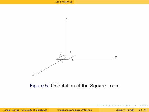
Loop Antennas
z
y
x
12
34
Figure 5: Orientation of the Square Loop.
Ranga Rodrigo (University of Moratuwa) Impedance and Loop Antennas January 4, 2009 34 / 41

Loop Antennas
z
y
θ
To distant point
d
Figure 6: Construction for Finding the Far Field of Dipoles 2and 4 of Square Loop.
Ranga Rodrigo (University of Moratuwa) Impedance and Loop Antennas January 4, 2009 35 / 41

Loop Antennas
If the loop is oriented with its plane lying in the xyplane, its far electric field has only an Eφ component.To find the far-field pattern in xy plane, it is onlynecessary to consider two of the four small lineardipoles (2 and 4). Since the individual small dipoles2 and 4 are nondirectional in the yz plane the fieldpattern of the loop in this plane is the same as thatfor two isotropic point sources.
Eφ = −Eφ0ejψ/2 + Eφ0e−jψ/2, (37)
where Eφ0 is the electric field from the individualdipole and
ψ =2πdλ
sinθ = dr sinθ, where dr =2πdλ. (38)
Ranga Rodrigo (University of Moratuwa) Impedance and Loop Antennas January 4, 2009 36 / 41

Loop Antennas
Eφ = −2jEφ0 sin(dr
2sinθ
). (39)
If d λ 38 can be written
Eφ = −jEφ0dr sinθ. (40)
Eφ0 is the electric field due to an individual dipole.These dipoles are short dipoles. We saw that thefar-field pattern due to a Hertzian dipole oriented inthe z-direction is
E = −ηβI0dl sinθ
4πrsin(ωt − βr)iθ. (41)
where β = 2πλ and η = 120π. A similar formula exists
for the short dipole.Ranga Rodrigo (University of Moratuwa) Impedance and Loop Antennas January 4, 2009 37 / 41

Loop Antennas
The far-field pattern due a short dipole is
E =jηβI0L sinθ
4πrsin(ωt − βr)iθ
Eθ =jηβ[I]L sinθ
4πr
=j60π[I] sinθ
rLλ.
(42)
where L is the length of the dipole, and[I] = I0 sin(ωt − βr), the retarded current.
Ranga Rodrigo (University of Moratuwa) Impedance and Loop Antennas January 4, 2009 38 / 41

Loop Antennas
The angle θ in the dipole formula is measured fromthe dipole axis and is 90 in the present case. Theangle θ is a different angle with respect to the dipole.Thus we have for the far field Eφ0 of the individualdipole
Eφ0 =j60π[I]L
rλ(43)
Now,
Eφ =60π[I]Ldr sinθ
rλ(44)
Length of the dipole L = d, dr = 2πdλ , the area of the
loop is A = d2.
Ranga Rodrigo (University of Moratuwa) Impedance and Loop Antennas January 4, 2009 39 / 41

Loop Antennas
Far Field of a Small Loop
Finally, we have
Eφ =120π2[I] sinθ
rAλ2 . (45)
Hθ =Eφ
120π=π[I] sinθ
rAλ2 . (46)
Ranga Rodrigo (University of Moratuwa) Impedance and Loop Antennas January 4, 2009 40 / 41

Loop Antennas
Far Field of a Small Loop
Finally, we have
Eφ =120π2[I] sinθ
rAλ2 . (45)
Hθ =Eφ
120π=π[I] sinθ
rAλ2 . (46)
Ranga Rodrigo (University of Moratuwa) Impedance and Loop Antennas January 4, 2009 40 / 41
Loop Antennas
ReferenceIndra J. Dayawansa.Antennas and propagation.Lecture notes, University of Moratuwa, 2003.
John D. Kraus.Antennas.McGraw-Hill, 1950.
John D. Kraus, Ronaled J. Marhefka, and Ahmad S. Khan.Antennas for All Applications.Tata-McGraw-Hill, 3rd edition, 2006.
Nannapaneni Narayana Rao.Elements of Engineering Electromaganetics.Prentice Hall, 4th edition, 1994.Ranga Rodrigo (University of Moratuwa) Impedance and Loop Antennas January 4, 2009 41 / 41