impax time saver system: machine efficiency monitor · impax time saver system: machine efficiency...
TRANSCRIPT

IMPAX Time Saver System: Machine Efficiency Monitor
IMPAX TSS Monitor Manual, Revised for TSS Code Version 3.31, August 2009 Manual by Steven Noto
Process Technologies Group, Inc. 30W106 Butterfield Road, Warrenville, Illinois 60555 630-393-4777 Fax: 630-393-4680
www.impaxptg.com www.impaxtss.com [email protected]

IMPAX TSS Monitor Manual Version 3.31, August 2009
Page 1
Table of Contents Table of Contents..................................................................................................................................1 1: Introduction.......................................................................................................................................3 2: Hardware Installation .......................................................................................................................4
2.1: Parts List ....................................................................................................................................4 2.2: Installation Procedure ...............................................................................................................4 2.3: Monitor Inputs and Outputs......................................................................................................7 2.4: Specifications.............................................................................................................................8
3: Basic Operation ................................................................................................................................9 3.1: System Overview ......................................................................................................................9 3.2: Touch Screen Use......................................................................................................................9 3.3: Low Battery Notice .................................................................................................................11 3.4: Start Menu................................................................................................................................12
4: Data Screens....................................................................................................................................13 4.1: Daily Uptime & Downtime Screen ........................................................................................13 4.2: Downtime Events and Minutes Screens ................................................................................13 4.3: Machine Efficiencies...............................................................................................................14 4.4: Daily Downtime Occurrences Log Screens...........................................................................15
5: Counters Screens ............................................................................................................................16 5.1: Order Counter Screen..............................................................................................................16 5.2: Tool Counters Screens ............................................................................................................17 5.3: Maintenance Counters Screens...............................................................................................17 5.4: Daily Production Counts Screen ............................................................................................17
6: Downtime Screens..........................................................................................................................18 6.1: Downtime Reasons Entry Screen ...........................................................................................18 6.2: Downtime Menu......................................................................................................................19 6.3: Part Change Downtime Reason..............................................................................................19 6.4: Entering Additional Downtime Reasons ...............................................................................19
7: User Menu Screens.........................................................................................................................20 7.1 User Guide Menu .....................................................................................................................20 7.2: Today’s Shift Times Screen....................................................................................................21 7.3: Current Job Information Screens............................................................................................21 7.4: Scrap Entry Screen ..................................................................................................................22 7.5: Message Screen .......................................................................................................................22 7.6: Operator Shift Options Screen................................................................................................23 7.7: Pending Parts Screens .............................................................................................................24 7.8: Operator Sign-In Screen .........................................................................................................24

IMPAX TSS Monitor Manual Version 3.31, August 2009
Page 2
8: History Menu ..................................................................................................................................25 8.1: Machine History Menu ...........................................................................................................25 8.2: Part and Operator History Menu ............................................................................................26
9: System Setup...................................................................................................................................27 6.1: Configuration Values ..............................................................................................................27 6.2: System Passwords ...................................................................................................................30 6.3 System Clock: Set Time and Date...........................................................................................30 6.4: Daily Start/End Times.............................................................................................................31 6.5: Daily Work Minutes................................................................................................................33 6.6: Weekly, Monthly, Yearly Work Minutes ..............................................................................33 6.7: Downtime Reason Setup.........................................................................................................33 6.8: System Reset............................................................................................................................34
7: Input and Output Reference...........................................................................................................35 User Notice This IMPAX TSS System contains valuable confidential and proprietary information of Process Technologies Group, Inc. No part of the installed software, screen layouts, or other materials may be transmitted, distributed, copied, photocopied, scanned, reproduced, translated or otherwise duplicated on any medium without written consent of the owner. If such consent is given, the same confidential, proprietary and/or copyright notices must be affixed to any permitted copies as were affixed to the original. Use of the software programs contained herein this IMPAX TSS SYSTEM are subject to applicable license agreements, usage guidelines, and non-disclosure agreements. Unless specifically otherwise agreed, all rights, title, and interest to the software programs, screen layouts, and other material contained herein remain with Process Technologies Group, Inc. or the owners of such software and material. Process Technologies Group, Inc. assumes no responsibility for any inaccuracies that may be contained in the software programs, screen layouts, or other material. In no event will Process Technologies Group, Inc. be liable for direct, indirect, special, incidental or consequential damages resulting from any defect or omission in this TSS SYSTEM, its software programs, screen layouts or other material, even if advised of the possibility of such damages. Except as otherwise agreed in a license agreement, use of the IMPAX TSS System, software programs, screen layouts, and other materials contained herein are AS IS WITHOUT WARRANTY INCLUDING BUT NOT LIMITED TO THE IMPLIED WARRANTIES OF MERCHANTABILITY AND FITNESS FOR A PARTICULAR PURPOSE. COPYRIGHT 2002-2009 PROCESS TECHNOLOGIES GROUP, INC.

IMPAX TSS Monitor Manual Version 3.31, August 2009
Page 3
1: Introduction The IMPAX Time Saver System (TSS) Monitor is a downtime analyzer and production monitor. It takes input from a production machine and tracks the machine's uptime, downtime, reasons for downtime, production counts, efficiencies, and more. It allows valuable machine information to be collected automatically, and is easy to set up and use. As a standalone monitor, it collects complete and accurate machine information and stores it for review. As part of a networked machine efficiency and data collection system (IMPAX TSS-NET), it delivers accurate, real-time data to a computer or database. This manual describes how to install, set up, and use the features of an IMPAX TSS Monitor. Model List The IMPAX TSS Monitor is available in several models:
• IMPAX TSS-8 Monitor with 8” color touch screen • IMPAX TSS-6 Monitor with 6” color or monochromatic touch screen • IMPAX TSS-4 Monitor with 4” color touch screen • IMPAX TSS Monitor (with no screen)
This manual will mostly refer to the IMPAX-8, -6, and -4, and all screen images are applicable to these monitors. The TSS (without screen) tracks the same data (with some exceptions), but must be configured through the IMPAX TSS-NET software networking program. Feature List
• Machine Status and RPM Display • Machine Data Collection: The IMPAX TSS can track all of the following:
o Production Counts (by Shift, Day, Week, Month, and Year) o Uptime and Downtime (by Shift, Day, Week, Month, and Year) o Operator Response Time (by Shift, Day, Week, Month, and Year) o Downtime Reasons (by Day, Week, Month, and Year)
• Counters: 1 Order Counter, 9 Tool Counters, 9 Maintenance Counters • Machine Efficiencies Display • Part and Operator History: Data tracked from last six part numbers/operator sessions • Online Help Screens for Operators • Password Protection for Managers

IMPAX TSS Monitor Manual Version 3.31, August 2009
Page 4
2: Hardware Installation This section discusses the physical installation of the IMPAX TSS hardware. 2.1: Parts List The following items are necessary to install an IMPAX TSS monitor:
• IMPAX TSS monitor (main enclosure with touch screen and mounting yoke) • Machine sensor (with cord and bracket) (usually an inductive PNP 12-mm proximity) • (Optional) Additional machine sensors (see below for details)
2.2: Installation Procedure Step 1. Mount the monitor The TSS monitor can be mounted where it is visible and convenient to access for the operator. The monitor should also have access to a dedicated 110V AC outlet. Do not plug in the TSS monitor until all connections are made. Step 2: Mount the machine sensor(s) The machine sensor(s) may be placed anywhere on a machine where they will correctly sense good parts produced / machine cycles. The standard sensor used is an inductive PNP-type 12-mm proximity sensor. Other compatible sensor types can be used, or alternatively, 24-Volt logic signals may also be used instead of sensors. Refer to the specifications section below for details. The proximity sensor detects when a metal object passes through its sensing area. The sensing area is at the end of its circular tube. The sensor should be placed so that once per machine cycle, a metal part of the machine comes within four millimeters of the sensor tip (but does not touch it, to avoid sensor damage). If no metal part of the machine is available, a metal flag or plate can be attached in such a way that it will pass in front of the sensor. Input will be registered by the monitor on the leading edge of a sensor signal, but the metal must remain in front of the sensor for at least a millisecond to ensure it is recorded. If only one sensor is used, it will be used to track good parts, so it should be placed where it will generate a signal for each cycle that the machine produces a good part, and where it won’t generate new signals if the machine is down. Alternatively, the sensor can be placed to generate a signal for each machine cycle, and this can be paired with another signal that is active only when the machine is making good parts, such as a cover being closed. See section 2.3 below.

IMPAX TSS Monitor Manual Version 3.31, August 2009
Page 5
If two sensors are used, one will be used for detecting good parts and the other will be used for detecting machine cycles (for tracking RPM). In this case, the first sensor should be placed where it will detect good parts / machine cycles that produce good parts, and the second sensor should be placed where it will detect all machine cycles, so that the measured RPM is accurate. Step 3. Connect sensor and optional inputs Sensor inputs are wired through the TSS monitor’s internal PLC inputs. Open the monitor’s main door by using the screws in the corners, and bring the wires though a fitting to the terminals:
X0 PLC terminal: Good-part input X1 PLC terminal: Machine-cycle input X4 PLC terminal: Good part condition 1 (See section 2.3 for details) X5 PLC terminal: Good part condition 2 (See section 2.3 for details) +V PLC terminal: +24V power for proximity sensors C0 PLC terminal: Ground for 24V PLC inputs
Proximity sensors should share both ground and +24V with the internal power supply. Typically on a sensor, brown is power, blue is ground, and black is the signal line. Note About Sensor Inputs: The monitor’s inputs are 24V sinking logic inputs. The inputs do not have fuses, and can be damaged by extreme voltages and currents. Be sure to use 24V DC sensors, and use fuses on any sensors or input devices that can generate extreme signals. Step 4. Connect machine interlock and desired optional monitor relay outputs The interlock relay in the TSS is used to keep the machine from going into run mode after a downtime, until the operator enters a downtime reason. There are three other optional outputs: Machine Interlock, Order Quantity Reached, Tool Counter Reached, and Maintenance Counter Reached. See section 2.3 (Monitor Inputs and Outputs) for details on these signals. These relay outputs are switched by the monitor’s output: they provide a connection from the Common terminal (C) to the Normally Closed (NC) terminal when the monitor’s output signal is off, and a connection from common to the Normally Open (NO) terminal when the output signal is on. The TSS relays can handle a maximum of 5A. The interlock relay can be wired in a variety of ways, depending on the machine’s run/stop circuit. For example, the relay can be wired in series with a Run Mode button, using the normally-closed output. The operator should still be able to jog the machine, so do not wire the relay to an E-stop.

IMPAX TSS Monitor Manual Version 3.31, August 2009
Page 6
The relay outputs are wired through the TSS monitor’s internal relay card. Open the monitor’s main door, and bring the wires through a tightening fitting to the green relay connector:
NO-0 PLC terminal: Interlock relay, normally open NC-0 PLC terminal: Interlock relay, normally closed C-0 PLC terminal: Interlock relay, common NO-1 PLC terminal: Order Quantity Reached relay, normally open C-1 PLC terminal: Order Quantity Reached relay, common NO-2 PLC terminal: Tool Counter Reached relay, normally open C-2 PLC terminal: Tool Counter Reached relay, common NO-3 PLC terminal: Maintenance Counter Reached relay, normally open NC-3 PLC terminal: Maintenance Counter Reached relay, normally closed C-3 PLC terminal: Maintenance Counter Reached relay, common
Note: Although the monitor will work without any outputs connected, it is strongly recommended that the Machine Interlock output be connected to a machine stop control, in order to ensure accurate monitoring. See Section 2.3 below for more details on this output’s purpose. Note About Outputs: The monitor’s relay outputs are available for driving devices such as lights, conveyor belts, etc. The relays can handle a maximum current of 5A. Be sure not to exceed this current, to avoid damaging the relays. Step 5: Plug in the power cord and turn on monitor The monitor’s power cord should be plugged into a standard 110 Volt AC power outlet. Power should come from an isolated/dedicated power source for use by the IMPAX TSS only. The monitor can be turned on and off by enabling and disabling power to the power supply. The monitor does have a limited battery backup (see specifications), but the monitor should be left on from before each day’s start time until after each day’s end time. Turning the machine off in one shift/day and on in a different shift/day may cause inaccurate data collection and data corruption. Step 6: Set up the monitor and test its features After the monitor has been turned on, it can be configured using the guidelines in the System Setup chapter of this manual. Most settings have default values that are appropriate for many applications, but to customize the monitor’s operation for each installation requires reviewing the system setup parameters. When these values have been customized, the monitor’s features can be tested, using this manual as a guide.

IMPAX TSS Monitor Manual Version 3.31, August 2009
Page 7
2.3: Monitor Inputs and Outputs The IMPAX TSS has a variety of inputs and outputs, to carry signals to and from the monitor. Monitor Inputs: Good Part Input: This required input carries a signal to the monitor whenever a machine cycle producing a good part occurs. This input must be connected to a sensor for the monitor to work. Each voltage pulse will be counted as one part. Pulses on this input should be at least 1 ms long. Machine Cycle Input: This optional input carries a signal to the monitor whenever a machine cycle occurs. This input should be connected to a machine sensor, or the monitor should be set up to use one input for both signals (See System Setup). Each voltage pulse will be counted as one machine cycle. Pulses on this input should be at least 1 ms long. Good Part Conditions 1 and 2: These optional inputs can be used to qualify the Good Part input. The monitor can be set up to ignore good part inputs unless one or both of these conditions are active. These inputs can be connected to additional sensors or operator switches. Monitor Outputs: Machine Interlock: This output is optional, but is strongly recommended in order to ensure accurate monitoring. It should be connected to a machine stop switch or other machine control that stops the machine and prevents it from running. The interlock is active while the monitor is in downtime mode and the operator has not entered a downtime reason. The operator should not be able to start the machine while this output is active: this forces the operator to respond to downtime and enter the reason for downtime before starting the machine again. However, the operator should be able to jog the machine (so they can correct any problems causing downtime), so the interlock should not be connected to an E-stop circuit. This signal may also be connected to an indicator light or other machine controller/monitor. Order Quantity Reached Output: This output is active whenever the order counter value exceeds the preset quantity. It can be connected to a light or buzzer to show the count is reached. Tool Counter Reached Output: This output is active whenever any tool counter’s value exceeds the preset quantity. It can be connected to a light or buzzer to show that a tool count is reached. Maintenance Counter Reached Output: This output is active whenever any maintenance counter’s value exceeds the preset quantity. It can be connected to a light or buzzer to show that a maintenance count is reached.

IMPAX TSS Monitor Manual Version 3.31, August 2009
Page 8
2.4: Specifications Dimensions: (not including mounting hardware or connectors) TSS-8: 10.08” (255mm) tall, 12.08” (307mm) wide, 6.35” (161mm) deep TSS-6: 10.08” (255mm) tall, 10.08” (255mm) wide, 6.38” (162mm) deep TSS-4: 8.12” (206mm) tall, 6.12” (155mm) wide, 4.38” (111mm) deep Enclosure: NEMA 4X: Resistant to dust, dirt, heat, water, and corrosion. Required Power: 110 Volt AC dedicated/isolated power source Battery Backup: Processor memory backed up by replaceable battery, 5 year expected life Processor data also backed up by super-capacitor, 2 week life on battery failure Screen backed up by replaceable battery, 5 year expected life Touch screen: TSS-8: 8.2" diagonal VGA display, 640 x 480 resolution TSS-6: 5.7" diagonal STN display, 320 x 240 resolution TSS-4: 3.5" diagonal STN display, 320 x 240 resolution 25,000 hour expected bulb half-life Built-in screen saver to prevent burn-in Standard sensor: Default: Turck Inductive PNP 12mm proximity sensor Inputs: Inputs are unfused sinking inputs On level: 12-24 VDC, 4 mA Off level: 0-2 VDC, < 5 mA Good Part Input: Pulses must be = 1 ms long Machine Cycle Input: Pulses must be = 1 ms long Outputs: Outputs are relays triggered by monitor Maximum current: 5 Amps Note About Sensor Inputs: The monitor’s inputs are 24V sinking logic inputs. The inputs do not have fuses, and can be damaged by extreme voltages and currents. Be sure to use 24V DC sensors, and use fuses on any sensors or input devices that can generate extreme signals. Note About Outputs: The monitor’s relay outputs are available for driving devices such as lights, conveyor belts, etc. The relays can handle a maximum current of 5A. Be sure not to exceed this current, to avoid damaging the relays.

IMPAX TSS Monitor Manual Version 3.31, August 2009
Page 9
3: Basic Operation 3.1: System Overview The IMPAX TSS is connected to a production machine. It receives an input for every good part that the machine makes, and uses this information to track production counts and other data. It also tracks machine uptime based on whether the machine is producing parts. While the machine is up, the IMPAX TSS displays machine status (RPM, Parts Per Minute, counts, etc). When the machine stops producing parts and enters downtime, the IMPAX TSS starts tracking downtime, and prompts the machine operator to respond. It asks the operator the reason for the downtime, and will not let the machine begin running again until a downtime reason is entered. This downtime reason data, along with uptime/downtime and production data, is tracked on a daily, weekly, monthly, and yearly basis. A manager with the right password can access this data, or it can be viewed across a network using IMPAX TSS-NET software. Additional features, such as programmable counters and job information tracking, are also available. All of these features are discussed in the appropriate sections of this manual. The overall layout of the IMPAX TSS system is broken into various menus. There is a Start Menu, a Data Menu, a Counters Menu, and a User Menu. There are also several Downtime Response features and a Downtime Menu. Finally, there is a System Setup Menu. Each menu and set of features is explained in a separate chapter of this manual. The basics of the TSS monitor operation are covered in this chapter. 3.2: Touch Screen Use Touch Screen Buttons The IMPAX TSS has a touch screen for its primary user interface. This touch screen displays a monochrome or color screen that responds to touch. Many areas of the screens look like rectangular buttons - these areas can be touched to go to a new screen or change a current value. To push one of these buttons, firmly touch the desired button near its center. Touches that are too light may not be recognized, but touches with excessive force may damage the touch screen. Also, touch only one button on the screen at a time. Touching multiple buttons at once may result in the some button-presses not being recognized.

IMPAX TSS Monitor Manual Version 3.31, August 2009
Page 10
Navigation Buttons Many buttons in the IMPAX TSS are navigation buttons. When pushed, these yellow buttons will take the user to a new screen. Some navigation buttons have a descriptive name, indicating where they lead. Others have arrows pointing left or right. These buttons will cycle through a series of screens in a sequence, and then return to the relevant menu at the end of that sequence.
Sample Navigation Buttons Numeric Entry Buttons Some buttons are used for numeric entry. These are gray buttons with blue numbers in them. They have descriptive labels with red lines underneath. They can be pushed to bring up a numeric keypad which lets the user enter a new number, and accept or cancel their changes. Sample Numeric Entry: Alphanumeric Entry Buttons Some buttons are used for alphanumeric (text and numbers) entry. These are blue buttons with white letters and/or numbers in them. They have descriptive labels with red lines underneath. They can be pushed to bring up a full keyboard which allows the user to enter text or numbers and accept or cancel their changes. There is also a backspace key and a Caps Lock key. Sample Alphanumeric Entry:
Press Button
Press Button

IMPAX TSS Monitor Manual Version 3.31, August 2009
Page 11
Numeric and Text Displays Many values are displayed on the IMPAX TSS's screens. Many of these are not buttons with changeable values, but displays of text or numbers (for example, the RPM display). Numeric and Text displays are distinguished from buttons because they are “flat,” with no raised border. Columns containing numeric displays are given alternating background colors, for better readability. Some columns have special colors, for example green for uptime and red for downtime. Sample Displays Machine Status Indicator Special displays are used on IMPAX TSS screens to show the current machine status and the time and date. These displays appear on almost all screens, to the left and right of the screen title. The machine status indicator is to the left of the title. It will display either “Run” or “Stop” to indicate if the machine is up or down. The current time and date are also displayed to the right of the screen title.
Machine Status and Current Time/Date 3.3: Low Battery Notice The IMPAX TSS comes with a battery backup mechanism, which ensures that even if power is lost, the monitor’s data and settings will remain intact. The touch screen also has a battery separate battery. If either battery has low power left, a low battery notice will appear. This notice appears in the Start Menu, Data Menu, Counters Menu, User Menu, and in the “About TSS” screen. When this notice appears, please contact Process Technologies Group, Inc. for information on replacing the battery.

IMPAX TSS Monitor Manual Version 3.31, August 2009
Page 12
3.4: Start Menu The starting point of the menus of the IMPAX TSS is the Start Menu screen. This screen allows access to the Data, Counters, and User Menus via navigation buttons at the bottom. It also has menu buttons that allow access to the informational user notice (which displays information about the IMPAX TSS, and the software version number), the Setup Menu, and the History Menu (The Setup and History Menus are password-protected, but the default passwords are zero). There is also an Adjust Contrast control, to set the display contrast, depending on the lighting conditions. Main Menu Screen

IMPAX TSS Monitor Manual Version 3.31, August 2009
Page 13
4: Data Screens This section discusses the use of the features in the Data screens. The Data screens are available by pressing the “Data” button on any menu screen. This will activate the Data Menu, which allows access to all of the Data screens of the IMPAX TSS. To view any Data screen, select its button. Data Menu 4.1: Daily Uptime & Downtime Screen The Daily Uptime & Downtime screen displays the daily uptime and downtime for each shift and the total daily uptime and downtime. The first column of each side shows the actual numbers of minutes of uptime/downtime, and the percentage bars in the second column show the percentage of the total work minutes for that period (Work minutes are customizable in System Setup). Daily Uptime and Downtime 4.2: Downtime Events and Minutes Screens The Daily Downtime Events and Minutes screens display the number of times each downtime reason has been entered in a daily period. The first number listed is the number of occurrences of each code, and the second number is the total downtime in minutes attributed to occurrences of that code. Daily Downtime Events and Minutes
IMPAX TSS Monitor Manual Version 3.31, August 2009
Page 14
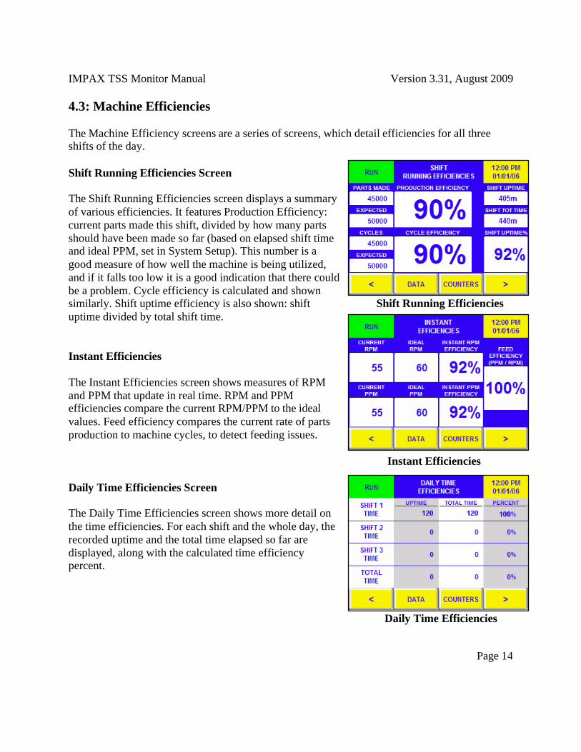
4.3: Machine Efficiencies The Machine Efficiency screens are a series of screens, which detail efficiencies for all three shifts of the day. Shift Running Efficiencies Screen The Shift Running Efficiencies screen displays a summary of various efficiencies. It features Production Efficiency: current parts made this shift, divided by how many parts should have been made so far (based on elapsed shift time and ideal PPM, set in System Setup). This number is a good measure of how well the machine is being utilized, and if it falls too low it is a good indication that there could be a problem. Cycle efficiency is calculated and shown similarly. Shift uptime efficiency is also shown: shift Shift Running Efficiencies uptime divided by total shift time. Instant Efficiencies The Instant Efficiencies screen shows measures of RPM and PPM that update in real time. RPM and PPM efficiencies compare the current RPM/PPM to the ideal values. Feed efficiency compares the current rate of parts production to machine cycles, to detect feeding issues. Instant Efficiencies Daily Time Efficiencies Screen The Daily Time Efficiencies screen shows more detail on the time efficiencies. For each shift and the whole day, the recorded uptime and the total time elapsed so far are displayed, along with the calculated time efficiency percent. Daily Time Efficiencies
IMPAX TSS Monitor Manual Version 3.31, August 2009
Page 15
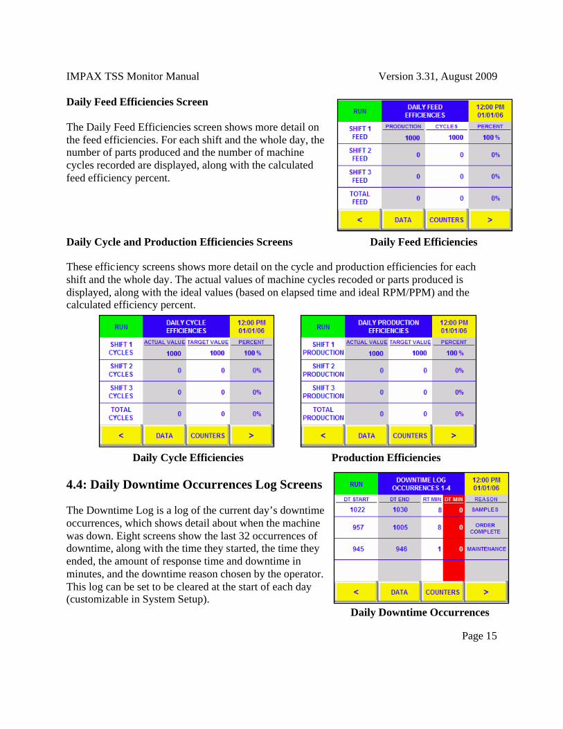
Daily Feed Efficiencies Screen The Daily Feed Efficiencies screen shows more detail on the feed efficiencies. For each shift and the whole day, the number of parts produced and the number of machine cycles recorded are displayed, along with the calculated feed efficiency percent. Daily Cycle and Production Efficiencies Screens Daily Feed Efficiencies These efficiency screens shows more detail on the cycle and production efficiencies for each shift and the whole day. The actual values of machine cycles recoded or parts produced is displayed, along with the ideal values (based on elapsed time and ideal RPM/PPM) and the calculated efficiency percent. Daily Cycle Efficiencies Production Efficiencies 4.4: Daily Downtime Occurrences Log Screens The Downtime Log is a log of the current day’s downtime occurrences, which shows detail about when the machine was down. Eight screens show the last 32 occurrences of downtime, along with the time they started, the time they ended, the amount of response time and downtime in minutes, and the downtime reason chosen by the operator. This log can be set to be cleared at the start of each day (customizable in System Setup). Daily Downtime Occurrences

IMPAX TSS Monitor Manual Version 3.31, August 2009
Page 16
5: Counters Screens This section discusses the use of the features in the Counters screens. The Counters screens are available by pressing the “Counters” button on any menu screen. This will activate the Counters Menu, which allows access to all of the Counters screens of the IMPAX TSS. To view any Counters screen, select its button. Counters Menu Entering, Clearing, and Changing Counts All of the counters in this section count up to a predefined quantity that can be edited at any time. To enter the quantity, press on it and enter a new number on the numeric keypad that appears. The quantity can be changed at any time in the same way, without clearing the current count (for example, to change the order quantity from 20,000 to 25,000 without losing track of the number of parts made so far). To clear the current count, press on the quantity and enter zero. This will clear the quantity and the current count, and turn off that counter until a new quantity is entered. Numeric Keypad 5.1: Order Counter Screen The Order Counter screen displays the current status of the machine and other useful information. Machine run/stop status is shown in the upper left corner, and RPM/PPM and current job and part are shown on the right. When a value is entered for Order Quantity, counters will also display the parts made and parts remaining until the quantity is reached. The percentage of the order complete and the number of minutes remaining (at the current PPM) are also shown. When the order quantity is reached, the Order Quantity Reached digital output is activated. Order Counter

IMPAX TSS Monitor Manual Version 3.31, August 2009
Page 17
5.2: Tool Counters Screens The Tool Counters screens provide nine tool counters that can be used to schedule tool replacements or other tasks. When a number is entered for the Expected Life, the counter will count up as parts are produced. When the Expected Life is reached, a special message will appear, letting the user know that it is time for the predefined task. When the Expected Life for a counter is cleared, that counter is disabled. When any tool counter’s expected life is reached, the Tool Counter Reached digital output is activated. The names used for tool counters 1-9 are downtime reasons 47-55, so the counter names can be customized for each machine. Tool Counters 5.3: Maintenance Counters Screens The Maintenance Counters screens provide nine additional counters. These can be used for other machine maintenance tasks or for user-defined reasons. They work identically to the tool counters. When any maintenance counter’s expected life is reached, the Maintenance Counter Reached digital output is activated. The names used for maintenance counters 1-9 are downtime reasons 56-64, so the counter names can be customized for each machine. Maintenance Counters 5.4: Daily Production Counts Screen The Production Counts screen displays the daily parts produced by each shift, and the current day's total parts produced. Machine cycles are also shown for each shift and the day. Additional information is available to managers through the Manager Menu, but this information is made available to provide a snapshot of daily production. Production Counts

IMPAX TSS Monitor Manual Version 3.31, August 2009
Page 18
6: Downtime Screens This section discusses the use of the Downtime screens. The Downtime screens become available when the machine is down. When the machine begins downtime, the Downtime Reasons Entry screen first appears, and other downtime features are available from that screen. 6.1: Downtime Reasons Entry Screen The Downtime Reasons Entry screen appears when the machine being monitored goes into downtime. It allows an operator to enter the reason why the machine is down, and will not let the machine start again until a reason is entered. Downtime is initiated when production stops for a set amount of time. This amount of time, the Downtime Delay Time, is customizable in System Setup. A timer will count up to the Downtime Delay Time whenever good parts are not detected through the Good Part input. If this condition lasts as long as the Downtime Delay Time, the machine will be considered down and a downtime reason must be entered to start the machine again. Downtime Reasons To enter a reason, first press the “Press to Respond” button to let the monitor know that the operator has responded (Operator response time is tracked and is available to managers). Then, after the downtime reason is addressed, press the button corresponding to the downtime reason. This will let the machine start. There are four screens of downtime reasons available via the “More Reasons” buttons, for a total of 64 reasons. If the wrong reason is entered, press the same button to cancel it and choose a new one. The reason is not recorded until the machine starts again.

IMPAX TSS Monitor Manual Version 3.31, August 2009
Page 19
Several other downtime options are available: 6.2: Downtime Menu The button marked “Downtime Menu” will display a menu of further options available. The first option, “Downtime Response Procedures,” will display instructions on how to respond to downtime. The other options (which are only available when a downtime reason has been entered) are buttons to go to the User Menu, Data Menu, and Counters Menu. To return to the Downtime Reasons screen afterwards, go to the Counters or Data menu and choose “Back to Downtime Reasons.” Downtime Menu 6.3: Part Change Downtime Reason One downtime reason button can be set to trigger a part-change screen (customizable in System Setup). When this reason is chosen, a set of screens will appear prompting for new job number, part number, operator ID, and other part fields. Entering this information and pressing Accept will log the new information under job information and return to the Downtime Reasons screen. Pressing Cancel will return to Downtime Reasons without saving any data. See the section on entering new job information through the User Menu for details. Entering New Part Data 6.4: Entering Additional Downtime Reasons After a downtime reason has been chosen, another button will be visible: “Press to Enter Additional Reason.” This can be used to enter multiple reasons per downtime occurrence. When pressed, a confirmation screen will appear, showing the chosen reason, and all other reasons that have been accepted for this occurrence. Pressing Accept will accept the chosen reason and allow the operator to choose another one. Pressing Cancel will return to Downtime Reasons without accepting the reason. New Downtime Confirmation
Press Button

IMPAX TSS Monitor Manual Version 3.31, August 2009
Page 20
7: User Menu Screens This section discusses the use of the IMPAX TSS features intended for machine operators. The User Menu is available by pressing the “User Menu” button on any menu screen. In it, there are a variety of function useful for machine operators. User Menu 7.1 User Guide Menu The User Guide Menu is a good place to start when new to the system: it provides online help screens that explain how to use the basic features of the IMPAX TSS. These instructions are broken into several categories, which may be selected from the menu. TSS Basics This screen contains some basic information about the IMPAX TSS and the User Guide Menu. User Guide Menu Navigation Buttons, Display Indicators, Entry Buttons These options lead to screens showing examples of all the different buttons and displays in the IMPAX TSS, with explanations for each. User Menu Info This set of screens contains descriptions of the features of the User Menu, and instructions on how to use them. Downtime Response Instructions This screen contains instructions on how to respond to machine downtime. Data Screens Help This screen contains descriptions of the Data screens, and instructions on how to use them. Counters Screens Help This screen contains descriptions of the Counters screens, and instructions on how to use them.
IMPAX TSS Monitor Manual Version 3.31, August 2009
Page 21
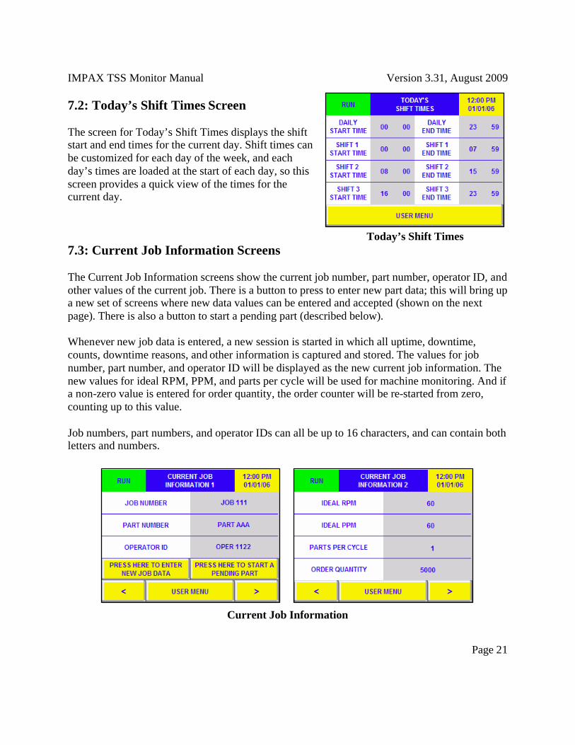
7.2: Today’s Shift Times Screen The screen for Today’s Shift Times displays the shift start and end times for the current day. Shift times can be customized for each day of the week, and each day’s times are loaded at the start of each day, so this screen provides a quick view of the times for the current day. Today’s Shift Times 7.3: Current Job Information Screens The Current Job Information screens show the current job number, part number, operator ID, and other values of the current job. There is a button to press to enter new part data; this will bring up a new set of screens where new data values can be entered and accepted (shown on the next page). There is also a button to start a pending part (described below). Whenever new job data is entered, a new session is started in which all uptime, downtime, counts, downtime reasons, and other information is captured and stored. The values for job number, part number, and operator ID will be displayed as the new current job information. The new values for ideal RPM, PPM, and parts per cycle will be used for machine monitoring. And if a non-zero value is entered for order quantity, the order counter will be re-started from zero, counting up to this value. Job numbers, part numbers, and operator IDs can all be up to 16 characters, and can contain both letters and numbers.
Current Job Information

IMPAX TSS Monitor Manual Version 3.31, August 2009
Page 22
Entering New Part Data 7.4: Scrap Entry Screen The Scrap Entry Screen allows entry of scrap part counts for the current job. The currently active job number, part number, and operator ID are shown, along with an entry field for scrap part count (in red). Any scrap entered in this field will be saved with the part/operator session. Scrap Entry 7.5: Message Screen The Message screen provides a place to store a user-enterable message. The message can be used for communication through the IMPAX TSS network: any message entered here will be visible to a manager using IMPAX TSS networking software. A new message can be entered by pressing on the current message, and then typing in the desired text. Message Screen
IMPAX TSS Monitor Manual Version 3.31, August 2009
Page 23
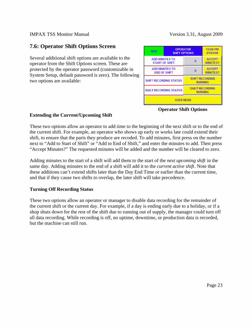
7.6: Operator Shift Options Screen Several additional shift options are available to the operator from the Shift Options screen. These are protected by the operator password (customizable in System Setup, default password is zero). The following two options are available: Operator Shift Options Extending the Current/Upcoming Shift These two options allow an operator to add time to the beginning of the next shift or to the end of the current shift. For example, an operator who shows up early or works late could extend their shift, to ensure that the parts they produce are recoded. To add minutes, first press on the number next to “Add to Start of Shift” or “Add to End of Shift,” and enter the minutes to add. Then press “Accept Minutes?” The requested minutes will be added and the number will be cleared to zero. Adding minutes to the start of a shift will add them to the start of the next upcoming shift in the same day. Adding minutes to the end of a shift will add it to the current active shift . Note that these additions can’t extend shifts later than the Day End Time or earlier than the current time, and that if they cause two shifts to overlap, the later shift will take precedence. Turning Off Recording Status These two options allow an operator or manager to disable data recording for the remainder of the current shift or the current day. For example, if a day is ending early due to a holiday, or if a shop shuts down for the rest of the shift due to running out of supply, the manager could turn off all data recording. While recording is off, no uptime, downtime, or production data is recorded, but the machine can still run.

IMPAX TSS Monitor Manual Version 3.31, August 2009
Page 24
7.7: Pending Parts Screens The Pending Parts screen shows up to four upcoming parts that have been entered by a machine operator or by a manager using IMPAX TSS networking software. These parts can be viewed and edited by pressing on the “View Part Details” buttons. Pressing the “Start Part” button next to a part will bring up the new part screen, with the data fields filled in with the pending part’s data. Pending parts can also be started through a button on the Current Job Information screen.
Pending Parts 7.8: Operator Sign-In Screen The button for Operator Sign-In jumps to the screens for entering new job information (described above), which are also used to enter a new operator ID. Additionally, the IMPAX TSS can be set to enforce operator logins by shift (customizable in System Setup). If this option is on, then at the start of each scheduled shift, an operator shift login screen will appear. This screen allows an operator to login with their ID, and to update the values for current job number and part number. Also, the operator cannot leave this screen until they enter an operator ID.
Operator New Shift Login Screens

IMPAX TSS Monitor Manual Version 3.31, August 2009
Page 25
8: History Menu This section discusses the use of the IMPAX TSS features intended for managers. The History Menu is available from the Start Menu screen. It is protected by the manager password (customizable in System Setup, default password is zero). In the menu, there is a Machine History Menu that provides access to all saved machine data, and also the Part and Operator History Menu, which allow access to saved data for previous part numbers and operators. History Menu 8.1: Machine History Menu The Machine History Menu provides access to screens that show all the machine data that has been collected. To view the data, select either Daily, Weekly, Monthly, or Yearly Machine Data. This will bring up the data for the selected period. Machine History Menu Each of the Daily, Weekly, Monthly, and Yearly Machine Data sections is presented similarly to the daily data screens available to the operator. Uptime, downtime, downtime reasons, and production counts are all available, along with response times. Additionally, there is a Response Times screen, which shows the total operator response times for each shift and totals for daily, weekly, monthly, and yearly periods. Machine Response Times

IMPAX TSS Monitor Manual Version 3.31, August 2009
Page 26
8.2: Part and Operator History Menu The Part and Operator History Menu provides access to screens that show machine data for the current part and operator, and the prior five part/operator combinations (Each time a new job, part, or operator starts, a new session is started). Page 1 and 2 of the Part and Operator History Menu show these sessions and their start and end dates/times. Select one of these sessions by pressing on its button on the left to see a menu of data screens for that session. The menu buttons and arrows can be used to navigate through these screens. Part History Menu Current Session Menu
IMPAX TSS Monitor Manual Version 3.31, August 2009
Page 27
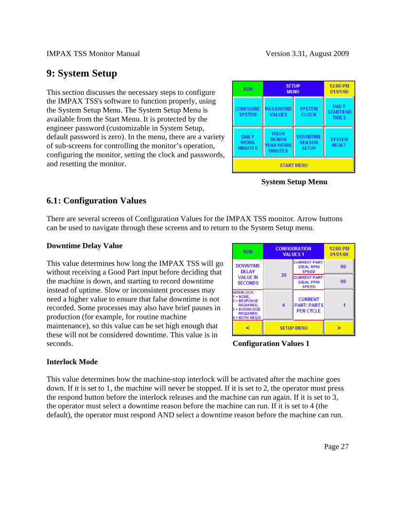
9: System Setup This section discusses the necessary steps to configure the IMPAX TSS's software to function properly, using the System Setup Menu. The System Setup Menu is available from the Start Menu. It is protected by the engineer password (customizable in System Setup, default password is zero). In the menu, there are a variety of sub-screens for controlling the monitor’s operation, configuring the monitor, setting the clock and passwords, and resetting the monitor. System Setup Menu 6.1: Configuration Values There are several screens of Configuration Values for the IMPAX TSS monitor. Arrow buttons can be used to navigate through these screens and to return to the System Setup menu. Downtime Delay Value This value determines how long the IMPAX TSS will go without receiving a Good Part input before deciding that the machine is down, and starting to record downtime instead of uptime. Slow or inconsistent processes may need a higher value to ensure that false downtime is not recorded. Some processes may also have brief pauses in production (for example, for routine machine maintenance), so this value can be set high enough that these will not be considered downtime. This value is in seconds. Configuration Values 1 Interlock Mode This value determines how the machine-stop interlock will be activated after the machine goes down. If it is set to 1, the machine will never be stopped. If it is set to 2, the operator must press the respond button before the interlock releases and the machine can run again. If it is set to 3, the operator must select a downtime reason before the machine can run. If it is set to 4 (the default), the operator must respond AND select a downtime reason before the machine can run.
IMPAX TSS Monitor Manual Version 3.31, August 2009
Page 28
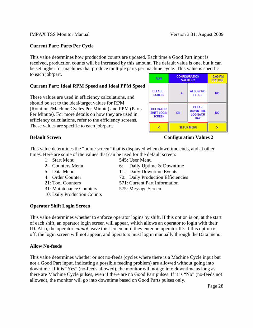
Current Part: Parts Per Cycle This value determines how production counts are updated. Each time a Good Part input is received, production counts will be increased by this amount. The default value is one, but it can be set higher for machines that produce multiple parts per machine cycle. This value is specific to each job/part. Current Part: Ideal RPM Speed and Ideal PPM Speed These values are used in efficiency calculations, and should be set to the ideal/target values for RPM (Rotations/Machine Cycles Per Minute) and PPM (Parts Per Minute). For more details on how they are used in efficiency calculations, refer to the efficiency screens. These values are specific to each job/part. Default Screen Configuration Values 2 This value determines the “home screen” that is displayed when downtime ends, and at other times. Here are some of the values that can be used for the default screen: 1: Start Menu 545: User Menu 2: Counters Menu 6: Daily Uptime & Downtime 5: Data Menu 11: Daily Downtime Events 4: Order Counter 70: Daily Production Efficiencies 21: Tool Counters 571: Current Part Information 31: Maintenance Counters 575: Message Screen 10: Daily Production Counts Operator Shift Login Screen This value determines whether to enforce operator logins by shift. If this option is on, at the start of each shift, an operator login screen will appear, which allows an operator to login with their ID. Also, the operator cannot leave this screen until they enter an operator ID. If this option is off, the login screen will not appear, and operators must log in manually through the Data menu. Allow No-feeds This value determines whether or not no-feeds (cycles where there is a Machine Cycle input but not a Good Part input, indicating a possible feeding problem) are allowed without going into downtime. If it is “Yes” (no-feeds allowed), the monitor will not go into downtime as long as there are Machine Cycle pulses, even if there are no Good Part pulses. If it is “No” (no-feeds not allowed), the monitor will go into downtime based on Good Parts pulses only.

IMPAX TSS Monitor Manual Version 3.31, August 2009
Page 29
Clear Downtime Log Each Day This value determines if the Downtime Log is cleared at the start of each day. If this is set to “Yes,” the log is cleared. If it is set to “No,” previous days’ occurrences will stay in the log. Downtime Code That Excludes Response Time If this value is set to a non-zero number, then when a downtime code with matching number is chosen, response time is not recorded. This is useful in settings where circumstances require an immediate response, so that the operator cannot respond to the monitor right away. Setting this value to zero will disable this feature. Downtime Code for Part Change Configuration Values 3 If this value is set to a non-zero number, then when the downtime reason with matching number is chosen, a special data entry screen will appear, allowing the user to enter a new job number, part number, and operator ID. Since information is saved for parts/operators, this can be useful to ensure a new number is entered when the machine is down for part/operator changeovers. Setting this value to zero will disable this feature: part data will still be tracked when new numbers are entered, but no special screen will be shown when a certain downtime code is entered. Copy PPM to RPM: This value should be set based on whether the TSS has separate sensors for good parts (used to calculate PPM) and for machine cycles (used to calculate RPM). If there is only one sensor, this setting should be set to “Yes,” so the TSS will copy the PPM value into the RPM value and will correct the machine efficiencies. If there are separate sensors, this setting should be set to “No,” so the TSS calculates PPM and RPM independently. Good Part Inputs Needed This value is used to determine when to consider a machine cycle as a good part. If it is set to 1, whenever there is a pulse on the Good Part input, a part will be recorded. If it is set to 2 (or 3), pulses on the Good Part input will be ignored unless the Good Part Condition 1 (and 2) inputs are also currently active. The conditional inputs can therefore be used to make sure that good parts are only counted when the machine is in a certain mode, or when a certain switch is on, etc.

IMPAX TSS Monitor Manual Version 3.31, August 2009
Page 30
6.2: System Passwords This screen allows setting the system passwords, to control access to various monitor features. Passwords start initialized to 0. The three passwords are: Operator Password: for accessing Operator Shift Options Manager Password: for entering History Menu Engineer Password: for entering System Setup Menu Password Values 6.3 System Clock: Set Time and Date This screen allows setting the monitor’s time and date. To set the time, enter the desired hour and minute (in 24-hour time), and press the button “Press to Set Time.” To set the date, enter the desired month, day, year, and day of the week, and press the button “Press to Set Date.” The entered time or date will be updated immediately in the upper-right corner of the screen. If the date is changed, the monitor will load the daily times from the new date. System Clock Note: It is important to enter the correct day of the week, or weekday start/end times will not be loaded correctly. The days of the week are numbered zero through six, as follows: 0 = Sunday, 1 = Monday, 2 = Tuesday, 3 = Wednesday, 4 = Thursday, 5 = Friday, 6 = Saturday

IMPAX TSS Monitor Manual Version 3.31, August 2009
Page 31
6.4: Daily Start/End Times There are eight screens of Start/End Times, one for each day of the week, and one for the Current Day. These values determine the start/end times of the daily period and three daily shifts, which are used to track uptime/downtime. When a day ends, the next day’s times are loaded and placed into the Current Day times. Times are also loaded whenever the monitor is turned on. Start/End times should be set carefully! The monitor will only record data when the current time is within the defined daily period AND within a shift period. Anything that happens outside of these windows will be ignored. If times are set incorrectly, data loss/corruption can occur. The monitor should remain on during work days! To correctly track data and load the right times each day, the monitor should be turned on before the Day Start Time of each calendar day. All times are in 24-hour time: hours range from 0-23, and minutes range from 0-59. The time 0:00 is 12:00am, and 23:59 is 11:59pm. To enter the daily period, enter the hour and minutes for the Day Start Time and the Day End Time. The daily period will last from the first second of Day Start Time to the last second of Day End Time. For example, a 10:00am to 4:00pm shift should be entered as 10:00 to 15:59. The Day Start Time should be less than the Day End Time, unless the daily period goes through midnight. For example, a 10:00pm to 4:00am shift would be 22:00 to 3:59. No day may last more than 24 hours. Adjacent days should not overlap. Note: if the daily period is set to begin at or after 18:00 (6:00pm), the day will actually begin at that time on the previous calendar day (a Day Start Time of 22:00 will start the previous day at 10pm). Shift start and end times are entered similarly. Shifts can go through midnight, but should not go through the start or end of the daily period. All active shifts should fall within the daily period. Two shifts should not overlap. A shift can be turned off by setting its start and end times to 0:00. Sample start and end times are shown below: first for a 24-hour day with three 8-hour shifts, and second for a 20-hour day with two 10-hour shifts (where shift two goes through midnight):

IMPAX TSS Monitor Manual Version 3.31, August 2009
Page 32
Disabling Days A day can be disabled by setting its start and end times to be equal. This will turn off all uptime/downtime monitoring on that day. Even when a day is disabled, the TSS checks for the start of a week/month/year at that day's start time. This means that disabled days' times should be set so that no day is skipped. For example, if Friday's shifts run until 1:59am Saturday morning, Saturday's start and end times should be set to 02:00 or later so that if Saturday starts a new month, monthly data will be reset correctly. For another example, if Monday's shift 1 starts at 10:00pm Sunday night, Sunday's end time should be set earlier than 10:00pm, so that Monday's times can be loaded correctly. Current Day’s Times The Current Day times screen shows the times that the machine is currently using. At the end of each day, these times are loaded for the next day. Operators can make simple changes to these times through Operator Shift Options: they can add minutes to the beginning or end of a shift. The times can also be manually edited through System Setup: they appear in Start/End Times after Saturday’s times. Current Day Start & End Times If the monitor ever becomes “stuck” with the wrong times, and will not load new times, the current day’s times can be manually edited to free the monitor to run (Times can be edited through the Current Day page in Start/End Times in System Setup). If the monitor will not track uptime/downtime even if the current time is within a day and shift period in the current day’s times, the monitor can be turned off and on again to force it to re-load today’s times, and then the times can be edited manually.

IMPAX TSS Monitor Manual Version 3.31, August 2009
Page 33
6.5: Daily Work Minutes These values represent the total amount of available minutes in each shift and the daily period, for each day of the week. These numbers are used to calculate the percentages for uptime and downtime. Calculate the total number of minutes available and enter them to ensure the calculated percentages are accurate. Daily Work Minutes 6.6: Weekly, Monthly, Yearly Work Minutes These values are similar to the daily work minutes, but are for the weekly, monthly, and yearly periods. They are also used to calculate percentages for uptime and downtime. Calculate the total number of minutes available and enter them to ensure the calculated percentages are accurate. Other Work Minutes 6.7: Downtime Reason Setup This screen can be used to customize what text is used for downtime reasons. The text to use for the downtime reasons can be changed by pressing on the reason to change, and then typing the reason using the on-screen keyboard. Note that downtime reasons 47 through 64 are used as the names of Tool Counters 1-9 and Maintenance Counters 1-9, in that order. Downtime Reason Setup

IMPAX TSS Monitor Manual Version 3.31, August 2009
Page 34
6.8: System Reset This feature resets the IMPAX TSS's memory, clearing machine data. To use it, simply press the “Reset Button” (It will say “Reset Complete” when pressed). This will clear all stored daily, weekly, monthly, and yearly values. Current job information and all counters will also be cleared. System Reset

IMPAX TSS Monitor Manual Version 3.31, August 2009
Page 35
7: Input and Output Reference Sensor Inputs:
X0 PLC terminal: Good-part input X1 PLC terminal: Machine-cycle input X4 PLC terminal: Good part condition 1 (See section 2.3 for details) X5 PLC terminal: Good part condition 2 (See section 2.3 for details) +V PLC terminal: +24V power for proximity sensors C0 PLC terminal: Ground for 24V PLC inputs
Relay Outputs:
NO-0 PLC terminal: Interlock relay, normally open NC-0 PLC terminal: Interlock relay, normally closed C-0 PLC terminal: Interlock relay, common NO-1 PLC terminal: Order Quantity Reached relay, normally open C-1 PLC terminal: Order Quantity Reached relay, common NO-2 PLC terminal: Tool Counter Reached relay, normally open C-2 PLC terminal: Tool Counter Reached relay, common NO-3 PLC terminal: Maintenance Counter Reached relay, normally open NC-3 PLC terminal: Maintenance Counter Reached relay, normally closed C-3 PLC terminal: Maintenance Counter Reached relay, common