impact of wind power plants on voltage control of power system · moumita sarkar , mufit altin,...
TRANSCRIPT
Impact of Wind Power Plants on Voltage Controlof Power System
Moumita Sarkar∗, Mufit Altin, Anca D. Hansen, Poul E. SørensenDepartment of Wind Energy
Technical University of DenmarkRisø, 4000 Roskilde, Denmark
∗Email: [email protected]
Abstract—High penetration of renewable energy sourcesposes numerous challenges on stability and security of powersystems. Wind power plants (WPPs) of considerable size whenconnected to a weak grid by long transmission line results inlow short circuit ratio at the point of connection. This mayresult in both transient voltage fluctuations and poor steady-state voltage profile at the point of connection. In this paper,transient and steady-state voltage support from WPPs areinvestigated. Low voltage ride through capability of WPP isstudied for two different control modes namely, V control andQ control, during transient voltage dips. Steady-state analysis isperformed for stressed system conditions. Results are validatedthrough simulation in a detailed power system model.
I. INTRODUCTION
Penetration of Renewable Energy Sources (RES) is in-creasing in electrical power systems across the globe. Windis one of the largest contributors supplying reliable and af-fordable energy [1]. As of 2015, approximately 4% of globalenergy is supplied by wind [2]. In 2016, wind energy met10.4% of the power demand of the European Union. Windpenetration level is substantial in some European Mem-ber States like – Denmark (42%), Ireland (27%), Portugal(25%), Spain (19%), Germany (16%), UK (12.4%) [3]. Withhigh penetration of RES, most conventional synchronousgenerators are being replaced by converter connected non-synchronous generators like wind turbines (WT). This makespower systems weak due to low short circuit power avail-able and low system inertia. Weak power systems togetherwith variability of RES generations pose various researchchallenges on power system stability and security. One suchchallenge being voltage stability, particularly when a largeWPP is connected to the grid through a long transmissionline.
Variability of wind speed causes changes in active poweroutput of WPP. This may lead to changes in reactive poweroutput and consequently voltage at the Point of Connection(PoC). Support from WPPs may be beneficial and required todeal with system contingencies as well as normal operationof power system. Most Transmission System Operators(TSO) specify reactive power requirements for both tran-sient and steady-state conditions for WPPs in order to beconnected to their respective grid. As per Danish grid codespecified by Danish TSO Energinet, WPPs are required tofulfil low voltage ride through (LVRT) and inject reactivecurrent to support voltage dip at PoC during transientconditions [4]. During steady-state operation, three differentmodes of reactive power and voltage control functions fromWPPs are possible namely, reactive power control, voltage
control and power factor control. These three control modesare mutually exclusive and the requirements are specified inthe grid code.
Modern variable-speed controllable WTs can be of twotypes – doubly fed induction generator (DFIG) based WTs(referred as Type 3 WTs) and fully rated converter basedWTs (referred as Type 4). Type 4 WTs are only consideredin this paper. Fully rated converter decouples WT generatorfrom the grid as well as enables independent active and reac-tive power control. Independent reactive power support fromType 4 WTs can help in LVRT support [5]. Additionally,converters can provide very fast response which might becrucial in a low inertia, low short circuit power system [6].
At steady-state, reactive power available from WPPs de-pend on the active power generated. Grid code requirementsas specified by TSOs are minimum requirements that theWPP has to fulfill in order to connect to the grid. Dependingon WT technology, WPPs may be able to deliver additionalreactive power [7]. Since individual WT’s attempt to controlvoltage at individual connection points can lead to instabilityissues, coordinated voltage control at WPP level can behelpful [8]. Centralised WPP control can also be usefulin this direction as suggested by Hansen et. al. [9]. Thereare other centralised and decentralised WPP level controlstrategies also available [10].
In this paper, Type 4 WT model as described in IEC61400-27-1 [11] has been developed and extended to accountfor aerodynamic behaviour due to variation in wind speed.Performance of the extended model is illustrated for changesin wind speed and reactive power setpoint. Transient as wellas steady-state studies are performed on the extended modelconnected to a power system grid model.
Organisation of this paper is as follows: Section II de-scribes the extended WT model and illustrates its perfor-mance. Section III illustrates transient and steady-state sim-ulation studies performed. Section IV concludes the paper.
II. WIND TURBINE MODEL
A. IEC Model
Generic IEC 61400-27-1 WT models have been developedby International Electrotechnical Commission (IEC) [11]for short term stability studies. These models are used tosimulate typical WT response during dynamic power systemevents [14]. Based on speed and power control methodolo-gies, WT generator configurations are classified into fourcategories [12] :

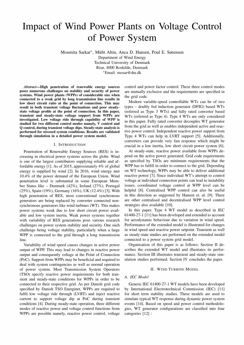
Fig. 1: Extended Type 4B IEC Model [13]
1) Type 1 represent fixed-speed WTs that are directlyconnected to the grid. For these type of WTs, squirrelcage induction generator (SCIG) are typically used .
2) Type 2 represent variable-speed WTs directly con-nected to the grid. Typically wound rotor inductiongenerator (WRIG) with an additional variable rotorresistance is used in these type of configurations. Thesevariable rotor resistances allow control of slip andpower output of the generators.
3) Type 3 represent variable speed WTs with DFIGs.In this type, stator is directly connected to the gridwhereas the rotor is connected to the grid via back-to-back power electronic converter.
4) Type 4 represent variable speed WTs connected tothe grid by back-to-back full scale power electronicconverters. The full scale converters decouple gener-ator from the grid. Type 4 WTs can have permanentmagnet synchronous generator (PMSG), wound rotorsynchronous generator (WRSG) or WRIG, connectedto the rotor shaft with or without gearbox.
IEC 61400-27-1 describes modular structure for all four WTconfigurations. Generic modular structure of WTs consists ofthe following blocks: aerodynamic, mechanical, generator,electrical equipment, grid protection and control. Two typesof Type 4 WT model has been specified in IEC 61400-27-1:
1) Type 4A configuration neglects aerodynamic and me-chanical blocks of the generic WT modular structure.
2) Type 4B configuration includes a 2-mass mechanicalmodel but neglects the aerodynamic block.
In this work, Type 4B WT configuration has been used.For short term stability studies, wind speed can be as-
sumed constant. However for long term stability analysis,variability of wind speed needs to be considered. Type 4BIEC model have been extended by Hansen et.al. [13] toinclude aerodynamic behaviour of rotor, such that the impact
of wind speed variability can be assessed.
B. Extended Type 4B IEC Model – inclusion of aerodynam-mic block
The extended model consists of a wind speed block, pitchcontroller, aerodynamic block and Maximum Power PointTracking (MPPT) in addition to mechanical, active powercontrol, reactive power control and static generator blockas specified in IEC Type 4B model structure. Fig. 1 showsstructure of the extended IEC model. This model can alsocapture the dynamic behaviour of WTs when there is changein active power setpoint. The wind farm controller interfaceshown in Fig. 1 depicts that the WT model can recieve inputsignals (like active and reactive power setpoints, overproduc-tion requirement signal, etc) from WPP controller. Differentblocks of the model will be illustrated in the followingsubsections.
1) Pitch control block: It is needed to limit the activepower output from WT at rated power output during highwind speed conditions [15]. During low wind speed condi-tions, pitch angle remains constant at optimal pitch anglevalue. The block diagram of the pitch controller is shownin Fig. 2. The pitch controller consists of an antiwind-up PI
Fig. 2: Pitch control block
controller and a servomechanism with pitch angle limitationand rate of change of angle limitation [13]. The PI controlleruses the error between the actual and reference generatorspeed to determine the reference pitch angle. When nominalgenerator speed is reached, rotor speed is limited by the pitchcontrol block by increasing pitch angle.

2) Aerodynamic block: It computes aerodyanamic poweroutput of the WT based on wind speed and pitch angle. Therelation determining aeodynamic power extracted from wind[15] is given by (1).
Paero =1
2ρπR2U3Cp(λ, θ) (1)
where,ρ = air density in kg/m3
R = rotor diameter in mU = wind speed in m/sθ = pitch angleλ = tip-speed ratioCp = power coefficient
Tip-speed ratio, λ, is defined as ratio of speed of tip of bladeto wind speed and is illustrated in (2)
λ =ωwtrR
U(2)
where ωwtr is rotor speed. Power coefficient, Cp, is functionof tip-speed ratio and pitch angle. It illustrates change ofaerodynamic power depending on wind speed and pitchangle. Cp is modelled as a two dimensional look-up table.
3) Mechanical block: A two mass mechanical model asproposed in IEC 61400-27-1 is used. Block diagram of themechanical model [14] is shown in Fig. 3. The two mass
Fig. 3: Two mass mechanical model block [16]
model is capable of capturing oscillations induced by windgusts and change in active power setpoints which causesimbalance of electrical and mechanical torque. Stiffness(ksh) and damping (csh) of shaft as well as inertia of WTrotor (Hrot) and inertia of generator (Hgen) are consideredin the model. Airgap power (Pairgap) is measured as theelectrical power output of the static generator.
4) MPPT table: MPPT is implemented as a lookup tablewhich determines reference power output of generator as afunction of generator speed. This table ensures that optimalaerodynamic power is being extracted by keeping the turbineworking at maximum power coefficient Cp, until nominalrotational speed is reached [16].
5) Active power(P) control block: P control block imple-mented here differs from the P control block described inIEC model. The P control block implementation is shown inFig. 4. A low pass mesurement filter is used to filter highfrequency fluctuations in measured active power, Pmeas. Theerror signal between reference and measured active power isthen passed through an anti-windup PI controller to obtainreference active current signal, ipcmd.
Fig. 4: Active power control block [13]
6) Reactive power(Q) control block: The Q control blockimplemented is similar to that illustrated for IEC Type 4BWT model. It is illustrated in Fig. 5. Different types of
Fig. 5: Reactive power control block
Q control modes can be implemented using this block:voltage control, reactive power control, power factor control,open/closed loop control. The reference signal to the Qcontrol block can be voltage, reactive power or power factorsetpoint. A low pass measurement filter is used to filterhigh frequency fluctuations in measured voltage or reactivepower signal. Based on the chosen Q control mode, referenceand measured signal are chosen. Error between measuredand refernce signal are then passed through an anti-windupPI controller to generate Iqbase signal. When voltage atPoC drops below threshold voltage due to sudden systemdisturbances, Q controller switches to LVRT mode. In LVRTmode, more reactive power support from WT is required tosupport the PoC voltage. A voltage scaling factor is usedto determine the voltage dependent reactive current duringLVRT, Ifault. Some grid codes require to inject post-faultreactive power for a specified time period. This is determindby the post-fault current contribution block and is referredhere as Iqpost. In IEC Q control block, there are provisionfor three different types reactive current injection during faultand in post-fault period:
• voltage dependent reactive current during fault• pre-fault reactive current value + voltage dependent
reactive current during fault• pre-fault reactive current value + voltage dependent re-
active current during fault and pre-fault reactive currentvalue + additional constant reactive current post-fault
During normal operation, iqcmd equals to Iqbase. Duringfault, iqcmd equals to Iqfault which is calculated as per thechosen LVRT current injection mode. In post-fault period, ifpost-fault reactive power injection is required, iqcmd is setto sum of Iqpost and Iqbase else it is set to Iqbase.
7) Static generator block: It consists of generator refer-ence current limiter model, phase locked loop (PLL) andstatic generator block. Fig. 6 illustrates the block. The

Fig. 6: Static generator block [16]
static generator is used as a current source here, hence thereference active and reactive current input together with thephase information provided by the PLL is used as input tothe static generator.
C. Performance of Extended Type 4B IEC Model
To evaluate model performance, a simple two bus systemas shown in Fig. 7 is used. The test system includes a 2 MW
Fig. 7: 2 bus test system for model performance evaluation
Type 4 WT connected to grid through step up transformerand transmission line. Aim of these performance studiesare to show that the extended IEC Type 4B model canrespond to wind speed variability. Also different modes of Qcontrol, namely, voltage control and reactive power controlare evaluated here. For these purposes, the following twosimulation studies are done:
• Step changes in wind speed are applied• Step changes in reactive power setpoint are applied
Results of simulation studies are illustrated in followingsubsections.
1) Case 1 – step changes in wind speed: To illustrateperformance of the model for varying wind speeds, stepchanges in wind speed are applied from 6m/s to 18m/s insteps of 1m/s every 30s. Results of the simulation – windspeed, pitch angle, generator speed and active power areshown in Fig. 8. Step changes in wind results in changesin pitch angle, generator speed and active power outputfrom WT. It can be observed that below rated wind speedof 12m/s, pitch angle does not change. When wind speedreaches rated speed, pitching of blades start in order to limitrotor speed as generator speed limit is reached. As windspeed increases above rated speed, pitch angle increases tolimit the power output. It can be observed that, generatorspeed increases in steps until rated generator speed is reachedat rated wind speed. Above rated wind speed, generatorspeed remains constant at 1 p.u. Active power output fromWT increases from about 0.2 pu at 6m/s to 1 p.u. at 12 m/s.Beyond rated wind speed, active power output is maintainedconstant at 1 p.u.
0 50 100 150 200 250 300 350 4005
101520
Win
d S
peed
[m
/s]
0 50 100 150 200 250 300 350 400
0
10
20
Pitch
[deg]
0 50 100 150 200 250 300 350 400
0.8
1
1.2
G
enerato
r
speed [p.u
.]
0 50 100 150 200 250 300 350 400Time [s]
0
0.5
1
Active p
ow
er
[p.u
.]
Fig. 8: Model performance for increasing wind speed in stepsof 1m/s from 6m/s to 18m/s: wind speed [m/s], pitch angle[deg], generator speed [pu] and active power [pu]
2) Case 2 – step changes in reactive power setpoint: Todemonstrate output of Q controller block, step changes of0.1 p.u. in reactive power setpoint are performed at intervalsof 20s. In this case, Q controller response for two differentmodes of reactive power control – Q control and V control– are studied. Wind speed is kept constant at 13 m/s. Fig.9 shows the voltage at PoC, generator speed, active poweroutput and reactive power output of WT when operated inQ control mode. It can be seen from Fig. 9, reactive power
0 20 40 60 80 100 120 140 160 180
0.995
1
VP
oC
[p.u
.]
0 20 40 60 80 100 120 140 160 180
1
1.001
1.002
G
enerato
r
speed [p.u
.]
0 20 40 60 80 100 120 140 160 1800.998
1
1.002
A
ctive
p
ow
er
[p.u
.]
0 20 40 60 80 100 120 140 160 180Time [s]
-1-0.6-0.20.2
R
eactive
pow
er
[p.u
.]
Q measuredQ reference
Fig. 9: Model performance for step changes in Q setpointin Q control mode: voltage at PoC [p.u.], generator speed[p.u.], active power [p.u.] and reactive power [p.u.]
output follows the reactive power setpoint until maximum orminimum limit of the controller is reached. Voltage at PoCchanges according to reactive power output of WT. Activepower output remains constant since it is not affected by

change in reactive power output. Active and reactive powercan be controlled independently. Fig. 10 shows voltage atPoC, generator speed, active power output and reactivepower output of WT when operated in V control mode.In this mode, the Q controller follows the voltage setpoint
0 20 40 60 80 100 120 140 160 180
0.995
1
VP
oC
[p.u
.]
0 20 40 60 80 100 120 140 160 180
1
1.001
1.002
G
enerato
r
speed [p.u
.]
0 20 40 60 80 100 120 140 160 1800.998
1
1.002
A
ctive
p
ow
er
[p.u
.]
0 20 40 60 80 100 120 140 160 180Time [s]
-1-0.6-0.20.2
R
eactive
pow
er
[p.u
.]
Q measuredQ reference
Fig. 10: Model performance for step changes in Q setpointin V control mode: voltage at PoC [p.u.], generator speed[p.u.], active power [p.u.] and reactive power [p.u.]
and tries to maintain the PoC voltage at set reference value.Reactive power reference setpoint is not considered.
These studies show that relation between pitch angleand generator speed with variation in wind speed can besimulated using the extended IEC model. These studies alsoillustrate operation of the reactive power cntroller in twodifferent modes – V control and Q control. It can be observedthat steady-state limits of the pitch, active and reactive powercontroller can be captured in order to perform long-termstability studies.
III. SYSTEM STUDIES
System studies are done using the extended IEC Type4B model connected to a detailed network. Transient per-formance of the model is evaluated when a three-phase faultoccurs in the grid. Steady-state performance of the modelis evaluated for stressed system condition when a line hasbeen disconnected due to a permanent fault.
A. Simulation System
The wind power grid model as shown in Fig. 11 ismodelled in DIgSILENT PowerFactory for simulation stud-ies. This reduced but realistic grid model was proposed byAkhmatov et. al. in [17], [18] for voltage stability studies.The system consists of 4 central power plants and anaggregated model of WPP of 300MW. The WPP comprisesof extended Type 4B WT model as discussed in the SectionII-B. The WPP is connected to grid at bus 111 by a 150km long transmission line. The short circuit ratio (SCR) asdefined by Gavrilovic in [19] is calculated at bus 115 whichis the PoC. It is obtained as 1.52. As per IEEE guidelines forAC/DC systems [20], a system with SCR less than 2 can be
Fig. 11: Simulation System
defined as very weak system. Thus the bus 111 highlightedin grey in Fig. 11 is a weak bus prone to voltage fluctuations.Both dynamic and steady-state studies are performed on thesystem for a three-phase bolted fault at line L1 connectingbus 111 to bus 108. Line L1 is opened to clear the fault
B. Grid Code Requirements
For these simulation studies, limits of voltage and reactivecurrent output from WPP are set according to the Danishgrid code requirements specified in [4]. For abnormal op-erating conditions with transient voltage dip due to systemfaults, voltage dip tolerance requirement and reactive currentinjection requirement are illustrated in Fig. 12 and Fig 13respectively. During LVRT, delivery of reactive power is
Fig. 12: Voltage dip tolerance requirement [4]
given higher priority than active power. During voltage dips,WPP must be capable of providing reactive current as shown

Fig. 13: Reactive current injection requirement [4]
in Fig. 13 within 100ms. If voltage drops below 0.5 p.u.,WPP is required to deliver reactive current equal to 100%of its nominal current. WPP is required to withstand voltagedips of 20% at PoC and stay connected to the grid for 0.5sas shown in Fig. 12. If operating point moves in Area Cshown in Fig. 12, WPP is allowed to disconnect.
For steady-state operations, grid code requirement of reac-tive power in relation to active power and normal operatingvoltage are illustrated in Fig. 14 and Fig. 15 respectively.Operating point of WPP for delivery of reactive power must
Fig. 14: Q in relation to active power for steady-stateoperation [4]
Fig. 15: Q in relation to voltage for steady-state operation[4]
lie in the shaded region. It can be observed from Fig. 14that the reactive power requirement from WPP varies withactive power delivered by the WPP. Between 0.2 p.u. and 0.8p.u. of active power, maximum reactive power requirement
lies between ± 0.33 p.u. Between 0.8 p.u. and 1 p.u. ofactive power, reactive power requirement decreases from ±0.33 p.u. to ± 0.228 p.u. Fig. 15 shows delivery of reactivepower is required between 0.9 p.u. and 1.06 p.u. of normaloperating voltage.
C. Case Studies
1) Dynamic Analysis – Low Voltage Ride Through: Inthis case study, LVRT capability of the WPP is studiedfor V and Q control modes. A three-phase fault occurs online L1 at t = 5s. The voltage at PoC, reactive currentreference set by the Q controller and the reactive poweroutput of WPP without LVRT and with LVRT – for Vcontrol and Q control modes – are shown in Fig. 16. When
4.5 5 5.5 6 6.50
0.5
1
1.5
VP
oC
[p.u
.]
Without LVRTV ControlQ Control
4.5 5 5.5 6 6.5-1
-0.5
0
0.5
1
I qre
f [p.u
.]Without LVRTV ControlQ Control
4.5 5 5.5 6 6.5Time [s]
0
0.5
1
QW
PP [p.u
.]
Without LVRT 1Without LVRT2V Control
Fig. 16: LVRT for V and Q control modes
there is no LVRT support from WPP, there is no priorityof reactive power delivery during voltage dips. Reactivecurrent reference remains same as pre-fault value. Due toless reactive power support from WPP, voltage at PoC dropsto 0.3 p.u. during fault. When the fault is cleared at 5.1s,voltage increases to only 0.6 p.u. At 6.1s, PoC voltagereaches 0.9 p.u. This long time required for post-fault voltagerecovery can cause problems in a stressed system. WithLVRT support, post-fault voltage recovery is faster. Also thevoltage dip during fault is less. For both V control and Qcontrol modes, voltage at PoC drops to 0.4 p.u. during fault.When voltage at PCC drops, LVRT mode of Q controlleris activated and it sets reactive current reference to 1 p.u.During fault, reactive power output from WPP increases to0.53 p.u. At t = 5.1s when the fault is cleared, Q controllerresumes normal operation and reactive power output ofWPP reduces. PoC voltage recovers to normal operatinglevels within 0.1s. Since post-fault system configuration haschanged due to opening of line L1, post fault PoC voltage islower than the pre-fault value for both control modes. Post-fault PoC voltage in Q control mode is lower than that inV control mode as the Q controller tries to maintain the Qreference setpoint in the former mode.
It can be observed that for system with low SCR, LVRTsupport from WPP is needed in order to maintain voltage

stability of the system. Both V control and Q control modesprovide equal support during LVRT but steady-state voltagediffers for the two cases.
2) Steady-State Analysis – Secondary Voltage Control:Steady-state analysis of the system is done using power flow.It is assumed that wind speed remains constant at 14 m/s. Inpre-fault scenario, the WPP is run in V control mode withvoltage reference set to 1.04 p.u. Pre-fault load flow resultsat PoC, bus 111 and reactive power output from WPP areshown in Table I. After the fault when line L1 is opened,
TABLE I: Steady-State power flow results
Vref VPoC V111 QWPP
V Control Pre-fault 1.04 1.01 0.95 0.164Post-fault 1.04 1 0.92 0.222
Centralised Pre-fault 1.04 1.01 0.95 0.164V control Post-fault 1.06 1.02 0.94 0.228
power flow results show that the voltage at bus 111 has fallento 0.92 when the WPP is operated in local voltage controlmode with voltage reference setpoint as 1.04 p.u. Reactivepower output from WPP is 0.222 p.u. At wind speed of 14m/s when active power output from WPP is 1 p.u., reactivepower output is limited to 0.228 p.u. as per Danish grid codeshown in Fig. 14. As limit of reactive power output is not yetreached, voltage reference setpoint can be increased furtherto 1.06 p.u. in post-fault scenario. This change improvesthe voltage at bus 111 to 0.94 p.u. Reactive power limitof WPP is reached now. Hence it shows that centralisedsecondary voltage control can improve the voltage profilein weak systems, such that the maximum capability of WPPcan be utilised to support weak power system in stressedconditions.
IV. CONCLUSION
LVRT support from WPPs are required in systems withlow SCR. Not prioritizing reactive power delivery duringfaults can cause lower voltage dips at PoC. Also post-faultvoltage recovery is affected. LVRT mode of operation helpsin stabilising the PoC voltage faster in post-fault period.During fault, behaviour of V control and Q control modes ofoperation are similar. Post-fault steady-state voltage differsfor the two modes. In steady-state operation, local voltagecontrol may not be able to utilize full capability of WPP.Centralised secondary voltage control is required to improvevoltage profile specially in weak systems. Further investiga-tions are required in developing methodology for centralisedsecondary voltage control of WPPs.
ACKNOWLEDGMENT
This work is part of the Danish project, Security As-sessment of Renewable Power Systems (SARP), funded byForskEL.
REFERENCES
[1] U.S. Energy Information Administration, “InternationalEnergy Outlook 2016,” 2016. [Online]. Available:https://www.eia.gov/outlooks/ieo
[2] Global Wind Energy Council, “Global Wind Energy Outlook 2016,”2016.
[3] Wind Europe. Wind in power 2016 European Statistics. [Online].Available: https://windeurope.org/wp-content/uploads/files/about-wind/statistics/WindEurope-Annual-Statistics-2016.pdf
[4] Energinet.dk, “Technical regulation 3.2.5 for wind power plantswith a power output above 11 kW),” 2015. [Online]. Available:http://energinet.dk/
[5] A. D. Hansen and G. Michalke, “Multi-pole permanent magnetsynchronous generator wind turbines’ grid support capability inuninterrupted operation during grid faults,” IET Renewable PowerGeneration, vol. 3, no. 3, pp. 333–348, 2009.
[6] M. Sarkar, J. Jia, and G. Yang, “Distance relay performance infuture converter dominated power systems,” in PowerTech, 2017 IEEEManchester. IEEE, 2017, pp. 1–6.
[7] P. E. Sørensen, A. D. Hansen, F. Iov, F. Blaabjerg, and M. H. Donovan,“Wind farm models and control strategies,” Tech. Rep., 2005.
[8] J. Fortmann, M. Wilch, F. W. Koch, and I. Erlich, “A novel centralisedwind farm controller utilising voltage control capability of windturbines,” 16th PSCC, Glasgow, Scotland, 2008.
[9] A. D. Hansen, P. Sørensen, F. Iov, and F. Blaabjerg, “Centralisedpower control of wind farm with doubly fed induction generators,”Renewable Energy, vol. 31, no. 7, pp. 935–951, 2006.
[10] B. Karthikeya and R. J. Schutt, “Overview of wind park controlstrategies,” IEEE Transactions on Sustainable Energy, vol. 5, no. 2,pp. 416–422, 2014.
[11] IEC 61400-27-1: Electrical simulation models – Wind Turbines, Std.,February, 2015.
[12] A. D. Hansen, Generators and power electronics for wind turbines.John Wiley and Sons, England, 2005.
[13] A. D. Hansen, M. Altin, I. D. Margaris, F. Iov, and G. C. Tarnowski,“Analysis of the short-term overproduction capability of variable speedwind turbines,” Renewable Energy, vol. 68, pp. 326–336, 2014.
[14] K. Das, A. D. Hansen, and P. E. Sørensen, “Understanding IECstandard wind turbine models using SimPowerSystems,” Wind En-gineering, vol. 40, no. 3, pp. 212–227, 2016.
[15] O. Anaya-Lara, N. Jenkins, J. B. Ekanayake, P. Cartwright, andM. Hughes, Wind energy generation: modelling and control. JohnWiley & Sons, 2009.
[16] A. D. Hansen and I. D. Margaris, “Type IV wind turbine model,”DTU Wind Energy, Tech. Rep., 2014.
[17] V. Akhmatov and A. H. Nielsen, “Simulation model of the transmis-sion grid for a large offshore windfarm, used in education and researchat the technical university of denmark,” Wind Engineering, vol. 30,no. 3, pp. 255–263, 2006.
[18] V. Akhmatov, T. Lund, A. D. Hansen, P. Sørensen, and A. H. Nielsen,“A reduced wind power grid model for research and education,” in6th International Workshop on Large-Scale Integration of Wind Powerand Transmission Networks for Offshore Wind Farms, 2006, pp. 173–180.
[19] A. Gavrilovic, “Ac/dc system strength as indicated by short circuitratios,” in AC and DC Power Transmission, 1991., InternationalConference on. IET, 1991, pp. 27–32.
[20] IEEE Guide for Planning DC Links Terminating at AC LocationsHaving Low Short-Circuit Capacities, IEEE Std. 1997.