impact of virtual bridging on virtual machine placement...
TRANSCRIPT
Impact of Virtual Bridging on Virtual MachinePlacement in Data Center Networking
Dallal Belabed, Stefano Secci, Guy Pujolle, Deep Medhi∗Sorbonne Universities, UPMC Univ Paris 06, UMR 7606, LIP6, F-75005, Paris, France. Email: [email protected]
∗ U. Missouri-Kansas City, 5100 Rockhill Road, Kansas City, MO 64110-2499 USA. Email: [email protected]
Abstract—The increasing adoption of virtualization techniqueshas recently favored the emergence of useful switching functionsat the hypervisor level, commonly referred to as virtual bridging.In the context of data center network (DCN) consolidations, forVMs colocated in the same virtualization server, virtual bridgingbecomes very useful to offload inter-VM traffic from access andaggregation switches, at the expense of an additional computingload. DCN consolidations typically chase traffic engineering (TE)and energy efficiency (EE) objectives, and both should be affectedby virtual bridging, but it is not intuitive to assert whethervirtual bridging acts positively or negatively with respect toTE and EE that should also depend on the DCN topologyand forwarding techniques. In this paper, we bring additionalunderstanding about the impact of virtual bridging on DCNconsolidations. First, we present a repeated matching heuristicfor the generic multi-objective DCN optimization problem, withpossible multipath and virtual bridging capabilities, accountingfor both TE and EE objectives. Second, we assess the impact ofvirtual bridging on TE and EE in DCN consolidations. Extensivesimulations show us that enabling virtual bridging has a negativeimpact when EE is the goal and multipath forwarding is adopted,while it leads to important gains, halving the maximum linkutilization, when TE is the DCN consolidation goal.
I. INTRODUCTION
The recent achievement of x86 virtualization by advancedsoftware techniques allows attaining virtualization of serverand network functions at competitive performance-cost trade-offs with respect to legacy solutions. The increasing adoptionof virtualization techniques has recently favored the emergenceof useful switching functions at the hypervisor level, com-monly referred to as virtual bridging. In the context of datacenter network (DCN) consolidations, for VMs colocated inthe same virtualization server, virtual bridging becomes veryuseful to offload inter-VM traffic from access and aggregationswitches, at the expense of an additional computing load onthe physical server. DCN consolidations typically chase trafficengineering (TE) and energy efficiency (EE) objectives, andboth should be affected by virtual bridging, but it is notintuitive to assert whether virtual bridging acts positively ornegatively with respect to TE and EE that should also dependon the DCN topology and forwarding techniques. In this paper,we bring additional understanding about the impact of virtualbridging on DCN consolidations.
The literature on DCN consolidation problems is extensive.Often referred to as DCN optimization, VM placement orvirtual network embedding, the various propositions at thestate of the art often have a narrow scope, with a set ofconstraints so that it is not possible to jointly adopt EE
and TE objectives and model advanced multipath forwardingprotocols [1] [2] [3], network link states optimization [4]and edge virtual bridging [5]. In particular, virtual bridgingfunctionalities are rarely modeled, probably because they aremarginally understood.
The impact of multipath forwarding protocols on DCNperformance strictly depends on the DCN topology. Whilethe most common legacy topology is the 3-tier [6] architec-ture, it is losing interest because with network virtualizationinter-rack traffic in support of consolidation procedures isovercoming the amount of external traffic. Therefore, flatstopologies become more interesting. Topologies such as fat-tree [7], DCell [8] and BCube [9] are gaining momentum.The flat nature of these topologies can also give virtualbridging a higher importance in the DCN interconnect. Ourprevious study investigated the impact of multipath forwardingon different topologies [10]; results showed that multipathforwarding is indeed effective with flattened topology, and thatit can be counterproductive when the EE is the primary goalof DCN consolidations (without virtual bridging capabilities).
Furthmore, link states can be monitored when planningVirtual Machines (VMs) migrations. For instance, migratinga VM catalyst of significant traffic at a server (“VM con-tainer”) whose access link is close to saturation is not a wisedecision. VM containers that are topologically attractive couldtherefore be favored when deciding where to host and migrateVMs. Commercial DCN consolidation tools, (e.g., VMwareCapacity Planner [11], IBM CloudBurst [12]), typically areaware of CPU, memory, storage, and energy constraints ofVM containers are not, however, aware of link states sincethe legacy hypothesis is to consider unlimited link capacity.With the emergence of network virtualization, related stor-age synchronization tools and pervasive virtual bridging, thehypothesis that DCN links have infinite capacity is todaybecoming inappropriate, especially for DCs facing capitalexpenditure limitations. Performing VM consolidation that isaware of both container and link states is, however, known tobe NP-hard [4]. The complexity does naturally increase whenconsidering multipath and virtual bridging capabilities.
In this context, the recent introduction and large deploymentof virtual bridging in most hypervisor solutions, (e.g., XeN,KVM, VM Ware NSX), is introducing novel constraints as itbecomes interesting to assign to a same container or nearbycontainers, VMs exchanging large traffic amounts. The impactof virtual bridging on DCN consolidations can be sensible,

depending on topology and forwarding situations as well ason DCN objectives. The contribution of this paper is twofold:• We describe a virtual machine placement optimization
problem in DCN, with multipath forwarding and virtualbridging capabilities meeting TE and EE objectives, ina novel, compact and versatile formulation. We designa repeated matching heuristic scaling with large DCNsizes. To the best of our knowledge, this is the firstcomprehensive formulation in this sense, i.e., the firstallowing for the consideration of virtual bridging andmultipath capabilities and of TE and EE objectives.
• We run our heuristic on realistic DCN consolidation in-stances, showing that enabling virtual bridging improvesTE performance on one hand by roughly two times, andon the other hand it can be counterproductive when EEis the primary goal. With respect to the coexistence ofvirtual bridging and multipath forwarding, we determineunder which circumstances the gain brought by bothinnovations can be positive.
In the following, Section II presents the background ofour work. The DCN optimization model is formulated inSection III, our heuristic is in Section IV, and our simulationresults are in Section V. Section VI concludes the paper.
II. BACKGROUND
We briefly discuss state of the art work on Ethernet routing,DCN traffic, and consolidation models.
A. Data Center topologies
The 3-tier architecture [6] is the common legacy of DCtopology. It has three layers: access, aggregation and corelayers. At the access layer, servers or server units, (e.g.,blades), are attached to the network, via access switches;at the aggregation layer, access switches connect to aggre-gation switches; at the core layer, each aggregation switchis connected to multiple core switches. Such an architecturetypically relies on legacy VLAN and STP switching [13],which, while simple and fast, is known to underutilize thenetwork resources. Even if TE mechanisms such as MultipleSTP, root bridge priority and port cost optimization methodsexist, and major problems still persist, namely in terms ofconvergence time upon failures, routing, and physical topologychanges.
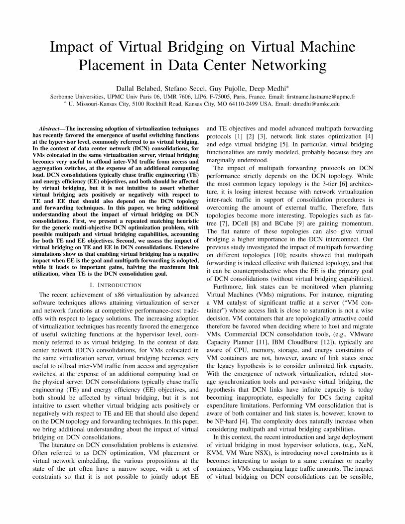
Alternative topologies have been proposed in recent years,as briefly mentioned in the introduction. Originally, the au-thors in [7] proposed a special instance of a Clos topologycalled “fat-tree” to interconnect commodity Ethernet switchesas k−ary fat-tree. As depicted in Fig. 1a, all switches areidentical and are organized on two layers: the core layer andthe pod layer. Generally, at the pod layer there are k pods,each one containing two layers of k
2 switches: edge switchesand aggregation switches. Each k-port switch in the lowerlayer (edge layer) is directly connected to k
2 hosts. Each ofthe remaining k
2 ports is connected to k2 of the k ports in
the aggregation layer. Concerning the core layer, there are(k2 )2 k-port core switches. Each core switch has one port
connected to each of the k pods. The ith port of any coreswitch is connected to the ith pod so that consecutive portsin the aggregation layer of each pod switch are connectedto the core switches on (k
2 ) strides. Fig. 1a shows a fat-tree example for k = 4. Another topology is BCube [9],a recursive architecture designed for shipping and container-based, modular data center. As depicted in Fig. 1b, the BCubesolution has server devices with multiple ports (typically nomore than four). Multiple layers of cheap commodity off-the-shelf mini-switches are used to connect those servers. ABCube0 is composed of n servers connected to an n-portswitch. A BCube1 is constructed from n BCube0s and n n-portswitches. More generally, a BCubek (k ≥ 1) is constructedfrom n BCubek−1s and nk n-port switches. For example, ina BCubek with n n-port switch, there are k + 1 levels ofswitches. Each server has k+ 1 ports, numbered from level-0to level-k. Hence, BCubek has N = nk+1 servers. Each levelhaving nk n-port switches. The construction of a BCubek isas follows. One numbers the n BCubek−1s from 0 to n − 1and the servers in each BCubek−1 from 0 to nk−1. Then oneconnects the level-k port of the ith server (i ∈ [0, nk−1]) in thejth BCubek−1 (j ∈ [0, n− 1]) to the jth port of the ith level-k switch. The BCube construction guarantees that switchesonly connect to servers and never connect directly to otherswitches, thus multipathing between switches is impossible. Itis worth noting that this kind of architecture requires virtualbridging in containers to operate. Fig. 1b shows an exampleof a BCube1, with n = 4.
Similarly to BCube, DCell [8] uses servers equipped withmultiple network ports and mini-switches to construct itsrecursive architecture. In DCell, a server is connected toseveral other servers and a mini-switch. Generally, a high-levelDCell is constructed from low-level DCells. The connectionbetween different DCell networks is typically done by usingvirtual bridging in containers. A DCellk (k ≥ 0) is usedto denote a level-k DCell. DCell0 is the building block toconstruct larger DCells. It has n servers and a mini-switch(n = 4 for DCell0 in Fig. 1c). All servers in DCell0 areconnected to the mini-switch.
In DCell1, each DCell0 is connected to all the other DCell0swith one link; the Fig. 1c shows a DCell1 example. DCell1has n + 1 = 5 DCell0s. DCell connects the 5 DCell0s asfollows. It assigns each server a 2-tuple [a1, a0], where a1and a0 are the level-1 and level-0 IDs, respectively. Thus a1and a0 take values from [0, 5) and [0, 4), respectively. Thentwo servers with 2-tuples [i, j − 1] and [j, i] are connectedwith a link for every i and every j > i.Each server has twolinks in DCell1. One connects to its mini-switch, and henceto other nodes within its own DCell0. The other connects to aserver in another DCell0. In DCell1, each DCell0, if treated asa virtual node, is fully connected with every other virtual nodeto form a complete graph. Moreover, since each DCell0 hasn inter-DCell0 links, a DCell1 can only have n + 1 DCell0s,as illustrated in Fig. 1c. A DCellk, is constructed in the sameway to the above DCell1 construction. The recursive DCellconstruction procedure [8] is more complex than the BCube
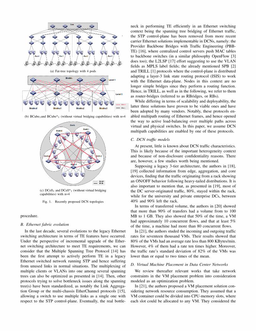
(a) Fat-tree topology with 4 pods
(b) BCube1and BCube*1 (without virtual bridging capabilities) with n=4
(c) DCell1 and DCell*1 (without virtual bridgingcapabilities) with n=4
Fig. 1. Recently proposed DCN topologies
procedure.
B. Ethernet fabric evolution
In the last decade, several evolutions to the legacy Ethernetswitching architecture in terms of TE features have occurred.Under the perspective of incremental upgrade of the Ether-net switching architecture to meet TE requirements, we canconsider that the Multiple Spanning Tree Protocol [14] hasbeen the first attempt to actively perform TE in a legacyEthernet switched network running STP and hence sufferingfrom unused links in normal situations. The multiplexing ofmultiple clients or VLANs into one among several spanningtrees can also be optimized as presented in [14]. Then, otherprotocols trying to solve bottleneck issues along the spanningtree(s) have been standardized, as notably the Link Aggrega-tion Group or the multi-chassis EtherChannel protocols [15],allowing a switch to use multiple links as a single one withrespect to the STP control-plane. Eventually, the real bottle-
neck in performing TE efficiently in an Ethernet switchingcontext being the spanning tree bridging of Ethernet traffic,the STP control-plane has been removed from more recentcarrier Ethernet solutions implementable in DCNs, namely: theProvider Backbone Bridges with Traffic Engineering (PBB-TE) [16], where centralized control servers push MAC tablesto backbone switches (in a similar philosophy OpenFlow [3]does too); the L2LSP [17] effort suggesting to use the VLANfields as MPLS label fields; the already mentioned SPB [2]and TRILL [1] protocols where the control-plane is distributedadapting a layer-3 link state routing protocol (ISIS) to workwith the Ethernet data-plane. Nodes in this context are nolonger simple bridges since they perform a routing function.Hence, in TRILL, as well as in the following, we refer to themas router-bridges (referred to as RBridges, or RBs).
While differing in terms of scalability and deployability, thelatter three solutions have proven to be viable ones and havebeen adopted by many vendors. Notably, these protocols en-abled multipath routing of Ethernet frames, and hence openedthe way to active load-balancing over multiple paths acrossvirtual and physical switches. In this paper, we assume DCNmultipath capabilities are enabled by one of these protocols.
C. DCN traffic models
At present, little is known about DCN traffic characteristics.This is likely because of the important heterogeneity contextand because of non-disclosure confidentiality reasons. Thereare, however, a few studies worth being mentioned.
Supposing a legacy 3-tier architecture, the authors in [18],[19] collected information from edge, aggregation, and coredevices, finding that the traffic originating from a rack showingan ON/OFF behavior following heavy-tailed distributions. It isalso important to mention that, as presented in [19], most ofthe DC server-originated traffic, 80%, stayed within the rack,while for the university and private enterprise DCs, between40% and 90% left the rack.
In terms of transferred volume, the authors in [20] showedthat more than 90% of transfers had a volume from to 100MB to 1 GB. They also showed that 50% of the time, a VMhad approximately 10 concurrent flows, and that at least 5%of the time, a machine had more than 80 concurrent flows.
In [21], the authors studed the incoming and outgoing trafficrates for seventeen thousand VMs. Their results showed that80% of the VMs had an average rate less than 800 KBytes/min.However, 4% of them had a rate ten times higher. Moreover,the traffic rate’s standard deviation of 82% of the VMs waslower than or equal to two times of the mean.
D. Virtual Machine Placement in Data Center Networks
We review thereafter relevant works that take networkconstraints in the VM placement problem into considerationmodeled as an optimization problem.
In [21], the authors proposed a VM placement solution con-sidering network resource consumption. They assumed that aVM container could be divided into CPU-memory slots, whereeach slot could be allocated to any VM. They considered the
number of VMs equal to the number of slots; if the number ofslots was higher than the number of VMs, they added dummyVMs (with no traffic), and did not affect the algorithm. Dueto a communication cost between slots, defined as the numberof forwarded frames among them, the objective was set asthe minimization of the average forwarding latency. They alsoassumed static single-path routing and focused on two trafficmodels. A dense one where each VM sent traffic to every VMsat an equal and constant rate, and a sparse Infrastructure asa Service (IaaS)-like one with isolated clusters so that onlyVMs in the same IaaS could communicate.
In [22], the authors consolidated VM placement consideringa non-deterministic estimation of bandwidth demands. Thebandwidth demand of VMs was set to follow normal dis-tributions. They formulated the consolidation in a StochasticBin Packing problem and introduced a new heuristic approachto resolve it. In [23], the authors considered network con-straints in addition to CPU and memory constraints in theVM placement problem. They defined a network-aware VMplacement optimization approach to allocate VM placementwhile satisfying predicted traffic patterns and reducing theworst case cut load ratio in order to support time-varyingtraffic. Interested by network cuts, they partitioned the set ofhosts into non-empty connected subsets, which are bottlenecksfor the traffic demand between VMs placed in different sidesof the cut.
In [24], the authors revisit the virtual embedding problem bydistinguishing between server and bridge nodes with respectto the common formulation. They proposed an iterative 3-stepheuristic: during the first step an arbitrary VM mapping wasdone; the second step mapped virtual bridges to bridges nodes,and the third one mapped virtual links accordingly. If oneof these steps failed, the heuristic would come back to theprevious one until a solution was found. The quality of thesolution seemed dependent on the first step, the other stepsjust minimized the impact of the previous step. Further, theremay have been a scaling problem due to the uncontrollablebacktracking. More generally, virtual embedding approachesin the literature often discarded specificities of the networkcontrol-plane such as the routing protocol and TE capabilities.
In [25], the authors optimized jobs placement whereeach job required a number of VMs; the objective functionminimized the network and the node costs. The authors didnot handle the link capacity constraints, and did not considermultipath forwarding capabilities instead multipath routingwith one single egress path. In [26], the authors minimizethe power energy consumption of activated servers, bridgesand links, to maximize the global energy saving. The authorsconverted the VM placement problems into a routing problem,and so they addressed the network and server optimizationproblem as a single one. So, there was no trade-off betweenthe network-side and server-side optimization objective.
Some of these studies ignored link capacity constraints,others excluded dynamic routing as in [21], or just consideredthe traffic volume to reduce the number of containers asin [22], or just the network resources as in [21] and [23],
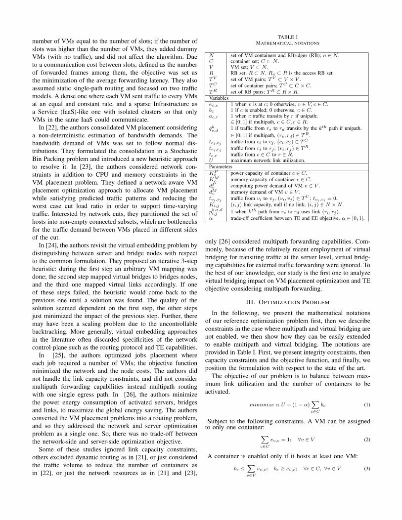
TABLE IMATHEMATICAL NOTATIONS
N set of VM containers and RBridges (RB); n ∈ N .C container set; C ⊂ N .V VM set; V ⊂ N .R RB set; R ⊂ N . Ra ⊂ R is the access RB set.TV set of VM pairs; TV ⊂ V × V .TC set of container pairs; TC ⊂ C × C.TR set of RB pairs; TR ⊂ R×R.Variablesev,c 1 when v is at c; 0 otherwise, v ∈ V, c ∈ C.bc 1 if c is enabled; 0 otherwise, c ∈ C.ac,r 1 when c traffic transits by r if unipath;
∈ [0, 1] if multipath, c ∈ C, r ∈ R.qks,d 1 if traffic from rs to rd transits by the kth path if unipath.
∈ [0, 1] if multipath, (rs, rd) ∈ TR.tci,cj traffic from ci to cj , (ci, cj) ∈ TC .tri,rj traffic from ri to rj ; (ri, rj) ∈ TR.tc,r traffic from c ∈ C to r ∈ R.U maximum network link utilization.ParametersKPc power capacity of container c ∈ C.
KMc memory capacity of container c ∈ C.
dPv computing power demand of VM v ∈ V .dMv memory demand of VM v ∈ V .tvi,vj traffic from vi to vj , (vi, vj) ∈ TV ; tvi,vi = 0.Ki,j (i, j) link capacity, null if no link; (i, j) ∈ N ×N .pk,s,di,j 1 when kth path from rs to rd uses link (ri, rj).α trade-off coefficient between TE and EE objective, α ∈ [0, 1].
only [26] considered multipath forwarding capabilities. Com-monly, because of the relatively recent employment of virtualbridging for transiting traffic at the server level, virtual bridg-ing capabilities for external traffic forwarding were ignored. Tothe best of our knowledge, our study is the first one to analyzevirtual bridging impact on VM placement optimization and TEobjective considering multipath forwarding.
III. OPTIMIZATION PROBLEM
In the following, we present the mathematical notationsof our reference optimization problem first, then we describeconstraints in the case where multipath and virtual bridging arenot enabled, we then show how they can be easily extendedto enable multipath and virtual bridging. The notations areprovided in Table I. First, we present integrity constraints, thencapacity constraints and the objective function, and finally, weposition the formulation with respect to the state of the art.
The objective of our problem is to balance between max-imum link utilization and the number of containers to beactivated.
minimize α U + (1− α)∑c∈C
bc (1)
Subject to the following constraints. A VM can be assignedto only one container:∑
c∈Cev,c = 1; ∀v ∈ V (2)
A container is enabled only if it hosts at least one VM:
bc ≤∑v∈V
ev,c; bc ≥ ev,c; ∀c ∈ C, ∀v ∈ V (3)
Each container is assigned to one RB:∑r∈R
ac,r = 1; ∀ c ∈ C (4)
Traffic between two access RBs is sent over a single path:∑k
qkrs,rd = 1 ∀(rs, rd) ∈ Ra ×Ra (5)
A VM is assigned to a container only if there are availableresidual computing resources:∑
v∈VdPv ev,c ≤ KP
c ;∑v∈V
dMv ev,c ≤ KMc ; ∀c ∈ C (6)
Container-RB traffic is less than the access link capacity:
tc,r ≤ Kc,r; ∀ c ∈ C ∀r ∈ R (7)
Inter-RB traffic is less than the aggregation-core link capacity:
∑rs,rd
∑k
trs,rdqkrs,rd
pk,rs,rdri,rj < U Kri,rj ∀(ri, rj) ∈ T
R (8)
Where:tc,r =
∑(vi,vj)∈TV
(tvi,vj + tvj ,vi ) evi,c ac,r; ∀r ∈ R, ∀c ∈ C
trs,rd =i 6=j∑
(ci,cj)∈TC
tci,cj aci,rs acj ,rd ; ∀(rs, rd) ∈ TR
tci,cj =∑
(vx,vy)∈TV
(tvx,vy + tvy,vx ) evx,ci evy,cj ; ∀ ci, cj ∈ C
We have a bi-criteria objective function that consists of theminimization of U , the maximum link utilization (TE goal),and the number of enabled containers (EE goal), weighted bythe α factor to assess the trade-off between the two goals andits impact on VM placement and DCN performance.
1) Enabling multipath capabilities: Multipath forwardingbetween containers and RBs (in the place of LAG, linkbonding, or similar approaches) can simply be enabled bydeclaring ac,r as a non-negative real variable instead of abinary variable. Hence, (4) becomes an integrity constraint onthe sum of traffic ratios for each active container to its RBs.Similarly, a multipath between RBs can simply be enabledby declaring qks,d as a non-negative real variable instead of abinary variable. Hence, (5) becomes an integrity constraint onthe sum of traffic ratios for each pair of RBs to its used paths.
2) Enabling virtual bridging: Enabling virtual bridgingmeans that the container absorbs the function of a bridge(typically at the hypervisor level). This feature can be easilyincluded by transforming the variable ac,r in a parameter andextending the RB set including the container nodes. Giventhat virtual bridging consumes additional power and memory,(6) should be slightly changed so that such an additionalcomponent, as a function of the traffic load, is included.
The provided optimization model is an extension of thebaseline multi-commodity flow (MCF) problem for networkrouting with link capacity constraints [27], taking into account:peculiar data center networking constraints due to VM mobil-ity, VM container switching on and off, virtual bridging, andmultipath forwarding. In order to control the MCF complexitywhen handling TE and multipath parameters and variables, weadopted above the link-path formulation [27].
Given the elasticity related to VM migrations and multi-pathing, requiring double mapping between VMs and VMcontainers, and between VM containers and usable paths, ouroptimization problem defined by (2)-(1) even if comprehensiveand versatile (considering both unipath and multipath modes,with and without virtual bridging, and VM attachment con-straints) is a non-linear problem and cannot be linearized.Single mapping could be linearized but not double mapping.
IV. HEURISTIC APPROACH
Classically, mapping problems can be revisited as facilitylocation problems, and when capacity constraints need tobe verified as a function of the type of mapping, there aresimilarities with the capacitated facility location problem [28]and, in particular, with the single source facility locationproblem (SSFLP) [29], [30]. It is easy to derive that ourDCN optimization problem can be reduced to the SSFLPand hence is NP-hard. Recently, modeling an optical networkdimensioning problem as a facility location problem, the au-thors in [31] extended a primitive repeated matching heuristicdescribed in [29], [30] to solve the SSFLP and proved it canreach optimality gaps below 5% also for many instances of theproblem. A similar approach was later adopted for an opticalnetwork dimensioning approach, also providing outstandingperformance for very large instances as described in [31].
Motivated by those results, we redesigned the repeatedmatching heuristic to our DCN optimization problem. Nev-ertheless, the double mapping we have handle in our problemand the multiple capacity constraints to care about (at both linkand server sides) made this problem is much more difficultto solve and comparison to the optimum is not possibledifferently than in previous applications [29], [30], [31].
A. Reformulation of the optimization problem
Recall that DCN communications are between VMs that canbe hosted behind the same VM container or behind distantcontainers interconnected by a DCN path. Certainly, externalcommunications can be modeled introducing fictitious VMsand VM containers acting as egress point, from a functionalstandpoint. When multipath is enabled, multiple paths can beused, and when virtual bridging is enabled, a VM containercan transit external traffic if the topology supports it. Whencommunicating VMs are not colocated, inter-VM communi-cation should involve a pair of containers and at least a DCNpath between them.
Let a virtual node be designated by v, v ∈ V , and a VMcontainer node pair be designated by cp, cp ∈ TC , so that cp =(ci, cj), i.e., a container pair is composed of two containersci and cj). When ci = cj the container pair cp is said to berecursive. A subset of container node pairs is designated byDC so, DC ⊆ TC . Let the kth path from RB r1 to RB r2 bedesignated by rp = (r1, r2, k). A set of RB paths is designatedby DR so that DR ⊂ TR.
Definition IV.1. Kit φ
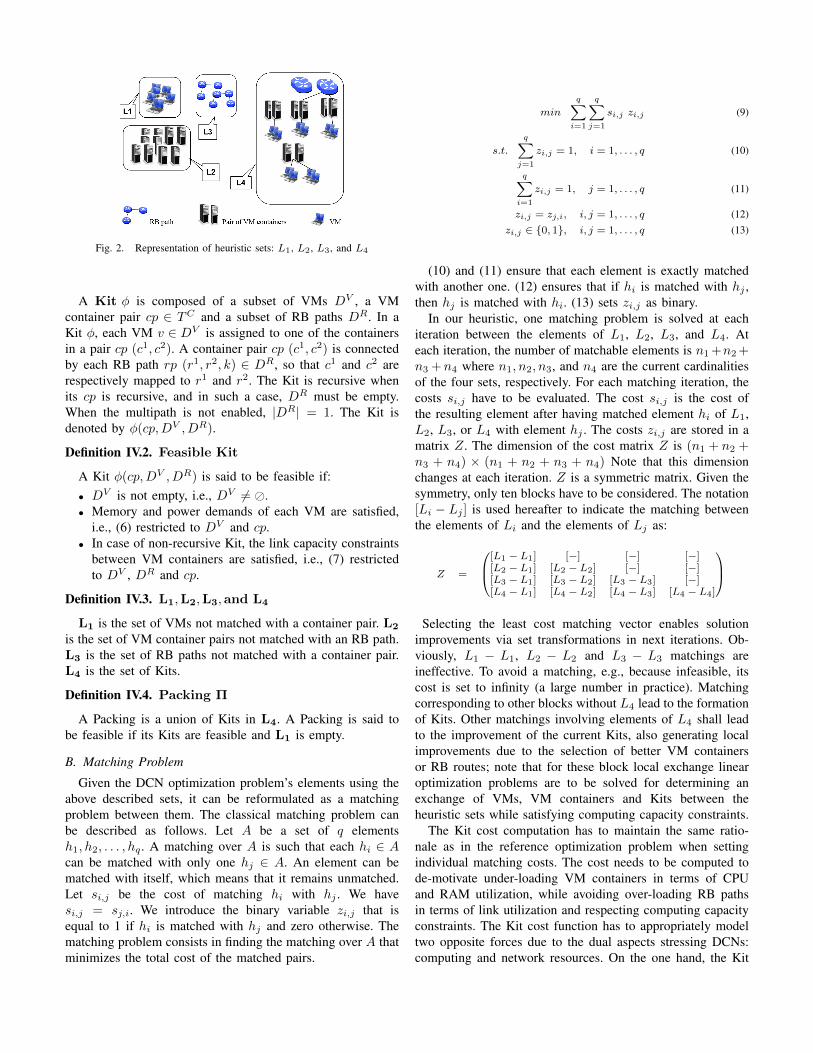
Fig. 2. Representation of heuristic sets: L1, L2, L3, and L4
A Kit φ is composed of a subset of VMs DV , a VMcontainer pair cp ∈ TC and a subset of RB paths DR. In aKit φ, each VM v ∈ DV is assigned to one of the containersin a pair cp (c1, c2). A container pair cp (c1, c2) is connectedby each RB path rp (r1, r2, k) ∈ DR, so that c1 and c2 arerespectively mapped to r1 and r2. The Kit is recursive whenits cp is recursive, and in such a case, DR must be empty.When the multipath is not enabled, |DR| = 1. The Kit isdenoted by φ(cp,DV , DR).
Definition IV.2. Feasible Kit
A Kit φ(cp,DV , DR) is said to be feasible if:• DV is not empty, i.e., DV 6= �.• Memory and power demands of each VM are satisfied,
i.e., (6) restricted to DV and cp.• In case of non-recursive Kit, the link capacity constraints
between VM containers are satisfied, i.e., (7) restrictedto DV , DR and cp.
Definition IV.3. L1,L2,L3,and L4
L1 is the set of VMs not matched with a container pair. L2
is the set of VM container pairs not matched with an RB path.L3 is the set of RB paths not matched with a container pair.L4 is the set of Kits.
Definition IV.4. Packing Π
A Packing is a union of Kits in L4. A Packing is said tobe feasible if its Kits are feasible and L1 is empty.
B. Matching Problem
Given the DCN optimization problem’s elements using theabove described sets, it can be reformulated as a matchingproblem between them. The classical matching problem canbe described as follows. Let A be a set of q elementsh1, h2, . . . , hq . A matching over A is such that each hi ∈ Acan be matched with only one hj ∈ A. An element can bematched with itself, which means that it remains unmatched.Let si,j be the cost of matching hi with hj . We havesi,j = sj,i. We introduce the binary variable zi,j that isequal to 1 if hi is matched with hj and zero otherwise. Thematching problem consists in finding the matching over A thatminimizes the total cost of the matched pairs.
min
q∑i=1
q∑j=1
si,j zi,j (9)
s.t.
q∑j=1
zi,j = 1, i = 1, . . . , q (10)
q∑i=1
zi,j = 1, j = 1, . . . , q (11)
zi,j = zj,i, i, j = 1, . . . , q (12)zi,j ∈ {0, 1}, i, j = 1, . . . , q (13)
(10) and (11) ensure that each element is exactly matchedwith another one. (12) ensures that if hi is matched with hj ,then hj is matched with hi. (13) sets zi,j as binary.
In our heuristic, one matching problem is solved at eachiteration between the elements of L1, L2, L3, and L4. Ateach iteration, the number of matchable elements is n1 +n2 +n3 +n4 where n1, n2, n3, and n4 are the current cardinalitiesof the four sets, respectively. For each matching iteration, thecosts si,j have to be evaluated. The cost si,j is the cost ofthe resulting element after having matched element hi of L1,L2, L3, or L4 with element hj . The costs zi,j are stored in amatrix Z. The dimension of the cost matrix Z is (n1 + n2 +n3 + n4) × (n1 + n2 + n3 + n4) Note that this dimensionchanges at each iteration. Z is a symmetric matrix. Given thesymmetry, only ten blocks have to be considered. The notation[Li − Lj ] is used hereafter to indicate the matching betweenthe elements of Li and the elements of Lj as:
Z =
[L1 − L1] [−] [−] [−][L2 − L1] [L2 − L2] [−] [−][L3 − L1] [L3 − L2] [L3 − L3] [−][L4 − L1] [L4 − L2] [L4 − L3] [L4 − L4]
Selecting the least cost matching vector enables solutionimprovements via set transformations in next iterations. Ob-viously, L1 − L1, L2 − L2 and L3 − L3 matchings areineffective. To avoid a matching, e.g., because infeasible, itscost is set to infinity (a large number in practice). Matchingcorresponding to other blocks without L4 lead to the formationof Kits. Other matchings involving elements of L4 shall leadto the improvement of the current Kits, also generating localimprovements due to the selection of better VM containersor RB routes; note that for these block local exchange linearoptimization problems are to be solved for determining anexchange of VMs, VM containers and Kits between theheuristic sets while satisfying computing capacity constraints.
The Kit cost computation has to maintain the same ratio-nale as in the reference optimization problem when settingindividual matching costs. The cost needs to be computed tode-motivate under-loading VM containers in terms of CPUand RAM utilization, while avoiding over-loading RB pathsin terms of link utilization and respecting computing capacityconstraints. The Kit cost function has to appropriately modeltwo opposite forces due to the dual aspects stressing DCNs:computing and network resources. On the one hand, the Kit
feasibility, in terms of link capacity constraints as describedabove does not need to be enforced during the repeatedmatching iterations, but to be motivated via the classicalTE costs inducing the minimization of the maximum linkutilization, and hence maximizing the minimum residual linkcapacity. On the other hand, residual computing capacities atthe VM container level should be considered as costs; it isnot suitable to have idle memory and CPU capacities whenreducing the VM container’s fixed energy consumptions is oneof the goals of the DC provider. The overall Kit cost is notmeant to represent a direct monetary cost, but it is such that therepeated matching promotes less expensive and more efficientKits. Therefore, to align with the objective function (1), andremembering that the cost of a Packing corresponds to the costof its Kits, we set the cost of a Kit φ(cp,DV , DR) as:
µ(φ) = (1− α)µE(φ) + αµTE(φ) (14)
Where α is the trade-off scaling factor between the EE andthe TE components, that are, respectively:
µE(φ) =∑ci∈cp
KPci∑
v∈DVi
dPv+
KMci∑
v∈DVi
dMv+ ΓTv
(15)
µTE(φ) = max(ni,nj)∈rp,rp∈φ
Uni,nj (Π) (16)
Where Tv represents the global traffic v sends and re-ceives, i.e., Tv =
∑v 6=v′
v′∈V tv,v′ ; Γ is the additional powerand memory, to take into account the impact of traffic toVM container’s CPU and memory consumption when virtualbridging is enabled (zero otherwise). Note that the computingcapacity constraints are indirectly enforced within the L4L4
matching cost computation. Uni,nj(Π) is the link utilization
of each link used by the current Packing Π solution, so thatthe maximum link utilization experienced by the Kit’s RBpaths can be minimized. In our heuristic, in order to linearlycompute the RB paths’ link utilization, the aggregation andcore links of RB paths are considered as congestion free,while access container-RB links are considered as prone tocongestion, Then generally adheres to the reality of mostDCNs today as access links are typically 1 G Ethernet linkswhile aggregation/core links reach the 10 Gbps and 40 Gbpsrates. This is a realistic approximation a acceptable in aheuristic approach, especially because it allows a significantdecrease in the heuristic’s time complexity.
C. Steps of the repeated matching heuristic
Due to the advantage of repeated matching between thedifferent sets as described above, we can get rid of thenon-linearities of the reference optimization problem with aheuristic approach that, based on the state of the art, is gearedto achieve low optimality gaps. Its steps are as follows.• Step 0: The algorithm starts with a degenerate Packing
with no Kits and all other sets full.• Step 1: A series of Packings is formed.• Step 1.1: The cost matrix Z is calculated for every block.
• Step 1.2: The least cost matching vector is selected.• Step 1.3: Go back to 1.1 for a new iteration unless the
Packing cost has not changed in the last three iterations.• Step 2: The heuristic stops, and in the case L1 is not
empty a local incremental solution is created assigningVMs in L1 to enabled and available VM containers or,if none, to new containers.
The least cost matching computation (Step 1.2) can be hardto solve optimally because of the symmetry constraint (12).In our heuristic, we decided to solve it in a suboptimal wayto lower the time complexity. We have implemented the algo-rithm in [32], based on the method of Engquist [33]. Its startingpoint is the solution vector of the matching problem withoutthe symmetry constraint (12) obtained with the algorithmdescribed in [34] that was chosen for its speed performance;its output is a symmetric solution matching vector.
Designing the matching costs in an efficient and rationalway, the Packing cost across iterations should be decreasing,monotonically starting by the moment when L1 gets empty;moreover, Step 2 should be reached and the heuristic con-verges, and L1 at the last step should be empty.
V. SIMULATION RESULTS
We implemented our heuristic using Matlab, we usedCPLEX for the computation of matching costs of some blocks.The adopted VM containers correspond to an Intel Xeon 5100server with 2 cores of 2.33GHz and 20GB RAM, able to host16 VMs. We study the virtual bridging impact on our virtualmachine placement model under two scenarios: when TE isthe primary goal and when EE is the primary goal. We alsoanalyze what happens when multipath forwarding is enabledat bridge level.
We executed our heuristic with the following DCN topolo-gies: 3-tier, fat-tree, BCube and DCell. We note that onlyBCube, and DCell had a server centric architecture so thattheir servers had to employ virtual bridging. However, forthe sake of comparison with 3-tier and fat-tree topologies, weincluded also variations of the conventional BCube and DCelltopologies in the analysis, while maintaining their flat nature.Instead of connecting BCube0 or DCell0 containers with thehigher level bridges, we connected BCube0 or DCell0 bridge,so they could work without virtual bridging; these variationswere marked as BCube* (Fig. 1b) and DCell* (Fig. 1c)).
In the simulations, all DCNs are loaded at 85% in terms ofcomputing and network capacity. Note that with all topologies,we allowed for a certain level of overbooking in the resourceallocation for the sake of algorithm fluidity especially atstarting and intermediate iterations. The capacity of the accesslink was set to 1Gbps. As not all VMs communicate to eachother in todays DCNs adopting network virtualization, butinstead traffic is segmented by IaaS management, we builtan IaaS-like traffic matrix as in [21], with clusters of up to 30VMs communicating with each-other and not communicatingwith other IaaS’s VMs. Within each IaaS, the traffic matrixwas built accordingly to the traffic distribution of [20]. We ran30 different instances with different traffic matrices for each
(a) Unipath (b) Multipath
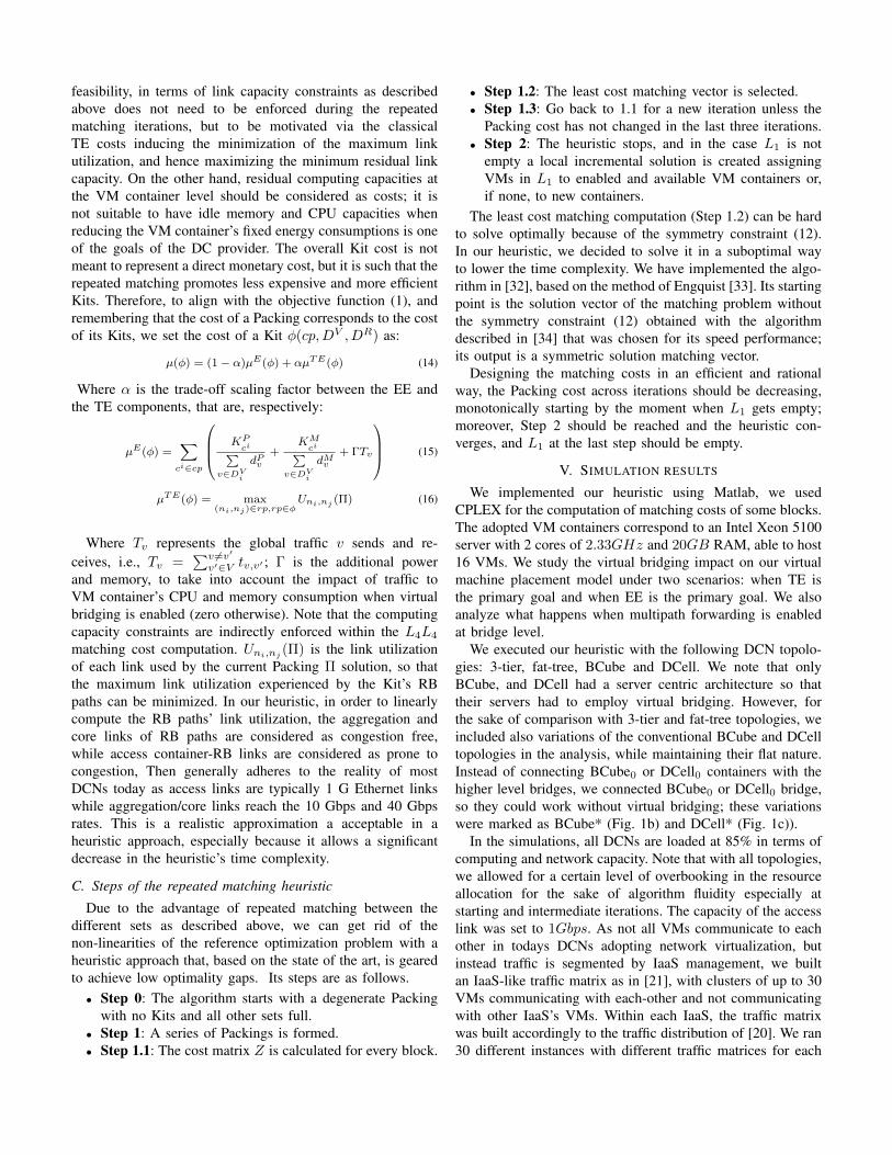
Fig. 3. Number of enabled VM containers (VB=Virtual Bridging)
case, and the results reported in the following were shown witha confidence interval of 95%. Our heuristic was fast (reachedconvergence roughly within a dozen of minutes per execution)and successfully reached a steady state, (i.e., three iterationslet to the same solution, characterized by a feasible Packingas previously described).
A. Virtual bridging impact under EE-oriented consolidations
Fig. 3 illustrates the results in terms of enabled VM con-tainers for different topologies when EE was the goal, (i.e.,α = 0 in the problem formulations). We report results forboth the cases when multipath forwarding was not enabled,(i.e., |DR| = 1 for all Kits) and the case where it is enabled.Observing the results we can assess the following:• the impact of virtual bridging in DCN consolidations
when the EE was the goal leads to negligible differencesin EE performance;
• with multipath forwarding, the use of virtual bridging wascounterproductive;
• the DCell topology showed better EE performance thanthe BCube, especially when multipath forwarding was en-abled. This can be explained by the higher path diversityat the DCell container;
• hierarchical topologies, fat-tree, and 3-layer, did show theoverall worst EE performance for single-path forwardingand better EE performance for multipath forwarding, withnegligible difference to each other.
All in all, the main outcome of this analysis is that enablingvirtual bridging does not bring any useful EE gain, and caneven worsen the EE performance, when the consolidation EEobjective is minimizing the number of enabled VM containers.
B. Virtual bridging impact under TE-oriented consolidations
As already mentioned, EE goals can be considered theopposite of TE goals. Chasing EE tends to minimize thenumber of enabled VM containers, yet no care is givento network link utilization. We rerun the experimentationssetting the traffic engineering goal as the DCN consolidationobjective, i.e., α = 1, considering singlepath and multipathforwarding, for the different topologies. Results are reportedin Fig. 4. Observing the results we can assess that:
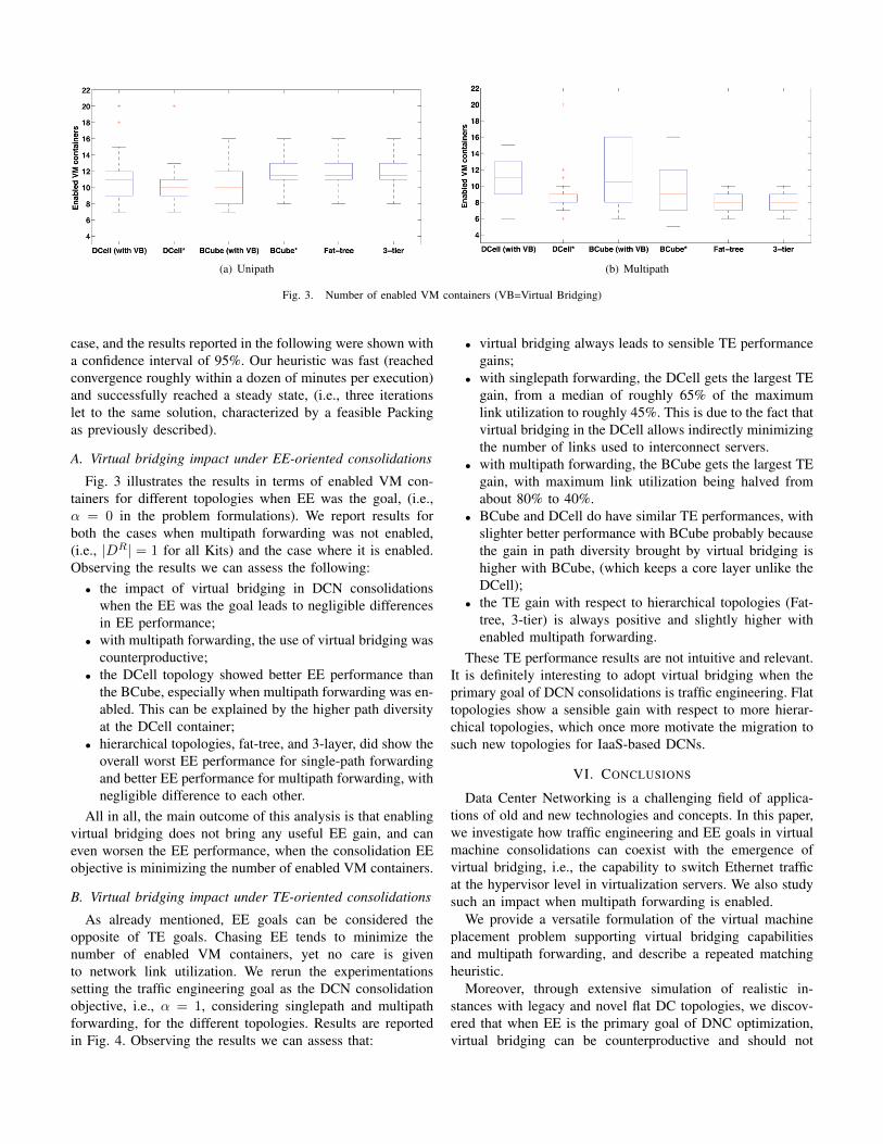
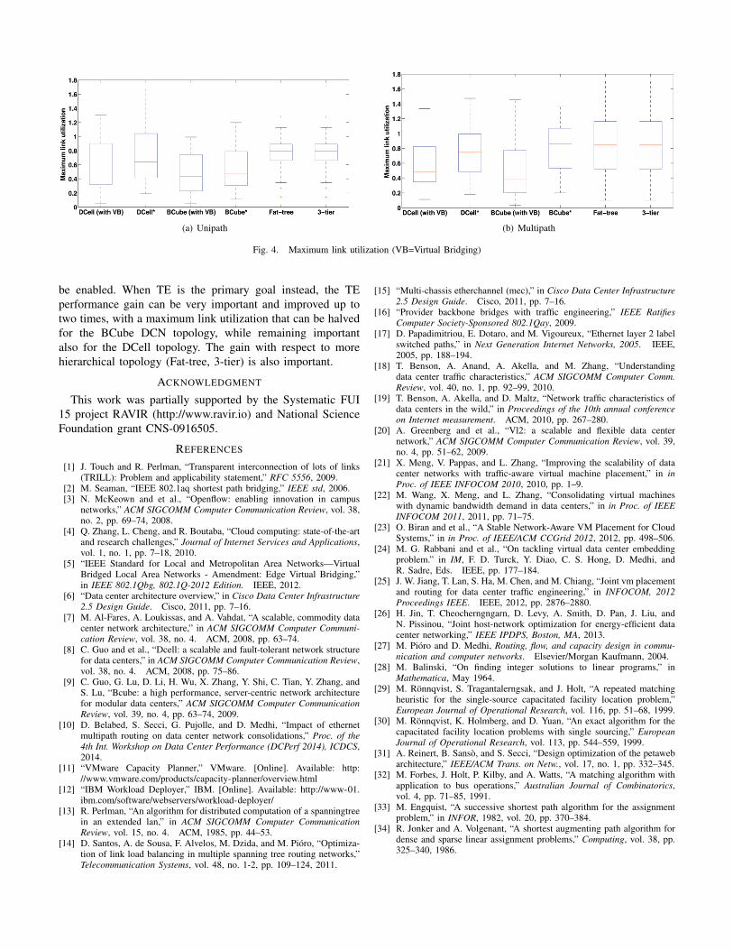
• virtual bridging always leads to sensible TE performancegains;
• with singlepath forwarding, the DCell gets the largest TEgain, from a median of roughly 65% of the maximumlink utilization to roughly 45%. This is due to the fact thatvirtual bridging in the DCell allows indirectly minimizingthe number of links used to interconnect servers.
• with multipath forwarding, the BCube gets the largest TEgain, with maximum link utilization being halved fromabout 80% to 40%.
• BCube and DCell do have similar TE performances, withslighter better performance with BCube probably becausethe gain in path diversity brought by virtual bridging ishigher with BCube, (which keeps a core layer unlike theDCell);
• the TE gain with respect to hierarchical topologies (Fat-tree, 3-tier) is always positive and slightly higher withenabled multipath forwarding.
These TE performance results are not intuitive and relevant.It is definitely interesting to adopt virtual bridging when theprimary goal of DCN consolidations is traffic engineering. Flattopologies show a sensible gain with respect to more hierar-chical topologies, which once more motivate the migration tosuch new topologies for IaaS-based DCNs.
VI. CONCLUSIONS
Data Center Networking is a challenging field of applica-tions of old and new technologies and concepts. In this paper,we investigate how traffic engineering and EE goals in virtualmachine consolidations can coexist with the emergence ofvirtual bridging, i.e., the capability to switch Ethernet trafficat the hypervisor level in virtualization servers. We also studysuch an impact when multipath forwarding is enabled.
We provide a versatile formulation of the virtual machineplacement problem supporting virtual bridging capabilitiesand multipath forwarding, and describe a repeated matchingheuristic.
Moreover, through extensive simulation of realistic in-stances with legacy and novel flat DC topologies, we discov-ered that when EE is the primary goal of DNC optimization,virtual bridging can be counterproductive and should not
(a) Unipath (b) Multipath
Fig. 4. Maximum link utilization (VB=Virtual Bridging)
be enabled. When TE is the primary goal instead, the TEperformance gain can be very important and improved up totwo times, with a maximum link utilization that can be halvedfor the BCube DCN topology, while remaining importantalso for the DCell topology. The gain with respect to morehierarchical topology (Fat-tree, 3-tier) is also important.
ACKNOWLEDGMENT
This work was partially supported by the Systematic FUI15 project RAVIR (http://www.ravir.io) and National ScienceFoundation grant CNS-0916505.
REFERENCES
[1] J. Touch and R. Perlman, “Transparent interconnection of lots of links(TRILL): Problem and applicability statement,” RFC 5556, 2009.
[2] M. Seaman, “IEEE 802.1aq shortest path bridging,” IEEE std, 2006.[3] N. McKeown and et al., “Openflow: enabling innovation in campus
networks,” ACM SIGCOMM Computer Communication Review, vol. 38,no. 2, pp. 69–74, 2008.
[4] Q. Zhang, L. Cheng, and R. Boutaba, “Cloud computing: state-of-the-artand research challenges,” Journal of Internet Services and Applications,vol. 1, no. 1, pp. 7–18, 2010.
[5] “IEEE Standard for Local and Metropolitan Area Networks—VirtualBridged Local Area Networks - Amendment: Edge Virtual Bridging,”in IEEE 802.1Qbg, 802.1Q-2012 Edition. IEEE, 2012.
[6] “Data center architecture overview,” in Cisco Data Center Infrastructure2.5 Design Guide. Cisco, 2011, pp. 7–16.
[7] M. Al-Fares, A. Loukissas, and A. Vahdat, “A scalable, commodity datacenter network architecture,” in ACM SIGCOMM Computer Communi-cation Review, vol. 38, no. 4. ACM, 2008, pp. 63–74.
[8] C. Guo and et al., “Dcell: a scalable and fault-tolerant network structurefor data centers,” in ACM SIGCOMM Computer Communication Review,vol. 38, no. 4. ACM, 2008, pp. 75–86.
[9] C. Guo, G. Lu, D. Li, H. Wu, X. Zhang, Y. Shi, C. Tian, Y. Zhang, andS. Lu, “Bcube: a high performance, server-centric network architecturefor modular data centers,” ACM SIGCOMM Computer CommunicationReview, vol. 39, no. 4, pp. 63–74, 2009.
[10] D. Belabed, S. Secci, G. Pujolle, and D. Medhi, “Impact of ethernetmultipath routing on data center network consolidations,” Proc. of the4th Int. Workshop on Data Center Performance (DCPerf 2014), ICDCS,2014.
[11] “VMware Capacity Planner,” VMware. [Online]. Available: http://www.vmware.com/products/capacity-planner/overview.html
[12] “IBM Workload Deployer,” IBM. [Online]. Available: http://www-01.ibm.com/software/webservers/workload-deployer/
[13] R. Perlman, “An algorithm for distributed computation of a spanningtreein an extended lan,” in ACM SIGCOMM Computer CommunicationReview, vol. 15, no. 4. ACM, 1985, pp. 44–53.
[14] D. Santos, A. de Sousa, F. Alvelos, M. Dzida, and M. Pioro, “Optimiza-tion of link load balancing in multiple spanning tree routing networks,”Telecommunication Systems, vol. 48, no. 1-2, pp. 109–124, 2011.
[15] “Multi-chassis etherchannel (mec),” in Cisco Data Center Infrastructure2.5 Design Guide. Cisco, 2011, pp. 7–16.
[16] “Provider backbone bridges with traffic engineering,” IEEE RatifiesComputer Society-Sponsored 802.1Qay, 2009.
[17] D. Papadimitriou, E. Dotaro, and M. Vigoureux, “Ethernet layer 2 labelswitched paths,” in Next Generation Internet Networks, 2005. IEEE,2005, pp. 188–194.
[18] T. Benson, A. Anand, A. Akella, and M. Zhang, “Understandingdata center traffic characteristics,” ACM SIGCOMM Computer Comm.Review, vol. 40, no. 1, pp. 92–99, 2010.
[19] T. Benson, A. Akella, and D. Maltz, “Network traffic characteristics ofdata centers in the wild,” in Proceedings of the 10th annual conferenceon Internet measurement. ACM, 2010, pp. 267–280.
[20] A. Greenberg and et al., “Vl2: a scalable and flexible data centernetwork,” ACM SIGCOMM Computer Communication Review, vol. 39,no. 4, pp. 51–62, 2009.
[21] X. Meng, V. Pappas, and L. Zhang, “Improving the scalability of datacenter networks with traffic-aware virtual machine placement,” in inProc. of IEEE INFOCOM 2010, 2010, pp. 1–9.
[22] M. Wang, X. Meng, and L. Zhang, “Consolidating virtual machineswith dynamic bandwidth demand in data centers,” in in Proc. of IEEEINFOCOM 2011, 2011, pp. 71–75.
[23] O. Biran and et al., “A Stable Network-Aware VM Placement for CloudSystems,” in in Proc. of IEEE/ACM CCGrid 2012, 2012, pp. 498–506.
[24] M. G. Rabbani and et al., “On tackling virtual data center embeddingproblem.” in IM, F. D. Turck, Y. Diao, C. S. Hong, D. Medhi, andR. Sadre, Eds. IEEE, pp. 177–184.
[25] J. W. Jiang, T. Lan, S. Ha, M. Chen, and M. Chiang, “Joint vm placementand routing for data center traffic engineering,” in INFOCOM, 2012Proceedings IEEE. IEEE, 2012, pp. 2876–2880.
[26] H. Jin, T. Cheocherngngarn, D. Levy, A. Smith, D. Pan, J. Liu, andN. Pissinou, “Joint host-network optimization for energy-efficient datacenter networking,” IEEE IPDPS, Boston, MA, 2013.
[27] M. Pioro and D. Medhi, Routing, flow, and capacity design in commu-nication and computer networks. Elsevier/Morgan Kaufmann, 2004.
[28] M. Balinski, “On finding integer solutions to linear programs,” inMathematica, May 1964.
[29] M. Ronnqvist, S. Tragantalerngsak, and J. Holt, “A repeated matchingheuristic for the single-source capacitated facility location problem,”European Journal of Operational Research, vol. 116, pp. 51–68, 1999.
[30] M. Ronnqvist, K. Holmberg, and D. Yuan, “An exact algorithm for thecapacitated facility location problems with single sourcing,” EuropeanJournal of Operational Research, vol. 113, pp. 544–559, 1999.
[31] A. Reinert, B. Sanso, and S. Secci, “Design optimization of the petawebarchitecture,” IEEE/ACM Trans. on Netw., vol. 17, no. 1, pp. 332–345.
[32] M. Forbes, J. Holt, P. Kilby, and A. Watts, “A matching algorithm withapplication to bus operations,” Australian Journal of Combinatorics,vol. 4, pp. 71–85, 1991.
[33] M. Engquist, “A successive shortest path algorithm for the assignmentproblem,” in INFOR, 1982, vol. 20, pp. 370–384.
[34] R. Jonker and A. Volgenant, “A shortest augmenting path algorithm fordense and sparse linear assignment problems,” Computing, vol. 38, pp.325–340, 1986.