impact of the number of coupling points on...
TRANSCRIPT

FACTA UNIVERSITATIS Series: Architecture and Civil Engineering Vol. 9, No 3, 2011, pp. 511 - 523 DOI: 10.2298/FUACE1103511T
IMPACT OF THE NUMBER OF COUPLING POINTS ON VALUES OF COMPOSITE BEAMS DEFORMATIONS
UDC 624.016:624.042.6:519.6=111
Mirsad Tarić1*, Emir Maslak2
1University of Priština, Faculty of Technical Sciences, Kosovska Mitrovica, Serbia 2University of Novi Pazar, Department for Technical and Technological Sciences,
Novi Pazar, Serbia * [email protected]
Abstract. Technological development, thanks to which high-performance materials were produced, allowed engineers to design elegant structures, which in the total load have smaller share of dead weight. All this gave an opportunity to bridge the large spans. Technological development is accompanied by the development of powerful computer software that is able to, in the phase of construction modelling, include many parameters. Thanks to that, designers have a better insight into how elements behave under load, and they are able to choose how to use material and exploit their good characteristics. Composite structures, formed by coupling of steel and concrete, rank among the modern structures. Their advantage lies in the fact that the steel part of the cross-section takes part in tensile stresses transfer, while the concrete part, because of its massiveness, takes part in compressive stress transfer. Redistribution of stresses in one composite cross-section depends on many factors. In this paper, using finite element method, the influence of number coupling points on the deformation of simply supported beam, with a composite cross-section was analysed. The span of the beam is 5m.
Key words: Composite beam, shear studs, deflection, finite element method.
INTRODUCTION
Modern approach in designing construction structures comprises constructions with as small cross-sections as possible. Smaller cross-section automatically implies smaller share of dead weight in total load. Development of technology and improvement of materials characteristics of which construction structures are made largely favour that aspiration.
Composite steel-concrete structures with their characteristics can respond to this re-quest. The advantage of composite structures is in the following:
Received December 02, 2011

M. TARIĆ, E. MASLAK 512
"by better distribution of materials, the characteristics of concrete and steel constructions are used in a much better way" [Mihajlović, 1989]. In that way, ten-sion stresses are entrusted to the steel element in the section, while concrete is re-sponsible for pressure stresses by its massiveness.
"in comparison to composite structures, it is easier to accept dynamic loads, be-cause dynamic characteristics of these structures are better (significantly higher ri-gidity of the structure, damping is higher etc.).
if we compare these structures to massive structures, it can be concluded that they are about two times lighter. Savings in funding can be significant. In addition, composite structures are, as a rule, made without scaffolds. Casing is much simpler because less jagged forms of cross-sections are applied." [Mihajlović, 1989]
Calculation of structures made of "kindred" materials (if something like that can be said for any material) generally is a complex job. This job becomes additionally complex when it comes to composite structures, because it is necessary to include mechanical characteristics of the material which composite section is made of into the calculation. In the beginning, calculation models of these structures, in order to be usable for daily engi-neering practice, were based on a series of assumptions, which can be found in [Đurić, 1963], [Izgradnja, 1972], [Lazić, 1988], and they served to simplify that model. In that way, calculation procedures adapted to everyday use were obtained, but the results depended on assumptions that the designer himself had to adopt. Incorrect assumptions have, most certainly, been reflected in the accuracy of results.
"On the other hand, mathematical modelling of object in theoretical-experimental analysis with the appearance of computer application programmes for CAA (Computer Aided Analysis) has gained in importance. In that way, by modelling we do not only im-ply the development of the geometry of structure of the beam (virtual digitalized model of the object), but we also tend to obtain an insight in as real as possible behaviour of the structure, by a set of activities from designer's standpoint. That is a description of ge-ometry, borderline conditions, characteristics of section, materials, load modelling, dis-cretization manner and form of finite elements, adoption of theoretical bases of calcula-tion etc. Therefore, it is aspired to higher reliabilities of the calculation of structure." [Miličić et all, 2008]
Numerous parameters influence stress-deformation condition of one composite sec-tion, as described in [Folić, Zenunović, 2009]. In these papers, the authors have examined the impact of the number of tension points on deformation of composite beam. As a starting point, we have used the research results of three composite beams on which con-centrated force in applied in the middle of the beam. In this experiment, concentrated force, which is applied in the middle of the beam, is increased up to the fracture. Calcula-tion of models in this paper is performed by applying the finite element method, in pro-gramme Sap2000 v6.11 Nonlinear, and in this model, the number of points in which AB plate is composited to steel beam was varied. In addition, comparative analysis was per-formed when the force is applied to AB plate and when the force is applied to steel beam directly.

Impact of the Number of Coupling Points on Values of Composite Beams Deformations 513
NUMERICAL EXAMPLE
Based on results of the studies of the three composite beams that were carried out in laboratory for constructions in INSA in Rennes, France [Aribert, Abdel Aziz, 1985], dia-grams of movement in the middle of a beam were made depending on the force. Studies included the impacts of lifting the plate depending on the space between the shear studs. Based on the curves given, it can be concluded that in the field of elastic work of material, the space between shear studs does not significantly affect the composite section load. These studies have served as a proof of a rapid convergence of solutions, even for rather rough discretization schemes (discretization network). Composite beams are static system simple beams of the range L=5m, with different distances between shear studs for tension as in Figure 1.
Steel beam is IPE 400, and reinforced plate is 800 mm wide, 100 mm thick and 5 m long. Modulus of elasticity for concrete plates is 2,4*107 kN/m2, and modulus of elasticity of steel is 2,14*108 kN/m2.
Force is applied in the middle of beam as shown in Figure III 1. Figure shows only a half of the beam (the other half is identical).
Fig. 1. Appearance of composite beams with cross-section
In case of all three beams, intensity of force that is applied in the middle of the range is increased up to the moment when deformations have become big even for small increment of force (fracture of the beam). Research results are given in the form of a diagram shown in Figure 2.

M. TARIĆ, E. MASLAK 514
Fig. 2. Diagram of movements in the middle of the beam depending on the size of force P
Models that are used for the analysis of composite beam by using discrete model based on the finite element method (FEM) are of the same dimensions as the above-mentioned beams. Based on theoretical studies with various discretization networks of the models described (which are presented in the following figures), it can be concluded that analysis of such composite beams gives rather realistic results.
In order to describe the work of a mathematical model (by using discrete model – FEM), two manners of applying the force to composite beam are used and the number of points in which reinforced plate is composited for steel beam is varied.
a) Force is applied on reinforced slab
Fig. 3. Cross-section of composite beam

Impact of the Number of Coupling Points on Values of Composite Beams Deformations 515
a1) results obtained in case when there is no coupling:
Fig. 4. Diagram "M" and "T" in AB-slab when there is no coupling in the model
All the impacts for this case of discretization are received by reinforced slab, because it is not compound with steel beam.
a2) results obtained for the case when plate and steel beam are composited only in two ending points:
Fig. 5. Coupling of steel beam only in end points
If reinforced slab is composited only in two end points of the beam, then compositing is performed only in those points and as a consequence of the rigidity of composite cross-section, only in the ends it comes to the cooperation of steel beam in the reception of bending moment. In the entire length of steel beam, there is a constant moment of bending as in figure III-5. As on the whole length of range there is no contact between AB slab and steel beam on mathematical model, the slab falls through steel beam. This phenomenon of 'falling through" reinforced slabs through steel beam is expressed only in case of schemes with a rough discretization network of composite structures. If we make a fine discretization network, this phenomenon disappears.

M. TARIĆ, E. MASLAK 516
a3) results obtained for the case when slab and steel beam are coupled in 3 points:
Fig. 6. Coupling of steel beam in 3 points
deflection in the middle of slab: v=0.00766m, moment in the middle of beam: Mbeams=152.28kNm, moment of composite part with slab: Mslab.=97.38kNm, stress in slab: σslab=-1.167kN/cm2.
For the case of coupling steel beam and reinforced slab in three points (two end points and the point in the middle of section), we obtain almost realistic picture of the work of composite beam.
a4) results obtained for the case when the slab and steel beam are coupled in 5 points:
Fig. 7. Coupling steel beam with AB slab in 5 points
deflection in the middle of slab: v=0.00761m, moment in middle of beam: Mbeams=150.54kNm, moment of composite part with slab: Mslab.=98.544kNm, stress in slab: σslab=-1.19kN/cm2.
Impact of the Number of Coupling Points on Values of Composite Beams Deformations 517
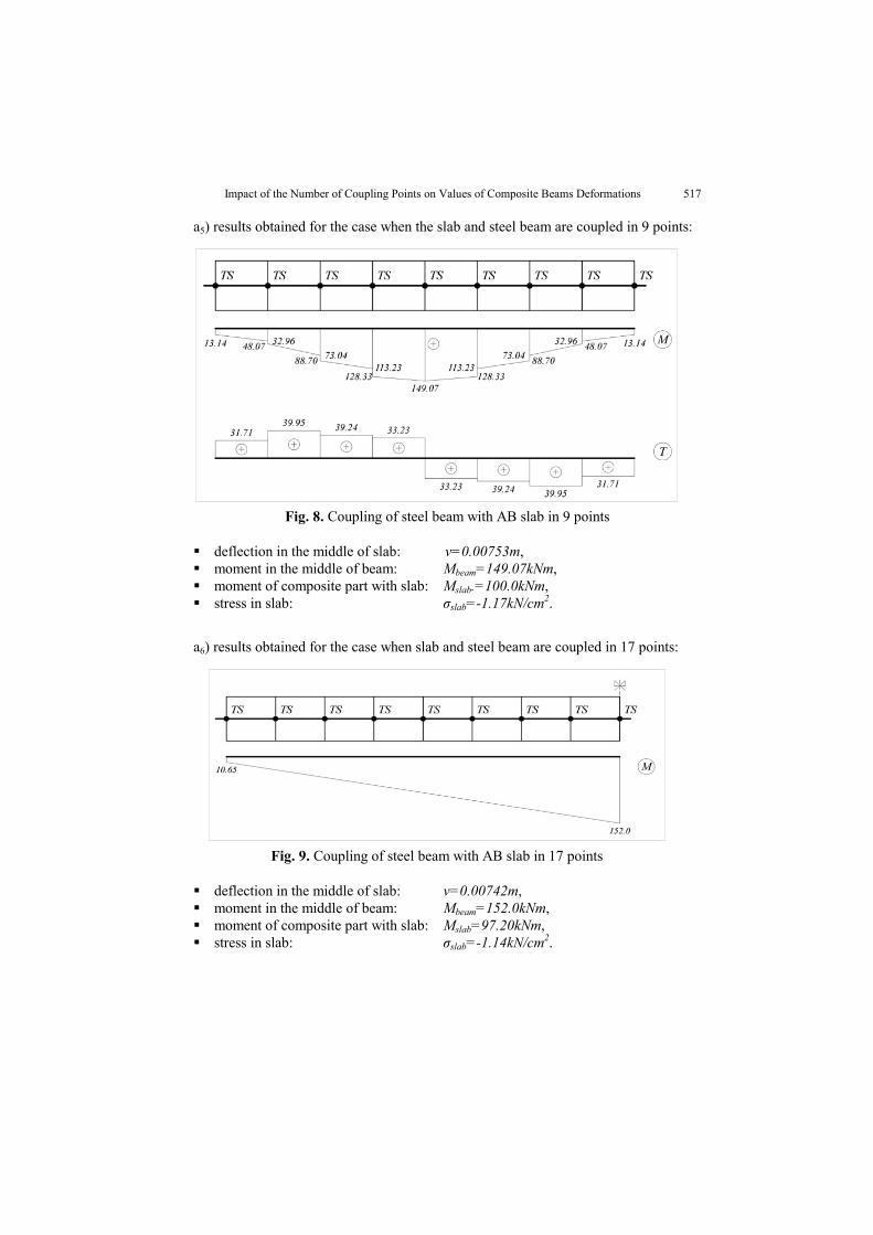
a5) results obtained for the case when the slab and steel beam are coupled in 9 points:
Fig. 8. Coupling of steel beam with AB slab in 9 points
deflection in the middle of slab: v=0.00753m, moment in the middle of beam: Mbeam=149.07kNm, moment of composite part with slab: Mslab.=100.0kNm, stress in slab: σslab=-1.17kN/cm2.
a6) results obtained for the case when slab and steel beam are coupled in 17 points:
Fig. 9. Coupling of steel beam with AB slab in 17 points
deflection in the middle of slab: v=0.00742m, moment in the middle of beam: Mbeam=152.0kNm, moment of composite part with slab: Mslab=97.20kNm, stress in slab: σslab=-1.14kN/cm2.

M. TARIĆ, E. MASLAK 518
a7) results obtained for the case when slab and steel beam are coupled in 33 points:
Fig. 10. Coupling of steel beam with AB slab in 17 points
deflection in the middle of slab: v=0.00736m, moment in the middle of beam: Mbeams=156.051kNm, moment of composite part with slab: Mslab.=93.80kNm, stress in slab: σslab=-1.09kN/cm2.
a8) results obtained for the case when slab and steel beam are coupled in 65 points:
Fig. 11. Coupling of steel beam with AB slab in 17 points
deflection in the middle of slab: v=0.00733m, moment in the middle of beam: Mbeams=159.79kNm, moment of composite part with slab: Mslab.=93.80kNm, stress in slab: σslab=-1.09kN/cm2.
b) Case when the force is applied to steel beam
Geometric characteristics of composite beam, static system, load – concentrated force (P = 200 kN operates in the middle of range) are the same as in previous cases. Mechanical characteristics of materials of which composite construction is made are also the same.

Impact of the Number of Coupling Points on Values of Composite Beams Deformations 519
b1) results obtained for the case when the slab and steel beam are coupled only in 2 end points:
Fig. 12. Coupling of steel beam with AB slab in two end points
deflection in the middle of slab: v=0.00926m, moment in the middle of beam: Mbeams=206.31kNm, moment of composite part with slab: Mslab.=43.69kNm,
b2) results obtained for the case when slab and steel beam are coupled in 3 points:
Fig. 13. Coupling of steel beam in 3 points
deflection in the middle of slab: v=0.00766m, moment in the middle of beam: Mbeams=154.09kNm, moment of composite part with slab: Mslab.=95.20kNm,
Although it is rather rough, discretization network gives rather realistic results of analysis. Results of analysis are almost the same as for the case a3. This tells us that no matter on which element of composite section (reinforced slab or steel beam) the force is applied, the same results are obtained, but only after three coupling points.

M. TARIĆ, E. MASLAK 520
b3) results obtained for the case when slab and steel beam are coupled in 5 points:
Fig. 14. Coupling of steel beam in 3 points
deflection in the middle of slab: v=0.00763m, moment in the middle of beam: Mbeams=150.59kNm, moment of composite part with slab: Mslab=99.10kNm,
b4) results obtained for the case when the slab and steel beam are coupled in 9 points:
Fig. 15. Coupling of steel beam in 9 points
deflection in the middle of slab: v=0.00754m, moment in the middle of beam: Mbeams=149.04kNm, moment of composite part with slab: Mslab.=100.91kNm, stress in slab: σslab=-1.18kN/cm2.

Impact of the Number of Coupling Points on Values of Composite Beams Deformations 521
b5) results obtained for the case when slab and steel beam are coupled in 17 points:
Fig. 16. Coupling of steel beam in 17 points
deflection in the middle of slab: v=0.00743m, moment in the middle of beam: Mbeams=152.0kNm, moment of composite part with slab: Mslab=97.20kNm, stress in slab: σslab=-1.17kN/cm2.
b6) results obtained for the case when slab and steel beam are coupled in 33 points:
Fig. 17. Coupling of steel beam in 33 points
deflection in the middle of slab: v=0.00736m, moment in the middle of beam: Mbeams=156.31kNm, moment of composite part with slab: Mslab.=93.20kNm, stress in slab: σslab=-1.12kN/cm2.

M. TARIĆ, E. MASLAK 522
b6) results obtained for the case when slab and steel beam are coupled in 65 points:
Fig. 18. Coupling of steel beam in 65 points
deflection in the middle of slab: v=0.00733m, moment in the middle of beam: Mbeams=159.79kNm, moment of composite part with slab: Mslab=91.80kNm, stress in slab: σslab=-1.10kN/cm2.
Values of deflection in the function of discretization of coupled beam are presented in the form of a diagram in Figure 19.
Fig. 19. Diagram of deflection convergence in the middle of beam depending
on the number of elements of steel beam

Impact of the Number of Coupling Points on Values of Composite Beams Deformations 523
ANALYSIS OF RESULTS AND CONCLUSIONS
By analyzing the obtained results of calculation of coupled beam with the help of finite element method, for the cases when the force was applied, whether on steel beam or AB slab, we reach the conclusion that with three coupling points, the results of analysis do not differ significantly. Mentioned studies tell us that in case of the analysis of coupled beams by discrete model based on FEM and with rather rough discretization schemes, we obtain rather realistic results that coincide with data on the curve given in Figure 2.
REFERENCES
1. V. Sbutega, "Sintetika I-IV", skripta, Beograd, 1970. 2. V. Sbutega, Nacrtna geometrija, Beograd, 1971. 3. V. Đurović, Nacrtna geometrija, Naučna knjiga, Beograd, 1963 4. E.H. Lockwood, A Book of Curves, Cambridge University Press. 1961, 5. Gino Loria and Fritz Schütte, Spezielle algebraische und transzendente ebene Kurven, B. G. Teubner, 1911 6. A. A. Savelov, Ravanske krivulje, Školska knjiga, Zagreb, 1979 7. L. Dovniković, Harmonija sfera, Matica srpska, Novi Sad, 1999 8. M. Marković, Nacrtna geometrija, Građevinski fakultet, Niš, 1998 9. P. Anagnosti, Nacrtna geometrija, Naučna knjiga, Beograd, 1981
10. В.О. Гордон, М.А. Семенцов – Огиевский, Курс начертательной геометрии, Наука, Москва, 1988. 11. Obradović R., Milojević Z.: Plane Section of Cone and Cylinder in Computer Geometry, Facta Universitatis,
Series Architecture and Civil Engineering, University of Niš, Vol.3, No 2, 2005, pp.195-207.
UTICAJ BROJA TAČAKA SPREZANJA NA VREDNOSTI DEFORMACIJA SPREGNUTIH NOSAČA
Mirsad Tarić, Emir Maslak
Tehnološki razvoj,zahvaljujući kojem su proizvedeni materijali visokih performansi, omogućio je projektovanje elegantnih konstrukcija koje u ukupnom opterećenju imaju sve manji udeo sopstvene težine. Sve to je dalo mogućnost premošćavanja velikih raspona. Tehnološki razvoj je praćen razvojem kompjuterskih programa, koji su u mogućnosti da u fazi projektovanja, uključe veliki broj parametara. Zahvaljujući tome konstrukter stiče bolji uvid u to kako se ponašaju elementi pod opterećenjem, pa je u mogućnosti da na najbolji način iskoristi dobre karakteristike upotrebljenih materijala. Konstrukcije nastale sprezanjem čelika i betona svrstavaju se u red savremenih konstrukcija. Njihova prednost ogleda se u tome što se čeličnom delu preseka poveravaju naponi zatezanja, dok je betonski deo, zbog svoje masivnosti, zadužen za napone pritiska. Kakva će biti preraspodela napona unutar jednog spregnutog preseka, zavisi od dosta činilaca. U ovom radu je, primenom metode konačnih elemenata, analiziran uticaj broja tačaka sprezanja na deformaciju jednog spregnutog nosača sistema proste grede i raspona 5m.
Ključne reči: spregnuti nosač, moždanici, ugib, metoda konačnih elemenata.