impact of the forces due to cliq ... - comsol multiphysics
TRANSCRIPT

Impact of the forces due to CLIQ
discharges on the MQXF Beam Screen
Marco Morrone, Cedric Garion TE-VSC-DLM

Content
The High Luminosity - LHC project
HL-LHC Beam screen design - Beam screen dimensions
- Conceptual specifications
Coupling-Loss Induced Quench (CLIQ)
Mechanical forces during a uniform magnetic field decay
Multiphysics model
- Quench protection scheme including CLIQ
Consequence of the CLIQ discharge on the beam screen design - Centring pin of the original beam screen design
- Centring pin of the new beam screen design
Conclusions
M. Morrone, C. Garion 2
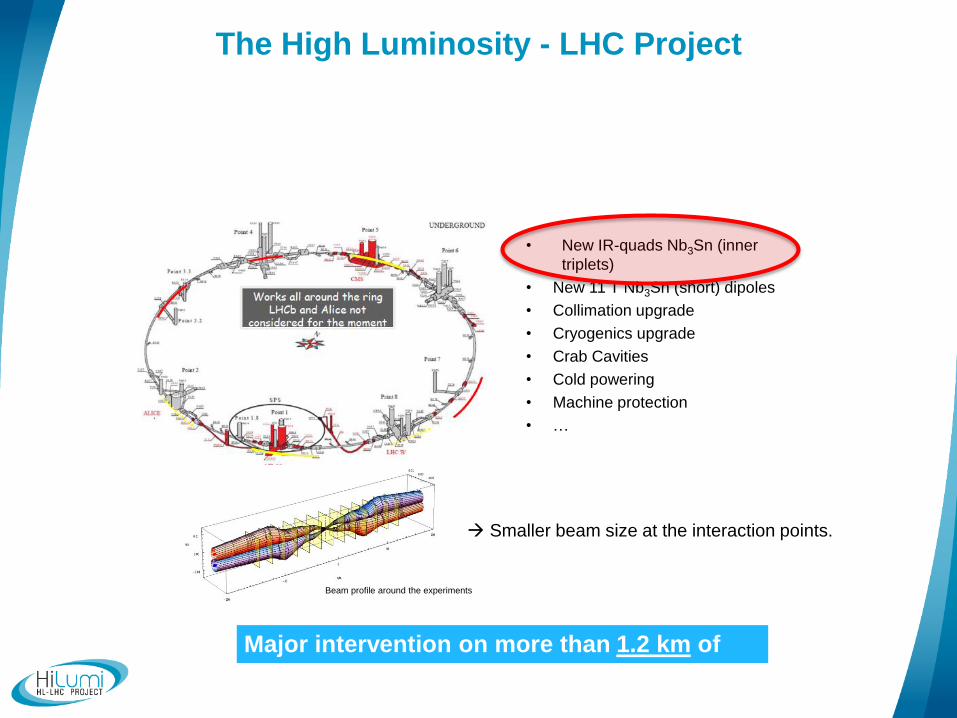
• New IR-quads Nb3Sn (inner
triplets)
• New 11 T Nb3Sn (short) dipoles
• Collimation upgrade
• Cryogenics upgrade
• Crab Cavities
• Cold powering
• Machine protection
• …
Major intervention on more than 1.2 km of
the LHC
Beam profile around the experiments
Smaller beam size at the interaction points.
25th November 2014 C. Garion
The High Luminosity - LHC Project
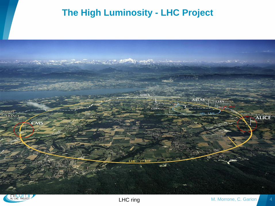
M. Morrone, C. Garion 4 LHC ring
The High Luminosity - LHC Project

Cold bore: separation
UHV/ superfluid helium
Cold mass
Beam
screen
Coils

HL-LHC beam screen design
M. Morrone, C. Garion 6
Cold bore (CB) at 1.9 K:
4 mm thick tube in 316LN
Tungsten alloy blocks:
• Chemical composition: 95% W, ~3.5% Ni, ~ 1.5% Cu
• mechanically connected to the beam screen tube:
positioned with pins and titanium elastic rings
• Heat load: 15-25 W/m
Cooling tubes:
• Outer Diameter: 10 or 16 mm
• Laser welded on the beam screen tube
Beam screen tube (BS) at ~ 50 K:
• Perforated tube (~2%) in High Mn High N stainless steel
(1740 l/s/m (H2 at 50K))
• Internal copper layer (80 mm) for impedance
• a-C coating (as a baseline) for e- cloud mitigation
• Laser treatments under investigation
Elastic supporting system:
Low heat leak to the cold bore tube at 1.9K
Ceramic ball with titanium spring
Thermal links:
• In copper
• Connected to the absorbers and the
cooling tubes or beam screen tube

Beam screen dimensions*
M. Morrone, C. Garion 7
Q1 Q2-Q3-D1
Q1 Q2 16 mm 6 mm
M. Morrone, C. Garion 7 7 Q1 Q2a Q2b Q3 CP D1
Triplet area layout
99.7 119.7
16 6
*The dimensions are given in mm
Cold Bore
Heat absorber
Octagonal pipe
Octagonal pipe
(stainless steel + copper)
1 0.08
Φ ext
16
1.5 mm
gap
4
14
4.7
14
4.7
Φ ext10

M. Morrone, C. Garion 8
Conceptual specification
“This component ensures the vacuum performance together with shielding the
cold mass from physics debris and screening the cold bore cryogenic system
from beam induced heating.
The shielded beam screen has to withstand the Lorentz forces induced by eddy
currents during a quench. 50 cycles at high field. (13th HL-LHC TC)
The temperature of the shielded beam screen must be actively controlled in a
given temperature range: 60-80 K. (Temperature window to be confirmed)
The system must be compatible with impedance performances.
The system must be compatible with the machine aperture.”

M. Morrone, C. Garion 9
Critical surface for Nb-Ti, showing the maximum allowed current
density as function of temperature and magnetic field.
Courtesy of L. Bortot
Coupling-Loss Induced Quench (CLIQ)
Magnet quench protection scheme
High-field magnets operate at currents as high
as 12 kA in superconducting state at 1.9 K.
The superconducting state is defined by:
- Critical temperature;
- Electric current density;
- Magnetic field.
Magnet quench: resistive transition of a
portion of the magnet
The superconducting state can be perturbed
for example by:
- Mechanical movements;
- AC losses;
- Beam losses. Release of energy = 7 MJ of energy stored
in each magnet that can melt more than 10
Kg of copper.
CLIQ protects the magnet by heating up it
from the inside in a uniform way.

Mechanical forces during a uniform magnetic field decay
Foucault currents are governed by Maxwell’s equation:
B(x,y,t)
rot E=-B/t
Ez(x,y,t) ~ B’
Ohm’s law: jz = Ez/r
Maxwell
B: magnetic field
E: electric field
j: current density
r: electrical resistivity
B(x,y,t)
jz Laplace’s (or
Lorentz’s) law
fv=jB
B(x,y,t)
jz
f fv ~ B’B
In a long structure, subjected to the magnetic field B:
j = E/r
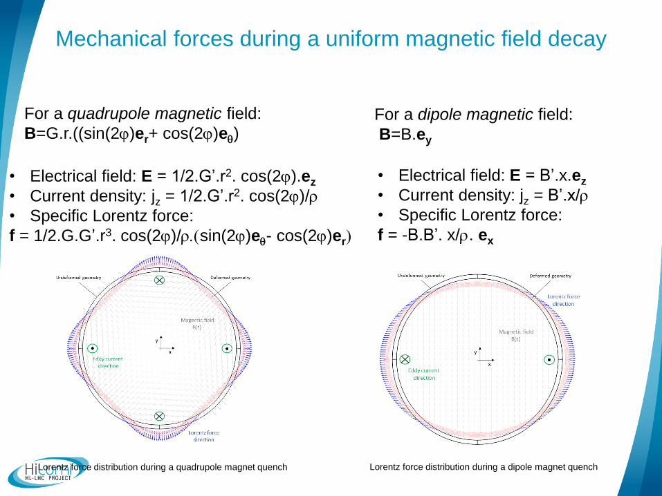
For a quadrupole magnetic field:
B=G.r.((sin(2j)er+ cos(2j)eq)
• Electrical field: E = 1/2.G’.r2. cos(2j).ez
• Current density: jz = 1/2.G’.r2. cos(2j)/r
• Specific Lorentz force:
f = 1/2.G.G’.r3. cos(2j)/r.(sin(2j)eq- cos(2j)er)
Lorentz force distribution during a quadrupole magnet quench
For a dipole magnetic field:
B=B.ey
• Electrical field: E = B’.x.ez
• Current density: jz = B’.x/r
• Specific Lorentz force:
f = -B.B’. x/r. ex
Lorentz force distribution during a dipole magnet quench
Mechanical forces during a uniform magnetic field decay

M. Morrone, C. Garion 12
Torque
𝑓 ∝𝐺𝐺
𝜌𝑟3
CLIQ currents evolution
Courtesy of Emmanuele Ravaioli
𝐺 has opposite sign in the first phase of the CLIQ discharge!
Therefore, opposite forces are expected in the same component.
Eddy currents
1 2 3
Ultimate currents_ I0=17800 A
1
1
Main direction of the equivalent forces.
The CLIQ discharge is due to a bank capacitor connected in
Parallel to the magnet coil. It introduces a current oscillation and,
Therefore, a magnetic field oscillation.

The model accounts for:
• Self-inductance;
• Two-way coupling (magnetic -
thermal);
13
Multiphysics model
Magnetic discharge
Induced currents
Temperature increase
due to heat losses
(Joule effect)
Mag
net
ic
Ther
mal
Two-way
coupling
Each Ω𝑚 domain can be controlled in current independently.
From the appropriate current input the quadrupole field can be approximated.

M. Morrone, C. Garion 14
The reduced field formulation cannot be used as the magnetic field decay is not uniform for each
pole. Therefore, the poles need to be taken into account. To this purpoe the coils are conveniently
approximated as permanent magnets and controlled in current to obtain an arbitrary magnetic field
profile. The CLIQ discharge can be then represented.
Roxie software used to field quality analysis at
CERN. The complex magnet coils need to be
considered.
COMSOL model used to approximate the
magnetic field generated through four
permanent magnets.
Multiphysics model

M. Morrone, C. Garion 15
Points Bx B’x1 ByB’y1 Bx B’x2 ByB’y2…
ROXIE 131.9574 157.3413 165.9134 123.4483
COMSOL 150.1908 183.7115 194.387 139.0675
average diff -0.226 %
Multiphysics model
Comparison of Bx,By given for 100 points around a
circumference of radius 58.85 mm.
Comparison of BxBx_dot and ByBy_dot given for 100 points
around a circumference of radius 58.85 mm.
BxBx_dot and ByBy_dot are good indicator
of the Lorentz forces magnitude

M. Morrone, C. Garion 16
Quench protection scheme including CLIQ
Integrated forces induced in the W block
1 2
1
2
Phase 1: Most critical!!
Torque
Tangential force
3
2 3
component Q1 Q2
Torque [N m/W block]
Tangential
force
[N/W block]
Torque
[N m/W block]
Tangential
force
[N/ W block]
Cold bore 253 3400 253 3400
Heat absorber 280 4200 148.5
2216
Octagonal pipe 81.5 1600 231 3800
Phase 3: Less severe than without CLIQ
E.g. Fy for the tungsten block: Q1NO CLIQ ~233.5 [N/mm] >
Q1CLIQ ~200.5 [N/mm]
Phase 2: Less severe than phase 1

Consequence of the CLIQ discharge
on the beam screen design
M. Morrone, C. Garion 17
Oval slot to allow different thermal contraction
at the W/ss interface (not welded!!)
0.5 mm gap
Pin welded through
Electric Resistance Welding (ERW)

M. Morrone, C. Garion 18
16 mm
Centring of the original beam screen design
CLIQ
NO CLIQ
4 mm

M. Morrone, C. Garion 19
4 mm
New pin concept
Centring of the proposed beam screen design
Less torque in comparison
with the straight pin
8 mm
12 mm F
4 mm

M. Morrone, C. Garion 20
Conclusions:
• An alternative solution of the beam screen based on new pins and heat
absorbers is proposed.
• The current design of the beam screen does not withstand the effects
of the CLIQ discharge without plastic deformations (Magnetic forces exported in an
other commercial FEM suite for the mechanical calculations);
• The COMSOL model based on a 2 way coupling between the magneto-thermal
physics has allowed to estimate the loads induced by CLIQ;

Thank you for you attention
M. Morrone, C. Garion 21