impact of incompletely filled groove on the integrity …
TRANSCRIPT

I. Dimić et al. Utjecaj grešaka u zavarenom spoju na integritet cijevnih lukova izloženih djelovanju unutarnjeg tlaka
ISSN 1330-3651 (Print), ISSN 1848-6339 (Online) UDC/UDK 621.643.2:[620.178.73:621.791.052]
EFFECT OF WELDED JOINT IMPERFECTION ON THE INTEGRITY OF PIPE ELBOWS SUBJECTED TO INTERNAL PRESSURE Ivana Dimić, Miodrag Arsić, Bojan Međo, Ana Stefanović, Vencislav Grabulov, Marko Rakin
Original scientific paper Since local defects reduce the load-carrying capacity and deformation ability of a piping system, an analysis is undertaken to quantify the influence of weld defects on integrity of the pipe elbows subjected to internal pressure. Incompletely filled groove is examined, because this type of defect was previously detected by ultrasonic measurement on the inner surface of the pipeline from a hydro-power plant. Three-dimensional finite element analysis is conducted using Abaqus software package. The influence of weld defect geometry (its depth, length and location) on the elbow integrity is determined. Additionally, decrease of load carrying capacity is determined for the case when a crack has initiated at the bottom of the defect. The influence of finite element type (hexahedral or tetrahedral) is examined. Keywords: elbow, finite element method, incompletely filled groove, pipe, structural integrity, welded joint Utjecaj grešaka u zavarenom spoju na integritet cijevnih lukova izloženih djelovanju unutarnjeg tlaka
Izvorni znanstvenu članak Imajući u vidu da lokalna oštećenja smanjuju nosivost i mogućnost deformiranja cjevovoda, analiziran je utjecaj grešaka u zavarenom spoju na integritet cijevnih lukova izloženih djelovanju unutarnjeg tlaka. Ispitivane su greške tipa neprovarenosti, jer su defekti ovog tipa prethodno otkriveni ultrazvučnim ispitivanjem na unutarnjoj površini cjevovoda u hidroelektrani. Trodimenzijska analiza metodom konačnih elemenata je urađena uporabom programskog paketa Abaqus. Određen je utjecaj geometrije defekta u zavarenom spoju (dubina, duljina i položaj) na integritet cijevnih lukova. Također je određen pad nosivosti u slučaju da postoji pukotina na dnu defekta. Ispitan je utjecaj tipa konačnih elemenata (rabljeni su elementi oblika heksaedra i tetraedra). Ključne riječi: cijev, cijevni luk, integritet konstrukcije, metoda konačnih elemenata, neprovarenost, zavareni spoj 1 Introduction Industrial pressure pipes, which are widely used in chemical, biochemical, pharmaceutical and other industries, can be regarded as pressure equipment of high risk. Pressure pipelines transport material is often inflammable, explosive, poisonous, strongly corrosive or hazardous in some other way Thus, their safety is a key point to ensure the safe exploitation of the entire production system. Detected defects, some of which can be classified as 'acceptable' during the control procedures, can often develop to the level that poses a threat to the construction safe service. Sometimes, cracks can even be initiated during the testing procedures [1]. Having in mind that reliability of pressurized equipment is crucial for efficient production and that a failure can often cause environmental hazard, a large amount of research activities has been conducted to determine the influence of various defects on the load carrying capacity (pre-cracks [2-6], corroded areas [7-11], welding defects [12], etc.). Also, influence of temperature has to be taken into account for high (or low) temperature applications, [13]. Pipe bends and elbows are used in various piping systems to allow modifications to isometric routings. They are also very important for the integrity of piping systems exposed to transient loading, because they absorb thermal expansions and seismic movements, as well as dissipate energy as a result of local plastic deformation. The elbow integrity assessment was the main subject of several recent studies; elbows without defects were examined in [14], while most of these studies were conducted with the aim to assess the influence of different defects (either crack-like or non crack-like) [15 ÷ 18]. Pipes and elbows in the process industry are often joined by circumferential welded joints. The defects are
inevitable, since joints are typically fabricated by manual arc welding, and the quality is difficult to control. Since local defects reduce the load-carrying capacity and deformation ability of the piping system, an analysis is undertaken to quantify the influence of weld defects on the integrity of the pipe elbows subjected to internal pressure. Incompletely filled groove is examined, because this type of defect was previously detected on the inner surface of the pipeline by ultrasonic measurement.
Figure 1 Pipe elbow with flange and welded joint with incompletely
filled groove
The aim of this study is to examine and analyze the effect of incompletely filled groove (Fig. 1) on the integrity of welded pipes and elbows in the system for regulation of the generator A6 in hydro-power plant "Đerdap I", Kladovo, Serbia. Welded pipes and elbows are subjected to the influence of internal pressure (4 MPa) of the turbine oil. The function of the regulation system
Tehnički vjesnik 20, 2(2013), 285-290 285

Effect of welded joint imperfection on the integrity of pipe elbows subjected to internal pressure I. Dimić et al.
A6, which consists of pipeline to supply oil to the turbine controller, is to open and close the blades and regulate the position of the blades and their speed. 2 Material
The pipelines of the regulation system A6 in hydropower plant "Đerdap I" have elbows with different geometries, Fig. 2. Pipes and elbows are made of steel А53 according to ASTM (Сталь 20 according to ГОСТ). Diameters and wall thickness are: ∅108 × 4 mm, ∅135 × 4 mm, ∅139 × 4 mm, ∅159 × 5 mm, ∅200 × 8 mm and ∅270 × 8 mm. The material properties are: Young’s modulus E = 210 GPa, Poisson’s ratio ν = 0,3, yield strength σY = 160 MPa. Also, the yield strength of the weld metal and the base material are very similar, i.e. the joint is evenmatched. Wall thicknesses were measured on all piping components (pipes, elbows, flanges). Measurements were carried using an ultrasonic device - Demeter (KRAUT-KRAMER DM-4), according to ISO 200.95.055. The measurements revealed the existence of incompletely filled grooves within the range of 5÷10 % of nominal (designed) thickness.
Figure 2 Examples of typical design and geometry of elbows in the
regulation system A6 in hydropower plant "Đerdap I"
Table 1 The necessary wall thickness of pipes and elbows in the regulation system A6 in hydropower plant "Đerdap I"
Geometry characteristics Necessary wall thickness
of the pipes smin / mm
Necessary wall thickness of the elbows
smin / mm
Outer pipe diameter D / mm
Nominal wall thickness of
the pipes so / mm
108 4 3,68 4,23 135 4 4,60 5,29 139 4 4,74 5,45 159 5 5,42 6,23 200 8 6,82 7,84 270 8 9,20 10,58 Necessary wall thickness of welded straight pipes in
the regulation system A6 is calculated according to the
applicable standard for pressure equipment SRPS M.E2.250 [19], while theory of elasticity is used for elbows. The results are given in Tab. 1; nominal thickness denotes the thickness of the pipe wall in the as-purchased condition. For the experimentally determined value of yield strength of welded joints, the necessary wall thickness of some pipes and elbows, calculated depending on the pipe diameter and nominal wall thickness, is not sufficient even if defects are not taken into account. Therefore, numerical assessment of elbow integrity under internal pressure is performed, on the example of the pipeline with the largest diameter (270 mm). Welded joint defects (which were previously observed by ultrasonic measurement) are taken into account, which will be explained in the following section. 3 Numerical analysis Three-dimensional finite element analysis is conducted using Abaqus software package, in order to determine the effect of local reduction of wall thickness on the integrity of pipes and elbows with weld defects. One half of each elbow is analysed due to the symmetry, and appropriate boundary conditions have been defined on the symmetry planes (Fig. 4). Loading is defined by prescribing the internal pressure, in accordance with the exploitation conditions. In addition to the elbows, a straight pipe with the same defect type is analysed, in order to compare the stress fields. When imposing restriction on the straight pipe, one pipe end is completely constrained, while the other end is free. Boundary conditions on the two ends of each elbow are modelled as fixed translation in the axial direction (Fig. 4). Concerning the finite element analysis, this study uses the C3D20R elements (20-node quadratic brick, reduced integration). Also, the C3D10MH elements (10-node quadratic tetrahedron, modified, hybrid, constant pressure) were used, in order to determine the influence of the type of elements on the results. Although some simplified FE models (see [20]) can be used for cylindrical components in some cases, full 3D analysis is conducted in this work, to adequately represent the stress/strain fields in the analysed geometries.
Figure 3 Model of a pipe with incomplete welding defect
The first finite element model consists of two welded
straight pipes. The inner pipe diameter is 270 mm and the wall thickness is 8 mm. The length of the model is 1000 mm, and one half of the model is analysed due to the symmetry, Fig. 3. As mentioned previously, this model is used for comparison of the stress state with that of the two
286 Technical Gazette 20, 2(2013), 285-290

I. Dimić et al. Utjecaj grešaka u zavarenom spoju na integritet cijevnih lukova izloženih djelovanju unutarnjeg tlaka
elbows. To improve the accuracy of the stress and strain fields, the mesh near the defect is finer in comparison with the region far away from the defect, as shown in Fig. 3.
The second and the third model are elbows with incomplete welding defects, Fig. 4. These elbows are denoted as A and B in the remainder of the text; the second elbow was formed by joining smaller pipe segments.
(a) (b)
Figure 4 Models of elbows with incomplete welding defect: elbow A (a) and elbow B (b) In this paper, models of pipes and elbows with different groove size (2×2, 2×1, 1×2, 1×1, 0,1×2 and 0,1×1 mm) were studied; these measures stand for the width and depth of a defect, Fig. 1. The range of defect sizes corresponds to the range detected by ultrasonic measurement. Plastic limit pressures of the pipe for all models were determined, and the results for 6 circumferential welding defects with different depths and widths are compared.
Figure 5 An example of LPF - arc length curve (LPF-Load
Proportionality Factor)
Limit pressure for elbows with defects is determined by elastic - perfectly plastic finite element analysis, [14, 15, 21, 22, 23]. To avoid problems associated with convergence in elastic - perfectly plastic calculation, the modified RIKS option within Abaqus was invoked. The corresponding fully plastic limit pressures are obtained from the RIKS factor (LPF - Load Proportionality Factor) from the FE analysis, as shown in Fig 5.
The RIKS method solves simultaneously for both load and displacement, using another quantity to measure the progress of the solution. This quantity is the "arc length" along the static equilibrium path in load-displacement space. Limit pressure was determined by multiplying the internal pressure (this value is set to 50 MPa for the analysed models) with the LPF obtained after elastic - perfectly plastic analysis.
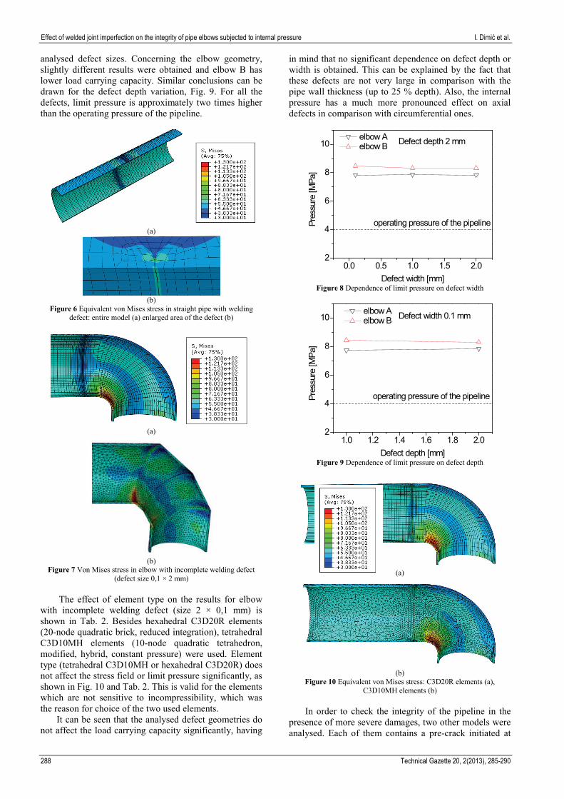
4 Results and discussion Stress and strain field concentration is analysed on the models of the straight pipe and both types of elbows. The results for the straight pipe are given in Fig. 6, and those for the two elbows are given in Fig. 7.
The three models shown in Figs. 6 and 7 have the same size of the welding defect, with depth 2 mm and width 0,1 mm. It can be seen that the stress concentration in the straight pipe is located only at the tip of the defect, while the elbows have another stress concentration location - on the inner side of the elbow (so-called intrados position, Fig. 13). The influence of curvature in pipeline also exists, because the two models of the elbows exhibit somewhat different stress state.
The limit pressure in the pipeline is determined by elastic - perfectly plastic finite element analysis, as explained in the previous section. The influence of the weld defect geometry on the integrity of the examined elbows is determined; dependence of limit pressure on the defect depth and width is established. Fig. 8 shows the dependence of the limit pressure on defect width. It can be seen that no significant variation is obtained for the
Tehnički vjesnik 20, 2(2013), 285-290 287
Effect of welded joint imperfection on the integrity of pipe elbows subjected to internal pressure I. Dimić et al.
analysed defect sizes. Concerning the elbow geometry, slightly different results were obtained and elbow B has lower load carrying capacity. Similar conclusions can be drawn for the defect depth variation, Fig. 9. For all the defects, limit pressure is approximately two times higher than the operating pressure of the pipeline.
(a)
(b)
Figure 6 Equivalent von Mises stress in straight pipe with welding defect: entire model (a) enlarged area of the defect (b)
(a)
(b)
Figure 7 Von Mises stress in elbow with incomplete welding defect (defect size 0,1 × 2 mm)
The effect of element type on the results for elbow with incomplete welding defect (size 2 × 0,1 mm) is shown in Tab. 2. Besides hexahedral C3D20R elements (20-node quadratic brick, reduced integration), tetrahedral C3D10MH elements (10-node quadratic tetrahedron, modified, hybrid, constant pressure) were used. Element type (tetrahedral C3D10MH or hexahedral C3D20R) does not affect the stress field or limit pressure significantly, as shown in Fig. 10 and Tab. 2. This is valid for the elements which are not sensitive to incompressibility, which was the reason for choice of the two used elements.
It can be seen that the analysed defect geometries do not affect the load carrying capacity significantly, having
in mind that no significant dependence on defect depth or width is obtained. This can be explained by the fact that these defects are not very large in comparison with the pipe wall thickness (up to 25 % depth). Also, the internal pressure has a much more pronounced effect on axial defects in comparison with circumferential ones.
0.0 0.5 1.0 1.5 2.02
4
6
8
10 Defect depth 2 mm
operating pressure of the pipeline
elbow A elbow B
Pres
sure
[MPa
]
Defect width [mm] Figure 8 Dependence of limit pressure on defect width
1.0 1.2 1.4 1.6 1.8 2.02
4
6
8
10 Defect width 0.1 mm
operating pressure of the pipeline
elbow A elbow B
Pres
sure
[MPa
]
Defect depth [mm] Figure 9 Dependence of limit pressure on defect depth
(a)
(b)
Figure 10 Equivalent von Mises stress: C3D20R elements (a), C3D10MH elements (b)
In order to check the integrity of the pipeline in the
presence of more severe damages, two other models were analysed. Each of them contains a pre-crack initiated at
288 Technical Gazette 20, 2(2013), 285-290

I. Dimić et al. Utjecaj grešaka u zavarenom spoju na integritet cijevnih lukova izloženih djelovanju unutarnjeg tlaka
the bottom of the 2 × 2 mm defect, Fig. 11. The limit pressure for the pre-cracked models is shown in Fig. 12; the pre-crack with length of 6 mm caused a decrease of limit pressure. Of course, if the crack growth initiation in such geometry is to be assessed, a fracture mechanics parameter (for elastic-plastic fracture mechanics, J integral or crack tip opening displacement) can be used.
Table 2 The effect of element type on the limit pressure Element type C3D20R C3D10MH
Limit pressure / MPa 7,82 7,81
Figure 11 Geometry of the circumferential pre-cracks
2 3 4 5 62
4
6
8
10
Crack depth [mm]
2x2 mm notch
Pres
sure
[MPa
]
operating pressure of the pipeline
elbow A
Figure 12 Dependence of limit pressure on the depth of a
circumferential crack
Figure 13 Partial circumferential defect positions
In addition to the models with a defect along the
entire circumference, models with a defect on a part of the circumference are also considered. For this analysis, the most severe damage is taken into account, i.e. the pre-crack with 6 mm depth (Fig. 11). The angle was varied from 90 to 360° (Fig. 13), and the dependence of the limit pressure on the crack circumferential angle is given in Fig. 14. It can be seen that decrease of the limit pressure occurs only for the angles exceeding 180°. Also, a small
difference between the cracks on the two sides (extrados and intrados, Fig. 13) is obtained.
60 120 180 240 300 3602
4
6
8
10 intrados side extrados side entire circumference
Crack circumferential angle [mm]
elbow A, crack depth 6 mm
Pres
sure
[MPa
]
operating pressure of the pipeline
Figure 14 Dependence of limit pressure on the circumferential angle of
a defect
It is very important to emphasize that the pressure loading of a pipeline is often accompanied by bending in exploitation, which is especially pronounced for the elbows. Such loading pattern causes the multiaxial stress state in the material; multiaxial loading and stress/strain state in structures are covered in [17, 18, 24]. Therefore, the analysis presented here is an initial point for examining the coupled influence of bending and internal pressure, which will be presented in another study. 5 Conclusions The impact of internal pressure on the pipes and elbows with incomplete welding defects is examined. The results are obtained for welding defects with different depths and widths; the defect size range is taken from the ultrasonic measurement performed on a pipeline in exploitation. 1) Different stress states were obtained for the two
analysed elbow geometries: the first was single-section elbow and the second was produced by welding the smaller pipe segments.
2) The defects discovered by ultrasonic measurement do not endanger the integrity of the examined pipes exposed to internal pressure, bearing in mind that similar limit pressures were obtained for most cases.
3) Finite element type (tetrahedral C3D10MH or hexahedral C3D20R) does not affect the results significantly, provided that the elements do not cause problems associated with incompressibility.
4) For the analysed geometries and loading, load carrying capacity of the joints can be significantly decreased only if a circumferential crack initiates at the bottom of a defect.
5) The influence of the circumferential angle of a defect, examined for the most severe case of a pre-crack, is not large for angles up to 180°.
6) In addition to the internal pressure, elbows are often exposed to bending loads in exploitation, which can significantly alter the presented results; therefore, the analysis of such combined loading cases will be presented elsewhere.
Tehnički vjesnik 20, 2(2013), 285-290 289

Effect of welded joint imperfection on the integrity of pipe elbows subjected to internal pressure I. Dimić et al.
Acknowledgements
The authors gratefully acknowledge the support from the Serbian Ministry of Education and Science under the projects TR 35002, ON174004 and E!5348. 6 References [1] Kurai, J.; Aleksić, B. Proof pressure test as a cause of crack
occurrence in pressurized equipment in service. // Structural Integrity and Life. 3, 2(2003), pp. 65-71.
[2] Chattopadhyay, J.; Dutta, B.K.; Kushwaha, H. S.; Roos, E.; Herter, K.-H. Load bearing capacity of flawed piping components - comparison of experiment with calculation. // International Journal of Pressure Vessels and Piping. 81, 7(2004), pp. 599-608.
[3] Pati, P. K.; Shrivastava, S. K.; Basu, S. Numerical analysis of crack initiation and growth in cylindrical geometries with an axial flaw. // International Journal of Fracture. 148, 4(2007), pp. 291-301.
[4] Gubeljak, N.; Vojvodić Tuma, J.; Šuštaršić, B.; Predan, J.; Oblak M. Assessment of the load-bearing capacity of a primary pipeline. // Engineering Fracture Mechanics. 74, 6(2007), pp. 995-1005.
[5] Berg, E.; Østby, E.; Thaulow, C.; Skallerud, B. Ultimate fracture capacity of pressurised pipes with defects - Comparisons of large scale testing and numerical simulations. // Engineering Fracture Mechanics. 75, 8(2008), pp. 2352-2366.
[6] Rakin, M.; Arsić, M.; Međo, B.; Šarkoćević, Ž.; Ivanović, I.; Sedmak, A. API J55 steel casing pipe with an initial surface crack under internal pressure - determination of fracture parameters. // Key Engineering Materials. 488-489, (2012), pp. 577-580.
[7] Choi, J. B.; Goo, B. K.; Kim, J. C.; Kim, Y. J.; Kim, W. S. Development of limit load solutions for corroded gas pipelines. // International Journal of Pressure Vessels and Piping. 80, 2(2003), pp. 121-128.
[8] Adib-Ramezani, H.; Jeong, J.; Pluvinage, G. Structural integrity evaluation of X52 gas pipes subjected to external corrosion defects using the SINTAP procedure. // International Journal of Pressure Vessels and Piping. 83, 6(2006), pp. 420-432.
[9] Chiodo, M.; Ruggieri, C. Failure assessments of corroded pipelines with axial defects using stress-based criteria: Numerical studies and verification analyses. // International Journal of Pressure Vessels and Piping. 86, 2,3(2009), pp. 164-176.
[10] Kozak, D.; Ivandić, Z.; Konjatić, P. Determination of the critical pressure for a hot-water pipe with a corrosion defect. // Materials and Technology. 44, 6(2010), pp. 385-390.
[11] Medjo, B.; Rakin, M.; Arsić, M.; Šarkoćević, Ž.; Zrilić, M.; Putić, S. Determination of the load carrying capacity of damaged pipes using local approach to fracture. // Materials Transactions – JIM. 53, 1(2012), pp. 185-190.
[12] Jin, Z. J.; Jiang, C. H.; Wan, X. P.; Chen, P.; Wang, X. F. Plastic limit load analysis for pressure pipe with incomplete welding defects based on the extended Net Section Collapse Criteria. // Journal of Zhejiang University-Science A (Applied Physics & Engineering). 11, 6(2010), pp. 440-448.
[13] Gaćeša, B.; Milošević-Mitić, V.; Maneski, T.; Kozak, D.; Sertić, J. Numerical and experimental strength analysis of fire-tube boiler construction. // Tehnički vjesnik - Technical Gazette. 18, 2(2011), pp. 237-242.
[14] Kim, Y. J.; Oh, C. S. Limit loads for pipe bends under combined pressure and in-plane bending based on finite element limit analysis. // International Journal of Pressure Vessels and Piping. 83, 2(2006), pp. 148-153.
[15] Kim, Y. J.; Song, T. K.; Kim, J. S.; Jin, T. E. Limit loads and approximate J estimates for axial through-wall cracked pipe bends. // International Journal of Fracture. 146, 4(2007), pp. 249-264.
[16] Hong, S. P.; Kim, J. H.; Kim, Y. J. Limit pressures of 90° elbows with circumferential surface cracks. // Engineering Fracture Mechanics. 76, 14(2009), pp. 2202-2216.
[17] Kim, J. W.; Na, M. G.; Park, C. Y. Effect of local wall thinning on the collapse behavior of pipe elbows subjected to a combined internal pressure and in-plane bending load. // Nuclear Engineering and Design. 238, 6(2008), pp. 1275-1285.
[18] Robertson, A.; Li, H.; Mackenzie, D. Plastic collapse of pipe bends under combined internal pressure and in-plane bending. // International Journal of Pressure Vessels and Piping. 82, 5(2005), pp. 407-416.
[19] SRPS M.E2.250 standard: Pressure vessels - Design of pressure vessels, 1991.
[20] Kovačević, D.; Budak, I.; Antić, A.; Kosec, B. Special finite elements: theoretical background and application. // Tehnički vjesnik - Technical Gazette. 18, 4(2011), pp. 649-655.
[21] Kim, Y. J.; Shim, D. J.; Huh, N. S.; Kim, Y. J. Plastic limit pressures for cracked pipes using finite element limit analyses. // International Journal of Pressure Vessels and Piping. 79, 5(2002), pp. 321-330.
[22] Huh, N. S.; Kim, Y. J.; Kim, Y. J. Limit load solutions for pipes with through-wall crack under single and combined loading based on finite element analyses. // Journal of Pressure Vessel Technology - Transactions of ASME. 129, 3(2007), pp. 468-473.
[23] Kim, Y. J.; Shim, D. J.; Nikbin, K.; Kim, Y. J.; Hwang, S. S.; Kim, J. S. Finite element based plastic limit loads for cylinders with part-through surface cracks under combined loading. // International Journal of Pressure Vessels and Piping. 80, 7-8(2003), pp. 527-540.
[24] Močilnik, V.; Gubeljak, N.; Predan, J.; Flašker, J. The influence of constant axial compression pre-stress on the fatigue failure of torsion loaded tube springs. // Engineering Fracture Mechanics. 77, 16(2010), pp. 3132-3142.
Authors’ addresses Ivana Dimić, PhD student Innovation Center of the Faculty of Technology and Metallurgy Karnegijeva 4, 11120 Belgrade, Serbia E-mail: [email protected] Miodrag Arsić, PhD Institute for Testing of Materials - IMS Bulevar vojvode Mišića 43, 11000 Belgrade, Serbia E-mail: [email protected] Bojan Medjo, PhD student University of Belgrade, Faculty of Technology and Metallurgy Karnegijeva 4, 11120 Belgrade, Serbia E-mail: [email protected] Ana Stefanović, MSc JAT Tehnika, Airport "Nikola Tesla" 11180 Belgrade, Serbia E-mail: [email protected] Vencislav Grabulov, PhD Institute for Testing of Materials - IMS, Bulevar vojvode Mišića 43, 11000 Belgrade, Serbia E-mail: [email protected] Prof. Marko Rakin, PhD University of Belgrade, Faculty of Technology and Metallurgy Karnegijeva 4, 11120 Belgrade, Serbia E-mail: [email protected]
290 Technical Gazette 20, 2(2013), 285-290