imi catalog 600c - meditronik.com.pl imi with associated logo, icp, swiveler, spindler, structcel,...
TRANSCRIPT

I N D U S T R I A L V I B R AT I O N S E N S O R S F O R C O N D I T I O N M O N I T O R I N G A N D P R E D I C T I V E M A I N T E N A N C E
P R O D U C T C A T A L O GP R O D U C T C A T A L O G
IMI Sensors Division — PCB Piezotronics, Inc.IMI Sensors Division — PCB Piezotronics, Inc.
In the interest of continuing product improvement, catalog specifications are subject to change without notice.Before machining tapped holes for installation, please request a copy of the item’s detailed installation drawing.
Registered trademarks of PCB Group, Inc. include:PCB, IMI with associated logo, ICP, Swiveler, Spindler, Structcel, and Modally Tuned.
All other trademarks are property of their respective owners.
IMI Sensors CatalogIMI-600C-0303
© 2003, PCB Group, Inc.PCB Quality is ISO-9001 certified
PCB is an EOE/AAP EmployerPrinted in USA
The IMI Sensors Division of PCB Piezotronics, Inc. is pleased to provide this catalog of our broadspectrum of standard products. Within this publication are sensors, accessories, and signal conditioning equipment, which have been specifically designed for industrial machinery vibrationmeasurements, condition based monitoring, process control, and predictive maintenance requirements.
In 1990, PCB Piezotronics Inc. formed the IMI Sensors Division to focus on the design effort ofrobust accelerometers for demanding industrial machinery monitoring applications. Today, IMI hasgrown to be a world leading manufacturer of industrial accelerometers with a product offering thatalso includes piezo-velocity sensors, 4-20 mA sensors and transmitters, accelerometers with on-board temperature sensors, portable vibration meters, and a full complement of signal conditioners, switching junction boxes, and accessories to support data collection and machinerydiagnostic applications. IMI’s customers encompass many industries.
Since 1967, PCB Piezotronics, Inc. has been a supplier of precision, piezoelectric sensors fordynamic acceleration, pressure and force measurement requirements. Recently, the addition ofcapacitive, piezoresistive, and strain-gage sensing technologies has propelled the company intoDC acceleration, static pressure, load, and torque measurement applications. Unmatched customer service, state-of-the-art manufacturing capabilities, and world-wide distribution havecontributed to the steady growth and success of PCB. Customers from industrial, governmental,commercial, educational, aerospace, automotive, medical, and R&D disciplines have all relied onPCB to deliver products and solutions for many demanding requirements.
The IMI Sensors Division of PCB Piezotronics, Inc. is an integrated team created to address thespecific sensor needs of those involved with the measurement of acceleration, motion, shock,and vibration under harsh factory conditions. Together, the Design, Engineering, Sales, CustomerService, and Marketing personnel within the IMI team draw upon the vast manufacturing resourceswithin PCB to continually provide new, more powerful, sensing solutions. Please do not hesitateto call upon us to assist with your measurement requirements and extend our guarantee ofTotal Customer Satisfaction.
Ford Motor Company Eastman Kodak CaterpillarProctor & Gamble EI DuPont Champion PaperValmet Praxair US NavyLTV Steel General Motors ALCOACampbell’s Soup USX Corporation Georgia Pacific

IMI SENSORS DIVISION TOLL-FREE � 800-959-4464
The IMI Sensors Division of PCB Piezotronics, Inc. offers a direct, toll-free telephone number for customer use. Feel free to call to discuss application requirements, request product literature,request price quotations, place orders, inquire about order status, expedite orders, troubleshoot equipment, or arrange forreturns. International customers are invited to call 716-684-0003.In addition, we can be reached by e-mail at [email protected]. Our faxnumber is: 716-684-3823. We look forward to hearing from you.
IMI offers to all customers, at no charge, 24-hour emergencyphone support. This service makes product and application sup-port available to our customers, day or night, seven days per week.To reach an IMI SensorLineSM customer service representative, call716-684-0003.
Products are featured on IMI’s web site — www.imi-sensors.com.The web site offers customers educational and technical information,as well as the latest product releases. Additionally, industrial sensors are featured with the ability to place an on-line order. Youmay also contact us via our general e-mail address at:[email protected].
PCB Piezotronics, Inc. is registered by the UnderwritersLaboratory, Inc. as an ISO 9001 facility and maintains a qualityassurance system dedicated to resolving any concern to ensureTotal Customer Satisfaction. PCB also conforms to the formerMIL-STD-45662 and MIL-Q-9858.
All IMI Sensors Division accelerometers are calibrated with fulltraceability to N.I.S.T. (National Institute of Standards &Technology) to ensure conformance to published specifications.Certificates of calibration are furnished that include actual meas-ured data. Calibration systems utilized are kept in full compliancewith ISO 9001 and ISO 10012-1 standards. Calibration methodsare accredited by A2LA to ISO 17025 standards.
IMI is committed to making every effort possible to accommodateall delivery requests. Our extensive in-house production capabili-ties permit us to manufacture most products to order in a timelyfashion. In the event that a specific model is unavailable in thetime frame that you need, we can usually offer a comparable unit,for sale or loan, to satisfy your urgent requirements. Many prod-ucts are available, from stock, for immediate shipment. Standardcable assemblies and accessory hardware items are alwaysstocked for immediate shipment and IMI never requires a minimum order amount. If you have urgent requirements, call afactory representative and every effort will be made to fulfill yourneeds.
IMI prides itself on being able to respond to customers’ needs.Heavy investment in machinery, capabilities, and personnel allow us to design, test, and manufacture products for specializedapplications. Please contact an IMI customer service representa-tive to discuss your special needs.
Many IMI products are designed, tested, and qualified to bear CEmarking in accordance with European Union EMC Directive.Products that have earned this qualification are so indicated bythe logo.
Instrumentation provided by IMI is covered by a limited warrantyagainst defective material and workmanship for a period of oneyear. Contact IMI for a complete statement of our warranty.
IMI has made a reasonable effort to ensure that the specificationscontained in this catalog were correct at the time of printing. Inthe interest of continuous product improvement, IMI reserves theright to change product specifications without notice at any time.Dimensions and specifications in this catalog may be approxi-mate and for reference purposes only. Before installing sensors,machining any surfaces, or tapping any holes, contact an IMIapplication specialist to obtain a current installation drawing andthe latest product specifications.
The IMI Sensors Division of PCB Piezotronics, Inc. guarantees Total Customer Satisfaction. If, at any time,for any reason, you are not completely satisfied with any IMI product, IMI will repair, replace, or exchange itat no charge. You may also choose, within the warranty period, to have your purchase price refunded.
IMI Sensors Division — PCB Piezotronics, Inc.Services and Qualifications
IMI Sensors Division — PCB Piezotronics, Inc.Services and Qualifications
i

24-HOUR SENSORLINESM 716-684-0003 • WEB SITE — www.imi-sensors.com
Numerical Model Number IndexNumerical Model Number Index
ii
A WORD ABOUT SPECIAL MODELS . . .
086C40 . . . . . . . . . . . . . . . . . . . . . . . .64,65086C41 . . . . . . . . . . . . . . . . . . . . . . . .64,65086C42 . . . . . . . . . . . . . . . . . . . . . . . .64,65121A2X . . . . . . . . . . . . . . . . . . . . . . . . . .68121A3X . . . . . . . . . . . . . . . . . . . . . . . . . .68401A04 . . . . . . . . . . . . . . . . . . . . . . . . . .96442 Series . . . . . . . . . . . . . . . . . . . . . . . .97443 Series . . . . . . . . . . . . . . . . . . . . . . . .97480 Series . . . . . . . . . . . . . . . . . . . . . . . .94481 Series . . . . . . . . . . . . . . . . . . . . . . . .98482 Series . . . . . . . . . . . . . . . . . . . . .95, 96484 Series . . . . . . . . . . . . . . . . . . . . . . . .95485B . . . . . . . . . . . . . . . . . . . . . . . . . . . .96488A02 . . . . . . . . . . . . . . . . . . . . . . . . . .94488A03 . . . . . . . . . . . . . . . . . . . . . . . . . .94492B . . . . . . . . . . . . . . . . . . . . . . . . . . . .96600A02 . . . . . . . . . . . . . . . . . . . . . . . . . .51600A03 . . . . . . . . . . . . . . . . . . . . . . . . . .51600A06 . . . . . . . . . . . . . . . . . . . . . . . . . .51600A07 . . . . . . . . . . . . . . . . . . . . . . . . . .51600A08 . . . . . . . . . . . . . . . . . . . . . . . . . .51600A09 . . . . . . . . . . . . . . . . . . . . . . . . . .51601AX1 . . . . . . . . . . . . . . . . . . . . . . .10,18602CX1 . . . . . . . . . . . . . . . . . . . . . . .10,18603CX1 . . . . . . . . . . . . . . . . . . . . . . . . .2,3604BX1 . . . . . . . . . . . . . . . . . . . . . . .38,39605BX1 . . . . . . . . . . . . . . . . . . . . . . .40,41606BX1 . . . . . . . . . . . . . . . . . . . . . . . . .8,9607AX1 . . . . . . . . . . . . . . . . . . . . . . . . .4,5608A11 . . . . . . . . . . . . . . . . . . . . . . . . . . .6612A01 . . . . . . . . . . . . . . . . . . . . .50,51,52621B40 . . . . . . . . . . . . . . . . . . . . . . . . . .24621B41 . . . . . . . . . . . . . . . . . . . . . . . . . .25621B51 . . . . . . . . . . . . . . . . . . . . . . . . . .26622AX1 . . . . . . . . . . . . . . . . . . . . . . .12,13623CX0 . . . . . . . . . . . . . . . . . . . . . . .20,21623CX1 . . . . . . . . . . . . . . . . . . . . . . .22,23624AX1 . . . . . . . . . . . . . . . . . . . . . . .16,18625BX0 . . . . . . . . . . . . . . . . . . . . . . .16,18625BX1 . . . . . . . . . . . . . . . . . . . . . . .14,15625BX2 . . . . . . . . . . . . . . . . . . . . . . .30,31626AX1 . . . . . . . . . . . . . . . . . . . . . . .32,33626AX2 . . . . . . . . . . . . . . . . . . . . . . . . . .36
626AX3 . . . . . . . . . . . . . . . . . . . . . . . . . .36626AX4 . . . . . . . . . . . . . . . . . . . . . . .34,35627AX1 . . . . . . . . . . . . . . . . . . . . . . .10,18628FX1 . . . . . . . . . . . . . . . . . . . . . . . .16,18629AX1 . . . . . . . . . . . . . . . . . . . . . . .42,43629AX2 . . . . . . . . . . . . . . . . . . . . . . .44,45629M05 . . . . . . . . . . . . . . . . . . . . . . . . . .46629M06 . . . . . . . . . . . . . . . . . . . . . . . . . .46631A80 . . . . . . . . . . . . . . . . . . . . . . . . . .27635A01 . . . . . . . . . . . . . . . . . . . . . . . . . .28640AX0 . . . . . . . . . . . . . . . . . . . . . . .54,58640AX1 . . . . . . . . . . . . . . . . . . . . . . .54,58640AX2 . . . . . . . . . . . . . . . . . . . . . . .54,58641AX0 . . . . . . . . . . . . . . . . . . . . . . .55,58641AX1 . . . . . . . . . . . . . . . . . . . . . . .55,58641AX2 . . . . . . . . . . . . . . . . . . . . . . .55,58645AX0 . . . . . . . . . . . . . . . . . . . . . . .56,58645AX1 . . . . . . . . . . . . . . . . . . . . . . .56,58645AX2 . . . . . . . . . . . . . . . . . . . . . . .56,58646AX0 . . . . . . . . . . . . . . . . . . . . . . .57,58646AX1 . . . . . . . . . . . . . . . . . . . . . . .57,58646AX2 . . . . . . . . . . . . . . . . . . . . . . .57,58650AX0 . . . . . . . . . . . . . . . . . . . . . . .60,62650AX5 . . . . . . . . . . . . . . . . . . . . . . .60,62650AX1 . . . . . . . . . . . . . . . . . . . . . . .61,62650AX4 . . . . . . . . . . . . . . . . . . . . . . .61,62671A01 . . . . . . . . . . . . . . . . . . . . . . . . . .68682A01 . . . . . . . . . . . . . . . . . . . . . . . . . .92682A02 . . . . . . . . . . . . . . . . . . . . . . . . . .92682A03 . . . . . . . . . . . . . . . . . . . . . . . . . .92682A04 . . . . . . . . . . . . . . . . . . . . . . . . . .93683A Series . . . . . . . . . . . . . . . . . . . . . .93687A01 . . . . . . . . . . . . . . . . . . . . . . . . . .90689B01 . . . . . . . . . . . . . . . . . . . . . . . . . .88689B11 . . . . . . . . . . . . . . . . . . . . . . . . . .89689B21 . . . . . . . . . . . . . . . . . . . . . . . . . .89691A2X . . . . . . . . . . . . . . . . . . . . . . .80,81691B33 . . . . . . . . . . . . . . . . . . . . . . . . . .78691B35 . . . . . . . . . . . . . . . . . . . . . . . . . .78691B40 . . . . . . . . . . . . . . . . . . . . . . . . . .75691B41 . . . . . . . . . . . . . . . . . . . . . . . . . .72691B42 . . . . . . . . . . . . . . . . . . . . . . . . . .73691B43 . . . . . . . . . . . . . . . . . . . . . . . . . .76
691B44 . . . . . . . . . . . . . . . . . . . . . . . . . .76691B45 . . . . . . . . . . . . . . . . . . . . . . . . . .77691B46 . . . . . . . . . . . . . . . . . . . . . . . . . .77691B47 . . . . . . . . . . . . . . . . . . . . . . . . . .74691A50 . . . . . . . . . . . . . . . . . . . . . . . . . .71691A51 . . . . . . . . . . . . . . . . . . . . . . . . . .70691A60 . . . . . . . . . . . . . . . . . . . . . . . . . .84691A61 . . . . . . . . . . . . . . . . . . . . . . . . . .85691A62 . . . . . . . . . . . . . . . . . . . . . . . . . .85691A70 . . . . . . . . . . . . . . . . . . . . . . . . . .84691A71 . . . . . . . . . . . . . . . . . . . . . . . . . .85691A72 . . . . . . . . . . . . . . . . . . . . . . . . . .85HT622A01 . . . . . . . . . . . . . . . . . . . . . . . .48HT623C01 . . . . . . . . . . . . . . . . . . . . . . . .48HT624A01 . . . . . . . . . . . . . . . . . . . . . . . .49HT625B01 . . . . . . . . . . . . . . . . . . . . . . . .48HT628F01 . . . . . . . . . . . . . . . . . . . . . . . .49VO622AX1 . . . . . . . . . . . . . . . . . . . . .17,18VO625AX1 . . . . . . . . . . . . . . . . . . . . .17,18VO626AX1 . . . . . . . . . . . . . . . . . . . . .17,18
Model Number . . . . . . .Page Model Number . . . . . . .Page Model Number . . . . . . .Page
The products in this IMI Sensors Division catalog reflect themost current technology, best performance, broad repre-sentation of popular features, and excellent value. Manyspecialty options and custom products are not included inthis publication.
Customers are encouraged to make known their specialrequests, particularly for products that have served faithfullyin the past. Consult an IMI factory application engineer forassistance in handling specialty or custom applications.
IMI SENSORS DIVISION TOLL-FREE � 800-959-4464
Table of ContentsTable of Contents
iii
TYPICAL INDUSTRIALVIBRATION SENSOR
APPLICATIONS• Aluminum Plants• Automotive Manufacturing• Balancing• Bearing Analysis & Diagnostics• Bearing Vibration Monitoring• Bridges and Civil Structures• Coal Processing• Cold Forming Operations• Concrete Processing Plants• Condition Based Monitoring• Compressors• Cooling Towers• Crushing Operations• Diagnostics of Machinery• Engines• Floor Vibration Monitoring• Food, Dairy & Beverage• Foundations• Gearbox Monitoring• Geological Exploration• Heavy Equipment & Machinery• Helicopters• Hull Vibration Monitoring• HVAC Equipment• Impact Measurements• Impulse Response• Machine Tools• Machinery Condition Monitoring• Machinery Frames• Machinery Mount Monitoring• Machinery Vibration Monitoring• Manufacturing• Mining• Modal Analysis• Motor Vibration• Off-Road Equipment• Paper Machinery Monitoring• Petrochemical• Pharmaceutical• Power Generation• Predictive Maintenance• Printing• Pulp and Paper• Pumps• Quality Control• Seismic Monitoring• Shipboard Machinery• Shock Measurements• Shredding Operations• Site Vibration Surveys• Slurry Pulsation Monitoring• Spindle Vibration & Imbalance• Squeak and Rattle Detection• Steel & Metals• Structure-Borne Noise• Structural Testing• Submersible Pumps• Transportation Equipment• Turbines• Turbomachinery• Underwater Pumps• Vibrating Feeders• Vibrating Screeners• Vibration Control• Vibration Isolation• Water Treatment Plants• Wastewater Treatment Plants
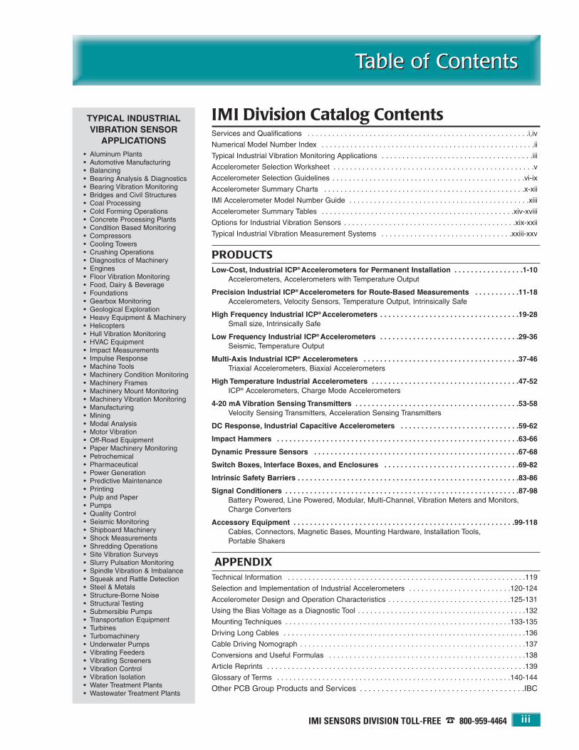
IMI Division Catalog ContentsServices and Qualifications . . . . . . . . . . . . . . . . . . . . . . . . . . . . . . . . . . . . . . . . . . . . . . . . . . . . . .i,iv
Numerical Model Number Index . . . . . . . . . . . . . . . . . . . . . . . . . . . . . . . . . . . . . . . . . . . . . . . . . . . .ii
Typical Industrial Vibration Monitoring Applications . . . . . . . . . . . . . . . . . . . . . . . . . . . . . . . . . . . . .iii
Accelerometer Selection Worksheet . . . . . . . . . . . . . . . . . . . . . . . . . . . . . . . . . . . . . . . . . . . . . . . . .v
Accelerometer Selection Guidelines . . . . . . . . . . . . . . . . . . . . . . . . . . . . . . . . . . . . . . . . . . . . . . .vi-ix
Accelerometer Summary Charts . . . . . . . . . . . . . . . . . . . . . . . . . . . . . . . . . . . . . . . . . . . . . . . . .x-xii
IMI Accelerometer Model Number Guide . . . . . . . . . . . . . . . . . . . . . . . . . . . . . . . . . . . . . . . . . . . .xiii
Accelerometer Summary Tables . . . . . . . . . . . . . . . . . . . . . . . . . . . . . . . . . . . . . . . . . . . . . . .xiv-xviii
Options for Industrial Vibration Sensors . . . . . . . . . . . . . . . . . . . . . . . . . . . . . . . . . . . . . . . . . .xix-xxii
Typical Industrial Vibration Measurement Systems . . . . . . . . . . . . . . . . . . . . . . . . . . . . . . . .xxiii-xxv
PRODUCTSLow-Cost, Industrial ICP® Accelerometers for Permanent Installation . . . . . . . . . . . . . . . . .1-10
Accelerometers, Accelerometers with Temperature Output
Precision Industrial ICP® Accelerometers for Route-Based Measurements . . . . . . . . . . .11-18Accelerometers, Velocity Sensors, Temperature Output, Intrinsically Safe
High Frequency Industrial ICP® Accelerometers . . . . . . . . . . . . . . . . . . . . . . . . . . . . . . . . . .19-28Small size, Intrinsically Safe
Low Frequency Industrial ICP® Accelerometers . . . . . . . . . . . . . . . . . . . . . . . . . . . . . . . . . .29-36Seismic, Temperature Output
Multi-Axis Industrial ICP® Accelerometers . . . . . . . . . . . . . . . . . . . . . . . . . . . . . . . . . . . . . .37-46Triaxial Accelerometers, Biaxial Accelerometers
High Temperature Industrial Accelerometers . . . . . . . . . . . . . . . . . . . . . . . . . . . . . . . . . . . .47-52ICP® Accelerometers, Charge Mode Accelerometers
4-20 mA Vibration Sensing Transmitters . . . . . . . . . . . . . . . . . . . . . . . . . . . . . . . . . . . . . . . .53-58Velocity Sensing Transmitters, Acceleration Sensing Transmitters
DC Response, Industrial Capacitive Accelerometers . . . . . . . . . . . . . . . . . . . . . . . . . . . . .59-62
Impact Hammers . . . . . . . . . . . . . . . . . . . . . . . . . . . . . . . . . . . . . . . . . . . . . . . . . . . . . . . . . . .63-66
Dynamic Pressure Sensors . . . . . . . . . . . . . . . . . . . . . . . . . . . . . . . . . . . . . . . . . . . . . . . . . .67-68
Switch Boxes, Interface Boxes, and Enclosures . . . . . . . . . . . . . . . . . . . . . . . . . . . . . . . . .69-82
Intrinsic Safety Barriers . . . . . . . . . . . . . . . . . . . . . . . . . . . . . . . . . . . . . . . . . . . . . . . . . . . . . .83-86
Signal Conditioners . . . . . . . . . . . . . . . . . . . . . . . . . . . . . . . . . . . . . . . . . . . . . . . . . . . . . . . . .87-98Battery Powered, Line Powered, Modular, Multi-Channel, Vibration Meters and Monitors, Charge Converters
Accessory Equipment . . . . . . . . . . . . . . . . . . . . . . . . . . . . . . . . . . . . . . . . . . . . . . . . . . . . . .99-118Cables, Connectors, Magnetic Bases, Mounting Hardware, Installation Tools,Portable Shakers
APPENDIXTechnical Information . . . . . . . . . . . . . . . . . . . . . . . . . . . . . . . . . . . . . . . . . . . . . . . . . . . . . . . . . .119
Selection and Implementation of Industrial Accelerometers . . . . . . . . . . . . . . . . . . . . . . . . .120-124
Accelerometer Design and Operation Characteristics . . . . . . . . . . . . . . . . . . . . . . . . . . . . . .125-131
Using the Bias Voltage as a Diagnostic Tool . . . . . . . . . . . . . . . . . . . . . . . . . . . . . . . . . . . . . . . . .132
Mounting Techniques . . . . . . . . . . . . . . . . . . . . . . . . . . . . . . . . . . . . . . . . . . . . . . . . . . . . . . .133-135
Driving Long Cables . . . . . . . . . . . . . . . . . . . . . . . . . . . . . . . . . . . . . . . . . . . . . . . . . . . . . . . . . . .136
Cable Driving Nomograph . . . . . . . . . . . . . . . . . . . . . . . . . . . . . . . . . . . . . . . . . . . . . . . . . . . . . . .137
Conversions and Useful Formulas . . . . . . . . . . . . . . . . . . . . . . . . . . . . . . . . . . . . . . . . . . . . . . . .138
Article Reprints . . . . . . . . . . . . . . . . . . . . . . . . . . . . . . . . . . . . . . . . . . . . . . . . . . . . . . . . . . . . . . .139
Glossary of Terms . . . . . . . . . . . . . . . . . . . . . . . . . . . . . . . . . . . . . . . . . . . . . . . . . . . . . . . . .140-144
Other PCB Group Products and Services . . . . . . . . . . . . . . . . . . . . . . . . . . . . . . . . . . . . . .IBC

24-HOUR SENSORLINESM 716-684-0003 • WEB SITE — www.imi-sensors.com
IMI Sensors DivisionIMI Sensors Division
iv
The IMI Sensors Division of PCB Piezotronics, Inc. is one ofthe leading manufacturers of industrial vibration sensors inthe world today. This position has been gained by listeningto customer’s needs, delivering products in a timely manner,ensuring product quality through ISO 9001 certification andNIST traceable calibration, and offering customers a guarantee of Total Customer Satisfaction. There is never a risk when purchasing an IMI instrument.
These are not just casual words printed on paper but rathera serious commitment to our customers. In order to achievethese goals, IMI draws upon the strengths, resources, andinvestments made by PCB Piezotronics, Inc. to become a premier instrumentation supplier.
IMI sensors are manufactured in-house, from the ground up,utilizing an impressive array of equipment. State-of-the art,computer controlled, machining centers produce all theparts required to fabricate precision sensing elements,hermetically sealed connectors, and injection moldedcabling. Microelectronic circuits are assembled and testedin a controlled, clean-room environment. Final sensorassembly is conducted by skilled technicians in an electrostatic discharge-safe area. Final assemblies are thensealed by laser welding and leak tested to ensure hermeticity.Calibrations are performed with full traceability to NIST oncomputer controlled, automated workstations. From start to
finish, IMI is in control of the production process, whichinsures product quality, timely delivery, and the ability to offercustom designs. By not relying on outside sources of supply, the quality and delivery of your order is never compromised.
PCB Piezotronics, Inc. is generally credited as being the company most responsible for applying microelectroniccircuit technology to piezoelectric sensors. The term ICP®
(Integrated Circuit Piezoelectric) is a registered trademarkof PCB Group, Inc. and uniquely identifies PCB sensorsthat incorporate built-in, signal conditioning microelec-tronics. This integral electronic, low output impedancetechnology has gained common acceptance in industryand has made possible today’s widely used industrialaccelerometers.
IMI welcomes your visit to our facility or audit of our quality regimen. When considering a long-term machinerymonitoring program, we urge you to compare vendors sothat you become confident in your suppliers’ products andtheir availability to you over time. PCB’s strong foundationin sensor manufacturing combined with IMI Sensors’ commitment to support industrial vibration sensingrequirements guarantees IMI’s viability to be your supplierfor many years to come.
All Industrial Vibration Sensors are Not the Same . . .

IMI SENSORS DIVISION TOLL-FREE � 800-959-4464
Accelerometer Selection WorksheetAccelerometer Selection Worksheet
v
1. Measurement Range / Sensitivity
Enter the highest overall acceleration level to be measured. __________ g (m/sec2)
If < 10 g (98 m/sec2), choose 100 mV/g (most commonly used).If > 10 g (98 m/sec2), choose 10 mV/g.If < 0.001g (0.0098 m/sec2), choose 500 m V/g.
If monitoring slow speed machinery, <500 cpm (8 Hz ) orseismic (e.g., building or bridge vibrations), choose 500mV/g or higher sensitivity.
2. Frequency Range
Lowest frequency to be analyzed __________ cpm (Hz)Highest frequency to be analyzed __________ cpm (Hz)
3. Broadband Resolution(select the smallest of the two)
Lowest vibration amplitude of interest __________ µg(µm/sec2)Smallest change in vibration level to be resolved__________ µg (µm/sec2)
4. Temperature Range (select one)
Normal Temperature ___ <250 °F (121 °C)High Temperature ___ <325 °F (162 °C)Very High Temperature ___ <500 °F (260 °C)Cryogenic (contact IMI) ___ <-65 °F (-54 °C)
5. Size
Maximum footprint allowable __________ in (mm)Maximum height allowable (clearance) __________ in(mm)
6. Duty (accuracy / sensitivity tolerance required)
___ Permanent mount___ Walk-a-round
7. Cable
Integral cable required ____ Yes ____ NoIf Yes, enter length __________ ft (m)
Temperature Range:For -58 to 250 ºF (-50 to 121 ºC), use polyurethane jacketed cable, (Models 042 or 052) or equivalent.
For -90 to 392 ºF (-70 to 200 ºC), use Teflon (FEP) jacketed cable, Model 053.
For -130 to 500 ºF (-90 to 260 ºC), use Teflon (FEA) jacketed cable, Model 045.
Armored Cable Required ____ Yes ____ No
8. Submersion
If used in a submersed application up to 750 psi (51.7 bar),select an integral polyurethane cable (Models 042, 052, or 059). Note: Any accelerometer, whose model numberincludes a one (1) in the second to last character, is supplied with an integral polyurethane cable, (e.g. Model623C10). See the “IMI Accelerometer Model NumberGuide” on page xiii.
9. Intrinsically Safe / Explosion Proof
Intrinsically safe required ____ Yes ____ No
____ “CS” — Canadian Standards Association ApprovedIntrinsically Safe
____ “EP” — Explosion Proof Condulet Enclosure____ “EX” — CENELEC Approved Intrinsically Safe____ “FM” — Factory Mutual Approved Intrinsically Safe____ “MS” — Mine Safety Administration Approved
Intrinsically Safe____ “MX” — CENELEC Approved Intrinsically Safe for
Mining
Accelerometer Selection Worksheet
Answer the following questions as accurately as possible. This will help define the sensor best suited for a particularmachine. Refer to the following pages (vi to ix) on “Accelerometer Selection Guidelines”, for detailed information regarding eachof the questions below.

24-HOUR SENSORLINESM 716-684-0003 • WEB SITE — www.imi-sensors.com
Accelerometer Selection GuidelinesAccelerometer Selection Guidelines
vi
Accelerometer Selection Guidelines
There will usually be several accelerometer models thatwill meet the required measurement parameters, so thequestion naturally arises, which should be used? This section provides detailed explanations for the questionson the “Accelerometer Selection Worksheet” on page v.Use the information provided here to help answer thequestions on the Worksheet as accurately as possible. Thiswill result in a set of key specifications required for theaccelerometer. Once these are obtained, use the“Accelerometer Summary Charts” on pages x to xii and the“Accelerometer Summary Tables” on pages xiv to xviii tolocate sensors that meet the required criteria. For detailedspecifications on these sensors, refer to the appropriatesections of the catalog.
1. Measurement Range / Sensitivity — Determine themaximum peak vibration amplitude that will be measuredand select a sensor with an appropriate measurement range.For a typical accelerometer, the maximum measurementrange is equal to ±5 volts divided by the sensitivity. Forexample, if the sensitivity is 100 mV/g then the measurementrange is (5 V / 0.1 V/g) = ±50 g. Allow some overhead incase the vibration is a little higher than expected.
2. Frequency Range — Determine the lowest and highestfrequencies to be analyzed. If you are not sure what theupper frequency range should be, use the following tableshowing “Recommended Frequency Spans” as a guideline.
Recommended Frequency Spans (Upper Frequency)
Shaft Vibration. . . . . . . . . . . . . . 10 x RPMGearbox . . . . . . . . . . . . . . . . . . . 3 x GMFRolling Element Bearings . . . . . 10 x BPFIPumps . . . . . . . . . . . . . . . . . . . . 3 x VPMotors / Generators . . . . . . . . . 3 x (2 x LF)Fans . . . . . . . . . . . . . . . . . . . . . . 3 x BPSleeve Bearings. . . . . . . . . . . . . 10 x RPM
RPM — Revolutions Per MinuteGMF — Gear Mesh FrequencyBPFI — Ball Pass Frequency Inner race
VP — Vane Pass frequencyLF — Line Frequency (60 Hz in USA)
BP — Blade Pass frequency
The above table was taken from Eshleman, Ronald L., BasicMachinery Vibrations: An Introduction to Machine Testing, Analysis, andMonitoring, VIPress, Incorporated, 1999 p. 2.4.
Select an accelerometer that has a frequency range that
encompasses both the low and high frequencies of interest.In some rare cases, it may not be possible to measure theentire range of interest with a single accelerometer. Insuch a case, select the sensor that comes the closest towhat is needed.
High Frequency Caution — Many machines, such as pumps,compressors, and some spindles, generate high frequenciesbeyond the measurement range of interest. Even thoughthese vibrations are out of the range of interest, theaccelerometer is still excited by them. Since high frequencies are usually accompanied by high accelerations,they will often drive higher sensitivity accelerometers (100and 500 mV/g models) into saturation causing erroneousreadings. If a significant high frequency vibration is suspectedor if saturation occurs, a lower sensitivity (typically 10 or 50 mV/g) accelerometer should be used. For someapplications, IMI offers higher sensitivity accelerometerswith built-in low pass filters. These sensors filter out theunwanted high frequency signals and thus provide betteramplitude resolution at the frequencies of interest.Contact an IMI Application Specialist for assistance if youexperience this problem.
To determine if you have a condition that will overdrive(saturate) the accelerometer, look at the raw vibration signal in the time domain on a data collector, spectrumanalyzer, or oscilloscope. Set the analyzer for a rangegreater than the maximum rated output of the accelerometer.If the amplitude exceeds the maximum rated measurementrange of the accelerometer (typically 5 volts or 50 g for a100 mV/g unit), then a lower sensitivity sensor should beselected. If the higher sensitivity sensor is used, clipping ofthe signal and saturation of the electronics is likely tooccur. This will result in false harmonics, “ski slope” as wellas many other serious measurement errors.
3. Broadband Resolution (Noise) — Determine theamplitude resolution that is required. This will be thesmaller of either the lowest vibration level or the smallestchange in amplitude that must be measured. Select a sensor
Typical Accelerometer Frequency Response Plot

IMI SENSORS DIVISION TOLL-FREE � 800-959-4464
Accelerometer Selection GuidelinesAccelerometer Selection Guidelines
vii
that has a broadband resolution value equal to or lessthan this value. For example, if measuring a precision spindle with 0.0001 g minimum amplitude, choose anaccelerometer with 100 µg or better resolution. If theknown vibration levels are in velocity (in/s) or displace-ment (mils), convert the amplitudes to acceleration (g) atthe primary frequencies. Note: The lower the resolutionvalue, the better the resolution is. Generally, ceramic sensingelements have better resolutions (less noise) than doquartz.
4. Temperature Range — Determine the highest andlowest temperatures that the sensor will be subjected toand verify that they are within the specified range for thesensor.
Temperature Transients — In environments where theaccelerometer will be subjected to significant temperaturetransients, quartz sensors may achieve better perform-ance than ceramic. Ceramic sensing elements are subjectto the pyroelectric effect, which can cause significantchanges in the sensitivity and result in erroneous outputswith changes in temperature. These outputs typicallyoccur as drift (very low frequency) and usually cause significant “ski slope” in the velocity spectrum.Accelerometer temperature response curves, as shownbelow, are provided throughout this catalog. If temperaturetransients are suspected, refer to these graphs.
Typical Ceramic Accelerometer Temperature Response
Typical Quartz Accelerometer Temperature Response
5. Size — In many cases, the style of the sensor used canbe restricted by the amount of space that is available on amachine to mount the sensor. There are typically twoparameters that govern which sensors will fit, the footprintand the clearance. The footprint is the area covered by thebase of the sensor. The clearance is the height above thesurface required to fit the sensor and cable. As an example,a top exit sensor will require more clearance than a sideexit model. Footprint (hex, length, width) and clearance(height) values are provided in this catalog.
Space Constraints — Select a sensor that will fit into thespace that is available. Basic dimensions are provided inthis catalog for that purpose. Caution: Before machiningany surfaces or tapping any holes, contact IMI for a current installation drawing. One of the main reasons fordifferent accelerometer designs (top exit, side exit, swivelmount, etc). is the need to fit the accelerometer into a particular space on a machine. For example, top exit modelsare typically more cost effective than side exit models butrequire much more clearance space than side exit models.
Top Exit Requires More Clearance
Side Exit Requires Less Clearance
24-HOUR SENSORLINESM 716-684-0003 • WEB SITE — www.imi-sensors.com
Accelerometer Selection GuidelinesAccelerometer Selection Guidelines
viii
Orientation — Cable orientation is another consideration.Ring-style, side exit models can be oriented 360°, however,in some very tight spaces, even these may be difficult toinstall. For example, there may not be enough heightclearance to fit a wrench to tighten the unit. In that case,a Series 607A swivel mount style accelerometer may berequired (see pages 4-5 for details).
Side Exit Accelerometer
Swivel Mount Accelerometer
6. Duty (Accuracy, Sensitivity Tolerance, and Safety) —The duty refers to the type of use that a sensor will see. Themost typical uses for predictive maintenance applicationsare either in a walk-around application, as with a portabledata collector, or permanently mounted to a particularmachine. In permanent mount applications, the sensor mayterminate at a junction box where measurements are takenwith a portable data collector or tied to an on-line monitor-ing system. 4-20 mA output sensors would usually be tied toexisting plant systems such as a PLC.
Sensitivity Tolerance (Absolute Accuracy) — Sensitivity toler-ance is the maximum deviation that the actual sensitivityof an accelerometer can vary from its published nominalsensitivity and still be within specification. IMI offersaccelerometers with ± 5%, ± 10%, ± 15%, and ± 20% tolerances on sensitivity. Thus, a nominal 100 mV/g sensorwith a ± 5% tolerance could have an actual sensitivitybetween 95 and 105 mV/g. A ± 20% tolerance unit could
vary between 80 and 120 mV/g. If the nominal sensitivity isused to convert to engineering units (e.g., the calibrationused with a data collection device), then a looser tolerancesensor will be less accurate, in general, than a tighter tolerance model. However, if the actual calibration valuethat is supplied with the sensor is used, then both readingswill be equally accurate. In applications were absolute accu-racy is important (e.g., in acceptance testing) then eitherhigher tolerance sensors or actual calibration factorsshould be used.
Lower tolerance sensors are typically provided with a singlepoint calibration rather than full calibration. This, coupledwith the looser tolerance, helps keep costs down andallows them to be offered at a much more economicalprice. Normally, these sensors are selected for permanentmount applications where larger numbers of accelerometersare needed.
Repeatability — All IMI sensors, regardless of their sensitivitytolerance, are very repeatable. That means, a given measurement will repeat time and again, thus giving veryaccurate trends. If trend data is of primary importance,any IMI sensor will work fine even when using the nominalsensitivity.
Calibration Interval — Due to the inherent stability ofquartz, accelerometers with quartz sensing elements havea longer recommended calibration interval than do ceramicsensors. The recommended time between calibrations is 1 year for ceramic sensors and 5 years for quartz. As apractical matter, however, it may not be possible to sendceramic sensors in for yearly recalibration. As long as thesensor is permanently mounted and not going throughsevere thermal transients on a regular basis, its sensitivityshould remain fairly stable. However, if it is seeing repeatedshocks (as with magnetic mounting in a walk around system)or severe thermal transients, it is highly recommendedthat the sensor be recalibrated yearly. One advantage ofquartz sensors is its long-term stability even in high shockand thermally transient environments. It may also beadvantageous to purchase a portable shaker for in-placesensitivity verification. See the Model 699A02 PortableShaker on page 118.
Accessibility, Safety, and Production Considerations —Monitoring locations on machines are often inaccessibledue to shrouds, space constraints, or other physicalobstacles. Additionally, they may be in hazardous areas orhave limited access due to pressing production schedules.In cases like these, low-cost, permanent mount
Cable rotates into any desired position
Floating hex secures sensorto base mounting stud

IMI SENSORS DIVISION TOLL-FREE � 800-959-4464
Accelerometer Selection GuidelinesAccelerometer Selection Guidelines
ix
accelerometers should be selected. This provides a fast,easy, and safe way to collect vibration data. When selectingthese sensors, remember to also select the appropriatecabling, connectors, and switch or termination boxes.
7. Cable — It is recommended, in most cases, that connector style accelerometers be used rather than oneswith integral cable. Cables are very susceptible to damageand are usually the source of most sensor problems, therefore, it is much easier and more cost effective toreplace a cable rather then the entire accelerometer/cableassembly. Integral cable models are recommended in submersible applications where sealing is of prime impor-tance. Armored cable is recommended in applicationswhere sharp objects could cut the cable, such as metalchips in machining operations.
Integral Cable
Armor Jacketed Integral Cable
8. Submersion — If the accelerometer is used in a submersed application, it is generally recommended touse an integral cable. For submersed applications up to750 psi (51.7 bar), select an integral polyurethane cable(IMI cable model numbers 042, 052, 059, or 062). Note:Any accelerometer, whose model number includes a one(1) in the second to last character, is supplied with an inte-gral polyurethane cable (e.g., Model 623C10).
9. Intrinsically Safe / Explosion Proof — Many sensormodels are approved for use in hazardous areas whenused with a properly installed intrinsic safety (I.S.) barrier.Approval authorities include Canadian StandardsAssociation, CENELEC, Factory Mutual, and Mine SafetyAdministration. See the “Accelerometer Summary Charts”on pages x to xii or check the specification table of thesensor of interest to see which I.S. approvals are availablefor that model. If an I.S. sensor is selected, refer to the“Intrinsic Safety Barriers” section (pages 83-86) of this catalog to find the appropriate I.S. barrier. IMI 4-20 mAmodels are also available with an explosion proof conduletenclosure.
10. Factory Assistance — When questions arise, do nothesitate to contact the factory to speak with anApplication Specialist about your requirements.

24-HOUR SENSORLINESM 716-684-0003 • WEB SITE — www.imi-sensors.com
Accelerometer Summary ChartsAccelerometer Summary Charts
x
Standard Industrial ICP® Accelerometers and Velocity Sensors
Low Cost ICP Accelerometers with Single Point CalibrationQuartz Ceramic
Sensor Style Top Exit Top Exit Low Profile Ring Swivel Mount Bi / Tri-AxialModel Page Model Page Model Page Model Page Model Page Model Page
Number Number Number Number Number Number Number Number Number Number Number Number
627A 10 603C 2 602C 10 606B 8 607A01 5 604B (Tri) 38608A (IC) 6 607A11 4 605B (Bi) 40601A (LF) 10 607A61 5TO603A 3 TO602A 10 TO607A01 5TO608A 6 T0607A11 5TO601A 10 T0607A61 5
Base Model ofSensor SeriesShown
(Most series areavailable withintegral cable configuration)
GeneralPurposeAccelerometers
TemperatureOutputAccelerometers
Notes:Bi — Bi-axial accelerometerCH — Charge output model (VHT)CS — Canadian standards approvedEP — Explosion proofEX — CENELEC approved
TO — Temperature output models have both temperature and acceleration outputTri — Tri-axial accelerometerVHF — High frequency and very high frequency models availableVLF — Low frequency and very low frequency models availableVHT — Very high temperature
FM — Factory mutual approvedHF — High frequency models availableIC — Only available as integral cable modelLF — Low frequency models availableRV — Raw vibration signal out

IMI SENSORS DIVISION TOLL-FREE � 800-959-4464
Accelerometer Summary ChartsAccelerometer Summary Charts
xi
Standard Industrial ICP® Accelerometers and Velocity Sensors
Precision ICP Accelerometers with Full CalibrationQuartz Ceramic
Sensor Style Top Exit Ring Top Exit Ring Mini-Ring Miniature Multi-AxisModel Page Model Page Model Page Model Page Model Page Model Page Model Page
Number Number Number Number Number Number Number Number Number Number Number Number Number Number
628F 16 624A 16 622A 12 625B 14,16,30 631A (HF) 27 621B40 (VHF) 24 629A 42,44623C (HF) 20,22 635A01 (HF) 28 621B41 (VHF) 25 629M05 46626A (VLF) 32,34,36 621B51 (VHF) 26 629M06 46
TO624A 16 TO622A 13 TO625B 15,16,31TO626A 33,36
VO622A 17 VO625A 17VO626A 17
HT628F 49 HT624A 49 HT622A 48 HT625B 48HT623C 48
612A (CH) 50,51,52CS628F 16 CS622A 13 CS625B 15
CS623C 21,23EX628F 16 EX622A 13
EX623C 21,23FM628F 16 FM622A 13 FM625B 15
FM623C 21,23MS622A 13MX622A 13
CSVO622A 17EXVO622A 17FMVO622A 17MXV0622A 17
Notes:Bi — Bi-axial accelerometerCH — Charge output model (VHT)CS — Canadian standards approvedEP — Explosion proofEX — CENELEC approved
TO — Temperature output models have both temperature and acceleration outputTri — Tri-axial accelerometerVHF — High frequency and very high frequency models availableVLF — Low frequency and very low frequency models availableVHT — Very high temperature
FM — Factory mutual approvedHF — High frequency models availableIC — Only available as integral cable modelLF — Low frequency models availableRV — Raw vibration signal out
Base Model ofSensor SeriesShown
(Most series areavailable withintegral cable configuration)
GeneralPurposeAccelerometers
TemperatureOutputAccelerometers
Velocity OutputSensors
HighTemperatureAccelerometers
IntrinsicallySafeAccelerometers
IntrinsicallySafe, VelocityOutput Sensors

24-HOUR SENSORLINESM 716-684-0003 • WEB SITE — www.imi-sensors.com
Accelerometer Summary ChartsAccelerometer Summary Charts
xii
Capacitive 4–20 mA Vibration Transmitters Accelerometers
Pk RMS RMSVelocity Velocity Acceleration DC Response
Sensor Style Top Exit Top Exit Top Exit Top ExitModel Page Model Page Model Page Model Page
Number Number Number Number Number Number Number Number
645A 56 650A 60, 61646A 57
640A 54 641A 55
CS645A 56CS646A 57EX645A 56EX646A 57FM645A 56FM646A 57EP645A 56EP646A 57
CS640A 54 CS641A 55EX640A 54 EX641A 55FM640A 54 FM641A 55
EP640A 54 EP641A 55
RV640A 54 RV641A 55 RV645A 56RV646A 57
Base Model ofSensor SeriesShown
(Most series areavailable withintegral cable configuration)
AccelerationOutputSensorsVelocity OutputSensors
IntrinsicallySafeAccelerationOutput Sensors
Explosion ProofSensors
IntrinsicallySafe, VelocityOutput Sensors
Explosion Proof,Velocity OutputSensors
Raw VibrationSignal Out
IMI SENSORS DIVISION TOLL-FREE � 800-959-4464 xiii
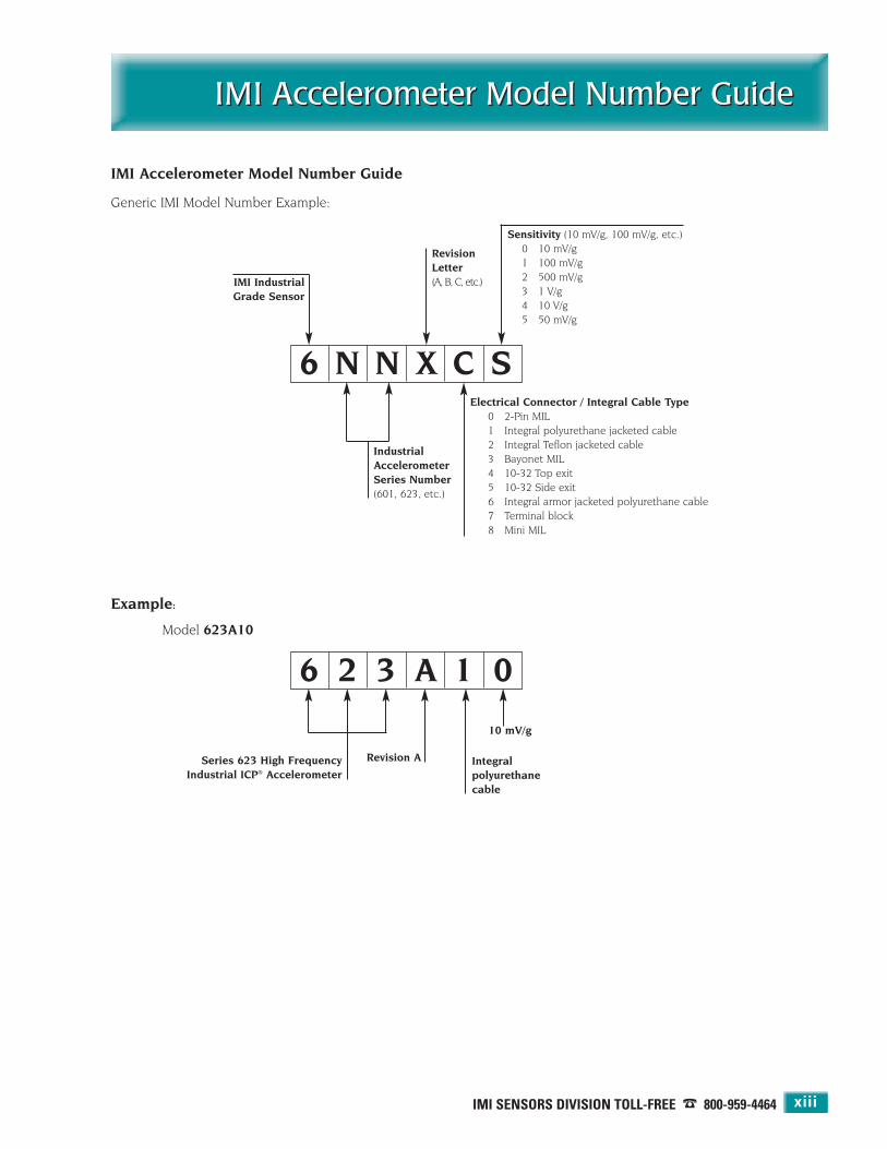
IMI Accelerometer Model Number GuideIMI Accelerometer Model Number Guide
IMI Accelerometer Model Number Guide
Generic IMI Model Number Example:
6 N N X C S
IMI Industrial Grade Sensor
Industrial Accelerometer Series Number(601, 623, etc.)
Revision Letter(A, B, C, etc.)
Electrical Connector / Integral Cable Type0 2-Pin MIL1 Integral polyurethane jacketed cable2 Integral Teflon jacketed cable3 Bayonet MIL4 10-32 Top exit5 10-32 Side exit6 Integral armor jacketed polyurethane cable 7 Terminal block8 Mini MIL
Sensitivity (10 mV/g, 100 mV/g, etc.)0 10 mV/g1 100 mV/g2 500 mV/g3 1 V/g4 10 V/g5 50 mV/g
6 2 3 A 1 0
Series 623 High FrequencyIndustrial ICP® Accelerometer
Revision A Integralpolyurethanecable
10 mV/g
Example:
Model 623A10

24-HOUR SENSORLINESM 716-684-0003 • WEB SITE — www.imi-sensors.comxiv
Accelerometer Summary TablesAccelerometer Summary Tables
Low-Cost, Industrial ICP® Accelerometers For Permanent InstallationSeries Sensitivity Frequency Amplitude Broadband Settling Temperature Connector Weight Page
(Nominal) Range (± 3 dB) Range Resolution Time Range Position603CX1 100 mV/g 30 to 600k cpm ± 50 g 350 µg ≤ 2 sec -65 to +250 °F top 1.8 oz 2, 3Ceramic 10.2 mV/(m/s2) 0.5 to 10k Hz ± 490 m/s2 3434 µm/s2 -54 to +121 °C 51 gm607AX1 100 mV/g 30 to 600k cpm ± 50 g 350 µg ≤ 2 sec -65 to +250 °F side 0.78 oz 4, 5Swiveler® 10.2 mV/(m/s2) 0.5 to 10k Hz ± 490 m/s2 3434 µm/s2 -54 to +121 °C 22 gm608A11 100 mV/g 30 to 600k cpm ± 50 g 350 µg ≤ 2 sec -65 to +250 °F top 3.5 oz 6Lowest Cost 10.2 mV/(m/s2) 0.5 to 10k Hz ± 490 m/s2 3434 µm/s2 -54 to +121 °C cable only 99 gm606BX1 100 mV/g 30 to 600k cpm ± 50 g 350 µg ≤ 2 sec -65 to +250 °F side 4.4 oz 8, 9Ring Style 10.2 mV/(m/s2) 0.5 to 10k Hz ± 490 m/s2 3434 µm/s2 -54 to +121 °C 124 gm601AX1 100 mV/g 16 to 600k cpm ± 50 g 50 µg ≤ 4 sec -65 to +250 °F top 2.8 oz 10Low Noise 10.2 mV/(m/s2) 0.27 to 10k Hz ± 490 m/s2 491 µm/s2 -54 to +121 °C 80 gm602CX1 100 mV/g 30 to 480k cpm ± 50 g 350 µg ≤ 2 sec -65 to +250 °F side 2.75 oz 10Through-hole 10.2 mV/(m/s2) 0.5 to 8k Hz ± 490 m/s2 3434 µm/s2 -54 to +121 °C 78 gm627AX1 100 mV/g 20 to 600k cpm ± 50 g 1000 µg ≤ 10 sec -65 to +250 °F top 3.3 oz 10Quartz 10.2 mV/(m/s2) 0.33 to 10k Hz ± 490 m/s2 9800 µm/s2 -54 to +121 °C 94 gm
Precision Industrial ICP® Accelerometers For Route-Based MeasurementsSeries Sensitivity Frequency Frequency Amplitude Broadband Settling Temperature Connector Weight Page
Range (± 10 %) Range (± 3 dB) Range Resolution Time Range Position622AX1 100 mV/g 25 to 300k cpm 12 to 600k cpm ± 50 g 50 µg ≤ 5 sec -65 to +250 °F top 3.3 oz 12, 13Ceramic 10.2 mV/(m/s2) 0.42 to 5000 Hz 0.2 to 10k Hz ± 490 m/s2 491 µm/s2 -54 to +121 °C 94 gm625BX1 100 mV/g 22 to 450k cpm 12 to 630k cpm ± 50 g 50 µg ≤ 8 sec -65 to +250 °F side 5.1 oz 14, 15Ceramic Ring 10.2 mV/(m/s2) 0.37 to 7500 Hz 0.2 to 10.5k Hz ± 490 m/s2 491 µm/s2 -54 to +121 °C 145 gm625BX0 10 mV/g 22 to 450k cpm 12 to 630k cpm ± 500 g 350 µg ≤ 8 sec -65 to +250 °F side 5.1 oz 16, 18High Range 1.02 mV/(m/s2) 0.37 to 7500 Hz 0.2 to 10.5k Hz ± 4900 m/s2 3434 µm/s2 -54 to +121 °C 145 gm628FX1 100 mV/g 40 to 390k cpm 20 to 720k cpm ± 50 g 1000 µg ≤ 10 sec -65 to +250 °F top 3.2 oz 16, 18Quartz 10.2 mV/(m/s2) 0.67 to 6500 Hz 0.33 to 12k Hz ± 490 m/s2 9800 µm/s2 -54 to +121 °C 91 gm624AX1 100 mV/g 102 to 420k cpm 48 to 600k cpm ± 50 g 1000 µg ≤ 10 sec -65 to +250 °F side 5.1 oz 16, 18Quartz Ring 10.2 mV/(m/s2) 1.7 to 7000 Hz 0.8 to 10k Hz ± 490 m/s2 9800 µm/s2 -54 to +121 °C 145 gmVO622AX1 100 mV/in/sec 240 to 270k cpm 180 to 540k cpm ± 50 in/s 450 µin/s ≤ 30 sec -65 to +250 °F top 3.3 oz 17, 18Velocity 3937 mV/m/s 4 to 4500 Hz 3 to 9000 Hz ± 1.27 m/s 11.4 µm/s -54 to +121 °C 93 gmVO625AX1 100 mV/in/sec 120 to 150k cpm 90 to 360k cpm ± 50 in/s 400 µin/s ≤ 30 sec -65 to +250 °F side 7.6 oz 17, 18Velocity 3937 mV/m/s 2 to 2500 Hz 1.5 to 6000 Hz ± 1.27 m/s 10.6 µm/s -54 to +121 °C 215 gmVO626AX1 100 mV/in/sec 120 to 150k cpm 90 to 360k cpm ± 50 in/s 300 µin/s ≤ 30 sec -65 to +250 °F top 7.8 oz 17, 18Velocity 3937 mV/m/s 2 to 2500 Hz 1.5 to 6000 Hz ± 1.27 m/s 7.62 µm/s -54 to +121 °C 221 gm

IMI SENSORS DIVISION TOLL-FREE � 800-959-4464 xv
Accelerometer Summary TablesAccelerometer Summary Tables
High Frequency Industrial ICP® AccelerometersSeries Sensitivity Frequency Frequency Amplitude Broadband Settling Temperature Connector Weight Page
Range (± 10 %) Range (± 3 dB) Range Resolution Time Range Position623CX0 10 mV/g 102 to 600k cpm 48 to 900k cpm ± 500 g 300 µg ≤ 3 sec -65 to +250 °F top 1.8 oz 20, 21Rugged 1.02 mV/(m/s2) 1.7 to 10k Hz 0.8 to 15k Hz ± 4900 m/s2 2943 µm/s2 -54 to +121 °C 51 gm623CX1 100 mV/g 102 to 600k cpm 48 to 900k cpm ± 50 g 100 µg ≤ 2 sec -65 to +250 °F top 1.8 oz 22, 23Rugged 10.2 mV/(m/s2) 1.7 to 10k Hz 0.8 to 15k Hz ± 490 m/s2 981 µm/s2 -54 to +121 °C 51 gm621B40 10 mV/g 204 to 1080k cpm 96 to 1800k cpm ± 500 g 1200 µg ≤ 3 sec -65 to +250 °F top 0.1 oz 24Miniature 1.02 mV/(m/s2) 3.4 to 18k Hz 1.6 to 30k Hz ± 4900 m/s2 1176 µm/s2 -54 to +121 °C 2.8 gm621B41 100 mV/g 102 to 900k cpm 48 to 1200k cpm ± 50 g 100 µg ≤ 5 sec -65 to +250 °F top 1.06 oz 25Lightweight 10.2 mV/(m/s2) 1.7 to 15k Hz 0.8 to 20k Hz ± 490 m/s2 981 µm/s2 -54 to +121 °C 30 gm621B51 100 mV/g 102 to 900k cpm 48 to 1200k cpm ± 50 g 100 µg ≤ 5 sec -65 to +250 °F side 1.06 oz 26Lightweight 10.2 mV/(m/s2) 1.7 to 15k Hz 0.8 to 20k Hz ± 490 m/s2 981 µm/s2 -54 to +121 °C 30 gm631A80 10 mV/g 68 to 840k cpm 32 to 960k cpm ± 500 g 450 µg ≤ 3 sec -65 to +250 °F side 2.12 oz 27Ring 1.02 mV/(m/s2) 1.1 to 14k Hz 0.53 to 16k Hz ± 4900 m/s2 4415 µm/s2 -54 to +121 °C 60 gm635A01 100 mV/g 68 to 720k cpm 32 to 900k cpm ± 50 g 240 µg ≤ 2 sec -65 to +250 °F side 3.0 oz 28Ring 10.2 mV/(m/s2) 1.1 to 12k Hz 0.53 to 15k Hz ± 490 m/s2 2354 µm/s2 -54 to +121 °C 86 gm
Low Frequency Industrial ICP® AccelerometersSeries Sensitivity Frequency Frequency Amplitude Broadband Settling Temperature Connector Weight Page
Range (± 10 %) Range (± 3 dB) Range Resolution Time Range Position625BX2 500 mV/g 22 to 240k cpm 12 to 360k cpm ± 10 g 15 µg ≤ 4.5 sec -65 to +250 °F side 6.1 oz 30, 31
51 mV/(m/s2) 0.37 to 4000 Hz 0.2 to 6000 Hz ± 98 m/s2 147 µm/s2 -54 to +121 °C 173 gm626AX1 100 mV/g 18 to 420k cpm 12 to 600k cpm ± 50 g 100 µg ≤ 5 sec -65 to +250 °F top 5.3 oz 32, 33
10.2 mV/(m/s2) 0.3 to 7000 Hz 0.2 to 10k Hz ± 490 m/s2 981 µm/s2 -54 to +121 °C 150 gm626AX4 10 V/g 4 to 18k cpm 2 to 30k cpm ± 0.5 g 0.5 µg ≤ 5 min 0 to +1 50 °F top 22 oz 34, 35
1.02 V/(m/s2) 0.07 to 300 Hz 0.03 to 500 Hz ± 4.9 m/s2 5 µm/s2 -18 to +65 °C 624 gm626AX2 500 mV/g 18 to 240k cpm 12 to 360k cpm ± 10 g 15 µg ≤ 5 sec -65 to +250 °F top 7.4 oz 36
51 mV/(m/s2) 0.3 to 4000 Hz 0.2 to 6000 Hz ± 98 m/s2 147 µm/s2 -54 to +121 °C 210 gm626AX3 1000 mV/g 18 to 240k cpm 12 to 360k cpm ± 5 g 10 µg ≤ 10 sec -65 to +250 °F top 7.4 oz 36
102 mV/(m/s2) 0.3 to 4000 Hz 0.2 to 6000 Hz ± 49 m/s2 98 µm/s2 -54 to +121 °C 210 gm
Multi-Axis Industrial ICP® AccelerometersSeries Sensitivity Frequency Frequency Amplitude Broadband Settling Temperature Connector Weight Page
Range (± 10 %) Range (± 3 dB) Range Resolution Time Range Position604BX1 100 mV/g 30 to 300k cpm ± 50 g 350 µg ≤ 2 sec -65 to +250 °F side 4.4 oz 38, 39Triaxial 10.2 mV/(m/s2) N/A 0.5 to 5000 Hz ± 490 m/s2 3434 µm/s2 -54 to +121 °C 124 gm605BX1 100 mV/g 30 to 300k cpm ± 50 g 350 µg ≤ 2 sec -65 to +250 °F side 4.4 oz 40, 41 Biaxial 10.2 mV/(m/s2) N/A 0.5 to 5000 Hz ± 490 m/s2 3434 µm/s2 -54 to +121 °C 124 gm629AX1 100 mV/g 102 to 300k cpm 48 to 480k cpm ± 50 g 100 µg ≤ 3 sec -65 to +250 °F side 4.9 oz 42, 43Triaxial 10.2 mV/(m/s2) 1.7 to 5000 Hz 0.8 to 8000 Hz ± 490 m/s2 981 µm/s2 -54 to +121 °C 139 gm629AX2 500 mV/g 102 to 300k cpm 48 to 480k cpm ± 10 g 120 µg ≤ 2 sec -65 to +200 °F side 4.9 oz 44, 45Triaxial 51 mV/(m/s2) 1.7 to 5000 Hz 0.8 to 8000 Hz ± 98 m/s2 1177 µm/s2 -54 to +94 °C 139 gm629M05 100 mV/g 120 to 420k cpm ± 50 g 560 µg ≤ 3.0 sec -65 to +250 °F top 4.3 oz 46Triaxial 10.2 mV/g N/A 2 to 7000 Hz ± 490 m/s2 5494 µm/s2 -54 to +121 °C cable 135 gm629M06 100 mV/g 90 to 360k cpm 48 to 720k cpm ± 50 g 560 µg ≤ 3.5 sec -65 to +250 °F side 5.7 oz 46Triaxial 10.2 mV/(m/s2) 1.5 to 6000 Hz 0.8 to 12k Hz ± 490 m/s2 5494 µm/s2 -54 to +121 °C 163 gm

24-HOUR SENSORLINESM 716-684-0003 • WEB SITE — www.imi-sensors.com
Accelerometer Summary TablesAccelerometer Summary Tables
xvi
High Temperature Industrial ICP® AccelerometersModel Sensitivity Frequency Frequency Amplitude Broadband Settling Temperature Connector Weight Page
Range (± 10 %) Range (± 3 dB) Range Resolution Time Range PositionHT622A01 100 mV/g 25 to 300k cpm 12 to 480k cpm ± 50 g 150 µg ≤ 5 sec -65 to +325 °F top 3.3 oz 48Ceramic 10.2 mV/(m/s2) 0.42 to 5000 Hz 0.2 to 8000 Hz ± 490 m/s2 -54 to +163 °C 93 gmHT623C01 100 mV/g 102 to 540k cpm 48 to 900k cpm ± 50 g 300 µg ≤ 1 sec -65 to +325 °F top 1.8 oz 48High Freq. 10.2 mV/(m/s2) 1.7 to 9000 Hz 0.8 to 15k Hz ± 490 m/s2 -54 to +163 °C 51 gmHT625B01 100 mV/g 22 to 360k cpm 12 to 600k cpm ± 50 g 200 µg ≤ 8 sec -65 to +325 °F side 5.1 oz 48Low Freq. 10.2 mV/(m/s2) 0.37 to 6000 Hz 0.2 to 10k Hz ± 490 m/s2 -54 to +163 °C 145 gmHT628F01 100 mV/g 102 to 300k cpm 48 to 480k cpm ± 50 g 1000 µg ≤ 3 sec -65 to +325 °F top 3.2 oz 49 Quartz 10.2 mV/(m/s2) 1.7 to 5000 Hz 0.8 to 8000 Hz ± 490 m/s2 -54 to +163 °C 91 gmHT624A01 100 mV/g 102 to 180k cpm 48 to 300k cpm ± 50 g 1000 µg ≤ 3 sec -65 to +325 °F side 5.1 oz 49Quartz Ring 10.2 mV/(m/s2) 1.7 to 3000 Hz 0.8 to 5000 Hz ± 490 m/s2 -54 to +163 °C 145 gm
High Temperature, Charge-Mode, Industrial Accelerometer KitsMODEL Sensitivity Frequency Frequency Amplitude Broadband Settling Temperature Connector Weight Page
Range (± 10 %) Range (± 3 dB) Range Resolution Time Range (Sensor) Position (Sensor)600A06 10 mV/g 100 to 180k cpm 60 to 600k cpm ± 250 g 410 µg ≤ 15 sec -65 to +500 °F top 2.95 oz 51
1.02 mV/(m/s2) 1.67 to 3000 Hz 1 to 10k Hz ± 2452 m/s2 -54 to +260 °C 84 gm600A08 10 mV/g 100 to 180k cpm 60 to 600k cpm ± 250 g 410 µg ≤ 15 sec -65 to +500 °F top 2.95 oz 51
1.02 mV/(m/s2) 1.67 to 3000 Hz 1 to 10k Hz ± 2452 m/s2 -54 to +260 °C 84 gm600A02 100 mV/g 100 to 180k cpm 60 to 600k cpm ± 25 g 120 µg ≤ 15 sec -65 to +500 °F top 2.95 oz 51
10.2 mV/(m/s2) 1.67 to 3000 Hz 1 to 10k Hz ± 245 m/s2 -54 to +260 °C 84 gm600A03 100 mV/g 100 to 180k cpm 60 to 600k cpm ± 25 g 120 µg ≤ 15 sec -65 to +500 °F top 2.95 oz 51
10.2 mV/(m/s2) 1.67 to 3000 Hz 1 to 10k Hz ± 245 m/s2 -54 to +260 °C 84 gm600A07 1000 mV/g 100 to 180k cpm 60 to 600k cpm ± 2.5 g 120 µg ≤ 15 sec -65 to +500 °F top 2.95 oz 51
102 mV/(m/s2) 1.67 to 3000 Hz 1 to 10k Hz ± 24.5 m/s2 -54 to +260 °C 84 gm600A09 1000 mV/g 100 to 180k cpm 60 to 600k cpm ± 2.5 g 120 µg ≤ 15 sec -65 to +500 °F top 2.95 oz 51
102 mV/(m/s2) 1.67 to 3000 Hz 1 to 10k Hz ± 24.5 m/s2 -54 to +260 °C 84 gm
High Temperature, Charge-Mode, Industrial AccelerometerModel Sensitivity Frequency Frequency Shock Temperature Connector Weight Page
Range (± 5 %) Range (± 3 dB) Limit Range (Sensor) Position (Sensor)612A01 26 pC/g 300k cpm 600k cpm 5000 g pk -65 to +500 °F top 2.95 oz 50, 52
2.6 pC/m/s2 5000 Hz 10k Hz 49k m/s2 pk -54 to +260 °C 84 gm

IMI SENSORS DIVISION TOLL-FREE � 800-959-4464
Accelerometer Summary TablesAccelerometer Summary Tables
xvii
4-20 mA Vibration Sensing TransmittersModel Current Measured Frequency Amplitude Broadband Settling Temperature Connector Weight Page
Output Parameter Range (± 10 %) Range Resolution Time Range Position640AX0 4 to 20 mA Peak Velocity 180 to 60k cpm 0 to 0.5 in/s pk 0.005 in/s pk ≤ 60 sec -40 to +185 °F top 3.17 oz 54
3 to 1000 Hz 0 to 12.7 mm/s pk 0.13 mm/s pk -40 to +85 °C 90 gm640AX1 4 to 20 mA Peak Velocity 180 to 60k cpm 0 to 1.0 in/s pk 0.005 in/s pk ≤ 60 sec -40 to +185 °F top 3.17 oz 54
3 to 1000 Hz 0 to 25.4 mm/s pk 0.13 mm/s pk -40 to +85 °C 90 gm640AX2 4 to 20 mA Peak Velocity 180 to 60k cpm 0 to 2.0 in/s pk 0.01 in/s pk ≤ 60 sec -40 to +185 °F top 3.17 oz 54
3 to 1000 Hz 0 to 50.8 mm/s pk 0.26 mm/s pk -40 to +85 °C 90 gm641AX0 4 to 20 mA RMS Velocity 600 to 60k cpm 0 to 0.5 in/s rms 0.005 in/s rms ≤ 60 sec -40 to +185 °F top 3.17 oz 55
10 to 1000 Hz 0 to 12.7 mm/s rms 0.13 mm/s rms -40 to +85 °C 90 gm641AX1 4 to 20 mA RMS Velocity 600 to 60k cpm 0 to 1.0 in/s rms 0.005 in/s rms ≤ 60 sec -40 to +185 °F top 3.17 oz 55
10 to 1000 Hz 0 to 25.4 mm/s rms 0.13 mm/s rms -40 to +85 °C 90 gm641AX2 4 to 20 mA RMS Velocity 600 to 60k cpm 0 to 2.0 in/s rms 0.01 in/s rms ≤ 60 sec -40 to +185 °F top 3.17 oz 55
10 to 1000 Hz 0 to 50.8 mm/s rms 0.26 mm/s rms -40 to +85 °C 90 gm645AX0 4 to 20 mA RMS Acceleration 180 to 60k cpm 0 to 5 g rms 0.025 g rms ≤ 30 sec -40 to +185 °F top 3.17 oz 56
3 to 1000 Hz 0 to 49 m/s2 rms 0.24 m/s2 rms -40 to +85 °C 90 gm645AX1 4 to 20 mA RMS Acceleration 180 to 300k cpm 0 to 5 g rms 0.025 g rms ≤ 30 sec -40 to +185 °F top 3.17 oz 56
3 to 5000 Hz 0 to 49 m/s2 rms 0.24 m/s2 rms -40 to +85 °C 90 gm645AX2 4 to 20 mA RMS Acceleration 180 to 600k cpm 0 to 5 g rms 0.025 g rms ≤ 30 sec -40 to +185 °F top 3.17 oz 56
3 to 10k Hz 0 to 49 m/s2 rms 0.24 m/s2 rms -40 to +85 °C 90 gm646AX0 4 to 20 mA RMS Acceleration 180 to 60k cpm 0 to 10 g rms 0.05 g rms ≤ 30 sec -40 to +185 °F top 3.17 oz 57
3 to 1000 Hz 0 to 98.1 m/s2 rms 0.5 m/s2 rms -40 to +85 °C 90 gm646AX1 4 to 20 mA RMS Acceleration 180 to 300k cpm 0 to 10 g rms 0.05 g rms ≤ 30 sec -40 to +185 °F top 3.17 oz 57
3 to 5k Hz 0 to 98.1 m/s2 rms 0.5 m/s2 rms -40 to +85 °C 90 gm646AX2 4 to 20 mA RMS Acceleration 180 to 600k cpm 0 to 10 g rms 0.05 g rms ≤ 30 sec -40 to +185 °F top 3.17 oz 57
3 to 10k Hz 0 to 98.1 m/s2 rms 0.5 m/s2 rms -40 to +85 °C 90 gm
DC Response, Industrial Capacitive AccelerometersSeries Sensitivity Frequency Frequency Amplitude Broadband Temperature Connector Weight Page
Range (± 5 %) Range (± 10 %) Range Resolution Range Position650AX0 10 mV/g 0 to 48k cpm 0 to 60k cpm ± 200 g pk 450 µg rms -40 to +185 °F top 2.7 oz 60
1.02 mV/(m/s2) 0 to 800 Hz 0 to 1000 Hz ± 1960 m/s2 pk 4410 µm/s2 rms -40 to +85 °C 77 gm650AX5 50 mV/g 0 to 27k cpm 0 to 36k cpm ± 50 g pk 120 µg rms -40 to +185 °F top 2.7 oz 60
5.1 mV/(m/s2) 0 to 450 Hz 0 to 600 Hz ± 490 m/s2 pk 1180 µm/s2 rms -40 to +85 °C 77 gm650AX1 100 mV/g 0 to 18k cpm 0 to 30k cpm ± 20 g pk 80 µg rms -40 to +185 °F top 2.7 oz 61
10.2 mV/(m/s2) 0 to 300 Hz 0 to 500 Hz ± 196 m/s2 pk 800 µm/s2 rms -40 to +85 °C 77 gm650AX4 1000 mV/g 0 to 6000 cpm 0 to 9000 cpm ± 3 g pk 30 µg rms -40 to +185 °F top 2.7 oz 61
102 mV/(m/s2) 0 to 100 Hz 0 to 150 Hz ± 29 m/s2 pk 295 µm/s2 rms -40 to +85 °C 77 gm

24-HOUR SENSORLINESM 716-684-0003 • WEB SITE — www.imi-sensors.com
Accelerometer Summary TablesAccelerometer Summary Tables
xviii
Intrinsically Safe Industrial ICP® Accelerometers (See Pages 83-86 for I.S. Barriers)Series Sensitivity Frequency Frequency Amplitude Broadband Settling Temperature Connector Weight Page
Range (± 10 %) Range (± 3 dB) Range Resolution Time Range Position622AX1* 100 mV/g 25 to 300k cpm 12 to 600k cpm ± 50 g 50 µg ≤ 5 sec -65 to +250 °F top 3.3 oz 12, 13Ceramic 10.2 mV/(m/s2) 0.42 to 5000 Hz 0.2 to 10k Hz ± 490 m/s2 491 µm/s2 -54 to +121 °C 94 gm625BX1** 100 mV/g 22 to 450k cpm 12 to 630k cpm ± 50 g 50 µg ≤ 8 sec -65 to +250 °F side 5.1 oz 14, 15Ceramic Ring 10.2 mV/(m/s2) 0.37 to 7500 Hz 0.2 to 10.5k Hz ± 490 m/s2 491 µm/s2 -54 to +121 °C 145 gm628FX1† 100 mV/g 40 to 390k cpm 20 to 720k cpm ± 50 g 1000 µg ≤ 10 sec -65 to +250 °F top 3.2 oz 16Quartz 10.2 mV/(m/s2) 0.67 to 6500 Hz 0.33 to 12k Hz ± 490 m/s2 9800 µm/s2 -54 to +121 °C 91 gmVO622AX1§ 100 mV/in/sec 240 to 270k cpm 180 to 540k cpm ± 50 in/s 450 µin/s ≤ 30 sec -65 to +250 °F top 3.3 oz 17Velocity 3937 mV/m/s 4 to 4500 Hz 3 to 9000 Hz ± 1.27 m/s 11.4 µm/s -54 to +121 °C 93 gm623CX0† 10 mV/g 102 to 600k cpm 48 to 900k cpm ± 500 g 300 µg ≤ 3 sec -65 to +250 °F top 1.8 oz 20, 21High Freq. 1.02 mV/(m/s2) 1.7 to 10k Hz 0.8 to 15k Hz ± 4900 m/s2 2943 µm/s2 -54 to +121 °C 51 gm623CX1† 100 mV/g 102 to 600k cpm 48 to 900k cpm ± 50 g 100 µg ≤ 2 sec -65 to +250 °F top 1.8 oz 22, 23High Freq. 10.2 mV/(m/s2) 1.7 to 10k Hz 0.8 to 15k Hz ± 490 m/s2 981 µm/s2 -54 to +121 °C 51 gm
NOTES: * Available approvals are: CS-Canadian Standards Association, EX-CENELEC, FM-Factory Mutual, MS-Mine Safety and Health Administration,and MX-CENELEC for mining
** Available approvals are: CS-Canadian Standards Association and FM-Factory Mutual† Available approvals are: CS-Canadian Standards Association, EX-CENELEC, and FM-Factory Mutual§ Available approvals are: CS-Canadian Standards Association, EX-CENELEC, FM-Factory Mutual, and MX-CENELEC for mining
In addition, all 4-20 mA vibration sensing transmitters (Series 640) offer CS-Canadian Standards Association, EX-CENELEC, and FM-Factory Mutual approvals. See pages 53 to 58.
Velocity Output Industrial ICP® SensorsSeries Sensitivity Frequency Frequency Amplitude Broadband Settling Temperature Connector Weight Page
Range (± 10 %) Range (± 3 dB) Range Resolution Time Range PositionVO622AX1 100 mV/in/sec 240 to 270k cpm 180 to 540k cpm ± 50 in/s 450 µin/s ≤ 30 sec -65 to +250 °F top 3.3 oz 17, 18High Freq. 3937 mV/m/s 4 to 4500 Hz 3 to 9000 Hz ± 1.27 m/s 11.4 µm/s -54 to +121 °C 93 gmVO625AX1 100 mV/in/sec 120 to 150k cpm 90 to 360k cpm ± 50 in/s 400 µin/s ≤ 30 sec -65 to +250 °F side 7.6 oz 17, 18Ring 3937 mV/m/s 2 to 2500 Hz 1.5 to 6000 Hz ± 1.27 m/s 10.6 µm/s -54 to +121 °C 215 gmVO626AX1 100 mV/in/sec 120 to 150k cpm 90 to 360k cpm ± 50 in/s 300 µin/s ≤ 30 sec -65 to +250 °F top 7.8 oz 17, 18Low Freq. 3937 mV/m/s 2 to 2500 Hz 1.5 to 6000 Hz ± 1.27 m/s 7.62 µm/s -54 to +121 °C 221 gm

IMI SENSORS DIVISION TOLL-FREE � 800-959-4464
Options for Industrial Vibration SensorsOptions for Industrial Vibration Sensors
xix
It is often desirable to incorporate various options in anaccelerometer to enhance or improve its performance for agiven application. To designate an option for a specificmodel, first check to ensure that it is available by findingthe option prefix letter in the model’s specification chart.The prefix letter is then inserted in front of the model number to designate the option (e.g.,TO622A01).
Note: More than one option may be designated (e.g.,FMVO622A01). The following descriptions address theimpact any option may have on specifications and performance. If in doubt about the compatibility of anyoption for the accelerometer model of interest, or theeffects any option may introduce for your application, calla factory application engineer for assistance.
How to Specify an Option
The tables on the following pages (xx-xxii) describe each of the options listed below in greater detail.
CS — Canadian Standards Association Approved Intrinsically Safe
EP — Explosion Proof Condulet Enclosure
EX — CENELEC Approved Intrinsically Safe
F* — Operation from 220 VAC Power
FM — Factory Mutual Approved Intrinsically Safe
HT — High Temperature Operation
LB — Low Bias Operation
M — Metric Installation
MO* — Multiple Output
MS — Mine Safety Administration Approved Intrinsically Safe
MX — CENELEC Approved Intrinsically Safe for Mining per I M2 EEx ia I
PS* — Painted Steel Enclosure
RV — Raw Vibration (Analog Acceleration) Output Signal
R* — Rechargeable (includes AC powered recharger and rechargeable batteries)
SS* — Stainless Steel Enclosure
TO — Temperature Output Signal
VO — Velocity Output Signal
XSS* — 316L Stainless Steel Enclosure
* Designates an option available for electronic products for which detailed descriptions appear in the product section.
Brief Description of Option Letters
24-HOUR SENSORLINESM 716-684-0003 • WEB SITE — www.imi-sensors.com
Options for Industrial Vibration SensorsOptions for Industrial Vibration Sensors
xx
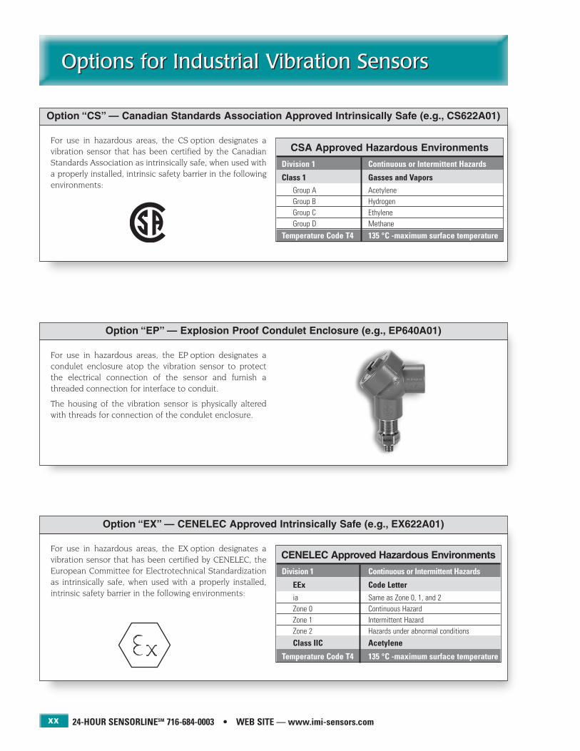
For use in hazardous areas, the EX option designates avibration sensor that has been certified by CENELEC, theEuropean Committee for Electrotechnical Standardizationas intrinsically safe, when used with a properly installed,intrinsic safety barrier in the following environments:
Option “EX” — CENELEC Approved Intrinsically Safe (e.g., EX622A01)
CENELEC Approved Hazardous Environments
Division 1 Continuous or Intermittent Hazards
EEx Code Letteria Same as Zone 0, 1, and 2Zone 0 Continuous HazardZone 1 Intermittent HazardZone 2 Hazards under abnormal conditions
Class IIC Acetylene
Temperature Code T4 135 °C -maximum surface temperature
For use in hazardous areas, the CS option designates a vibration sensor that has been certified by the CanadianStandards Association as intrinsically safe, when used witha properly installed, intrinsic safety barrier in the followingenvironments:
Option “CS” — Canadian Standards Association Approved Intrinsically Safe (e.g., CS622A01)
For use in hazardous areas, the EP option designates a condulet enclosure atop the vibration sensor to protectthe electrical connection of the sensor and furnish athreaded connection for interface to conduit.
The housing of the vibration sensor is physically alteredwith threads for connection of the condulet enclosure.
Option “EP” — Explosion Proof Condulet Enclosure (e.g., EP640A01)
CSA Approved Hazardous Environments
Division 1 Continuous or Intermittent Hazards
Class 1 Gasses and VaporsGroup A AcetyleneGroup B HydrogenGroup C EthyleneGroup D Methane
Temperature Code T4 135 °C -maximum surface temperature

IMI SENSORS DIVISION TOLL-FREE � 800-959-4464
Options for Industrial Vibration SensorsOptions for Industrial Vibration Sensors
xxi
This option permits installation of the vibration sensor intoa tapped hole having a metric thread. It simply designatesa change in the supplied mounting stud, screw, or bolt.Metric mounting studs are adaptor studs that have an
english thread on the end that screws into the sensor base,and a metric thread on the other end that screws into the test specimen. Metric screws or bolts are used forthrough-hole mounted sensors.
Option “M” — Metric Installation (e.g., M603C01)
An adjustment to the built-in microelectronic circuitryreduces the output bias voltage to approximately 4.5 to 6.5VDC. This permits the sensor to operate from a reduced,minimum, excitation voltage of 9 VDC. This may be desirablewhen incorporating an accelerometer into an OEM systemand the voltage available for excitation is limited. Also,some vibration data collectors, readout devices, or analyzers,
that incorporate excitation power, may provide only alower voltage than the 18 VDC that is normally recommended for standard sensors. The low bias optionlimits the amplitude range of the sensor to ± 3 volts output. For example, a 100 mV/g accelerometer, with lowbias operation, becomes limited to a ± 30 g range.
Option “LB” — Low Bias Operation (e.g., LB622A01)
For use in hazardous areas, the FM option designates avibration sensor that has been certified by Factory Mutualas intrinsically safe, when used with a properly installed,intrinsic safety barrier in the following environments:
Option “FM” — Factory Mutual Approved Intrinsically Safe (e.g., FM622A01)
An adjustment to the built-in microelectronic circuitry permits sensor operation to temperatures that exceed thenormal operating temperature range. Typically, the frequency range of the sensor is somewhat compromised
and the output impedance is raised to <500 ohm. Checkwith the factory to determine the allowable high temperaturecapability for a specific model and the impact this optionwill have on frequency range.
Option “HT” — High Temperature Operation (e.g., HT622A01)
FM Approved Hazardous Environments
Division 1 Continuous or Intermittent Hazards
Class 1 Gasses and VaporsGroup A AcetyleneGroup B HydrogenGroup C EthyleneGroup D Methane
Class 2 DustsGroup E Metal DustGroup F Coal DustGroup G Grain Dust
Class 3 Fibers (no sub groups)
Temperature Code T4 135 °C -maximum surface temperature

For hazardous area use, the MX option designates a vibrationsensor that has been certified by CENELEC as intrinsicallysafe, when used with a properly installed, intrinsic safetybarrier in the following environments:
Option “MX” — CENELEC Approved Intrinsically Safe for Mining per I M2 EEx ia I (e.g., MX622A01)
24-HOUR SENSORLINESM 716-684-0003 • WEB SITE — www.imi-sensors.com
Options for Industrial Vibration SensorsOptions for Industrial Vibration Sensors
xxii
This option adds a built-in signal integrator for convertingthe analog acceleration signal into an analog velocity signal.Often, velocity is the vibration measurement parameter of
choice for machinery vibration monitoring applications.
Option “VO” — Velocity Output Signal (e.g., VO622A01)
For 4-20 mA vibration sensing transmitters, the RV optionprovides a third connector pin, or integral cable lead, uponwhich the analog acceleration signal is present and availablefor readout, recording, frequency analysis, and diagnosticpurposes.
Option “RV” — Raw Vibration (Analog Acceleration) Output Signal (e.g., RV640A01)
This option adds a built-in temperature sensor and thirdconnector pin, or integral cable lead, upon which a 10mV/°C temperature output signal is present.
Option “TO” — Temperature Output Signal (e.g., TO622AX1)
Pin A: Signal/PowerPin B: CommonPin C: Temperature Output
For use in hazardous areas, the MS option designates a vibration sensor that has been certified by the UnitedStates Department of Labor, Mine Safety and HealthAdministration as intrinsically safe, when used with a properly installed, intrinsic safety barrier in the followingenvironments:
Option “MS” — Mine Safety Administration Approved Intrinsically Safe (e.g., MS622A01)
MSHA Approved Hazardous Environments
Division 1 Continuous or Intermittent Hazards
Class 1 Gasses and VaporsGroup D Methane
Class 2 DustsGroup F Coal Dust
Pin A: +4-20 mAPin B: -4-20 mAPin C: Analog Acceleration
For 4-20 mA vibration sensing transmitters, the RV optionprovides a third connector pin, or integral cable lead, uponwhich the analog acceleration signal is present and availablefor readout, recording, frequency analysis, and diagnosticpurposes.
Option “RV” — Raw Vibration (Analog Acceleration) Output Signal (e.g., RV640A01)
Pin A: +4-20 mAPin B: -4-20 mAPin C: Analog Acceleration
(Sensor connector shown)
(Sensor connector shown)
CENELEC For Mining Approved Hazardous Environments
Division 1 Continuous or Intermittent Hazards
EEx Code Letteria Same as Zone 0, 1, and 2Zone 0 Continuous HazardZone 1 Intermittent HazardZone 2 Hazards under abnormal conditions
Group I MethaneEquipment Group I Category M-2
Temperature Code T4 135 °C -maximum surface temperature

IMI SENSORS DIVISION TOLL-FREE � 800-959-4464
Typical Industrial VibrationMeasurement Systems
Typical Industrial VibrationMeasurement Systems
xxiii
Typical Diagnostic or Analysis System
Industrial vibration sensors are implemented into measurementsystems in a number of different ways. The installationtechnique typically falls into one of two categories, eitherpermanently mounted, or carried from point to point in aroute based measurement or analysis scheme. The entiremeasurement system, however, can take on a variety of
forms, depending on sensor type used and the goal of themonitoring program. This section highlights many of thepopular or recommended approaches, which comprisecomplete industrial vibration measurement and monitoringsystems.
Typical Point to Point, Route Based, Vibration Data Collection System
Typical Inaccessible Motor Monitoring System
Precision IndustrialAccelerometer
Precision IndustrialICP® Accelerometer
Magnetic Mounting Base Vibration Data Collector
Vibration DataCollector
FFT Analyzer, Recorder, orData Acquisition System
Sensor to DataCollector Cable
Sensor to DataCollector Cable
Sensor Cables
Sensor Cable Output Cable
ICP® Sensor SignalConditioner
Switch Box
Permanently Installed,Low-Cost
Accelerometers forAxial and Radial
Vibration Monitoring

24-HOUR SENSORLINESM 716-684-0003 • WEB SITE — www.imi-sensors.com
Typical Industrial VibrationMeasurement SystemsTypical Industrial VibrationMeasurement Systems
xxiv
Typical 4-20 mA, Continuous Vibration Level, Monitoring System with Diagnostic Capability
Typical Continuous Analog Signal Monitoring System
Typical 4-20 mA, Continuous Vibration Level, Monitoring System
Typical 4-20 mA Vibration Transmitter System
4-20 mA VibrationSensor
4-20 mA VibrationSensor with OptionalSimultaneous Analog
Output Signal(Option “RV”)
Sensor Cable
Analog Signal
4-20 mA Signal
PLC, DCS, Alarm, orSCADA System
PLC, DCS, Alarm, or SCADASystem for Continuous
Monitoring
Junction Boxwith Multiple
Output OptionMultiplexor
Monitoring System withSpectrum Enveloping
and Alarming
Multi-ChannelCable
Sensor Cables
Control andInterface Cables
Sensor Cable
4-20 mA SignalCable
Analog SignalCable
PLC, DCS, Alarm, orSCADA System
Permanently Installed,Low-Cost, ICP®
Accelerometer
Vibration Transmitter,Analog Signal Input,4-20 mA and Analog
Signal Outputs Vibration Data Collector or FFTAnalyzer for Signal Analysis
and Diagnostic Purposes
Vibration Data Collector or FFTAnalyzer for Signal Analysis
and Diagnostic Purposes
Permanently Installed,Low-Cost
Accelerometers forAxial and Radial MotorVibration Monitoring

IMI SENSORS DIVISION TOLL-FREE � 800-959-4464
Typical Industrial VibrationMeasurement Systems
Typical Industrial VibrationMeasurement Systems
xxv
Typical Intrinsically Safe Installation
Typical High Temperature, Charge-Mode, Sensor Kit Installation
Typical System for Vibration Sensor with Simultaneous Temperature Output Option
Typical Multi-Channel, Simultaneous Vibration and Temperature Monitoring System
Approved,Intrinsically SafeAccelerometer
Hazardous Area Safe Area
Low-Noise, HighTemperature Cable
Charge Converter
Output Cable
Vibration DataCollector or Analyzer
with ICP® Sensor Power
Vibration DataCollector or Analyzer
with ICP® Sensor Power
Two-ChannelVibration and Temperature
Data Collector
Two-ChannelVibration and Temperature
Data Collector
Sensor to DataCollector Cable
3 or 4-conductorSensor Cable
3 or 4-conductorSensor Cables
IndustrialAccelerometer with
SimultaneousTemperature Output
Option
Switch BoxPermanently Installed, Low-Cost Accelerometers, with
Temperature OutputOption, for Axial and RadialVibration Monitoring, and
Bearing TemperatureMonitoring
Sensor Cable
Intrinsic SafetyBarrier
Output Cable
High Temperature Zone
Charge ModeIndustrial
Accelerometer

24-HOUR SENSORLINESM 716-684-0003 • WEB SITE — www.imi-sensors.com
Industrial Accelerometer ApplicationsIndustrial Accelerometer Applications
xxvi
Monitoring vibration levels of critical pieces of machinery will lead to further productivity andreduced costs. Maintenance requirements can be pin-pointed, planned for, and scheduled during
routine shut downs rather than being faced with an unplanned outage or catastrophic system failure.
Technicians connect a vibration data collector to an IMI Junction Box to gathermeasurement data from industrial accelerometers located in inaccessible areas.

1
PCB 716-684-0001 IMI Sensors Division toll-free 800-959-4464 Fax 716-684-3823 E-mail [email protected] Web site www.imi-sensors.com
Low-Cost, Industrial ICP® Accelerometers
For Permanent Installation
Low-Cost, Industrial ICP® Accelerometers
For Permanent Installation
Low-cost, industrial ICP® accelerometers are recommendedfor permanent installation onto machinery to satisfy vibrationtrending requirements in Predictive Maintenance andCondition Monitoring applications. Lower cost is achieved byrelaxing the tolerance on sensitivity from unit to unit and by calibrating at only one reference frequency point, typically100 Hz. Measurement accuracy is compromised only if thesensor’s nominal sensitivity is used. If the provided single-point sensitivity is used, accuracy is very good.
Since low-cost sensors carry a wider sensitivity tolerance, theactual measurement obtained using the nominal sensitivityvalue may not be as quantitatively accurate as could beachieved if one uses the supplied reference sensitivity value.This disparity, however, may be irrelevant since when trending,the user is primarily interested in recognizing changes in theoverall measured vibration amplitude, or frequency signatureof the machinery. When comparing against previously acquireddata obtained with the same sensor in the same location, theexcellent repeatability of these piezoelectric vibration sensorsbecomes the vital attribute for successful trending requirements.
The user benefits by being able to employ a lower cost sensor, which in turn, makes monitoring additional
measurement points a more attractive undertaking.
Within this category, the Swiveler® series of accelerometers is offered. The unique mounting capabilityof these sensors permits the cable or connector to beoriented in any direction, which simplifies installationand reduces overall size. When small size is paramount,you will want to consider the Swiveler®.
The Spindler® accelerometer offers unique advantagesfor high-speed spindle vibration monitoring applica-
tions. Offering swivel mounting for ease of installation,the Spindler® also includes a sealed, armored, integral
cable which stands up against cutting fluids and flying metalchips. In addition, electronic filtering prevents saturationproblems while maintaining the ability to respond to high fre-quency vibrations.
Low profile designs
100 mV/g sensitivities
Top or side exit connector versions
Hermetically sealed construction
Long distance signal transmission
Swiveler®, Spindler®, ring, andthrough-hole styles for ease of connector orientation
Single frequency N.I.S.T. traceable calibration
Optional temperature output signal

24-HOUR SENSORLINESM 716-684-0003 • WEB SITE — www.imi-sensors.com
Low-Cost, Industrial ICP® AccelerometersFor Permanent InstallationLow-Cost, Industrial ICP® AccelerometersFor Permanent Installation
2
Series 603CX1
100 mV/g sensitivity
Small size
High frequency
Top exit connectors
Model 603C01with 2-pin, threaded military connector
Dimensions shown are in inches (millimeters).
Series 603CX1 Sensitivity Deviation vs. Temperature
Series 603CX1 Frequency Response
Actual Size
Model 603C01 Specifications
Dynamic Performance English SISensitivity (± 20%) 100 mV/g 10.2 mV/(m/s2)Measurement Range ± 50 g ± 490 m/s2
Broadband Resolution (1 to 10k Hz) 350 µg 3434 µm/s2
Frequency Range (± 3 dB) 30 to 600k cpm 0.5 to 10k HzMounted Resonant Frequency 1500k cpm 25k HzAmplitude Linearity ± 1% ± 1%Transverse Sensitivity ≤ 7% ≤ 7%
EnvironmentalShock Limit 5,000 g pk 49k m/s2 pkTemperature Range -65 to +250 °F -54 to +121 °C
ElectricalSettling Time ≤ 2.0 sec ≤ 2.0 secDischarge Time Constant ≥ 0.3 sec ≥ 0.3 secExcitation Voltage 18 to 28 VDC 18 to 28 VDCExcitation Constant Current 2 to 20 mA 2 to 20 mAOutput Impedance < 150 ohm < 150 ohmOutput Bias Voltage 8 to 12 VDC 8 to 12 VDCElectrical Case Isolation > 108 ohm > 108 ohm
MechanicalSize (hex × height) 11/16 × 1.65 in 11/16 in × 42 mmWeight 1.8 oz 51 gmMounting Thread 1/4-28 UNF-2B 1/4-28 UNF-2BMounting Torque 2 to 5 ft-lb 2.7 to 6.8 N-mSensing Element ceramic/shear ceramic/shearCase Material stainless steel stainless steelSealing (welded) hermetic IP68Electrical Connector, 2-pin (top) MIL-C-5015 MIL-C-5015
Supplied AccessoriesModel 081A40 Mounting Stud (1)Single Point Calibration at 100 Hz (NIST traceable)
Options (indicate using prefix letter shown)M — Metric installation via supplied M081A61 stud, 1/4-28 to M6 × 1.0
TO — Temperature Output available on alternate configurations: Models TO603A01, TO603A11, and TO603A61. Specifications may vary — consult factory

IMI SENSORS DIVISION TOLL-FREE � 800-959-4464
Low-Cost, Industrial ICP® AccelerometersFor Permanent Installation
Low-Cost, Industrial ICP® AccelerometersFor Permanent Installation
3
Series 603CX1 — additional base model configurations
Available models in this series Accelerometers Accelerometers with additional temperature output signal of 10 mV/ ºC
Two-pin, threaded military connector 603C01 TO603A01*†
Integral, 10 ft (3 m) polyurethane cable 603C11 TO603A11*
Integral, 10 ft (3 m) Teflon cable 603C21 —Three-pin, bayonet military connector 603C31 —Integral, 10 ft (3 m) steel-armored, polyurethane cable 603C61 TO603A61*
Options (indicate using prefix letter shown)M — Metric installation via supplied M081A61 stud, 1/4-28 to M6 × 1.0
NOTES: * Alternate configuration, specifications may vary — consult factory† Model TO603A01 has a 3-pin, threaded military connector to accommodate the additional temperature output signal.
Model 603C21 with integral, 10 ft (3 m) Teflon cable
Model 603C11 with integral, 10 ft (3 m) polyurethane cable
Model 603C61 with integral, 10 ft (3 m) steel-armored, polyurethane cable
Model 603C31 with 3-pin, bayonet military connector

24-HOUR SENSORLINESM 716-684-0003 • WEB SITE — www.imi-sensors.com
Low-Cost, Industrial ICP® AccelerometersFor Permanent InstallationLow-Cost, Industrial ICP® AccelerometersFor Permanent Installation
4
Series 607AX1
Swivel mount simplifies installation
Cable may be positioned in any direction
100 mV/g sensitivity
Small size
High frequency
Side exit connectors
The Swiveler®
Patent pending
Model 607A11 with integral, 10 ft (3 m) polyurethane cable
Dimensions shown are in inches (millimeters).
Actual Size
Model 607A11 Specifications
Dynamic Performance English SISensitivity (± 15%) 100 mV/g 10.2 mV/(m/s2)Measurement Range ± 50 g ± 490 m/s2
Broadband Resolution (1 to 10k Hz) 350 µg 3434 µm/s2
Frequency Range (± 3 dB) 30 to 600k cpm 0.5 to 10k HzMounted Resonant Frequency 1500k cpm 25k HzAmplitude Linearity ± 1% ± 1%Transverse Sensitivity ≤ 7% ≤ 7%
EnvironmentalShock Limit 5,000 g pk 49k m/s2 pkTemperature Range -65 to +250 °F -54 to +121 °C
ElectricalSettling Time ≤ 2 sec ≤ 2 secDischarge Time Constant ≥ 0.3 sec ≥ 0.3 secExcitation Voltage 18 to 28 VDC 18 to 28 VDCExcitation Constant Current 2 to 20 mA 2 to 20 mAOutput Impedance < 150 ohm < 150 ohmOutput Bias Voltage 8 to 12 VDC 8 to 12 VDCElectrical Case Isolation > 108 ohm > 108 ohm
MechanicalSize (hex × height) 9/16 × 0.97 in 9/16 in × 24.6 mmWeight (excluding cable) 0.78 oz 22 gmMounting Thread 1/4-28 UNF-2A 1/4-28 UNF-2AMounting Torque (mounting stud) 7 to 8 ft-lb 9.5 to 10.8 N-mMounting Torque (sensor hex nut) 2 to 5 ft-lb 2.7 to 6.8 N-mSensing Element ceramic/shear ceramic/shearCase Material stainless steel stainless steelSealing (welded) hermetic IP68Electrical Connector, 2-cond. (side) 10 ft int. cable 3 m int. cable
Supplied AccessoriesModel 080A156 Mounting Stud (1)Single Point Calibration at 100 Hz (NIST traceable)
Options (indicate using prefix letters shown)M — Metric installation via supplied 080A159 stud, 1/2-20 to M6 × 1.0TO — Temperature Output
Additional Versions (indicate using model number shown)607A11/020BZ — 20 ft (6.1 m) integral cable length607A11/030BZ — 30 ft (9.1 m) integral cable length
Series 607AX1 Sensitivity Deviation vs. Temperature
Series 607AX1 Frequency Response
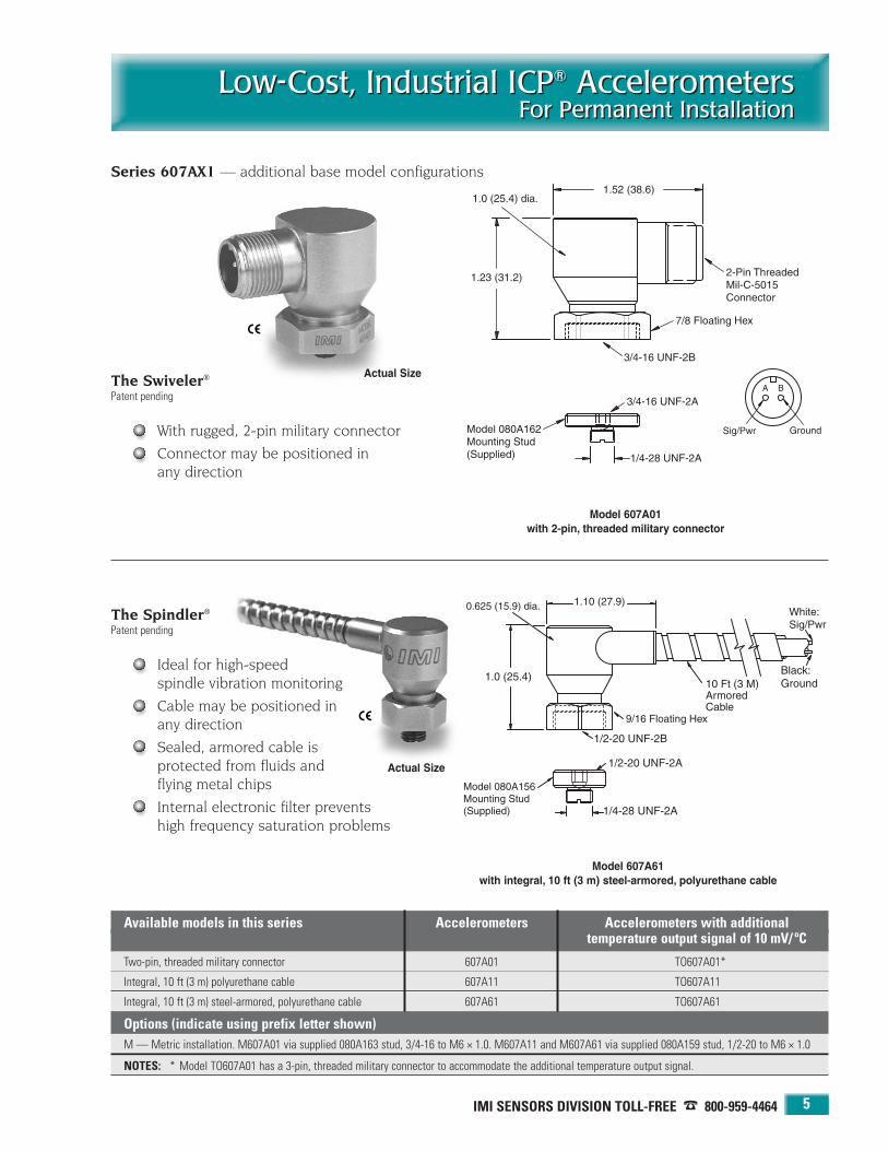
IMI SENSORS DIVISION TOLL-FREE � 800-959-4464
Low-Cost, Industrial ICP® AccelerometersFor Permanent Installation
Low-Cost, Industrial ICP® AccelerometersFor Permanent Installation
5
Series 607AX1 — additional base model configurations
Available models in this series Accelerometers Accelerometers with additional temperature output signal of 10 mV/ ºC
Two-pin, threaded military connector 607A01 TO607A01*
Integral, 10 ft (3 m) polyurethane cable 607A11 TO607A11
Integral, 10 ft (3 m) steel-armored, polyurethane cable 607A61 TO607A61
Options (indicate using prefix letter shown)M — Metric installation. M607A01 via supplied 080A163 stud, 3/4-16 to M6 × 1.0. M607A11 and M607A61 via supplied 080A159 stud, 1/2-20 to M6 × 1.0
NOTES: * Model TO607A01 has a 3-pin, threaded military connector to accommodate the additional temperature output signal.
Model 607A61with integral, 10 ft (3 m) steel-armored, polyurethane cable
Model 607A01with 2-pin, threaded military connector
Actual Size
Actual Size
The Spindler®
Patent pending
Ideal for high-speed spindle vibration monitoring
Cable may be positioned in any direction
Sealed, armored cable is protected from fluids and flying metal chips
Internal electronic filter prevents high frequency saturation problems
The Swiveler®
Patent pending
With rugged, 2-pin military connector
Connector may be positioned in any direction
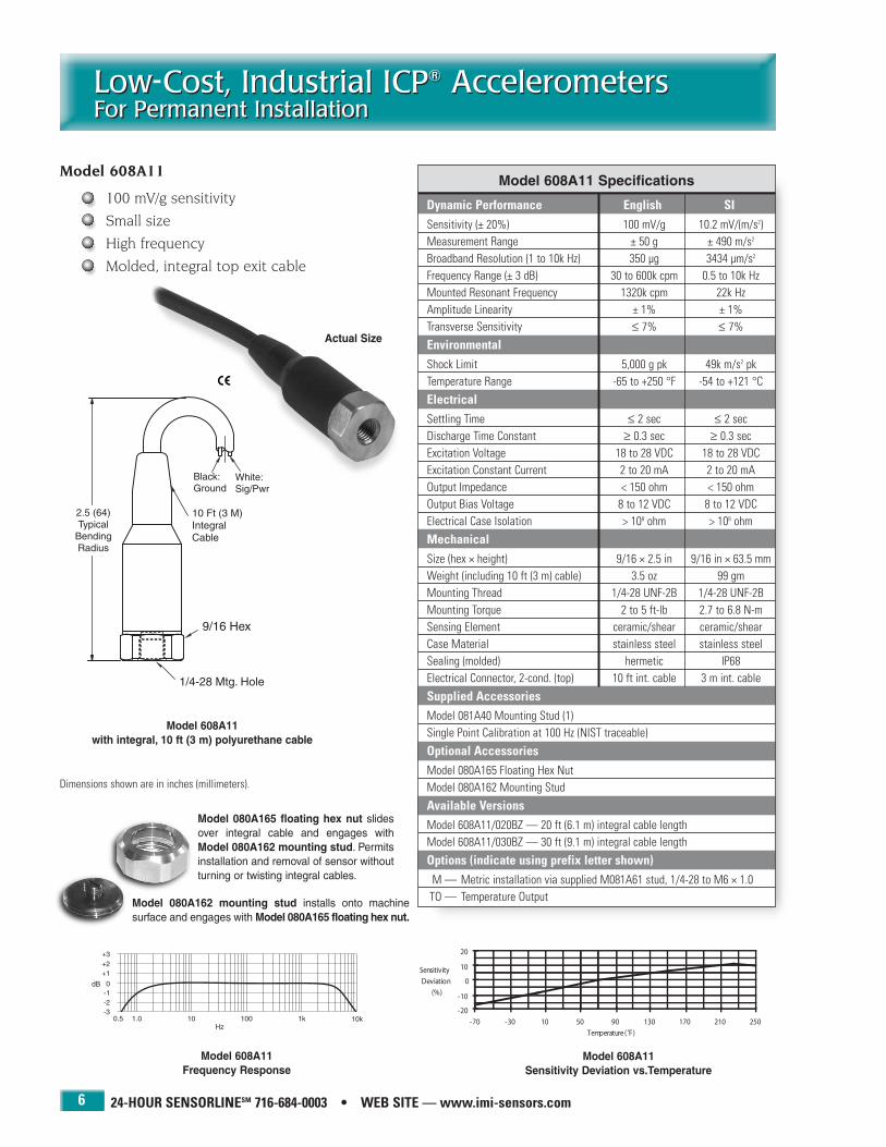
24-HOUR SENSORLINESM 716-684-0003 • WEB SITE — www.imi-sensors.com
Low Cost, Industrial ICP® AccelerometersFor Permanent InstallationLow-Cost, Industrial ICP® AccelerometersFor Permanent Installation
6
Model 608A11 with integral, 10 ft (3 m) polyurethane cable
Dimensions shown are in inches (millimeters).
Actual Size
Model 608A11 Specifications
Dynamic Performance English SISensitivity (± 20%) 100 mV/g 10.2 mV/(m/s2)Measurement Range ± 50 g ± 490 m/s2
Broadband Resolution (1 to 10k Hz) 350 µg 3434 µm/s2
Frequency Range (± 3 dB) 30 to 600k cpm 0.5 to 10k HzMounted Resonant Frequency 1320k cpm 22k HzAmplitude Linearity ± 1% ± 1%Transverse Sensitivity ≤ 7% ≤ 7%
EnvironmentalShock Limit 5,000 g pk 49k m/s2 pkTemperature Range -65 to +250 °F -54 to +121 °C
ElectricalSettling Time ≤ 2 sec ≤ 2 secDischarge Time Constant ≥ 0.3 sec ≥ 0.3 secExcitation Voltage 18 to 28 VDC 18 to 28 VDCExcitation Constant Current 2 to 20 mA 2 to 20 mAOutput Impedance < 150 ohm < 150 ohmOutput Bias Voltage 8 to 12 VDC 8 to 12 VDCElectrical Case Isolation > 108 ohm > 108 ohm
MechanicalSize (hex × height) 9/16 × 2.5 in 9/16 in × 63.5 mmWeight (including 10 ft (3 m) cable) 3.5 oz 99 gmMounting Thread 1/4-28 UNF-2B 1/4-28 UNF-2BMounting Torque 2 to 5 ft-lb 2.7 to 6.8 N-mSensing Element ceramic/shear ceramic/shearCase Material stainless steel stainless steelSealing (molded) hermetic IP68Electrical Connector, 2-cond. (top) 10 ft int. cable 3 m int. cable
Supplied AccessoriesModel 081A40 Mounting Stud (1)Single Point Calibration at 100 Hz (NIST traceable)
Optional AccessoriesModel 080A165 Floating Hex NutModel 080A162 Mounting Stud
Available VersionsModel 608A11/020BZ — 20 ft (6.1 m) integral cable lengthModel 608A11/030BZ — 30 ft (9.1 m) integral cable length
Options (indicate using prefix letter shown)M — Metric installation via supplied M081A61 stud, 1/4-28 to M6 × 1.0TO — Temperature Output
Model 608A11 Sensitivity Deviation vs.Temperature
Model 608A11 Frequency Response
Model 080A165 floating hex nut slidesover integral cable and engages withModel 080A162 mounting stud. Permitsinstallation and removal of sensor withoutturning or twisting integral cables.
Model 080A162 mounting stud installs onto machine surface and engages with Model 080A165 floating hex nut.
Model 608A11
100 mV/g sensitivity
Small size
High frequency
Molded, integral top exit cable
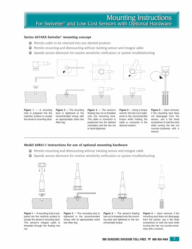
IMI SENSORS DIVISION TOLL-FREE � 800-959-4464
Mounting InstructionsFor Swiveler® and Low Cost Sensors with Optional Hardware
Mounting InstructionsFor Swiveler® and Low Cost Sensors with Optional Hardware
7
Series 607AXX Swiveler® mounting concept
Permits cable to be oriented into any desired position
Permits mounting and dismounting without twisting sensor and integral cable
Speeds sensor dismount for routine sensitivity verification or system troubleshooting
Model 608A11 instructions for use of optional mounting hardware
Permits mounting and dismounting without twisting sensor and integral cable
Speeds sensor dismount for routine sensitivity verification or system troubleshooting
Figure 1 — A mountinghole is prepared into themachine surface to acceptthe sensor’s mounting stud.
Figure 2 — The mountingstud is tightened to the recommended torque withan appropriately sized hexAllen key.
Figure 3 — The sensor’sfloating hex nut is threadedonto the mounting stud.The cable or connector ispositioned into the desiredorientation and the hex nutis hand-tightened.
Figure 4 — Using a torquewrench, the hex nut is tight-ened to the recommendedtorque while holding thecable or connector in thedesired location.
Figure 5 — Upon removal,if the mounting stud doesnot disengage from thesensor, use a flat headscrewdriver to hold the studwhile turning the hex nutcounter-clockwise with awrench.
Figure 1 — A mounting hole is pre-pared into the machine surface toaccept the sensor’s mounting stud.The sensor’s integral cable isthreaded through the floating hexnut.
Figure 2 — The mounting stud istightened to the recommendedtorque with an appropriately sizedhex Allen key.
Figure 3 — The sensor’s floatinghex nut is threaded onto the mount-ing stud and tightened to the rec-ommended torque.
Figure 4 — Upon removal, if themounting stud does not disengagefrom the sensor, use a flat headscrewdriver to hold the stud whileturning the hex nut counter-clock-wise with a wrench.

24-HOUR SENSORLINESM 716-684-0003 • WEB SITE — www.imi-sensors.com
Low-Cost, Industrial ICP® AccelerometersFor Permanent InstallationLow-Cost, Industrial ICP® AccelerometersFor Permanent Installation
8
Series 606BX1
100 mV/g sensitivity
Ring style, side exit connectors
Connector may be positioned in anydirection
Model 606B01 with 2-pin, threaded military connector
Dimensions shown are in inches (millimeters).
Model 606B01 Specifications
Dynamic Performance English SISensitivity (± 20%) 100 mV/g 10.2 mV/(m/s2)Measurement Range ± 50 g ± 490 m/s2
Broadband Resolution (1 to 10k Hz) 350 µg 3434 µm/s2
Frequency Range (± 3 dB) 30 to 600k cpm 0.5 to 10k HzMounted Resonant Frequency 1500k cpm 25k HzAmplitude Linearity ± 1% ± 1%Transverse Sensitivity ≤ 7% ≤ 7%
EnvironmentalShock Limit 5,000 g pk 49k m/s2 pkTemperature Range -65 to +250 °F -54 to +121 °C
ElectricalSettling Time ≤ 2.0 sec ≤ 2.0 secDischarge Time Constant ≥ 0.3 sec ≥ 0.3 secExcitation Voltage 18 to 28 VDC 18 to 28 VDCExcitation Constant Current 2 to 20 mA 2 to 20 mAOutput Impedance < 150 ohm < 150 ohmOutput Bias Voltage 8 to 12 VDC 8 to 12 VDCElectrical Case Isolation > 108 ohm > 108 ohm
MechanicalSize (diameter × height) 1.38 × 1.0 in 35.1 × 25.4 mmWeight 4.4 oz 124 gmMounting Thread 1/4-28 UNF-2A 1/4-28 UNF-2AMounting Torque 2 to 5 ft-lb 2.7 to 6.8 N-mSensing Element ceramic/shear ceramic/shearCase Material stainless steel stainless steelSealing (welded) hermetic IP68Electrical Connector, 2-pin (side) MIL-C-5015 MIL-C-5015
Supplied AccessoriesModel 081A68 Mounting Bolt (1)Single Point Calibration at 100 Hz (NIST traceable)
Options (indicate using prefix letter shown)M — Metric installation via supplied M081A68 bolt, M6 × 1.0 thread
Series 606BX1 Sensitivity Deviation vs. Temperature
Series 606BX1 Frequency Response
Actual Size

IMI SENSORS DIVISION TOLL-FREE � 800-959-4464
Low Cost, Industrial ICP® AccelerometersFor Permanent Installation
Low-Cost, Industrial ICP® AccelerometersFor Permanent Installation
9
Series 606BX1 — additional base model configurations
Model 606B31with 3-pin, bayonet military connector
Model 606B11 with integral, 10 ft (3 m) polyurethane cable
Model 606B21 with integral, 10 ft (3 m) Teflon cable
Model 606B61 with integral, 10 ft (3 m) steel-armored, polyurethane cable
Available models in this series AccelerometersTwo-pin, threaded military connector 606B01
Integral, 10 ft (3 m) polyurethane cable 606B11
Integral, 10 ft (3 m) Teflon cable 606B21
Three-pin, bayonet military connector 606B31
Integral, 10 ft (3 m) steel-armored, polyurethane cable 606B61
Options (indicate using prefix letter shown)M — Metric installation via supplied M081A68 bolt, M6 × 1.0 thread

24-HOUR SENSORLINESM 716-684-0003 • WEB SITE — www.imi-sensors.com
Low-Cost, Industrial ICP® AccelerometersFor Permanent InstallationLow-Cost, Industrial ICP® AccelerometersFor Permanent Installation
10
Series 601AX1 Series 602CX1 Series 627AX1
Dynamic Performance English SI English SI English SISensitivity 100 mV/g (± 20%) 10.2 mV/(m/s2) 100 mV/g (± 20%) 10.2 mV/(m/s2) 100 mV/g (± 15%) 10.2 mV/(m/s2)Measurement Range ± 50 g ± 490 m/s2 ± 50 g ± 490 m/s2 ± 50 g ± 490 m/s2
Broadband Resolution (1 to 10k Hz) 50 µg 491 µm/s2 350 µg 3434 µm/s2 1000 µg 9800 µm/s2
Frequency Range (± 3 dB) 16 to 600k cpm 0.27 to 10k Hz 30 to 480k cpm 0.5 to 8000 Hz 20 to 600k cpm 0.33 to 10k HzMounted Resonant Frequency 960k cpm 16k Hz 1500k cpm 25k Hz 1080k cpm 18k HzAmplitude Linearity ± 1% ± 1% ± 1% ± 1% ± 1% ± 1%Transverse Sensitivity ≤ 7% ≤ 7% ≤ 7% ≤ 7% ≤ 5% ≤ 5%
EnvironmentalShock Limit 5,000 g pk 49k m/s2 pk 5,000 g pk 49k m/s2 pk 5,000 g pk 49k m/s2 pkTemperature Range -65 to +250 °F -54 to +121 °C -65 to +250 °F -54 to +121 °C -65 to +250 °F -54 to +121 °C
ElectricalSettling Time ≤ 4.0 sec ≤ 4.0 sec ≤ 2.0 sec ≤ 2.0 sec ≤ 10 sec ≤ 10 secDischarge Time Constant ≥ 0.6 sec ≥ 0.6 sec ≥ 0.3 sec ≥ 0.3 sec ≥ 0.5 sec ≥ 0.5 secExcitation Voltage 18 to 28 VDC 18 to 28 VDC 18 to 28 VDC 18 to 28 VDC 18 to 28 VDC 18 to 28 VDCExcitation Constant Current 2 to 20 mA 2 to 20 mA 2 to 20 mA 2 to 20 mA 2 to 20 mA 2 to 20 mAOutput Impedance < 150 ohm < 150 ohm < 150 ohm < 150 ohm < 100 ohm < 100 ohmOutput Bias Voltage 8 to 12 VDC 8 to 12 VDC 8 to 12 VDC 8 to 12 VDC 8 to 12 VDC 8 to 12 VDCElectrical Case Isolation > 108 ohm > 108 ohm > 108 ohm > 108 ohm > 108 ohm > 108 ohmElectrical Protection — — — — RFI/ESD RFI/ESD
MechanicalSize 7/8 hex × 1.94 in 7/8 in hex × 49.3 mm 1.65×0.74×0.85 in 41.9×18.8×21.6 mm 7/8 hex × 2.06 in 7/8 in hex × 52.3 mmWeight 2.8 oz 80 gm 2.75 oz 78 gm 3.3 oz 94 gmMounting Thread 1/4-28 UNF-2B 1/4-28 UNF-2B 1/4-28 UNF-2A 1/4-28 UNF-2A 1/4-28 UNF-2B 1/4-28 UNF-2BMounting Torque 2 to 5 ft-lb 2.7 to 6.8 N-m 2 to 5 ft-lb 2.7 to 6.8 N-m 2 to 5 ft-lb 2.7 to 6.8 N-mSensing Element ceramic/shear ceramic/shear ceramic/shear ceramic/shear quartz/shear quartz/shearCase Material stainless steel stainless steel stainless steel stainless steel stainless steel stainless steelSealing (welded) hermetic IP68 hermetic IP68 hermetic IP68Electrical Connector, 2-pin MIL-C-5015 (top) MIL-C-5015 (top) MIL-C-5015 (side) MIL-C-5015 (side) MIL-C-5015 (top) MIL-C-5015 (top)
Supplied AccessoriesMounting Stud or Bolt Model 081A40 (1) Model 081A97 (1) Model 081A40 (1)Calibration (NIST traceable) Single Point at 100 Hz Single Point at 100 Hz Single Point at 100 Hz
Available VersionsTwo-pin, Threaded Military Connector 601A01 602C01 627A01Integral, 10 ft (3 m) Polyurethane Cable 601A11 602C11 627A11Integral, 10 ft (3 m) Teflon Cable 601A21 602C21 627A21Three-pin, Bayonet Military Connector 601A31 602C31 627A31Integral, 10 ft (3 m) Steel-Armored Cable 601A61 602C61 627A61Two-socket Terminal Block 601A71 — 627A71
Options (indicate using prefix letter shown)Metric Installation M* M† M*Temperature Output TO§ TO‡ —
NOTES: * via supplied M081A61 stud, 1/4-28 to M6 × 1.0 † via supplied M081A97 bolt, M6 × 1.0 thread§ TO601A01, TO601A11, TO601A61 versions only‡ available as alternate configurations: TO602A01, TO602A11, and TO602A61, specifications may vary — consult factory
AdditionalLow-Cost,Industrial ICP®
Accelerometers
QuartzElement
Through-holeMount
Low Noise
Dimensional drawings on page 18

11
PCB 716-684-0001 IMI Sensors Division toll-free 800-959-4464 Fax 716-684-3823 E-mail [email protected] Web site www.imi-sensors.com
Interface directly with vibration data collectors
Ideal for FFT analysis of vibration frequencies
Measurements for machinery diagnostics
Versions with velocity output, temperature output, and hazardous area approvals
Precision industrial ICP® accelerometers are recommendedfor route-based vibration data collection and quantitativediagnostic measurements on industrial machinery. Thesesensors are directly compatible with most commerciallyavailable vibration data collectors and FFT analyzers thatsupply excitation power for ICP® sensors.
These precision, shear-structured sensors offer tighter sensitivity tolerances than low-cost series units and are supported with full NIST traceable calibration data thatencompasses an extensive frequency range. All units are laserwelded and leak tested to ensure a true hermetic seal. Shockprotection to 5000 g (49k m/s2) guards against damage due toaccidental overloads.
A host of available options including velocity output, temperature output, and hazardous area approvals adapt theunits for virtually any machinery vibration monitoringrequirement.
Precision Industrial ICP® Accelerometers
For Route-Based Measurements
Precision Industrial ICP® Accelerometers
For Route-Based Measurements

24-HOUR SENSORLINESM 716-684-0003 • WEB SITE — www.imi-sensors.com
Precision Industrial ICP® AccelerometersFor Route-Based MeasurementsPrecision Industrial ICP® AccelerometersFor Route-Based Measurements
12
Series 622AX1
100 mV/g sensitivity
Top exit connectors
50 micro g resolution
Model 622A01 with 2-pin, threaded military connector
Dimensions shown are in inches (millimeters).
Actual Size
Model 622A01 Specifications
Dynamic Performance English SISensitivity (± 5%) 100 mV/g 10.2 mV/(m/s2)Measurement Range ± 50 g ± 490 m/s2
Broadband Resolution (1 to 10k Hz) 50 µg 491 µm/s2
Frequency Range: (± 5%) 35 to 240k cpm 0.58 to 4000 Hz(± 10%) 25 to 300k cpm 0.42 to 5000 Hz(± 3 dB) 12 to 600k cpm 0.2 to 10k Hz
Mounted Resonant Frequency 1200k cpm 20k HzAmplitude Linearity ± 1% ± 1%Transverse Sensitivity ≤ 5% ≤ 5%
EnvironmentalShock Limit 5,000 g pk 49k m/s2 pkTemperature Range -65 to +250 °F -54 to +121 °C
ElectricalSettling Time ≤ 5 sec ≤ 5 secDischarge Time Constant ≥ 0.8 sec ≥ 0.8 secExcitation Voltage 18 to 28 VDC 18 to 28 VDCExcitation Constant Current 2 to 20 mA 2 to 20 mAOutput Impedance < 100 ohm < 100 ohmOutput Bias Voltage 8 to 12 VDC 8 to 12 VDCElectrical Case Isolation > 108 ohm > 108 ohmElectrical Protection RFI/ESD RFI/ESD
MechanicalSize (hex × height) 7/8 × 2.06 in 7/8 in × 52.3 mmWeight 3.3 oz 94 gmMounting Thread 1/4-28 UNF-2B 1/4-28 UNF-2BMounting Torque 2 to 5 ft-lb 2.7 to 6.8 N-mSensing Element ceramic/shear ceramic/shearCase Material stainless steel stainless steelSealing (welded) hermetic IP68Electrical Connector, 2-pin (top) MIL-C-5015 MIL-C-5015
Supplied AccessoriesModel 081A40 Mounting Stud (1)Full Calibration from 600 to 240k cpm (NIST traceable)
Options (indicate using prefix letter shown)CS, EX, MS, MX, FM — Intrinsically SafeHT — High Temperature operation (see pages 47-52)LB — Low Bias electronics for operation from 12 to 28 VDC excitation voltageM — Metric installation via supplied M081A61 stud, 1/4-28 to M6 × 1.0TO — Temperature OutputVO — Velocity Output (see pages 17 and 18 for specifications and drawings)
Series 622AX1 Sensitivity Deviation vs. Temperature
Series 622AX1 Frequency Response

Model 622A11with integral, 10 ft (3 m) polyurethane cable
Model 622A21with integral, 10 ft (3 m) Teflon cable
IMI SENSORS DIVISION TOLL-FREE � 800-959-4464
Precision Industrial ICP® AccelerometersFor Route-Based Measurements
Precision Industrial ICP® AccelerometersFor Route-Based Measurements
13
Series 622AX1 — additional base model configurations
Available models in this series Accelerometers Accelerometers with Intrinsically Safe Velocity Intrinsically SafeTemperature Output Accelerometers§ Sensors Velocity Sensors†§
Two-pin, threaded military connector 622A01 TO622A01* CS, EX, MS, MX, or FM622A01§ VO622A01† CS, EX, MX, or FMVO622A01†§
Integral, 10 ft (3 m) polyurethane cable 622A11 TO622A11 CS, EX, MS, MX, or FM622A11§ VO622A11† CS, EX, MX, or FMVO622A11†§
Integral, 10 ft (3 m) Teflon cable 622A21 — — — VO622A21†
Three-pin, bayonet military connector 622A31 — CS, EX, MS or FM622A31§ VO622A31† —Integral, 10 ft (3 m) steel-armored cable 622A61 TO622A61 — VO622A61† —
Options (indicate using prefix letter shown)LB — Low Bias electronics for operation from 12 to 28 VDC excitation voltage
M — Metric installation via supplied M081A61 stud, 1/4-28 to M6 × 1.0
NOTES: * Model TO622A01 features a 3-pin, threaded military connector to accommodate the additional temperature output signal.† See pages 17 and 18 for Velocity Sensor specifications and drawings.§ Intrinsically safe accelerometers and velocity sensors require the use of an intrinsic safety barrier. See pages 83 to 86 for details.
Available approvals are:CS — Canadian Standards, EX — CENELEC, MS — Mine Safety Administration, MX — CENELEC for mining, FM — Factory Mutual.
Model 622A31 with 3-pin, bayonet military connector
Model 622A61 with integral, 10 ft (3 m) steel-armored, polyurethane cable

24-HOUR SENSORLINESM 716-684-0003 • WEB SITE — www.imi-sensors.com
Precision Industrial ICP® AccelerometersFor Route-Based MeasurementsPrecision Industrial ICP® AccelerometersFor Route-Based Measurements
14
Series 625BX1
100 mV/g sensitivity
Ring style, side exit connectors
Connector may be positioned in anydirection
50 micro g resolution
Model 625B01 with 2-pin, threaded military connector
Dimensions shown are in inches (millimeters).
Model 625B01 Specifications
Dynamic Performance English SISensitivity (± 5%) 100 mV/g 10.2 mV/(m/s2)Measurement Range ± 50 g ± 490 m/s2
Broadband Resolution (1 to 10k Hz) 50 µg 491 µm/s2
Frequency Range: (± 5%) 30 to 390k cpm 0.5- 6500 Hz(± 10%) 22 to 450k cpm 0.37 to 7500 Hz(± 3 dB) 12 to 630k cpm 0.2 to 10.5k Hz
Mounted Resonant Frequency 1500k cpm 25k HzAmplitude Linearity ± 1% ± 1%Transverse Sensitivity ≤ 5% ≤ 5%
EnvironmentalShock Limit 5,000 g pk 49k m/s2 pkTemperature Range -65 to +250 °F -54 to +121 °C
ElectricalSettling Time ≤ 8.0 sec ≤ 8.0 secDischarge Time Constant ≥ 1.0 sec ≥ 1.0 secExcitation Voltage 18 to 28 VDC 18 to 28 VDCExcitation Constant Current 2 to 20 mA 2 to 20 mAOutput Impedance < 100 ohm < 100 ohmOutput Bias Voltage 8 to 12 VDC 8 to 12 VDCElectrical Case Isolation > 108 ohm > 108 ohm
MechanicalSize (diameter × height) 1.38 × 1.13 in 35.1 × 28.7 mmWeight 5.1 oz 145 gmMounting Thread 1/4-28 UNF-2A 1/4-28 UNF-2AMounting Torque 2 to 5 ft-lb 2.7 to 6.8 N-mSensing Element ceramic/shear ceramic/shearCase Material stainless steel stainless steelSealing (welded) hermetic IP68Electrical Connector, 2-pin (side) MIL-C-5015 MIL-C-5015
Supplied AccessoriesModel 081A73 Mounting Bolt (1)Model 080B45 Thermal Boot (1)Full Calibration from 600 to 390k cpm (NIST traceable)
Options (indicate using prefix letter shown)CS, FM — Intrinsically SafeLB — Low Bias electronics for operation from 12 to 28 VDC excitation voltageM — Metric installation via supplied M081A73 bolt, M6 × 1.0 threadTO — Temperature OutputVO — Velocity Output available on alternate configuration, Model VO625A01.
See pages 17 and 18 for specifications and drawings.
Actual Size
Series 625BX1 Sensitivity Deviation vs. Temperature
Series 625BX1 Frequency Response

IMI SENSORS DIVISION TOLL-FREE � 800-959-4464
Precision Industrial ICP® AccelerometersFor Route-Based Measurements
Precision Industrial ICP® AccelerometersFor Route-Based Measurements
15
Available models in this series Accelerometers Accelerometers with Intrinsically Safe Velocityadditional temperature Accelerometers† Sensors
output signal of 10 mV/°C
Two-pin, threaded military connector 625B01 TO625B01* CS or FM625B01 VO625A01§
Integral, 10 ft (3 m) polyurethane cable 625B11 TO625B11 — VO625A11§
Integral, 10 ft (3 m) Teflon cable 625B21 — — VO625A21§
Three pin, bayonet military connector 625B31 — — VO625A31§
Integral, 10 ft (3 m) steel-armored cable 625B61 TO625B61 — VO625A61§
Options (indicate using prefix letter shown)LB — Low Bias electronics for operation from 12 to 28 VDC excitation voltage
M — Metric installation via supplied M081A73 bolt, M6 × 1.0 thread
NOTES: * Model TO625B01 features a 3-pin, threaded military connector to accommodate the additional temperature output signal.† Intrinsically safe accelerometers and velocity sensors require the use of an intrinsic safety barrier. See pages 83 to 86 for details.
Available approvals are: CS — Canadian Standards, FM — Factory Mutual.§ Alternate Configuration. See pages 17 and 18 for Velocity Sensor specifications and drawings
Additional Versions (see page 16): 10 mV/g — Series 625BX0
Series 625BX1 — additional base model configurations
Model 625B31 with 3-pin, bayonet military connector
Model 625B11 with integral, 10 ft (3 m) polyurethane cable
Model 625B21 with integral, 10 ft (3 m) Teflon cable
Model 625B61 with integral, 10 ft (3 m) steel-armored, polyurethane cable
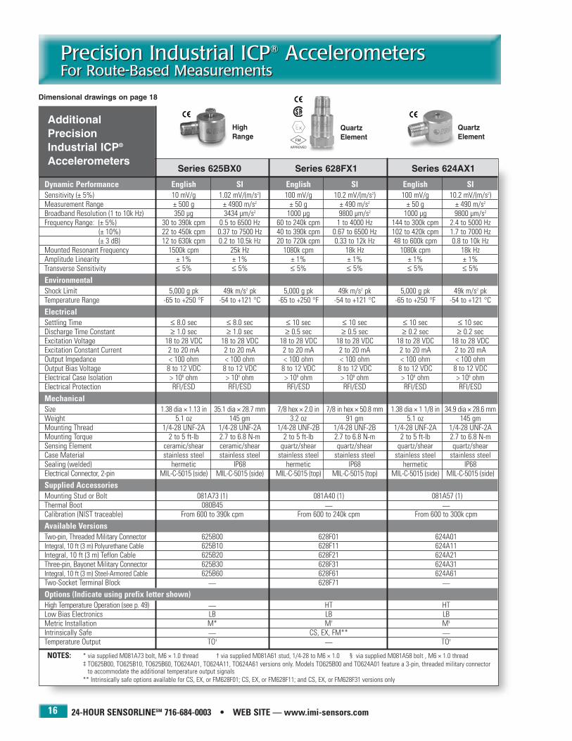
24-HOUR SENSORLINESM 716-684-0003 • WEB SITE — www.imi-sensors.com
Precision Industrial ICP® AccelerometersFor Route-Based MeasurementsPrecision Industrial ICP® AccelerometersFor Route-Based Measurements
16
Series 625BX0 Series 628FX1 Series 624AX1
Dynamic Performance English SI English SI English SISensitivity (± 5%) 10 mV/g 1.02 mV/(m/s2) 100 mV/g 10.2 mV/(m/s2) 100 mV/g 10.2 mV/(m/s2)Measurement Range ± 500 g ± 4900 m/s2 ± 50 g ± 490 m/s2 ± 50 g ± 490 m/s2
Broadband Resolution (1 to 10k Hz) 350 µg 3434 µm/s2 1000 µg 9800 µm/s2 1000 µg 9800 µm/s2
Frequency Range: (± 5%) 30 to 390k cpm 0.5 to 6500 Hz 60 to 240k cpm 1 to 4000 Hz 144 to 300k cpm 2.4 to 5000 Hz(± 10%) 22 to 450k cpm 0.37 to 7500 Hz 40 to 390k cpm 0.67 to 6500 Hz 102 to 420k cpm 1.7 to 7000 Hz(± 3 dB) 12 to 630k cpm 0.2 to 10.5k Hz 20 to 720k cpm 0.33 to 12k Hz 48 to 600k cpm 0.8 to 10k Hz
Mounted Resonant Frequency 1500k cpm 25k Hz 1080k cpm 18k Hz 1080k cpm 18k HzAmplitude Linearity ± 1% ± 1% ± 1% ± 1% ± 1% ± 1%Transverse Sensitivity ≤ 5% ≤ 5% ≤ 5% ≤ 5% ≤ 5% ≤ 5%
EnvironmentalShock Limit 5,000 g pk 49k m/s2 pk 5,000 g pk 49k m/s2 pk 5,000 g pk 49k m/s2 pkTemperature Range -65 to +250 °F -54 to +121 °C -65 to +250 °F -54 to +121 °C -65 to +250 °F -54 to +121 °C
ElectricalSettling Time ≤ 8.0 sec ≤ 8.0 sec ≤ 10 sec ≤ 10 sec ≤ 10 sec ≤ 10 secDischarge Time Constant ≥ 1.0 sec ≥ 1.0 sec ≥ 0.5 sec ≥ 0.5 sec ≥ 0.2 sec ≥ 0.2 secExcitation Voltage 18 to 28 VDC 18 to 28 VDC 18 to 28 VDC 18 to 28 VDC 18 to 28 VDC 18 to 28 VDCExcitation Constant Current 2 to 20 mA 2 to 20 mA 2 to 20 mA 2 to 20 mA 2 to 20 mA 2 to 20 mAOutput Impedance < 100 ohm < 100 ohm < 100 ohm < 100 ohm < 100 ohm < 100 ohmOutput Bias Voltage 8 to 12 VDC 8 to 12 VDC 8 to 12 VDC 8 to 12 VDC 8 to 12 VDC 8 to 12 VDCElectrical Case Isolation > 108 ohm > 108 ohm > 108 ohm > 108 ohm > 108 ohm > 108 ohmElectrical Protection RFI/ESD RFI/ESD RFI/ESD RFI/ESD RFI/ESD RFI/ESD
MechanicalSize 1.38 dia × 1.13 in 35.1 dia × 28.7 mm 7/8 hex × 2.0 in 7/8 in hex × 50.8 mm 1.38 dia × 1 1/8 in 34.9 dia × 28.6 mmWeight 5.1 oz 145 gm 3.2 oz 91 gm 5.1 oz 145 gmMounting Thread 1/4-28 UNF-2A 1/4-28 UNF-2A 1/4-28 UNF-2B 1/4-28 UNF-2B 1/4-28 UNF-2A 1/4-28 UNF-2AMounting Torque 2 to 5 ft-lb 2.7 to 6.8 N-m 2 to 5 ft-lb 2.7 to 6.8 N-m 2 to 5 ft-lb 2.7 to 6.8 N-mSensing Element ceramic/shear ceramic/shear quartz/shear quartz/shear quartz/shear quartz/shearCase Material stainless steel stainless steel stainless steel stainless steel stainless steel stainless steelSealing (welded) hermetic IP68 hermetic IP68 hermetic IP68Electrical Connector, 2-pin MIL-C-5015 (side) MIL-C-5015 (side) MIL-C-5015 (top) MIL-C-5015 (top) MIL-C-5015 (side) MIL-C-5015 (side)
Supplied AccessoriesMounting Stud or Bolt 081A73 (1) 081A40 (1) 081A57 (1)Thermal Boot 080B45 — —Calibration (NIST traceable) From 600 to 390k cpm From 600 to 240k cpm From 600 to 300k cpm
Available VersionsTwo-pin, Threaded Military Connector 625B00 628F01 624A01Integral, 10 ft (3 m) Polyurethane Cable 625B10 628F11 624A11Integral, 10 ft (3 m) Teflon Cable 625B20 628F21 624A21Three-pin, Bayonet Military Connector 625B30 628F31 624A31Integral, 10 ft (3 m) Steel-Armored Cable 625B60 628F61 624A61Two-Socket Terminal Block — 628F71 —Options (Indicate using prefix letter shown)High Temperature Operation (see p. 49) — HT HTLow Bias Electronics LB LB LBMetric Installation M* M† M§
Intrinsically Safe — CS, EX, FM** —Temperature Output TO‡ — TO‡
NOTES: * via supplied M081A73 bolt, M6 × 1.0 thread † via supplied M081A61 stud, 1/4-28 to M6 × 1.0 § via supplied M081A58 bolt , M6 × 1.0 thread‡ TO625B00, TO625B10, TO625B60, TO624A01, TO624A11, TO624A61 versions only. Models TO625B00 and TO624A01 feature a 3-pin, threaded military connector
to accommodate the additional temperature output signals** Intrinsically safe options available for CS, EX, or FM628F01; CS, EX, or FM628F11; and CS, EX, or FM628F31 versions only
AdditionalPrecisionIndustrial ICP®
Accelerometers
Quartz Element
Quartz Element
High Range
Dimensional drawings on page 18
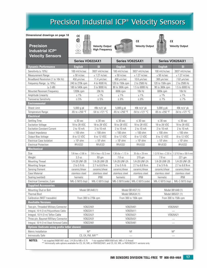
IMI SENSORS DIVISION TOLL-FREE � 800-959-4464
Precision Industrial ICP® Velocity SensorsPrecision Industrial ICP® Velocity Sensors
17
Dimensional drawings on page 18
Series VO622AX1 Series VO625AX1 Series VO626AX1
Dynamic Performance English SI English SI English SISensitivity (± 10%) 100 mV/in/sec 3937 mV/m/sec 100 mV/in/sec 3937 mV/m/sec 100 mV/in/sec 3937 mV/m/secMeasurement Range ± 50 in/sec ± 1.27 m/sec ± 50 in/sec ± 1.27 m/sec ± 50 in/sec ± 1.27 m/secBroadband Resolution (1 to 10k Hz) 450 µin/sec 11.4 µm/sec 400 µin/sec 10.6 µm/sec 300 µin/sec 7.62 µm/secFrequency Range: (± 10%) 240 to 270k cpm 4 to 4500 Hz 120 to 150k cpm 2 to 2500 Hz 120 to 150k cpm 2 to 2500 Hz
(± 3 dB) 180 to 540k cpm 3 to 9000 Hz 90 to 360k cpm 1.5 to 6000 Hz 90 to 360k cpm 1.5 to 6000 HzMounted Resonant Frequency 1200k cpm 20k Hz 600k cpm 10k Hz 600k cpm 10k HzAmplitude Linearity ± 1% ± 1% ± 1% ± 1% ± 1% ± 1%Transverse Sensitivity ≤ 5% ≤ 5% ≤ 8% ≤ 8% ≤ 7% ≤ 7%
EnvironmentalShock Limit 5,000 g pk 49k m/s2 pk 5,000 g pk 49k m/s2 pk 5,000 g pk 49k m/s2 pkTemperature Range -65 to +250 °F -54 to +121 °C -65 to +250 °F -54 to +121 °C -65 to +250 °F -54 to +121 °C
ElectricalSettling Time ≤ 30 sec ≤ 30 sec ≤ 30 sec ≤ 30 sec ≤ 30 sec ≤ 30 secExcitation Voltage 18 to 28 VDC 18 to 28 VDC 18 to 28 VDC 18 to 28 VDC 18 to 28 VDC 18 to 28 VDCExcitation Constant Current 2 to 10 mA 2 to 10 mA 2 to 10 mA 2 to 10 mA 2 to 10 mA 2 to 10 mAOutput Impedance < 100 ohm < 100 ohm < 100 ohm < 100 ohm < 100 ohm < 100 ohmOutput Bias Voltage 8 to 12 VDC 8 to 12 VDC 8 to 12 VDC 8 to 12 VDC 8 to 12 VDC 8 to 12 VDCElectrical Case Isolation > 108 ohm > 108 ohm > 108 ohm > 108 ohm > 108 ohm > 108 ohmElectrical Protection RFI/ESD RFI/ESD RFI/ESD RFI/ESD RFI/ESD RFI/ESD
MechanicalSize 7/8 hex × 2.06 in 7/8 in hex × 52.3 mm 1.38 dia × 1.13 in 35 dia × 29 mm 1-3/16 hex × 2.30 in 1-3/16 hex × 58.4 mm
Weight 3.3 oz 93 gm 7.6 oz 215 gm 7.8 oz 221 gmMounting Thread 1/4-28 UNF-2B 1/4-28 UNF-2B 1/4-28 UNF-2A 1/4-28 UNF-2A 1/4-28 UNF-2B 1/4-28 UNF-2BMounting Torque 2 to 5 ft-lb 2.7 to 6.8 N-m 2 to 5 ft-lb 2.7 to 6.8 N-m 2 to 5 ft-lb 2.7 to 6.8 N-mSensing Element ceramic/shear ceramic/shear ceramic/shear ceramic/shear ceramic/shear ceramic/shearCase Material stainless steel stainless steel stainless steel stainless steel stainless steel stainless steelSealing (welded) hermetic IP68 hermetic IP68 hermetic IP68Electrical Connector, 2-pin MIL-C-5015 (top) MIL-C-5015 (top) MIL-C-5015 (side) MIL-C-5015 (side) MIL-C-5015 (top) MIL-C-5015 (top)
Supplied AccessoriesMounting Stud or Bolt Model 081A40 (1) Model 081A57 (1) Model 081A40 (1)Thermal Boot — Model 085A34 (1) Model 085A31 (1)Calibration (NIST traceable) From 300 to 270k cpm From 300 to 150k cpm From 300 to 150k cpm
Available VersionsTwo-pin, Threaded Military Connector VO622A01 VO625A01 VO626A01Integral, 10 ft (3 m) Polyurethane Cable VO622A11 VO625A11 —Integral, 10 ft (3 m) Teflon Cable VO622A21 VO625A21 VO626A21Three-pin, Bayonet Military Connector VO622A31 VO625A31 —Integral, 10 ft (3 m) Steel-Armored Cable VO622A61 VO625A61 —Options (Indicate using prefix letter shown)Metric Installation M* M† M*Intrinsically Safe CS, EX, FM, MX** — —
NOTES: * via supplied M081A61 stud, 1/4-28 to M6 x 0.75 † via supplied M081A58 bolt, M6 x 1.0 thread** Intrinsically safe options available for CS, EX, MX, or FMVO622A01; and CS, EX, MX, or FMVO622A11 versions only
PrecisionIndustrial ICP®
Velocity Sensors
Velocity OutputHigh Frequency
Velocity Output Velocity Output

24-HOUR SENSORLINESM 716-684-0003 • WEB SITE — www.imi-sensors.com
Outline DrawingsOutline Drawings
18
Outline drawings for additional precision sensors
All Drawings Shown at 1/2 Actual Size
Outline drawings for additional low-cost sensors
All Drawings Shown at 1/2 Actual Size
Dimensions shown are in inches (millimeters).
Model 625B00 with 2-pin, threaded military connector
Model 628F01with 2-pin, threaded military connector
Model 624A01with 2-pin, threaded military connector
Model VO622A01with 2-pin, threaded military connector
Model VO625A01with 2-pin, threaded military connector
Model VO626A01with 2-pin, threaded military connector
Model 601A01with 2-pin, threaded military connector
Model 602C01with 2-pin, threaded military connector
Model 627A01with 2-pin, threaded military connector
Dimensions shown are in inches (millimeters).

High Frequency Industrial ICP® Accelerometers
High Frequency Industrial ICP® Accelerometers
19
PCB 716-684-0001 IMI Sensors Division toll-free 800-959-4464 Fax 716-684-3823 E-mail [email protected] Web site www.imi-sensors.com
Vibration measurements on highspeed rotating machinery
Gear mesh studies and diagnostics
Bearing monitoring
Small mechanisms
High-speed spindles
Successful vibration measurements begin with sensors thathave adequate capabilities for the requirement. If the sensor’s frequency response characteristics are inadequate,the user risks corrupted or insufficient data to achieve aproper analysis and diagnosis. For vibration monitoring, testing, and frequency analysis of high-speed rotatingmachinery, spindles, and gear mesh, it is imperative to utilizea sensor with a sufficient high frequency range to accuratelycapture the vibration signals within the bandwidth of interest.
These precision, high frequency ICP® accelerometers meetthe requirements of high frequency signal analysis. Miniaturesized units are also suitable for vibration measurements onsmall mechanisms where sensor size and weight becomeimportant factors.

24-HOUR SENSORLINESM 716-684-0003 • WEB SITE — www.imi-sensors.com
High FrequencyIndustrial ICP® AccelerometersHigh FrequencyIndustrial ICP® Accelerometers
20
Series 623CX0
10 mV/g sensitivity
Small size
High frequency
Top exit connectors
Model 623C00with 2-pin, threaded military connector
Dimensions shown are in inches (millimeters).
Actual Size
Model 623C00 Specifications
Dynamic Performance English SISensitivity (± 5%) 10 mV/g 1 mV/(m/s2)Measurement Range ± 500 g ± 4905 m/s2
Broadband Resolution (1 to 10k Hz) 300 µg 2943 µm/s2
Frequency Range: (± 5%) 144 to 480k cpm 2.4 to 8000 Hz(± 10%) 102 to 600k cpm 1.7 to 10k Hz(± 3 dB) 48 to 900k cpm 0.8 to 15k Hz
Mounted Resonant Frequency 2400k cpm 40k HzAmplitude Linearity ± 1% ± 1%Transverse Sensitivity ≤ 5% ≤ 5%
EnvironmentalShock Limit 5,000 g pk 49k m/s2 pkTemperature Range -65 to +250 °F -54 to +121 °C
ElectricalSettling Time ≤ 3 sec ≤ 3 secDischarge Time Constant ≥ 0.2 sec ≥ 0.2 secExcitation Voltage 18 to 28 VDC 18 to 28 VDCExcitation Constant Current 2 to 20 mA 2 to 20 mAOutput Impedance < 100 ohm < 100 ohmOutput Bias Voltage 8 to 12 VDC 8 to 12 VDCElectrical Case Isolation > 108 ohm > 108 ohmElectrical Protection RFI/ESD RFI/ESD
MechanicalSize (hex × height) 11/16 × 1.97 in 11/16 in × 50.0 mmWeight 1.8 oz 51 gmMounting Thread 1/4-28 UNF-2B 1/4-28 UNF-2BMounting Torque 2 to 5 ft-lb 2.7 to 6.8 N-mSensing Element ceramic/shear ceramic/shearCase Material stainless steel stainless steelSealing (welded) hermetic IP68Electrical Connector, 2-pin (top) MIL-C-5015 MIL-C-5015
Supplied AccessoriesModel 081A40 Mounting Stud (1)Full Calibration from 600 to 480k cpm (NIST traceable)
Options (indicate using prefix letter shown)CS, EX, FM — Intrinsically safe
LB — Low Bias electronics for operation from 12 to 28 VDC excitation voltage
M — Metric installation via supplied M081A61 stud,1/4-28 to M6 × 1.0
Series 623CX0 Sensitivity Deviation vs. Temperature
Series 623CX0 Frequency Response

IMI SENSORS DIVISION TOLL-FREE � 800-959-4464
High FrequencyIndustrial ICP® Accelerometers
High FrequencyIndustrial ICP® Accelerometers
21
Available models in this series Accelerometers Intrinsically Safe Accelerometers*
Two-pin, threaded military connector 623C00 CS, EX, or FM 623C00*Integral, 10 ft (3 m) polyurethane cable 623C10 CS, EX, or FM 623C10*Integral, 10 ft (3 m) Teflon cable 623C20 —Three-pin, bayonet military connector 623C30 —Integral, 10 ft (3 m) steel-armored, polyurethane cable 623C60 —Options (indicate using prefix letter shown)LB — Low Bias electronics for operation from 12 to 28 VDC excitation voltageM — Metric installation via supplied M081A61 stud, 1/4-28 to M6 × 1.0
NOTES: * Intrinsically safe accelerometers require the use of an intrinsic safety barrier. See pages 83 to 86 for details.Available approvals are CS - Canadian Standards, EX - Cenelec, FM - Factory Mutual.
Series 623CX0 — additional base model configurations
Model 623C20 with integral, 10 ft (3 m) Teflon cable
Model 623C10 with integral, 10 ft (3 m) polyurethane cable
Model 623C60 with integral, 10 ft (3 m) steel-armored, polyurethane cable
Model 623C30 with 3-pin, bayonet military connector

24-HOUR SENSORLINESM 716-684-0003 • WEB SITE — www.imi-sensors.com
High FrequencyIndustrial ICP® AccelerometersHigh FrequencyIndustrial ICP® Accelerometers
22
Series 623CX1
100 mV/g sensitivity
Small size
High frequency
Top exit connectors
Model 623C01with 2-pin, threaded military connector
Dimensions shown are in inches (millimeters).
Actual Size
Model 623C01 Specifications
Dynamic Performance English SISensitivity (± 5%) 100 mV/g 10.2 mV/(m/s2)Measurement Range ± 50 g ± 490 m/s2
Broadband Resolution (1 to 10k Hz) 100 µg 981 µm/s2
Frequency Range: (± 5%) 144 to 480k cpm 2.4 to 8000 Hz(± 10%) 102 to 600k cpm 1.7 to 10k Hz(± 3 dB) 48 to 900k cpm 0.8 to 15k Hz
Mounted Resonant Frequency 2400k cpm 40k HzAmplitude Linearity ± 1% ± 1%Transverse Sensitivity ≤ 5% ≤ 5%
EnvironmentalShock Limit 5,000 g pk 49k m/s2 pkTemperature Range -65 to +250 °F -54 to +121 °C
ElectricalSettling Time ≤ 2 sec ≤ 2 secDischarge Time Constant ≥ 0.2 sec ≥ 0.2 secExcitation Voltage 18 to 28 VDC 18 to 28 VDCExcitation Constant Current 2 to 20 mA 2 to 20 mAOutput Impedance < 150 ohm < 150 ohmOutput Bias Voltage 8 to 12 VDC 8 to 12 VDCElectrical Case Isolation > 108 ohm > 108 ohmElectrical Protection RFI/ESD RFI/ESD
MechanicalSize (hex × height) 11/16 × 1.97 in 11/16 in × 50.0 mmWeight 1.8 oz 51 gmMounting Thread 1/4-28 UNF-2B 1/4-28 UNF-2BMounting Torque 2 to 5 ft-lb 2.7 to 6.8 N-mSensing Element ceramic/shear ceramic/shearCase Material stainless steel stainless steelSealing (welded) hermetic IP68Electrical Connector, 2-pin (top) MIL-C-5015 MIL-C-5015
Supplied AccessoriesModel 081A40 Mounting Stud (1)Full Calibration from 600 to 480k cpm (NIST traceable)
Options (indicate using prefix letter shown)CS, EX, FM — Intrinsically Safe
LB — Low Bias electronics for operation from 12 to 28 VDC excitation voltage
M — Metric installation via supplied M081A61 stud, 1/4-28 to M6 × 1.0
Series 623CX1Sensitivity Deviation vs. Temperature
Series 623CX1Frequency Response

IMI SENSORS DIVISION TOLL-FREE � 800-959-4464
High FrequencyIndustrial ICP® Accelerometers
High FrequencyIndustrial ICP® Accelerometers
23
Series 623CX1 — additional base model configurations
Available models in this series Accelerometers Intrinsically Safe Accelerometers*
Two-pin, threaded military connector 623C01 CS, EX, or FM623C01*Integral, 10 ft (3 m) polyurethane cable 623C11 CS, EX, or FM623C11*Integral, 10 ft (3 m) Teflon cable 623C21 —Three-pin, bayonet military connector 623C31 —Integral, 10 ft (3 m) steel-armored, polyurethane cable 623C61 —Options (indicate using prefix letter shown)LB — Low Bias electronics for operation from 12 to 28 VDC excitation voltageM — Metric installation via supplied M081A61 stud, 1/4-28 to M6 × 1.0
NOTES: * Intrinsically safe accelerometers require the use of an intrinsic safety barrier. See pages 83 to 86 for details.Available approvals are CS - Canadian Standards, EX - CENELEC, FM - Factory Mutual.
Model 623C31 with 3-pin, bayonet military connector
Model 623C11 with integral, 10 ft (3 m) polyurethane cable
Model 623C21 with integral, 10 ft (3 m) Teflon cable
Model 623C61with integral, 10 ft (3 m) steel-armored, polyurethane cable

24-HOUR SENSORLINESM 716-684-0003 • WEB SITE — www.imi-sensors.com24
High FrequencyIndustrial ICP® AccelerometersHigh FrequencyIndustrial ICP® Accelerometers
Model 621B40
10 mV/g sensitivity
Small size
High frequency range to 30k Hz,even with attached magnet
Top exit connector
Actual Size
Model 621B40 Specifications
Dynamic Performance English SISensitivity (± 10%) 10 mV/g 1.02 mV/(m/s2)Measurement Range ± 500 g ± 4900 m/s2
Broadband Resolution (1 to 10k Hz) 1200 µg 1176 µm/s2
Frequency Range: (± 10%) 204 to 1080k cpm 3.4 to 18k Hz(± 3 dB) 96 to 1800k cpm 1.6 to 30k Hz
Mounted Resonant Frequency 5100k cpm 85k HzAmplitude Linearity ± 1% ± 1%Transverse Sensitivity ≤ 5% ≤ 5%
EnvironmentalShock Limit 10,000 g pk 98k m/s2 pkTemperature Range -65 to +250 °F -54 to +121 °C
ElectricalSettling Time ≤ 3 sec ≤ 3 secDischarge Time Constant ≥ 0.1 sec ≥ 0.1 secExcitation Voltage 18 to 28 VDC 18 to 28 VDCExcitation Constant Current 2 to 20 mA 2 to 20 mAOutput Impedance < 100 ohm < 100 ohmOutput Bias Voltage 8 to 12 VDC 8 to 12 VDC
MechanicalSize (hex × height) 3/8 × 0.66 in 3/8 in × 16.8 mmWeight 0.1 oz 2.8 gmMounting Thread 5-40 UNC-2A 5-40 UNC-2AMounting Torque 18 to 20 in-lb 2.1 to 2.2 N-mSensing Element ceramic/shear ceramic/shearCase Material titanium titaniumSealing (welded) hermetic IP68Electrical Connector (top) coaxial 5-44 coaxial 5-44
Supplied AccessoriesFull Calibration from 600 to 1800k cpm
Optional AccessoriesModel 080A157 MagnetModel 018C05 Cable AssemblyModel M081A57 magnet with female M3 × 0.5 thread substituted
Options (indicate using prefix letter shown)M — Metric installation via integral M3 × 0.5 male mounting thread
Model 621B40with 5-44 coaxial connector
Dimensions shown are in inches (millimeters).
Model 080A157High Strength Magnet
Model 621B40 Sensitivity Deviation vs. Temperature
Model 621B40 sensor with 080A157 magnetFrequency Response

IMI SENSORS DIVISION TOLL-FREE � 800-959-4464 25
High FrequencyIndustrial ICP® Accelerometers
High FrequencyIndustrial ICP® Accelerometers
Model 621B41
100 mV/g sensitivity
Small size
High frequency range to 20k Hz
Top exit connector
Actual Size
Model 621B41 Specifications
Dynamic Performance English SISensitivity (± 5%) 100 mV/g 10.2 mV/(m/s2)Measurement Range ± 50 g ± 490 m/s2
Broadband Resolution (1 to 10k Hz) 100 µg 981 µm/s2
Frequency Range: (± 5%) 144 to 600k cpm 2.4 to 10k Hz(± 10%) 102 to 900k cpm 1.7 to 15k Hz(± 3 dB) 48 to 1200k cpm 0.8 to 20k Hz
Mounted Resonant Frequency 2100k cpm 35k HzAmplitude Linearity ± 1% ± 1%Transverse Sensitivity ≤ 5% ≤ 5%
EnvironmentalShock Limit 5,000 g pk 49k m/s2 pkTemperature Range -65 to +250 °F -54 to +121 °C
ElectricalSettling Time ≤ 5 sec ≤ 5 secDischarge Time Constant ≥ 0.2 sec ≥ 0.2 secExcitation Voltage 18 to 28 VDC 18 to 28 VDCExcitation Constant Current 2 to 20 mA 2 to 20 mAOutput Impedance < 150 ohm < 150 ohmOutput Bias Voltage 8 to 12 VDC 8 to 12 VDCElectrical Base Isolation > 108 ohm > 108 ohm
MechanicalSize (hex × height) 11/16 × 1.29 in 11/16 in × 32.8 mmWeight 1.06 oz 30 gmMounting Thread 10-32 UNF-2B 10-32 UNF-2BMounting Torque 10 to 20 in-lb 1.2 to 2.2 N-mSensing Element ceramic/shear ceramic/shearCase Material stainless steel stainless steelSealing (welded) hermetic IP68Electrical Connector (top) coaxial 10-32 coaxial 10-32
Supplied AccessoriesModel 081A39 Mounting Stud (1)Full Calibration from 600 to 600k cpm (NIST traceable)
Options (indicate using prefix letter shown)M — Metric installation via M081B05 stud, 10-32 to M6 × 0.75
Model 621B41with 10-32 coaxial connector
Dimensions shown are in inches (millimeters).
Model 621B41 Sensitivity Deviation vs. Temperature
Model 621B41 Frequency Response

24-HOUR SENSORLINESM 716-684-0003 • WEB SITE — www.imi-sensors.com26
High FrequencyIndustrial ICP® AccelerometersHigh FrequencyIndustrial ICP® Accelerometers
Model 621B51
100 mV/g sensitivity
Small size
High frequency range to 20k Hz
Side exit connector
Actual Size
Model 621B51 Specifications
Dynamic Performance English SISensitivity (± 5%) 100 mV/g 10.2 mV/(m/s2)Measurement Range ± 50 g ± 490 m/s2
Broadband Resolution (1 to 10k Hz) 100 µg 981 µm/s2
Frequency Range: (± 5%) 144 to 600k cpm 2.4 to 10k Hz(± 10%) 102 to 900k cpm 1.7 to 15k Hz(± 3 dB) 48 to 1200k cpm 0.8 to 20k Hz
Mounted Resonant Frequency 2100k cpm 35k HzAmplitude Linearity ± 1% ± 1%Transverse Sensitivity ≤ 5% ≤ 5%
EnvironmentalShock Limit 5,000 g pk 49k m/s2 pkTemperature Range -65 to +250 °F -54 to +121 °C
ElectricalSettling Time ≤ 5 sec ≤ 5 secDischarge Time Constant ≥ 0.2 sec ≥ 0.2 secExcitation Voltage 18 to 28 VDC 18 to 28 VDCExcitation Constant Current 2 to 20 mA 2 to 20 mAOutput Impedance < 150 ohm < 150 ohmOutput Bias Voltage 8 to 12 VDC 8 to 12 VDCElectrical Base Isolation > 108 ohm > 108 ohm
MechanicalSize (hex × height) 11/16 × 1.03 in 11/16 in × 26.2 mmWeight 1.06 oz 30 gmMounting Thread 10-32 UNF-2B 10-32 UNF-2BMounting Torque 10 to 20 in-lb 1.2 to 2.2 N-mSensing Element ceramic/shear ceramic/shearCase Material stainless steel stainless steelSealing (welded) hermetic IP68Electrical Connector (side) coaxial 10-32 coaxial 10-32
Supplied AccessoriesModel 081A39 Mounting Stud (1)Full Calibration from 600 to 600k cpm (NIST traceable)
Options (indicate using prefix letter shown)M — Metric installation via M081B05 stud, 10-32 to M6 × 0.75
Model 621B51with 10-32 coaxial connector
Dimensions shown are in inches (millimeters).
Model 621B51 Sensitivity Deviation vs. Temperature
Model 621B51Frequency Response
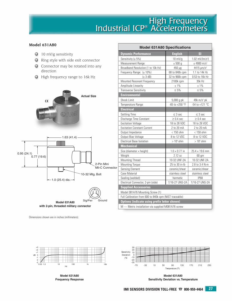
IMI SENSORS DIVISION TOLL-FREE � 800-959-4464 27
High FrequencyIndustrial ICP® Accelerometers
High FrequencyIndustrial ICP® Accelerometers
Model 631A80
10 mV/g sensitivity
Ring style with side exit connector
Connector may be rotated into any direction
High frequency range to 16k Hz
Actual Size
Model 631A80 Specifications
Dynamic Performance English SISensitivity (± 5%) 10 mV/g 1.02 mV/(m/s2)Measurement Range ± 500 g ± 4900 m/s2
Broadband Resolution (1 to 10k Hz) 450 µg 4415 µm/s2
Frequency Range: (± 10%) 68 to 840k cpm 1.1 to 14k Hz(± 3 dB) 32 to 960k cpm 0.53 to 16k Hz
Mounted Resonant Frequency 2100k cpm 35k HzAmplitude Linearity ± 1% ± 1%Transverse Sensitivity ≤ 5% ≤ 5%
EnvironmentalShock Limit 5,000 g pk 49k m/s2 pkTemperature Range -65 to +250 °F -54 to +121 °C
ElectricalSettling Time ≤ 3 sec ≤ 3 secDischarge Time Constant ≥ 0.4 sec ≥ 0.4 secExcitation Voltage 18 to 28 VDC 18 to 28 VDCExcitation Constant Current 2 to 20 mA 2 to 20 mAOutput Impedance < 150 ohm < 150 ohmOutput Bias Voltage 8 to 12 VDC 8 to 12 VDCElectrical Base Isolation > 108 ohm > 108 ohm
MechanicalSize (diameter × height) 1.0 × 0.77 in 25.4 × 19.6 mmWeight 2.12 oz 60 gmMounting Thread 10-32 UNF-2A 10-32 UNF-2AMounting Torque 25 to 30 in-lb 2.8 to 3.4 N-mSensing Element ceramic/shear ceramic/shearCase Material stainless steel stainless steelSealing (welded) hermetic IP68Electrical Connector, 2-pin (side) 7/16-27 UNS-2A 7/16-27 UNS-2A
Supplied AccessoriesModel 081A76 Mounting Screw (1)Full Calibration from 600 to 840k cpm (NIST traceable)
Options (indicate using prefix letter shown)M — Metric installation via supplied M081A76 screw
Model 631A80with 2-pin, threaded military connector
Dimensions shown are in inches (millimeters).
Model 631A80 Frequency Response
Model 631A80 Sensitivity Deviation vs. Temperature

24-HOUR SENSORLINESM 716-684-0003 • WEB SITE — www.imi-sensors.com28
High FrequencyIndustrial ICP® AccelerometersHigh FrequencyIndustrial ICP® Accelerometers
Model 635A01
100 mV/g sensitivity
Ring style with side exit connector
Connector may be rotated into any direction
High frequency range to 15k Hz
Actual Size
Model 635A01 Specifications
Dynamic Performance English SISensitivity (± 5%) 100 mV/g 10.2 mV/(m/s2)Measurement Range ± 50 g ± 490 m/s2
Broadband Resolution (1 to 10k Hz) 240 µg 2354 µm/s2
Frequency Range: (± 10%) 68 to 720k cpm 1.1 to 12k Hz(± 3 dB) 32 to 900k cpm 0.53 to 15k Hz
Mounted Resonant Frequency 1800k cpm 30k HzAmplitude Linearity ± 1% ± 1%Transverse Sensitivity ≤ 5% ≤ 5%
EnvironmentalShock Limit 5,000 g pk 49k m/s2 pkTemperature Range -65 to +250 °F -54 to +121 °C
ElectricalSettling Time ≤ 2 sec ≤ 2 secDischarge Time Constant ≥ 0.3 sec ≥ 0.3 secExcitation Voltage 18 to 28 VDC 18 to 28 VDCExcitation Constant Current 2 to 20 mA 2 to 20 mAOutput Impedance < 150 ohm < 150 ohmOutput Bias Voltage 8 to 12 VDC 8 to 12 VDCElectrical Base Isolation > 108 ohm > 108 ohm
MechanicalSize (dia × height) 1.12 × 0.85 in 28.5 × 21.6 mmWeight 3.0 oz 86 gmMounting Thread 1/4-28 UNF-2A 1/4-28 UNF-2AMounting Torque 2 to 5 ft-lb 2.7 to 6.8 N-mSensing Element ceramic/shear ceramic/shearCase Material stainless steel stainless steelSealing (welded) hermetic IP68Electrical Connector, 2-pin (side) MIL-C-5015 MIL-C-5015
Supplied AccessoriesModel 081A97 Mounting Screw (1)Full Calibration from 600 to 720k cpm (NIST traceable)
Options (indicate using prefix letter shown)M — Metric installation via supplied M081A97 screw, M6 × 1.0 thread
Model 635A01with 2-pin, threaded military connector
Dimensions shown are in inches (millimeters).
Model 635A01 Sensitivity Deviation vs. Temperature
Model 635A01 Frequency Response

29
PCB 716-684-0001 IMI Sensors Division toll-free 800-959-4464 Fax 716-684-3823 E-mail [email protected] Web site www.imi-sensors.com
Low FrequencyIndustrial ICP® Accelerometers
Low FrequencyIndustrial ICP® Accelerometers
Vibration measurements on slowrotating machinery
Paper machine rolls
Large structures and machinefoundations
Large fans and air handling equipment
Cooling towers
Buildings, bridges, foundations,and floors
Low-amplitude, vibration levels go hand-in-hand with low- frequency vibration measurements. For this reason, IMIoffers accelerometers combining extended low frequencyresponse with high output sensitivity in order to obtain thedesired resolution characteristics and strong output signallevels, necessary for conducting low-frequency, vibrationmeasurements and analysis.
The most sensitive of IMI’s low frequency accelerometers areknown as seismic accelerometers. These models are larger insize to accommodate their larger seismic, internal masseswhich are necessary to generate a stronger output signal.These sensors have a limited amplitude range which rendersthem unsuitable for many general purpose industrial vibration measurement applications. However, when measur-ing the vibration of slow, rotating machinery, buildings,bridges and large structures, low frequency, low noiseaccelerometers will provide the characteristics required forsuccessful results.
All of these low-frequency industrial accelerometers benefitfrom the same advantages offered by IMI’s general purposeindustrial accelerometers including: rugged, laser-welded,stainless steel housing with the ability to endure dirty, wet, orharsh environments; hermetically sealed military connectoror sealed integral cable; and a low noise, low impedance,voltage output signal with long-distance, signal transmissioncapability.
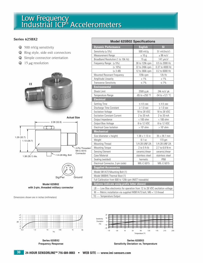
24-HOUR SENSORLINESM 716-684-0003 • WEB SITE — www.imi-sensors.com30
Low FrequencyIndustrial ICP® AccelerometersLow FrequencyIndustrial ICP® Accelerometers
Series 625BX2
500 mV/g sensitivity
Ring style, side exit connectors
Simple connector orientation
15 µg resolution
Model 625B02with 2-pin, threaded military connector
Dimensions shown are in inches (millimeters)
Actual Size
Model 625B02 Specifications
Dynamic Performance English SISensitivity (± 5%) 500 mV/g 51 mV/(m/s2)Measurement Range ± 10 g ± 98 m/s2
Broadband Resolution (1 to 10k Hz) 15 µg 147 µm/s2
Frequency Range: (± 5%) 30 to 120k cpm 0.5 to 2000 Hz(± 10%) 22 to 240k cpm 0.37 to 4000 Hz(± 3 dB) 12 to 360k cpm 0.2 to 6000 Hz
Mounted Resonant Frequency 720k cpm 12k HzAmplitude Linearity ± 1% ± 1%Transverse Sensitivity ≤ 7% ≤ 7%
EnvironmentalShock Limit 2500 g pk 24k m/s2 pkTemperature Range -65 to +250 °F -54 to +121 °C
ElectricalSettling Time ≤ 4.5 sec ≤ 4.5 secDischarge Time Constant ≥ 1.0 sec ≥ 1.0 secExcitation Voltage 18 to 28 VDC 18 to 28 VDCExcitation Constant Current 2 to 20 mA 2 to 20 mAOutput Impedance < 100 ohm < 100 ohmOutput Bias Voltage 8 to 12 VDC 8 to 12 VDCElectrical Case Isolation > 108 ohm > 108 ohm
MechanicalSize (diameter × height) 1.38 × 1.13 in 35 × 28.7 mmWeight 6.1 oz 173 gmMounting Thread 1/4-28 UNF-2A 1/4-28 UNF-2AMounting Torque 2 to 5 ft-lb 2.7 to 6.8 N-mSensing Element ceramic/shear ceramic/shearCase Material stainless steel stainless steelSealing (welded) hermetic IP68Electrical Connector, 2-pin (side) MIL-C-5015 MIL-C-5015
Supplied AccessoriesModel 081A73 Mounting Bolt (1)Model 080B45 Thermal Boot (1)Full Calibration from 600 to 120k cpm (NIST traceable)
Options (indicate using prefix letter shown)LB — Low Bias electronics for operation from 12 to 28 VDC excitation voltageM — Metric installation via supplied M081A73 bolt, M6 × 1.0 threadTO — Temperature Output
Series 625BX2 Sensitivity Deviation vs. Temperature
Series 625BX2 Frequency Response

IMI SENSORS DIVISION TOLL-FREE � 800-959-4464 31
Low FrequencyIndustrial ICP® Accelerometers
Low FrequencyIndustrial ICP® Accelerometers
Series 625BX2 — additional base model configurations
Available models in this series Accelerometers Accelerometers with additionaltemperature output signal of 10 mV/°C
Two-pin, threaded military connector 625B02 TO625B02*Integral, 10 ft (3 m) polyurethane cable 625B12 TO625B12Integral, 10 ft (3 m) Teflon cable 625B22 —Three-pin, bayonet military connector 625B32 —Integral, 10 ft (3 m) steel-armored, polyurethane cable 625B62 TO625B62
Options (indicate using prefix letter shown)LB — Low Bias electronics for operation from 12 to 28 VDC excitation voltageM — Metric installation via supplied M081A73 bolt, M6 × 1.0 thread
NOTES: * Model TO625B02 features a 3-pin, threaded military connector to accommodate the additional temperature output signal.
Model 625B32 with 3-pin, bayonet military connector
Model 625B12 with integral, 10 ft (3 m) polyurethane cable
Model 625B22 with integral, 10 ft (3 m) Teflon cable
Model 625B62with integral, 10 ft (3 m) steel-armored, polyurethane cable

24-HOUR SENSORLINESM 716-684-0003 • WEB SITE — www.imi-sensors.com32
Low FrequencyIndustrial ICP® AccelerometersLow FrequencyIndustrial ICP® Accelerometers
Series 626AX1
100 mV/g sensitivity
Top exit connectors
100 micro g resolution
Model 626A01with 2-pin, threaded military connector
Dimensions shown are in inches (millimeters).
Actual Size
Model 626A01 Specifications
Dynamic Performance English SISensitivity (± 5%) 100 mV/g 10.2 mV/(m/s2)Measurement Range ± 50 g ± 490 m/s2
Broadband Resolution (1 to 10k Hz) 100 µg 981 µm/s2
Frequency Range: (± 5%) 30 to 300k cpm 0.5 to 5000 Hz(± 10%) 18 to 420k cpm 0.3 to 7000 Hz(± 3 dB) 12 to 600k cpm 0.2 to 10k Hz
Mounted Resonant Frequency 1200k cpm 20k HzAmplitude Linearity ± 1% ± 1%Transverse Sensitivity ≤ 5% ≤ 5%
EnvironmentalShock Limit 5000 g pk 49k m/s2 pkTemperature Range -65 to +250 °F -54 to +121 °C
ElectricalSettling Time ≤ 5 sec ≤ 5 secDischarge Time Constant ≥ 1.0 sec ≥ 1.0 secExcitation Voltage 18 to 28 VDC 18 to 28 VDCExcitation Constant Current 2 to 20 mA 2 to 20 mAOutput Impedance < 100 ohm < 100 ohmOutput Bias Voltage 8 to 12 VDC 8 to 12 VDCElectrical Case Isolation > 108 ohm > 108 ohmElectrical Protection RFI/ESD RFI/ESD
MechanicalSize (hex × height) 1 3/16 × 2.30 in 1 3/16 in × 58.4 mmWeight 5.3 oz 150 gmMounting Thread 1/4-28 UNF-2B 1/4-28 UNF-2BMounting Torque 2 to 5 ft-lb 2.7 to 6.8 N-mSensing Element ceramic/shear ceramic/shearCase Material stainless steel stainless steelSealing (welded) hermetic IP68Electrical Connector, 2-pin (top) MIL-C-5015 MIL-C-5015
Supplied AccessoriesModel 081A40 Mounting Stud (1)Model 085A31 Thermal Boot (1)Full Calibration from 600 to 300k cpm (NIST traceable)
Options (indicate using prefix letter shown)LB — Low Bias electronics for operation from 12 to 28 VDC excitation voltageM — Metric installation via supplied M081A61 stud, 1/4-28 to M6 × 1.0
TO — Temperature Output
Series 626AX1 Sensitivity Deviation vs. Temperature
Series 626AX1 Frequency Response

IMI SENSORS DIVISION TOLL-FREE � 800-959-4464 33
Low FrequencyIndustrial ICP® Accelerometers
Low FrequencyIndustrial ICP® Accelerometers
Available models in this series Accelerometers Accelerometers with Velocityadditional temperature Sensorsoutput signal of 10 mV/°C
Two-pin, threaded military connector 626A01 TO626A01* VO626A01†
Integral, 10 ft (3 m) polyurethane cable 626A11 TO626A11 —Integral, 10 ft (3 m) Teflon cable 626A21 — VO626A21†
Three-pin, bayonet military connector 626A31 — —Integral, 10 ft (3 m) steel-armored, polyurethane cable 626A61 TO626A61 —Options (indicate using prefix letter shown)LB — Low Bias electronics for operation from 12 to 28 VDC excitation voltage
M — Metric installation via supplied M081A61 stud, 1/4-28 to M6 × 1.0
NOTES: * Model TO626A01 features a 3-pin, threaded military connector to accommodate the additional temperature output signal.† See pages 17 and 18 for Velocity Sensor specifications and drawings.
Additional Versions (see page 36): 500 mV/g - Series 626AX2; 1000 mV/g - Series 626AX3
Model 626A31 with 3-pin, bayonet military connector
Model 626A11 with integral, 10 ft (3 m) polyurethane cable
Model 626A21 with integral, 10 ft (3 m) Teflon cable
Model 626A61with integral, 10 ft (3 m) steel-armored, polyurethane cable
Series 626AX1 — additional base model configurations
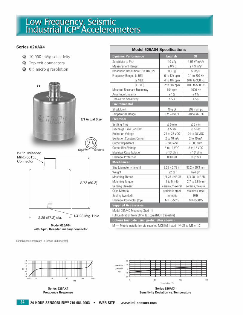
24-HOUR SENSORLINESM 716-684-0003 • WEB SITE — www.imi-sensors.com34
Low Frequency, SeismicIndustrial ICP® AccelerometersLow Frequency, SeismicIndustrial ICP® Accelerometers
Series 626AX4
10,000 mV/g sensitivity
Top exit connectors
0.5 micro g resolution
Model 626A04with 2-pin, threaded military connector
Dimensions shown are in inches (millimeters).
2/3 Actual Size
Model 626A04 Specifications
Dynamic Performance English SISensitivity (± 5%) 10 V/g 1.02 V/(m/s2)Measurement Range ± 0.5 g ± 4.9 m/s2
Broadband Resolution (1 to 10k Hz) 0.5 µg 5 µm/s2
Frequency Range: (± 5%) 6 to 12k cpm 0.1 to 200 Hz(± 10%) 4 to 18k cpm 0.07 to 300 Hz(± 3 dB) 2 to 30k cpm 0.03 to 500 Hz
Mounted Resonant Frequency 60k cpm 1000 HzAmplitude Linearity ± 1% ± 1%Transverse Sensitivity ≤ 5% ≤ 5%
EnvironmentalShock Limit 40 g pk 392 m/s2 pkTemperature Range 0 to +150 °F -18 to +65 °C
ElectricalSettling Time ≤ 5 min ≤ 5 minDischarge Time Constant ≥ 5 sec ≥ 5 secExcitation Voltage 24 to 28 VDC 24 to 28 VDCExcitation Constant Current 2 to 10 mA 2 to 10 mAOutput Impedance < 500 ohm < 500 ohmOutput Bias Voltage 8 to 12 VDC 8 to 12 VDCElectrical Case Isolation > 108 ohm > 108 ohmElectrical Protection RFI/ESD RFI/ESD
MechanicalSize (diameter × height) 2.25 × 2.73 in 57.2 × 69.3 mmWeight 22 oz 624 gmMounting Thread 1/4-28 UNF-2B 1/4-28 UNF-2BMounting Torque 2 to 5 ft-lb 2.7 to 6.8 N-mSensing Element ceramic/flexural ceramic/flexuralCase Material stainless steel stainless steelSealing (welded) hermetic IP68Electrical Connector (top) MIL-C-5015 MIL-C-5015
Supplied AccessoriesModel 081A40 Mounting Stud (1)Full Calibration from 30 to 12k cpm (NIST traceable)
Options (indicate using prefix letter shown)M — Metric installation via supplied M081A61 stud, 1/4-28 to M6 × 1.0
Series 626AX4 Sensitivity Deviation vs. Temperature
Series 626AX4 Frequency Response

IMI SENSORS DIVISION TOLL-FREE � 800-959-4464 35
Low Frequency, SeismicIndustrial ICP® Accelerometers
Low Frequency, SeismicIndustrial ICP® Accelerometers
Available models in this series AccelerometersTwo-pin, threaded military connector 626A04
Integral, 10 ft (3 m) polyurethane cable 626A14
Integral, 10 ft (3 m) Teflon cable 626A24
Three-pin, bayonet military connector 626A34
Integral, 10 ft (3 m) steel-armored, polyurethane cable 626A64
Options (indicate using prefix letter shown)M — Metric installation via supplied M081A61 stud, 1/4-28 to M6 × 1.0
Model 626A34 with 3-pin, bayonet military connector
Model 626A14 with integral, 10 ft (3 m) polyurethane cable
Model 626A24 with integral, 10 ft (3 m) Teflon cable
Model 626A64with integral, 10 ft (3 m) steel-armored, polyurethane cable
Series 626AX4 — additional base model configurations

24-HOUR SENSORLINESM 716-684-0003 • WEB SITE — www.imi-sensors.com
Low FrequencyIndustrial ICP® AccelerometersLow FrequencyIndustrial ICP® Accelerometers
36
Series 626AX2 Series 626AX3
Dynamic Performance English SI English SISensitivity (± 5%) 500 mV/g 51 mV/(m/s2) 1000 mV/g 102 mV/(m/s2)Measurement Range ± 10 g ± 98 m/s2 ± 5 g ± 49 m/s2
Broadband Resolution (1 to 10k Hz) 15 µg 147 µm/s2 10 µg 98 µm/s2
Frequency Range: (± 5%) 30 to 120k cpm 0.5 to 2000 Hz 30 to 120k cpm 0.5 to 2000 Hz(± 10%) 18 to 240k cpm 0.3 to 4000 Hz 18 to 240k cpm 0.3 to 4000 Hz(± 3 dB) 12 to 360k cpm 0.2 to 6000 Hz 12 to 360k cpm 0.2 to 6000 Hz
Mounted Resonant Frequency 720k cpm 12k Hz 720k cpm 12k HzAmplitude Linearity ± 1% ± 1% ± 1% ± 1%Transverse Sensitivity ≤ 7% ≤ 7% ≤ 7% ≤ 7%
EnvironmentalShock Limit 2500 g pk 24k m/s2 pk 2500 g pk 24.5k m/s2 pkTemperature Range -65 to +250 °F -54 to +121 °C -65 to +250 °F -54 to +121 °C
ElectricalSettling Time ≤ 5 sec ≤ 5 sec ≤ 10 sec ≤ 10 secDischarge Time Constant ≥ 1.0 sec ≥ 1.0 sec ≥ 1.0 sec ≥ 1.0 secExcitation Voltage 18 to 28 VDC 18 to 28 VDC 18 to 28 VDC 18 to 28 VDCExcitation Constant Current 2 to 20 mA 2 to 20 mA 2 to 20 mA 2 to 20 mAOutput Impedance < 100 ohm < 100 ohm < 100 ohm < 100 ohmOutput Bias Voltage 8 to 12 VDC 8 to 12 VDC 8 to 12 VDC 8 to 12 VDCElectrical Case Isolation > 108 ohm > 108 ohm > 108 ohm > 108 ohmElectrical Protection RFI/ESD RFI/ESD RFI/ESD RFI/ESD
MechanicalSize (hex × height) 1 3/16 × 2.19 in 1 3/16 in × 55.6 mm 1 3/16 × 2.19 in 1 3/16 in × 55.6 mmWeight 7.4 oz 210 gm 7.4 oz 210 gmMounting Thread 1/4-28 UNF-2B 1/4-28 UNF-2B 1/4-28 UNF-2B 1/4-28 UNF-2BMounting Torque 2 to 5 ft-lb 2.7 to 6.8 N-m 2 to 5 ft-lb 2.7 to 6.8 N-mSensing Element ceramic/shear ceramic/shear ceramic/shear ceramic/shearCase Material stainless steel stainless steel stainless steel stainless steelSealing (welded) hermetic IP68 hermetic IP68Electrical Connector, 2-pin (top) MIL-C-5015 MIL-C-5015 MIL-C-5015 MIL-C-5015
Supplied AccessoriesMounting Stud or Bolt Model 081A40 (1) Model 081A40 (1)Thermal Boot Model 085A31 (1) Model 085A31 (1)Calibration (NIST traceable) From 600 to 120K cpm From 600 to 120k cpm
Available VersionsTwo-pin, Threaded Military Connector 626A02 626A03Integral, 10 ft (3 m) Polyurethane Cable 626A12 626A13Integral, 10 ft (3 m) Teflon Cable 626A22 626A23Three-pin, Bayonet Military Connector 626A32 626A33Integral, 10 ft (3 m) Steel-armored Cable 626A62 626A63
Options (Indicate using prefix letter shown)Low Bias Electronics LB LBMetric Installation M* M*Temperature Output TO† TO§
NOTES: * Metric installation via supplied M081A61 stud, ¼-28 to M6 × 1.0† TO626A02, TO626A12, TO626A62 versions only. Model TO626A02 features a 3-pin, threaded
military connector to accommodate the additional temperature output signal.§ TO626A03, TO626A13, TO626A63 versions only. Model TO626A03 features a 3-pin, threaded
military connector to accommodate the additional temperature output signal.
Additional LowFrequencyIndustrial ICP®
Accelerometers
500 mV/g15 µg resolution
1000 mV/g10 µg resolution
Dimensional drawingsfor Series 626AX2 and626AX3 are identical to those for Series626AX1 shown onpages 32-33.

37
PCB 716-684-0001 IMI Sensors Division toll-free 800-959-4464 Fax 716-684-3823 E-mail [email protected] Web site www.imi-sensors.com
Multi-Axis IndustrialICP® AccelerometersMulti-Axis IndustrialICP® Accelerometers
Measure acceleration simultaneouslyin up to three axes
Through-bolt mounting for simplified alignment
Simultaneous radial and axialbearing vibration measurements
Interface directly with vibrationdata collectors and FFT analyzers
Multi-axis accelerometers contain two or three independentacceleration sensing elements within the same housing. Thesensing elements are oriented in mutually perpendiculargeometries in order to respond to vibration in independent,orthogonal directions. Biaxial accelerometers contain twosensing elements whereas triaxial versions contain three.Each sensing axis contains a dedicated, built-in, low-noise,microelectronic signal amplifier whose output signal is delivered to an independent cable lead or connector pin.
Multi-axis measurements are useful for radial vs. axial bearing vibration monitoring, machinery foundation troubleshooting, and structural impulse and response studies. Styles for low cost and precision requirements aredifferentiated by their sensitivity tolerances and extent ofsupplied NIST traceable calibration.
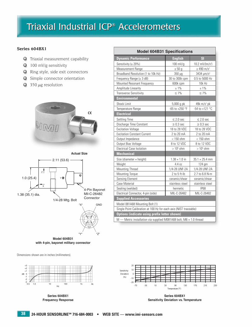
24-HOUR SENSORLINESM 716-684-0003 • WEB SITE — www.imi-sensors.com38
Triaxial Industrial ICP® AccelerometersTriaxial Industrial ICP® Accelerometers
Series 604BX1
Triaxial measurement capability
100 mV/g sensitivity
Ring style, side exit connectors
Simple connector orientation
350 µg resolution
Model 604B31with 4-pin, bayonet military connector
Dimensions shown are in inches (millimeters).
Actual Size
Model 604B31 Specifications
Dynamic Performance English SISensitivity (± 20%) 100 mV/g 10.2 mV/(m/s2)Measurement Range ± 50 g ± 490 m/s2
Broadband Resolution (1 to 10k Hz) 350 µg 3434 µm/s2
Frequency Range (± 3 dB) 30 to 300k cpm 0.5 to 5000 HzMounted Resonant Frequency 600k cpm 10k HzAmplitude Linearity ± 1% ± 1%Transverse Sensitivity ≤ 7% ≤ 7%
EnvironmentalShock Limit 5,000 g pk 49k m/s2 pkTemperature Range -65 to +250 °F -54 to +121 °C
ElectricalSettling Time ≤ 2.0 sec ≤ 2.0 secDischarge Time Constant ≥ 0.3 sec ≥ 0.3 secExcitation Voltage 18 to 28 VDC 18 to 28 VDCExcitation Constant Current 2 to 20 mA 2 to 20 mAOutput Impedance < 150 ohm < 150 ohmOutput Bias Voltage 8 to 12 VDC 8 to 12 VDCElectrical Case Isolation > 108 ohm > 108 ohm
MechanicalSize (diameter × height) 1.38 × 1.0 in 35.1 × 25.4 mmWeight 4.4 oz 124 gmMounting Thread 1/4-28 UNF-2A 1/4-28 UNF-2AMounting Torque 2 to 5 ft-lb 2.7 to 6.8 N-mSensing Element ceramic/shear ceramic/shearCase Material stainless steel stainless steelSealing (welded) hermetic IP68Electrical Connector, 4-pin (side) MIL-C-26482 MIL-C-26482
Supplied AccessoriesModel 081A68 Mounting Bolt (1)Single Point Calibration at 100 Hz for each axis (NIST traceable)
Options (indicate using prefix letter shown)M — Metric installation via supplied M081A68 bolt, M6 × 1.0 thread
Series 604BX1 Sensitivity Deviation vs. Temperature
Series 604BX1 Frequency Response

IMI SENSORS DIVISION TOLL-FREE � 800-959-4464 39
Triaxial Industrial ICP® AccelerometersTriaxial Industrial ICP® Accelerometers
Series 604BX1 — additional base model configurations
Available models in this series Triaxial AccelerometersIntegral, 10 ft (3 m) polyurethane cable 604B11
Four-pin, bayonet military connector 604B31
Integral, 10 ft (3 m) steel-armored, polyurethane cable 604B61
Options (indicate using prefix letter shown)M — Metric installation via supplied M081A68 bolt, M6 × 1.0 thread
Model 604B11 with integral, 10 ft (3 m) polyurethane cable
Model 604B61with integral, 10 ft (3 m) steel-armored, polyurethane cable
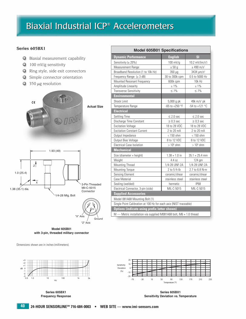
24-HOUR SENSORLINESM 716-684-0003 • WEB SITE — www.imi-sensors.com40
Biaxial Industrial ICP® AccelerometersBiaxial Industrial ICP® Accelerometers
Series 605BX1
Biaxial measurement capability
100 mV/g sensitivity
Ring style, side exit connectors
Simple connector orientation
350 µg resolution
Model 605B01with 3-pin, threaded military connector
Dimensions shown are in inches (millimeters).
Actual Size
Model 605B01 Specifications
Dynamic Performance English SISensitivity (± 20%) 100 mV/g 10.2 mV/(m/s2)Measurement Range ± 50 g ± 490 m/s2
Broadband Resolution (1 to 10k Hz) 350 µg 3434 µm/s2
Frequency Range (± 3 dB) 30 to 300k cpm 0.5 to 5000 HzMounted Resonant Frequency 600k cpm 10k HzAmplitude Linearity ± 1% ± 1% Transverse Sensitivity ≤ 7% ≤ 7%
EnvironmentalShock Limit 5,000 g pk 49k m/s2 pkTemperature Range -65 to +250 °F -54 to +121 °C
ElectricalSettling Time ≤ 2.0 sec ≤ 2.0 secDischarge Time Constant ≥ 0.3 sec ≥ 0.3 secExcitation Voltage 18 to 28 VDC 18 to 28 VDCExcitation Constant Current 2 to 20 mA 2 to 20 mAOutput Impedance < 150 ohm < 150 ohmOutput Bias Voltage 8 to 12 VDC 8 to 12 VDCElectrical Case Isolation > 108 ohm > 108 ohm
MechanicalSize (diameter × height) 1.38 × 1.0 in 35.1 × 25.4 mmWeight 4.4 oz 124 gmMounting Thread 1/4-28 UNF-2A 1/4-28 UNF-2AMounting Torque 2 to 5 ft-lb 2.7 to 6.8 N-mSensing Element ceramic/shear ceramic/shearCase Material stainless steel stainless steelSealing (welded) hermetic IP68Electrical Connector, 3-pin (side) MIL-C-5015 MIL-C-5015
Supplied AccessoriesModel 081A68 Mounting Bolt (1)Single Point Calibration at 100 Hz for each axis (NIST traceable)
Options (indicate using prefix letter shown)M — Metric installation via supplied M081A68 bolt, M6 × 1.0 thread
Series 605BX1 Sensitivity Deviation vs. Temperature
Series 605BX1 Frequency Response

IMI SENSORS DIVISION TOLL-FREE � 800-959-4464 41
Biaxial Industrial ICP® AccelerometersBiaxial Industrial ICP® Accelerometers
Series 605BX1 — additional base model configurations
Available models in this series Biaxial AccelerometersThree-pin, threaded military connector 605B01
Integral, 10 ft (3 m) polyurethane cable 605B11
Three-pin, bayonet military connector 605B31
Integral, 10 ft (3 m) steel-armored, polyurethane cable 605B61
Options (indicate using prefix letter shown)M — Metric installation via supplied M081A68 bolt, M6 × 1.0 thread
Model 605B11 with integral, 10 ft (3 m) polyurethane cable
Model 605B61with integral, 10 ft (3 m) steel-armored, polyurethane cable
Model 605B31 with 3-pin bayonet, military connector

24-HOUR SENSORLINESM 716-684-0003 • WEB SITE — www.imi-sensors.com42
Triaxial Industrial ICP® AccelerometersTriaxial Industrial ICP® Accelerometers
Series 629AX1
Triaxial measurement capability
100 mV/g sensitivity
Block style, side exit connectors
Through-hole mounting
Simple connector orientation
100 µg resolution
Model 629A31with 4-pin, bayonet military connector
Dimensions shown are in inches (millimeters).
Actual Size
Model 629A31 Specifications
Dynamic Performance English SISensitivity (± 5%) 100 mV/g 10.2 mV/(m/s2)Measurement Range ± 50 g ± 490 m/s2
Broadband Resolution (1 to 10k Hz) 100 µg 981 µm/s2
Frequency Range: (± 5%) 144 to 120k cpm 2.4 to 2000 Hz(± 10%) 102 to 300k cpm 1.7 to 5000 Hz(± 3 dB) 48 to 480k cpm 0.8 to 8000 Hz
Mounted Resonant Frequency 1200k cpm 20k HzAmplitude Linearity ± 1% ± 1%Transverse Sensitivity ≤ 5% ≤ 5%
EnvironmentalShock Limit 5,000 g pk 49k m/s2 pkTemperature Range -65 to +250 °F -54 to +121 °C
ElectricalSettling Time ≤ 3.0 sec ≤ 3.0 secDischarge Time Constant ≥ 0.2 sec ≥ 0.2 secExcitation Voltage 18 to 28 VDC 18 to 28 VDCExcitation Constant Current 2 to 20 mA 2 to 20 mAOutput Impedance < 100 ohm < 100 ohmOutput Bias Voltage 8 to 12 VDC 8 to 12 VDCElectrical Case Isolation > 108 ohm > 108 ohmElectrical Protection RFI/ESD RFI/ESD
MechanicalSize (length × width × height) 1.5 × 1.5 × 0.835 in 38.1 × 38.1 × 21.2 mmWeight 4.9 oz 139 gmMounting Thread 1/4-28 UNF-2A 1/4-28 UNF-2AMounting Torque 2 to 5 ft-lb 2.7 to 6.8 N-mSensing Element ceramic/shear ceramic/shearCase Material stainless steel stainless steelSealing (welded) hermetic IP68Electrical Connector, 4-pin (side) MIL-C-26482 MIL-C-26482
Supplied AccessoriesModel 081A56 Mounting Bolt (1)Full Calibration from 600 to 120k cpm for each axis (NIST traceable)
Options (indicate using prefix letter shown)LB — Low bias electronics for operation from 12 to 28 VDC excitation voltageM — Metric installation via supplied M081A59 bolt, M6 × 1.0 thread
Series 629AX1 Sensitivity Deviation vs. Temperature
Series 629AX1 Frequency Response

IMI SENSORS DIVISION TOLL-FREE � 800-959-4464 43
Triaxial Industrial ICP® AccelerometersTriaxial Industrial ICP® Accelerometers
Series 629AX1 — additional base model configurations
Available models in this series Triaxial AccelerometersIntegral, 10 ft (3 m) polyurethane cable 629A11
Four-pin, bayonet military connector 629A31
Integral, 10 ft (3 m) steel-armored, polyurethane cable 629A61
Options (indicate using prefix letter shown)LB — Low bias electronics for operation from 12 to 28 VDC excitation voltage
M — Metric installation via supplied M081A59 bolt, M6 × 1.0 thread
Model 629A11 with integral, 10 ft (3 m) polyurethane cable
Model 629A61with integral, 10 ft (3 m) steel-armored, polyurethane cable
Actual Size
Actual Size
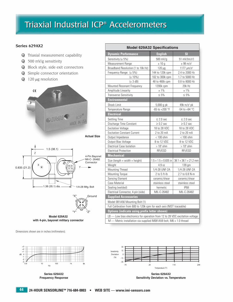
24-HOUR SENSORLINESM 716-684-0003 • WEB SITE — www.imi-sensors.com44
Triaxial Industrial ICP® AccelerometersTriaxial Industrial ICP® Accelerometers
Series 629AX2
Triaxial measurement capability
500 mV/g sensitivity
Block style, side exit connectors
Simple connector orientation
120 µg resolution
Model 629A32with 4-pin, bayonet military connector
Dimensions shown are in inches (millimeters).
0.835 (21.2)
Actual Size
Model 629A32 Specifications
Dynamic Performance English SISensitivity (± 5%) 500 mV/g 51 mV/(m/s2)Measurement Range ± 10 g ± 98 m/s2
Broadband Resolution (1 to 10k Hz) 120 µg 1177 µm/s2
Frequency Range: (± 5%) 144 to 120k cpm 2.4 to 2000 Hz(± 10%) 102 to 300k cpm 1.7 to 5000 Hz(± 3 dB) 48 to 480k cpm 0.8 to 8000 Hz
Mounted Resonant Frequency 1200k cpm 20k HzAmplitude Linearity ± 1% ± 1%Transverse Sensitivity ≤ 5% ≤ 5%
EnvironmentalShock Limit 5,000 g pk 49k m/s2 pkTemperature Range -65 to +200 °F -54 to +94 °C
ElectricalSettling Time ≤ 2.0 sec ≤ 2.0 secDischarge Time Constant ≥ 0.2 sec ≥ 0.2 secExcitation Voltage 18 to 28 VDC 18 to 28 VDCExcitation Constant Current 2 to 20 mA 2 to 20 mAOutput Impedance < 100 ohm < 100 ohmOutput Bias Voltage 8 to 12 VDC 8 to 12 VDCElectrical Case Isolation > 108 ohm > 108 ohmElectrical Protection RFI/ESD RFI/ESD
MechanicalSize (length × width × height) 1.5 × 1.5 × 0.835 in 38.1 × 38.1 × 21.2 mmWeight 4.9 oz 139 gmMounting Thread 1/4-28 UNF-2A 1/4-28 UNF-2AMounting Torque 2 to 5 ft-lb 2.7 to 6.8 N-mSensing Element ceramic/shear ceramic/shearCase Material stainless steel stainless steelSealing (welded) hermetic IP68Electrical Connector, 4-pin (side) MIL-C-26482 MIL-C-26482
Supplied AccessoriesModel 081A56 Mounting Bolt (1)Full Calibration from 600 to 120k cpm for each axis (NIST traceable)
Options (indicate using prefix letter shown)LB — Low bias electronics for operation from 12 to 28 VDC excitation voltageM — Metric installation via supplied M081A59 bolt, M6 × 1.0 thread
Series 629AX2 Sensitivity Deviation vs. Temperature
Series 629AX2 Frequency Response

IMI SENSORS DIVISION TOLL-FREE � 800-959-4464 45
Triaxial Industrial ICP® AccelerometersTriaxial Industrial ICP® Accelerometers
Series 629AX2 — additional base model configurations
Available models in this series Triaxial AccelerometersIntegral, 10 ft (3 m) polyurethane cable 629A12
Four-pin, bayonet military connector 629A32
Integral, 10 ft (3 m) steel-armored, polyurethane cable 629A62
Options (indicate using prefix letter shown)LB — Low bias electronics for operation from 12 to 28 VDC excitation voltage
M — Metric installation via supplied M081A59 bolt, M6 × 1.0 thread
Model 629A12 with integral, 10 ft (3 m) polyurethane cable
Model 629A62with integral, 10 ft (3 m) steel-armored, polyurethane cable
Actual Size
Actual Size

24-HOUR SENSORLINESM 716-684-0003 • WEB SITE — www.imi-sensors.com
Triaxial Industrial ICP® AccelerometersTriaxial Industrial ICP® Accelerometers
46
Model 629M06 Triaxial ICP® Accelerometer
Triaxial measurement capability
100 mV/g sensitivity
Block style with side exit connector
Simple connector orientation
560 µg resolution
Model 629M05 Triaxial Accelerometer
Triaxial measurement capability
100 mV/g sensitivity
Cylindrical style with top exit cable
Alignment pin insures consistent installation orientation
560 µg resolution
Actual Size
Actual Size

High Temperature Industrial Accelerometers
High Temperature Industrial Accelerometers
47
PCB 716-684-0001 IMI Sensors Division toll-free 800-959-4464 Fax 716-684-3823 E-mail [email protected] Web site www.imi-sensors.com
Paper machine dryer sections
Steel mills
Hot conveyor systems
Reactors and digesters
Petrochemical pumps
Food processing equipment
It is often necessary to monitor the vibration levels of rotatingmachinery operating at elevated temperatures or in high temperature environments. Such circumstances place extremedemands on vibration sensors and require the use ofaccelerometers with special design characteristics that extend their useable temperature range beyond that of otherconventional units. For these demanding situations, IMI offerstwo styles of high-temperature vibration sensors.
A variety of ICP® industrial accelerometers are available withthe High Temperature, “HT” option, which extends their useable temperature range up to 325 °F (163 °C). This optionreplaces their standard, internal signal conditioning circuitrywith circuitry that has been specifically designed and tested toreliably withstand elevated temperature extremes. However,there is a slight trade-off with this approach, it willcompromise the frequency response characteristics of thesensor. These accelerometers, although equipped with the“HT” option, will operate in the same manner, and with thesame cabling, data collection, and signal conditioning equip-
ment, as standard, ICP® industrial accelerometers.
For extreme, high-temperature requirements, charge-mode accelerometers are recommended. Designed to
withstand temperatures up to 500 °F (260 °C),charge-mode accelerometers do not contain inter-nal signal conditioning circuits which impose temperature limits on standard ICP® accelerometers.However, since there are no signal conditioning circuits within charge-mode accelerometers, alternative cabling and signal conditioning
equipment is required. To simplify the installation ofthese sensors, complete kits are offered that include
the necessary low-noise cable and in-line charge converter that adapt the charge-mode accelerometers
to conventional ICP® sensor signal conditioners and datacollection equipment.

Through-hole Mount
24-HOUR SENSORLINESM 716-684-0003 • WEB SITE — www.imi-sensors.com
High Temperature, CeramicIndustrial ICP® AccelerometersHigh Temperature, CeramicIndustrial ICP® Accelerometers
48
Model HT622A01 Model HT623C01 Model HT625B01
Dynamic Performance English SI English SI English SISensitivity (5%) 100 mV/g 10.2 mV/(m/s2) 100 mV/g 10.2 mV/(m/s2) 100 mV/g 10.2 mV/(m/s2)Measurement Range ± 50 g ± 490 m/s2 ± 50 g ± 490 m/s2 ± 50 g ± 490 m/s2
Broadband Resolution (1 to 10k Hz) 150 µg 1472 µm/s2 300 µg 2943 µm/s2 200 µg 1962 µm/s2
Frequency Range: (± 5%) 35 to 240k cpm 0.58 to 4000 Hz 144 to 480k cpm 2.4 to 8 kHz 30 to 240k cpm 0.5 to 4000 Hz(± 10%) 25 to 300k cpm 0.42 to 5000 Hz 102 to 540k cpm 1.7 to 9 kHz 22 to 360k cpm 0.37 to 6000 Hz(± 3 dB) 12 to 480k cpm 0.2 to 8000 Hz 48 to 900k cpm 0.8 to 15 kHz 12 to 600k cpm 0.2 to 10k Hz
Mounted Resonant Frequency 1200k cpm 20k Hz 2400k cpm 40k Hz 1380k cpm 23k HzAmplitude Linearity ± 1% ± 1% ± 1% ± 1% ± 1% ± 1%Transverse Sensitivity ≤ 5% ≤ 5% ≤ 5% ≤ 5% ≤ 5% ≤ 5%
EnvironmentalShock Limit 5000 g pk 49k m/s2 pk 5000 g pk 49k m/s2 pk 2000 g pk 19.6k m/s2 pkTemperature Range -65 to +325 °F -54 to +163 °C -65 to +325 °F -54 to +163 °C -65 to +325 °F -54 to +163 °C
ElectricalSettling Time ≤ 5 sec ≤ 5 sec ≤ 1 sec ≤ 1 sec ≤ 8 sec ≤ 8 secDischarge Time Constant ≥ 0.8 sec ≥ 0.8 sec ≥ 0.2 sec ≥ 0.2 sec ≥ 1.0 sec ≥ 1.0 secExcitation Voltage 18 to 28 VDC 18 to 28 VDC 18 to 28 VDC 18 to 28 VDC 18 to 28 VDC 18 to 28 VDCConstant Current 2 to 10 mA 2 to 10 mA 2 to 10 mA 2 to 10 mA 2 to 10 mA 2 to 10 mAOutput Impedance < 700 ohm < 700 ohm < 700 ohm < 700 ohm < 250 ohm < 250 ohmOutput Bias (at 4 mA) 8 to 14 VDC 8 to 14 VDC 7 to 14 VDC 7 to 14 VDC 11 to 14 VDC 11 to 14 VDCCase Isolation > 108 ohm > 108 ohm > 108 ohm > 108 ohm > 108 ohm > 108 ohmElectrical Protection RFI/ESD RFI/ESD RFI/ESD RFI/ESD — —
MechanicalSize 7/8 hex × 2.0 in 7/8 in hex × 50.8 mm 11/16 hex × 1.97 in 11/16 in hex × 50 mm 1.36 dia. × 1.13 in 35 dia. × 29 mmWeight 3.3 oz 93 gm 1.80 oz 51 gm 5.1 oz 145 gmMounting Thread 1/4-28 UNF-2B 1/4-28 UNF-2B 1/4-28 UNF-2B 1/4-28 UNF-2B 1/4-28 UNF-2A 1/4-28 UNF-2AMounting Torque 2 to 5 ft-lb 2.7 to 6.8 N-m 2 to 5 ft-lb 2.7 to 6.8 N-m 2 to 5 ft-lb 2.7 to 6.8 N-mSensing Element/Geometry ceramic/shear ceramic/shear ceramic/shear ceramic/shear ceramic/shear ceramic/shearCase Material stainless steel stainless steel stainless steel stainless steel stainless steel stainless steelSealing welded hermetic welded hermetic welded hermetic welded hermetic welded hermetic welded hermeticConnector Type (2-pin)/Position MIL-C-5015/Top MIL-C-5015/Top MIL-C-5015/Top MIL-C-5015/Top MIL-C-5015/Side MIL-C-5015/Side
Supplied AccessoriesMounting Stud or Bolt Model 081A40 (1) Model 081A40 (1) Model 081A73 (1)Calibration (NIST traceable) From 600 to 240k cpm From 600 to 480k cpm From 600 to 240k cpm
Options (indicate using prefix letter shown)Metric Installation M* M* M†
NOTES: *Metric installation via supplied M081A61 stud, 1/4-28 to M6 × 1.0
†Metric installation via supplied M081A73 bolt, M6 × 1.0 thread
High Temperature,Industrial ICP®
Accelerometers withCeramic SensingElement
HighFrequency
Low Noise
Models HT622A01, HT623C01, and HT625B01Sensitivity Deviation vs. Temperature

IMI SENSORS DIVISION TOLL-FREE � 800-959-4464
High Temperature, QuartzIndustrial ICP® Accelerometers
High Temperature, QuartzIndustrial ICP® Accelerometers
49
Model HT628F01 Model HT624A01
Dynamic Performance English SI English SISensitivity (± 5%) 100 mV/g 10.2 mV/(m/s2) 100 mV/g 10.2 mV/(m/s2)Measurement Range ± 50 g ± 490 m/s2 ± 50 g ± 490 m/s2
Broadband Resolution (1 to 10k Hz) 1000 µg 9800 µm/s2 1000 µg 9810 µm/s2
Frequency Range: (± 5%) 144 to 180k cpm 2.4 to 3000 Hz 144 to 120k cpm 2.4 to 2000 Hz(± 10%) 102 to 300k cpm 1.7 to 5000 Hz 102 to 180k cpm 1.7 to 3000 Hz(± 3 dB) 48 to 480k cpm 0.8 to 8000 Hz 48 to 300k cpm 0.8 to 5000 Hz
Mounted Resonant Frequency 1080k cpm 18k Hz 1080k cpm 18k HzAmplitude Linearity ± 1% ± 1% ± 1% ± 1 %Transverse Sensitivity ≤ 5% ≤ 5% ≤ 5% ≤ 5%
EnvironmentalShock Limit 1,000 g pk 981 m/s2 pk 1,000 g pk 981 m/s2 pkTemperature Range -65 to +325 °F -54 to +162 °C - 65 to +325 °F - 54 to +162 °C
ElectricalSettling Time ≤ 3 sec ≤ 3 sec ≤ 3 sec ≤ 3 secDischarge Time Constant ≥ 0.5 sec ≥ 0.5 sec ≥ 0.2 sec ≥ 0.2 secExcitation Voltage 18 to 28 VDC 18 to 28 VDC 18 to 28 VDC 18 to 28 VDCExcitation Constant Current 2 to 10 mA 2 to 10 mA 2 to 10 mA 2 to10 mAOutput Impedance < 500 ohm < 500 ohm < 500 ohm < 500 ohmOutput Bias Voltage 8 to 12 VDC 8 to 12 VDC 8 to 12 VDC 8 to 12 VDCElectrical Case Isolation > 108 ohm > 108 ohm > 108 ohm > 108 ohmElectrical Protection RFI/ESD RFI/ESD RFI/ESD RFI/ESD
MechanicalSize 7/8 hex × 2.05 in 7/8 in hex × 52.1 mm 1.375 dia. × 1.125 in 34.9 dia. × 28.6 mmWeight 3.2 oz 91 gm 5.1 oz 145 gmMounting Thread 1/4-28 UNF-2B 1/4-28 UNF-2B 1/4-28 UNF-2A 1/4-28 UNF-2AMounting Torque 2 to 5 ft-lb 2.7 to 6.8 N-m 2 to 5 ft-lb 2.7 to 6.8 N-mSensing Element quartz/shear quartz/shear quartz/shear quartz/shearCase Material stainless steel stainless steel stainless steel stainless steelSealing (Welded) hermetic hermetic hermetic hermeticElectrical Connector, 2-pin/Position MIL-C-5015/Top MIL-C-5015/Top MIL-C-5015/Side MIL-C-5015/Side
Supplied AccessoriesMounting Stud or Bolt Model 081A40 (1) Model 081A57 (1)Calibration (NIST traceable) From 600 to 300k cpm From 600 to 120k cpm
Options (Indicate using prefix letter shown)Metric Installation M* M†
NOTES: *Metric installation via supplied M081A61 stud, 1/4-28 to M6 × 1.0
†Metric installation via supplied M081A58 bolt, M6 × 1.0 thread
High Temperature,Industrial ICP®
Accelerometers withQuartz SensingElement
Quartz Element Quartz Element
Models HT628F01 and HT624A01Sensitivity Deviation vs. temperature

24-HOUR SENSORLINESM 716-684-0003 • WEB SITE — www.imi-sensors.com
High Temperature, Charge-ModeIndustrial Accelerometer KitsHigh Temperature, Charge-ModeIndustrial Accelerometer Kits
50
Model 612A01Industrial Charge-Mode Accelerometer with 2-pin threaded military connector
Model 045M06High-Temperature, Armored Teflon Cable
10 ft (3 m) length
Model 045ER010CJHigh-Temperature Teflon Cable
10 ft (3 m) length
Series 600AXX Industrial Charge-ModeAccelerometer Kits
Sensor operating temperature range up to500 °F (260 °C)
Choice of several sensitivities to suitspecific measurement requirements
Frequency ranges to 10k Hz
The Model 612A01 Charge-Mode Industrial Accelerometeroffers the capability of surviving the highest ambient andsurface temperatures of any of IMI’s industrial vibrationsensors. This is accomplished by utilizing a stainless steel,hermetically sealed, welded housing and eliminating theactive electrical signal conditioning components withinthe unit. (The built-in signal conditioning electronics ofICP® industrial accelerometers impose a limiting factor onthe temperature range for those units).
Charge-mode accelerometers, however, possess uniquesignal conditioning requirements. Their output signal is ata very high impedance which is more susceptible to
extraneous noise influences. To minimize such noise, a short,low-noise cable should be used between the sensor and signal conditioner. The required signal conditioner, also calleda charge converter or charge amplifier, serves to convert thehigh impedance charge signal into a low impedance voltagesignal that can then be transmitted over long cable lengthsand be interrogated by vibration data collectors, readout,recording, and analysis instruments.
For seamless connectivity to vibration data collectors andanalysis instruments, IMI offers charge-mode sensor kitsthat include the Model 612A01 accelerometer, along withan appropriate short length of low-noise cable and acharge converter that provides the desired, system voltagesensitivity. The charge converters will operate from anystandard ICP® sensor signal conditioner, however theymust be located in an environment having a moderate,ambient temperature.
For ease of set-up and implementation, charge sensor kitsare furnished with a system calibration certificate that provides the voltage sensitivity of the sensor/cable/chargeconverter system over the specified frequency range.
Series 422E2XIn-line Charge Converter

IMI SENSORS DIVISION TOLL-FREE � 800-959-4464
High Temperature, Charge-ModeIndustrial Accelerometer Kits
High Temperature, Charge-ModeIndustrial Accelerometer Kits
51
10 mV/g Kits 100 mV/g Kits 1000 mV/g Kits
Available Kit Modelswith 10 ft (3 m) 045ER010CJ Teflon Cable Model 600A06 Model 600A02 Model 600A07with 10 ft (3 m) 045M06 Armored Cable Model 600A08 Model 600A03 Model 600A09
Dynamic Performance (Kit) English SI English SI English SISensitivity (15%) 10 mV/g 1.02 mV/(m/s2) 100 mV/g 10.2 mV/(m/s2) 1000 mV/g 102 mV/(m/s2)Measurement Range 250 g 2452 m/s2 25 g 245 m/s2 2.5 g 24.5 m/s2
Broadband Resolution (1 to 10k Hz) 410 µg 4020 µm/s2 120 µg 1180 µm/s2 120 µg 1180 µm/s2
Frequency Range: (± 10%) 100 to 180k cpm 1.67 to 3000 Hz 100 to 180k cpm 1.67 to 3000 Hz 100 to 180k cpm 1.67 to 3000 Hz(± 3 dB) 60 to 600k cpm 1 to 10k Hz 60 to 600k cpm 1 to 10k Hz 60 to 600k cpm 1 to 10k Hz
Mounted Resonant Frequency (sensor) 1800k cpm 30 kHz 1800k cpm 30 kHz 1800k cpm 30 kHzAmplitude Linearity ± 1% ± 1% ± 1% ± 1% ± 1% ± 1%Transverse Sensitivity ≤ 5% ≤ 5% ≤ 5% ≤ 5% ≤ 5% ≤ 5%
EnvironmentalShock Limit (sensor) 5000 g pk 49k m/s2 pk 5000 g pk 49k m/s2 pk 5000 g pk 49k m/s2 pkTemperature Range (sensor) -65 to +500 °F -54 to +260 °C -65 to +500 °F -54 to +260 °C -65 to +500 °F -54 to +260 °CTemperature Range (charge converter) -65 to +250 °F -54 to +121 °C -65 to +250 °F -54 to +121 °C -65 to +250 °F -54 to +121 °C
Electrical (Charge Converter) (422E21) (422E20) (422E22)Settling Time (sensor at 70 °F (21 °C)) ≤ 15 sec ≤ 15 sec ≤ 15 sec ≤ 15 sec ≤ 15 sec ≤ 15 secSettling Time (sensor at 500 °F (260°C)) ≤ 240 sec ≤ 240 sec ≤ 240 sec ≤ 240 sec ≤ 240 sec ≤ 240 secDischarge Time Constant ≥ 0.5 sec ≥ 0.5 sec ≥ 0.5 sec ≥ 0.5 sec ≥ 0.5 sec ≥ 0.5 secExcitation Voltage 18 to 28 VDC 18 to 28 VDC 18 to 28 VDC 18 to 28 VDC 18 to 28 VDC 18 to 28 VDCConstant Current 2 to 20 mA 2 to 20 mA 2 to 20 mA 2 to 20 mA 2 to 20 mA 2 to 20 mAOutput Impedance < 100 ohm < 100 ohm < 100 ohm < 100 ohm < 100 ohm < 100 ohmOutput Bias 12 to 15 VDC 12 to 15 VDC 12 to 15 VDC 12 to 15 VDC 12 to 15 VDC 12 to 15 VDCBase Isolation (sensor) > 108 ohm > 108 ohm > 108 ohm > 108 ohm > 108 ohm > 108 ohm
Mechanical (612A01 Sensor)Size (hex × height) 7/8 × 2.12 in 7/8 in × 53.9 mm 7/8 × 2.12 in 7/8 in × 53.9 mm 7/8 × 2.12 in 7/8 in × 53.9 mmWeight 2.95 oz 83.6 gm 2.95 oz 83.6 gm 2.95 oz 83.6 gmMounting Thread 1/4-28 UNF-2B 1/4-28 UNF-2B 1/4-28 UNF-2B 1/4-28 UNF-2B 1/4-28 UNF-2B 1/4-28 UNF-2BMounting Torque 2 to 5 ft-lb 2.7 to 6.8 N-m 2 to 5 ft-lb 2.7 to 6.8 N-m 2 to 5 ft-lb 2.7 to 6.8 N-mSensing Element/Geometry ceramic/shear ceramic/shear ceramic/shear ceramic/shear ceramic/shear ceramic/shearCase Material stainless steel stainless steel stainless steel stainless steel stainless steel stainless steelSealing welded hermetic welded hermetic welded hermetic welded hermetic welded hermetic welded hermeticConnector Type (2-pin)/Position MIL-C-5015/Top MIL-C-5015/Top MIL-C-5015/Top MIL-C-5015/Top MIL-C-5015/Top MIL-C-5015/Top
Mechanical (Charge Converter)Size (diameter × length) 0.62 × 3.62 in 16 × 92 mm 0.62 × 3.62 in 16 × 92 mm 0.62 × 3.62 in 16 × 92 mmWeight 2.46 oz 69.7 gm 2.46 oz 69.7 gm 2.46 oz 69.7 gmCase Material stainless steel stainless steel stainless steel stainless steel stainless steel stainless steelSealing welded hermetic welded hermetic welded hermetic welded hermetic welded hermetic welded hermeticInput Connector Type (2-pin) MIL-C-26482 MIL-C-26482 MIL-C-26482 MIL-C-26482 MIL-C-26482 MIL-C-26482Output Connector Type (2-pin) MIL-C-5015 MIL-C-5015 MIL-C-5015 MIL-C-5015 MIL-C-5015 MIL-C-5015
Supplied AccessoriesMounting Stud Model 081A40 (1) Model 081A40 (1) Model 081A40 (1)Calibration (NIST traceable) From 600 to 180k cpm From 600 to 180k cpm From 600 to 180k cpm
Options (indicate using prefix letter shown)Metric Installation M* M* M*
NOTES: *Metric installation via supplied M081A61 stud, 1/4-28 to M6 × 1.0
High Temperature,Charge-ModeIndustrialAccelerometer Kits
Model 612A01Charge-ModeIndustrialAccelerometer
Series 422E2XIn-Line ChargeConverter
Model 045ER010CJTeflon Cable
Model 045M06 Armored Teflon Cable

24-HOUR SENSORLINESM 716-684-0003 • WEB SITE — www.imi-sensors.com
High Temperature, Charge-ModeIndustrial Accelerometer
High Temperature, Charge-ModeIndustrial Accelerometer
52
Model 612A01 Sensitivity Deviation vs. Temperature
Model 612A01Frequency Response
Model 612A01
Self-generating, piezoelectric sensing element
26 pC/g sensitivity
High frequency range to 10k Hz
Model 612A01with 2-pin, threaded military connector
Dimensions shown are in inches (millimeters).
Actual Size
Model 612A01 Specifications
Dynamic Performance English SICharge Sensitivity (± 10%) 26 pC/g 2.6 pC/(m/s2)Frequency Range: (+ 10%) 300k cpm 5000 Hz
(+ 3 dB) 600k cpm 10k HzMounted Resonant Frequency 1800k cpm 30k HzAmplitude Linearity ± 1% ± 1%Transverse Sensitivity ≤ 5% ≤ 5%
EnvironmentalShock Limit 5,000 g pk 49k m/s2 pkTemperature Range -65 to +500 °F -54 to +260 °C
ElectricalPolarity Negative NegativeCapacitance 1500 pF 1500 pF Insulation Resistance (at 70 °F) ≥ 0.5 × 10¹² ohm ≥ 0.5 × 10¹² ohmInsulation Resistance (at 500 °F) ≥ 1 × 10⁹ ohm ≥ 1 × 10⁹ ohmElectrical Base Isolation > 108 ohm > 108 ohm
MechanicalSize (hex × height) 7/8 × 2.12 in 7/8 in × 53.8 mmWeight 2.95 oz 83.6 gmMounting Thread 1/4-28 UNF-2B 1/4-28 UNF-2BMounting Torque 2 to 5 ft-lb 2.7 to 6.8 N-mSensing Element ceramic/shear ceramic/shearCase Material stainless steel stainless steelSealing (welded) hermetic hermeticElectrical Connector, 2-pin (top) MIL-C-5015 MIL-C-5015
Supplied AccessoriesModel 081A40 Mounting Stud (1)Full Calibration from 600 to 180k cpm (NIST traceable)
Options (indicate using prefix letter shown)M — Metric Installation via supplied M081A61 stud, 1/4-28 to M6 × 1.0

4-20 mA Vibration SensingTransmitters
4-20 mA Vibration SensingTransmitters
53
PCB 716-684-0001 IMI Sensors Division toll-free 800-959-4464 Fax 716-684-3823 E-mail [email protected] Web site www.imi-sensors.com
Two-wire, loop-powered, currentoutput vibration sensors
Choice of acceleration or velocityoutput signals
Interface with existing processcontrol, monitoring, and alarmsystems
Reduce sophisticated analysisrequirements
Loop-powered, 4-20 mA output, vibration sensing transmittersserve to provide measurement signals that are representativeof the overall vibration levels being generated by all types ofrotating machinery. This vibration signal may be interfaced withmany types of current-loop monitoring equipment, such asrecorders, alarms, PLC, DCS, and SCADA systems.
The vibration sensing transmitters capitalize on the use ofexisting process control equipment and HMI software for monitoring machinery vibration and alarming of excessivevibration levels. This practice offers the ability to continuouslymonitor machinery and provide an early warning detection ofimpending failure. With this approach, existing process controltechnicians may be utilized for monitoring the vibration levelswhile skilled vibration specialists are called upon only in theevent that the vibration signal warrants more detailed signalanalysis.
A choice of velocity or acceleration measurement signals areoffered with a variety of amplitude and frequency ranges tosuit the particular application. All models feature an optionalanalog output signal connection (RV option) for conductingfrequency analysis and machinery diagnostics.
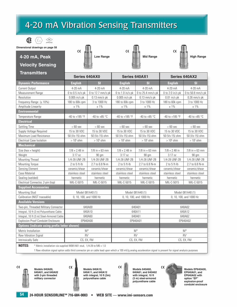
24-HOUR SENSORLINESM 716-684-0003 • WEB SITE — www.imi-sensors.com
4-20 mA Vibration Sensing Transmitters4-20 mA Vibration Sensing Transmitters
54
Series 640AX0 Series 640AX1 Series 640AX2
Dynamic Performance English SI English SI English SICurrent Output 4-20 mA 4-20 mA 4-20 mA 4-20 mA 4-20 mA 4-20 mAMeasurement Range 0 to 0.5 in/s pk 0 to 12.7 mm/s pk 0 to 1.0 in/s pk 0 to 25.4 mm/s pk 0 to 2.0 in/s pk 0 to 50.8 mm/s pkResolution 0.005 in/s pk 0.13 mm/s pk 0.005 in/s pk 0.13 mm/s pk 0.01 in/s pk 0.26 mm/s pkFrequency Range (± 10%) 180 to 60k cpm 3 to 1000 Hz 180 to 60k cpm 3 to 1000 Hz 180 to 60k cpm 3 to 1000 HzAmplitude Linearity ± 1% ± 1% ± 1% ± 1% ± 1% ± 1%
EnvironmentalTemperature Range -40 to +185 °F -40 to +85 °C -40 to +185 °F -40 to +85 °C -40 to +185 °F -40 to +85 °C
ElectricalSettling Time < 60 sec < 60 sec < 60 sec < 60 sec < 60 sec < 60 secSupply Voltage Required 15 to 30 VDC 15 to 30 VDC 15 to 30 VDC 15 to 30 VDC 15 to 30 VDC 15 to 30 VDCMaximum Load Resistance 50 (Vs-15) ohm 50 (Vs-15) ohm 50 (Vs-15) ohm 50 (Vs-15) ohm 50 (Vs-15) ohm 50 (Vs-15) ohmElectrical Case Isolation > 108 ohm > 108 ohm > 108 ohm > 108 ohm > 108 ohm > 108 ohm
MechanicalSize (hex × height) 7/8 × 2.48 in 7/8 in × 63 mm 7/8 × 2.48 in 7/8 in × 63 mm 7/8 × 2.48 in 7/8 in × 63 mmWeight 3.17 oz 90 gm 3.17 oz 90 gm 3.17 oz 90 gmMounting Thread 1/4-28 UNF-2B 1/4-28 UNF-2B 1/4-28 UNF-2B 1/4-28 UNF-2B 1/4-28 UNF-2B 1/4-28 UNF-2BMounting Torque 2 to 5 ft-lb 2.7 to 6.8 N-m 2 to 5 ft-lb 2.7 to 6.8 N-m 2 to 5 ft-lb 2.7 to 6.8 N-mSensing Element ceramic/shear ceramic/shear ceramic/shear ceramic/shear ceramic/shear ceramic/shearCase Material stainless steel stainless steel stainless steel stainless steel stainless steel stainless steelSealing (welded) hermetic hermetic hermetic hermetic hermetic hermeticElectrical Connector, 2-pin (top) MIL-C-5015 MIL-C-5015 MIL-C-5015 MIL-C-5015 MIL-C-5015 MIL-C-5015
Supplied AccessoriesMounting Stud Model 081A40 (1) Model 081A40 (1) Model 081A40 (1)Calibration (NIST traceable) 0, 10, 100, and 1000 Hz 0, 10, 100, and 1000 Hz 0, 10, 100, and 1000 Hz
Available VersionsTwo-pin, Threaded Military Connector 640A00 640A01 640A02Integral, 10 ft (3 m) Polyurethane Cable 640A10 640A11 640A12Integral, 10 ft (3 m) Steel-Armored Cable 640A60 640A61 640A62Explosion Proof Condulet Enclosure EP640A00 EP640A01 EP640A02
Options (indicate using prefix letter shown)Metric Installation M* M* M*Raw Vibration Signal RV† RV† RV†
Intrinsically Safe CS, EX, FM CS, EX, FM CS, EX, FM
NOTES: * Metric installation via supplied M081A61 stud, 1/4-28 to M6 × 1.0
† Raw vibration signal option adds third connector pin or cable lead upon which a 100 mV/g analog acceleration signal is present for signal analysis purposes
4-20 mA, Peak
Velocity Sensing
Transmitters
Models 640A60,640A61, and 640A62with integral, 10 ft(3 m) steel-armoredpolyurethane cable
Models 640A10,640A11, and 640A12with integral, 10 ft (3m)polyurethane cable
Models 640A00,640A01, and 640A02with 2-pin threaded military connector
Models EP640A00,EP640A01, andEP640A02 withoption “EP”explosion-proofcondulet enclosure
Low Range Mid Range High Range
Dimensional drawings on page 58

IMI SENSORS DIVISION TOLL-FREE � 800-959-4464
4-20 mA Vibration Sensing Transmitters4-20 mA Vibration Sensing Transmitters
55
Series 641AX0 Series 641AX1 Series 641AX2
Dynamic Performance English SI English SI English SICurrent Output 4-20 mA 4-20 mA 4-20 mA 4-20 mA 4-20 mA 4-20 mAMeasurement Range 0 to 0.5 in/s rms 0 to 12.7 mm/s rms 0 to 1.0 in/s rms 0 to 25.4 mm/s rms 0 to 2.0 in/s rms 0 to 50.8 mm/s rms
Resolution 0.005 in/s rms 0.13 mm/s rms 0.005 in/s rms 0.13 mm/s rms 0.01 in/s rms 0.26 mm/s rmsFrequency Range (± 10%) 600 to 60k cpm 10 to 1000 Hz 600 to 60k cpm 10 to 1000 Hz 600 to 60k cpm 10 to 1000 HzAmplitude Linearity ± 1% ± 1% ± 1% ± 1% ± 1% ± 1%
EnvironmentalTemperature Range -40 to +185 °F -40 to +85 °C -40 to +185 °F -40 to +85 °C -40 to +185 °F -40 to +85 °C
ElectricalSettling Time < 60 sec < 60 sec < 60 sec < 60 sec < 60 sec < 60 secSupply Voltage Required 15 to 30 VDC 15 to 30 VDC 15 to 30 VDC 15 to 30 VDC 15 to 30 VDC 15 to 30 VDCMaximum Load Resistance 50 (Vs-15) ohm 50 (Vs-15) ohm 50 (Vs-15) ohm 50 (Vs-15) ohm 50 (Vs-15) ohm 50 (Vs-15) ohmElectrical Case Isolation > 108 ohm > 108 ohm > 108 ohm > 108 ohm > 108 ohm > 108 ohm
MechanicalSize (hex × height) 7/8 × 2.48 in 7/8 in × 63 mm 7/8 × 2.48 in 7/8 in × 63 mm 7/8 × 2.48 in 7/8 in × 63 mmWeight 3.17 oz 90 gm 3.17 oz 90 gm 3.17 oz 90 gmMounting Thread 1/4-28 UNF-2B 1/4-28 UNF-2B 1/4-28 UNF-2B 1/4-28 UNF-2B 1/4-28 UNF-2B 1/4-28 UNF-2BMounting Torque 2 to 5 ft-lb 2.7 to 6.8 N-m 2 to 5 ft-lb 2.7 to 6.8 N-m 2 to 5 ft-lb 2.7 to 6.8 N-mSensing Element ceramic/shear ceramic/shear ceramic/shear ceramic/shear ceramic/shear ceramic/shearCase Material stainless steel stainless steel stainless steel stainless steel stainless steel stainless steelSealing (welded) hermetic hermetic hermetic hermetic hermetic hermeticElectrical Connector, 2-pin (top) MIL-C-5015 MIL-C-5015 MIL-C-5015 MIL-C-5015 MIL-C-5015 MIL-C-5015
Supplied AccessoriesMounting Stud Model 081A40 (1) Model 081A40 (1) Model 081A40 (1)Calibration (NIST traceable) 0, 10, 100, and 1000 Hz 0, 10, 100, and 1000 Hz 0, 10, 100, and 1000 Hz
Available VersionsTwo-pin, Threaded Military Connector 641A00 641A01 641A02Integral, 10 ft (3 m) Polyurethane Cable 641A10 641A11 641A12Integral, 10 ft (3 m) Steel-Armored Cable 641A60 641A61 641A62Explosion Proof Condulet Enclosure EP641A00 EP641A01 EP641A02
Options (indicate using prefix letter shown)Metric Installation M* M* M*Raw Vibration Signal RV† RV† RV†
Intrinsically Safe CS, EX, FM CS, EX, FM CS, EX, FM
NOTES: * Metric installation via supplied M081A61 stud, 1/4-28 to M6 × 1.0
† Raw vibration signal option adds third connector pin or cable lead upon which a 100 mV/g analog acceleration signal is present for signal analysis purposes
4-20 mA, RMS
Velocity Sensing
Transmitters
Models 641A60,641A61, and 641A62with integral, 10 ft (3 m) steel-armoredpolyurethane cable
Models 641A10,641A11, and 641A12with integral, 10 ft (3 m)polyurethane cable
Models EP641A00,EP641A01, andEP641A02 with option“EP” explosion-proof condulet enclosure
Models 641A00,641A01, and641A02 with 2-pinthreaded militaryconnector
Low Range Mid Range High Range
Dimensional drawings on page 58

24-HOUR SENSORLINESM 716-684-0003 • WEB SITE — www.imi-sensors.com
4-20 mA Vibration Sensing Transmitters4-20 mA Vibration Sensing Transmitters
56
Series 645AX0 Series 645AX1 Series 645AX2
Dynamic Performance English SI English SI English SICurrent Output 4-20 mA 4-20 mA 4-20 mA 4-20 mA 4-20 mA 4-20 mAMeasurement Range 0 to 5 g rms 0 to 49 m/s2 rms 0 to 5 g rms 0 to 49 m/s2 rms 0 to 5 g rms 0 to 49 m/s2 rmsResolution 0.025 g rms 0.24 m/s2 rms 0.025 g rms 0.24 m/s2 rms 0.025 g rms 0.24 m/s2 rmsFrequency Range (± 10%) 180 to 60k cpm 3 to 1000 Hz 180 to 300k cpm 3 to 5000 Hz 180 to 600k cpm 3 to 10k HzAmplitude Linearity ± 1% ± 1% ± 1% ± 1% ± 1% ± 1%
EnvironmentalTemperature Range -40 to +185 °F -40 to +85 °C -40 to +185 °F -40 to +85 °C -40 to +185 °F -40 to +85 °C
ElectricalSettling Time < 30 sec < 30 sec < 30 sec < 30 sec < 30 sec < 30 secSupply Voltage Required 15 to 30 VDC 15 to 30 VDC 15 to 30 VDC 15 to 30 VDC 15 to 30 VDC 15 to 30 VDCMaximum Load Resistance 50 (Vs-15) ohm 50 (Vs-15) ohm 50 (Vs-15) ohm 50 (Vs-15) ohm 50 (Vs-15) ohm 50 (Vs-15) ohmElectrical Case Isolation > 108 ohm > 108 ohm > 108 ohm > 108 ohm > 108 ohm > 108 ohm
MechanicalSize (hex × height) 7/8 × 2.48 in 7/8 in × 63 mm 7/8 × 2.48 in 7/8 in × 63 mm 7/8 × 2.48 in 7/8 in × 63 mmWeight 3.17 oz 90 gm 3.17 oz 90 gm 3.17 oz 90 gmMounting Thread 1/4-28 UNF-2B 1/4-28 UNF-2B 1/4-28 UNF-2B 1/4-28 UNF-2B 1/4-28 UNF-2B 1/4-28 UNF-2BMounting Torque 2 to 5 ft-lb 2.7 to 6.8 N-m 2 to 5 ft-lb 2.7 to 6.8 N-m 2 to 5 ft-lb 2.7 to 6.8 N-mSensing Element ceramic/shear ceramic/shear ceramic/shear ceramic/shear ceramic/shear ceramic/shearCase Material stainless steel stainless steel stainless steel stainless steel stainless steel stainless steelSealing (welded) hermetic hermetic hermetic hermetic hermetic hermeticElectrical Connector, 2-pin (top) MIL-C-5015 MIL-C-5015 MIL-C-5015 MIL-C-5015 MIL-C-5015 MIL-C-5015
Supplied AccessoriesMounting Stud Model 081A40 (1) Model 081A40 (1) Model 081A40 (1)Calibration (NIST traceable) 0, 10, 100, and 1000 Hz 0, 10, 100, 1000, and 5000 Hz 0, 10, 100, 1000, and 10k Hz
Available VersionsTwo-pin, Threaded Military Connector 645A00 645A01 645A02Integral, 10 ft (3 m) Polyurethane Cable 645A10 645A11 645A12Integral, 10 ft (3 m) Steel-Armored Cable 645A60 645A61 645A62Explosion Proof Condulet Enclosure EP645A00 EP645A01 EP645A02
Options (indicate using prefix letter shown)Metric Installation M* M* M*Raw Vibration Signal RV† RV† RV†
Intrinsically Safe CS, EX, FM CS, EX, FM CS, EX, FM
NOTES: * Metric installation via supplied M081A61 stud, 1/4-28 to M6 × 1.0
† Raw vibration signal option adds third connector pin or cable lead upon which a 100 mV/g analog acceleration signal is present for signal analysis purposes
4-20 mA, RMSAccelerationSensingTransmitters
Models 645A60,645A61, and 645A62with integral, 10 ft (3 m) steel-armoredpolyurethane cable
Models 645A10,645A11, and 645A12with integral, 10 ft (3 m)polyurethane cable
Models 645A00,645A01, and 645A02with 2-pin threaded military connector
Models EP645A00,EP645A01, andEP645A02 with option“EP” explosion-proofcondulet enclosure
Low RangeLow Frequency
Low RangeMid Frequency
Low RangeHigh Frequency
Dimensional drawings on page 58

IMI SENSORS DIVISION TOLL-FREE � 800-959-4464
4-20 mA Vibration Sensing Transmitters4-20 mA Vibration Sensing Transmitters
57
Series 646AX0 Series 646AX1 Series 646AX2
Dynamic Performance English SI English SI English SICurrent Output 4-20 mA 4-20 mA 4-20 mA 4-20 mA 4-20 mA 4-20 mAMeasurement Range 0 to 10 g rms 0 to 98.1 m/s2 rms 0 to 10 g rms 0 to 98.1 m/s2 rms 0 to 10 g rms 0 to 98.1 m/s2 rmsResolution 0.05 g rms 0.5 m/s2 rms 0.05 g rms 0.49 m/s2 rms 0.05 g rms 0.49 m/s2 rmsFrequency Range (± 10%) 180 to 60k cpm 3 to 1000 Hz 180 to 300k cpm 3 to 5k Hz 180 to 600k cpm 3 to 10k HzAmplitude Linearity ± 1% ± 1% ± 1% ± 1% ± 1% ± 1%
EnvironmentalTemperature Range -40 to +185 °F -40 to +85 °C -40 to +185 °F -40 to +85 °C -40 to +185 °F -40 to +85 °C
ElectricalSettling Time < 30 sec < 30 sec < 30 sec < 30 sec < 30 sec < 30 secSupply Voltage Required 15 to 30 VDC 15 to 30 VDC 15 to 30 VDC 15 to 30 VDC 15 to 30 VDC 15 to 30 VDCMaximum Load Resistance 50 (Vs-15) ohm 50 (Vs-15) ohm 50 (Vs-15) ohm 50 (Vs-15) ohm 50 (Vs-15) ohm 50 (Vs-15) ohmElectrical Case Isolation > 108 ohm > 108 ohm > 108 ohm > 108 ohm > 108 ohm > 108 ohm
MechanicalSize (hex × height) 7/8 × 2.48 in 7/8 in × 63 mm 7/8 × 2.48 in 7/8 in × 63 mm 7/8 × 2.48 in 7/8 in × 63 mmWeight 3.17 oz 90 gm 3.17 oz 90 gm 3.17 oz 90 gmMounting Thread 1/4-28 UNF-2B 1/4-28 UNF-2B 1/4-28 UNF-2B 1/4-28 UNF-2B 1/4-28 UNF-2B 1/4-28 UNF-2BMounting Torque 2 to 5 ft-lb 2.7 to 6.8 N-m 2 to 5 ft-lb 2.7 to 6.8 N-m 2 to 5 ft-lb 2.7 to 6.8 N-mSensing Element ceramic/shear ceramic/shear ceramic/shear ceramic/shear ceramic/shear ceramic/shearCase Material stainless steel stainless steel stainless steel stainless steel stainless steel stainless steelSealing (welded) hermetic hermetic hermetic hermetic hermetic hermeticElectrical Connector, 2-pin (top) MIL-C-5015 MIL-C-5015 MIL-C-5015 MIL-C-5015 MIL-C-5015 MIL-C-5015
Supplied AccessoriesMounting Stud Model 081A40 (1) Model 081A40 (1) Model 081A40 (1)Calibration (NIST traceable) 0, 10, 100, and 1000 Hz 0, 10, 100, 1000, and 5000 Hz 0, 10, 100, 1000, and 10k Hz
Available VersionsTwo-pin, Threaded Military Connector 646A00 646A01 646A02Integral, 10 ft (3 m) Polyurethane Cable 646A10 646A11 646A12Integral, 10 ft (3 m) Steel-Armored Cable 646A60 646A61 646A62Explosion Proof Condulet Enclosure EP646A00 EP646A01 EP646A02
Options (indicate using prefix letter shown)Metric Installation M* M* M*Raw Vibration Signal RV† RV† RV†
Intrinsically Safe CS, EX, FM CS, EX, FM CS, EX, FM
NOTES: * Metric installation via supplied M081A61 stud, 1/4-28 to M6 × 1.0
† Raw vibration signal option adds third connector pin or cable lead upon which a 100 mV/g analog acceleration signal is present for signal analysis purposes
4-20 mA, RMSAccelerationSensingTransmitters
Models 646A60,646A61, and 646A62with integral, 10 ft (3 m) steel-armoredpolyurethane cable
Models 646A10,646A11, and 646A12with integral, 10 ft (3 m)polyurethane cable
Models 645A00,645A01, and 645A02with 2-pin threaded military connector
Models EP646A00,EP646A01, adnEP646A02 with option“EP”explosion-proofcondulet enclosure
High RangeLow Frequency
High RangeMid Frequency
High RangeHigh Frequency
Dimensional drawings on page 58

24-HOUR SENSORLINESM 716-684-0003 • WEB SITE — www.imi-sensors.com
4-20 mA Vibration Sensing Transmitters4-20 mA Vibration Sensing Transmitters
58
Dimensions shown are in inches (millimeters).
Models 640A00, 640A01, 640A02Models 641A00, 641A01, 641A02Models 645A00, 645A01, 645A02Models 646A00, 646A01, 646A02
with 2-pin threaded military connector
Models EP640A60, EP640A61, EP640A62Models EP641A60, EP641A61, EP641A62Models EP645A60, EP645A61, EP645A62Models EP646A60, EP646A61, EP646A62with explosion proof condulet enclosure
Models 640A10, 640A11, 640A12Models 641A10, 641A11, 641A12Models 645A10, 645A11, 645A12Models 646A10, 646A11, 646A12
with integral, 10 ft (3 m) polyurethane cable
Models 640A60, 640A61, 640A62Models 641A60, 641A61, 641A62Models 645A60, 645A61, 645A62Models 646A60, 646A61, 646A62
with integral, 10 ft (3 m) steel-armored, polyurethane cable
Series 640AXX, 641AXX, 645AXX, 646AXX

DC Response, IndustrialCapacitive Accelerometers
DC Response, IndustrialCapacitive Accelerometers
59
PCB 716-684-0001 IMI Sensors Division toll-free 800-959-4464 Fax 716-684-3823 E-mail [email protected] Web site www.imi-sensors.com
Vibration measurements on slowrotating machinery
Paper machine rolls
Large structures and machinefoundations
Large fans and air handling equipment
Cooling towers
Buildings, bridges, foundations,and floors
Unlike piezoelectric accelerometers that have a low frequencylimit, industrial capacitive accelerometers are capable ofmeasuring to true DC, or 0 Hz.
These capacitive accelerometers utilize two opposed platecapacitors that share a common flexible plate. As the flexibleplate responds to acceleration, differential output signalsfrom the two capacitors are created. These signals are conditioned to reject common mode noise and combined toprovide a standardized output sensitivity. Built-in voltageregulation and optional low-power versions permits operationfrom a wide variety of DC power sources. The result is a sensorthat is easy to implement and delivers a high integrity, lownoise output signal.
DC response, industrial capacitive accelerometers offermany of the same advantages as IMI’s general purposeindustrial accelerometers including: rugged, laser-welded,stainless steel housing with the ability to endure dirty, wet, orharsh environments; hermetically sealed military connectoror sealed integral cable; and a low noise, low impedance,voltage output signal with long distance signal transmissioncapability.
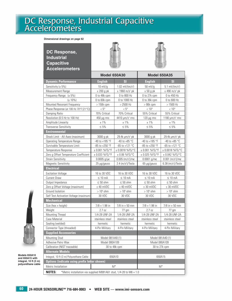
24-HOUR SENSORLINESM 716-684-0003 • WEB SITE — www.imi-sensors.com
DC Response, Industrial CapacitiveAccelerometersDC Response, Industrial CapacitiveAccelerometers
60
Model 650A30 Model 650A35
Dynamic Performance English SI English SISensitivity (± 5%) 10 mV/g 1.02 mV/(m/s2) 50 mV/g 5.1 mV/(m/s2)Measurement Range ± 200 g pk ± 1960 m/s2 pk ± 50 g pk ± 490 m/s2 pkFrequency Range: (± 5%) 0 to 48k cpm 0 to 800 Hz 0 to 27k cpm 0 to 450 Hz
(± 10%) 0 to 60k cpm 0 to 1000 Hz 0 to 36k cpm 0 to 600 HzMounted Resonant Frequency > 150k cpm > 2500 Hz > 90k cpm > 1500 HzPhase Response (at 100 Hz 70°F [21°C]) < 5° < 5° < 10° < 10°Damping Ratio 70% Critical 70% Critical 55% Critical 55% CriticalResolution (0.5 Hz to 100 Hz) 450 µg rms 4410 µm/s2 rms 120 µg rms 1180 µm/s2 rmsAmplitude Linearity ± 1% ± 1% ± 1% ± 1%Transverse Sensitivity ≤ 5% ≤ 5% ≤ 5% ≤ 5%
EnvironmentalShock Limit - All Axes (maximum) 3000 g pk 29.4k µm/s2 pk 3000 g pk 29.4k µm/s2 pkOperating Temperature Range -40 to +185 °F -40 to +85 °C -40 to +185 °F -40 to +85 °CSurvivable Temperature Limit -85 to +250 °F -65 to +121 °C -85 to +250 °F -65 to +121 °CTemperature Response ± 0.001 %FS/°F ± 0.0018 %FS/°C ± 0.001 %FS/°F ± 0.0018 %FS/°CZero g Offset Temperature Coefficient ± 0.033 %FS/°F ± 0.06 %FS/°C ± 0.025 %FS/°F ± 0.042 %FS/°C Strain Sensitivity 0.0005 g/µε 0.005 (m/s2)/mε 0.0001 g/mε 0.001 (m/s2)/mεMagnetic Sensitivity 25 µg/gauss 2.4 (m/s2)/Tesla 65 µg/gauss 6.38 (m/s2)/Tesla
ElectricalExcitation Voltage 16 to 30 VDC 16 to 30 VDC 16 to 30 VDC 16 to 30 VDCCurrent Draw ≤ 10 mA ≤ 10 mA ≤ 10 mA ≤ 10 mAOutput Impedance ≤ 50 ohm ≤ 50 ohm ≤ 50 ohm ≤ 50 ohmZero g Offset Voltage (maximum) ± 40 mVDC ± 40 mVDC ± 30 mVDC ± 30 mVDCGround Isolation > 108 ohm > 108 ohm > 108 ohm > 108 ohmSelf Test Activation Voltage (maximum) 30 VDC 30 VDC 30 VDC 30 VDC
MechanicalSize (hex × height) 7/8 × 1.98 in 7/8 in × 50 mm 7/8 × 1.98 in 7/8 in × 50 mmWeight 2.7 oz 77 gm 2.7 oz 77 gmMounting Thread 1/4-28 UNF-2A 1/4-28 UNF-2A 1/4-28 UNF-2A 1/4-28 UNF-2ACase Material stainless steel stainless steel stainless steel stainless steelSealing (welded) hermetic hermetic hermetic hermeticConnector Type (threaded) 4-Pin Military 4-Pin Military 4-Pin Military 4-Pin Military
Supplied AccessoriesMounting Stud Model 081A40 (1) Model 081A40 (1)Adhesive Petro Wax Model 080A109 Model 080A109Calibration (NIST traceable) 30 to 48k cpm 30 to 27k cpm
Alternate ModelsIntegral, 10 ft (3 m) Polyurethane Cable 650A10 650A15
Options (indicate using prefix letter shown)Metric Installation M* M*
NOTES: *Metric installation via supplied M081A61 stud, 1/4-28 to M6 × 1.0
Models 650A10 and 650A15 withintegral, 10 ft (3 m)polyurethane cable
DC Response,IndustrialCapacitiveAccelerometers
Dimensional drawings on page 62

IMI SENSORS DIVISION TOLL-FREE � 800-959-4464
DC Response, Industrial CapacitiveAccelerometers
DC Response, Industrial CapacitiveAccelerometers
61
Model 650A31 Model 650A34
Dynamic Performance English SI English SISensitivity (± 5%) 100 mV/g 10.2 mV/(m/s2) 1000 mV/g 102 mV/(m/s2)Measurement Range ± 20 g pk ± 196 m/s2 pk ± 3 g pk ± 29 m/s2 pkFrequency Range: (± 5%) 0 to 18k cpm 0 to 300 Hz 0 to 6000 cpm 0 to 100 Hz
(± 10%) 0 to 30k cpm 0 to 500 Hz 0 to 9000 cpm 0 to 150 HzMounted Resonant Frequency > 54k cpm > 1900 Hz > 24k cpm > 400 HzPhase Response (at 100 Hz 70°F [21°C]) < 10° < 10° < 3° < 3°Damping Ratio 70% Critical 70% Critical 85% Critical 85% CriticalResolution (0.5 Hz to 100 Hz) 80 µg rms 800 µm/s2 rms 30 µg rms 295 µm/s2 rmsAmplitude Linearity ± 1% ±1% ± 1% ± 1%Transverse Sensitivity ≤ 5% ≤ 5% ≤ 5% ≤ 5%
EnvironmentalShock Limit - All Axes (maximum) 3000 g pk 29.4k µm/s2 pk 3000 g pk 29.4k µm/s2 pkOperating Temperature Range -40 to +185 °F -40 to +85 °C -40 to +185 °F -40 to +85 °CSurvivable Temperature Limit -85 to +250 °F -65 to +121 °C -85 to +250 °F -65 to +121 °CTemperature Response ± 0.0025 %FS/°F ± 0.0045 %FS/°C ± 0.017 %FS/°F ± 0.03 %FS/°CZero g Offset Temperature Coefficient ± 0.14 %FS/°F ± 0.25 %FS/°C ± 0.04 %FS/°F ± 0.72 %FS/°C Strain Sensitivity 0.0001 g/µε 0.001 (m/s2)/mε 0.0002 g/mε 0.002 (m/s2)/mεMagnetic Sensitivity 65 µg/gauss 6.38 (m/s2)/Tesla 25 µg/gauss 2.4 (m/s2)/Tesla
ElectricalExcitation Voltage 16 to 30 VDC 16 to 30 VDC 16 to 30 VDC 16 to 30 VDCCurrent Draw ≤ 10 mA ≤ 10 mA ≤ 10 mA ≤ 10 mAOutput Impedance ≤ 50 ohm ≤ 50 ohm ≤ 50 ohm ≤ 50 ohmZero g Offset Voltage (maximum) ± 40 mVDC ± 40 mVDC ± 200 mVDC ± 200 mVDCGround Isolation > 108 ohm > 108 ohm > 108 ohm > 108 ohmSelf Test Activation Voltage (maximum) 30 VDC 30 VDC 30 VDC 30 VDC
MechanicalSize (hex × height) 7/8 × 1.98 in 7/8 in × 50 mm 7/8 × 1.98 in 7/8 in × 50 mmWeight 2.7 oz 77 gm 2.7 oz 77 gmMounting Thread 1/4-28 UNF-2A 1/4-28 UNF-2A 1/4-28 UNF-2A 1/4-28 UNF-2ACase Material stainless steel stainless steel stainless steel stainless steelSealing (welded) hermetic hermetic hermetic hermeticConnector Type (threaded) 4-Pin Military 4-Pin Military 4-Pin Military 4-Pin Military
Supplied AccessoriesMounting Stud Model 081A40 (1) Model 081A40 (1)Adhesive Petro Wax Model 080A109 Model 080A109Calibration (NIST traceable) 30 to 18k cpm 30 to 6k cpm
Alternate ModelsIntegral, 10 ft (3 m) Polyurethane Cable 650A11 650A14
Options (indicate using prefix letter shown)Metric Installation M* M*
NOTES: *Metric installation via supplied M081A61 stud, 1/4-28 to M6 × 1.0
DC Response,IndustrialCapacitiveAccelerometers
Dimensional drawings on page 62
Models 650A11 and 650A14 withintegral, 10 ft (3 m)polyurethane cable
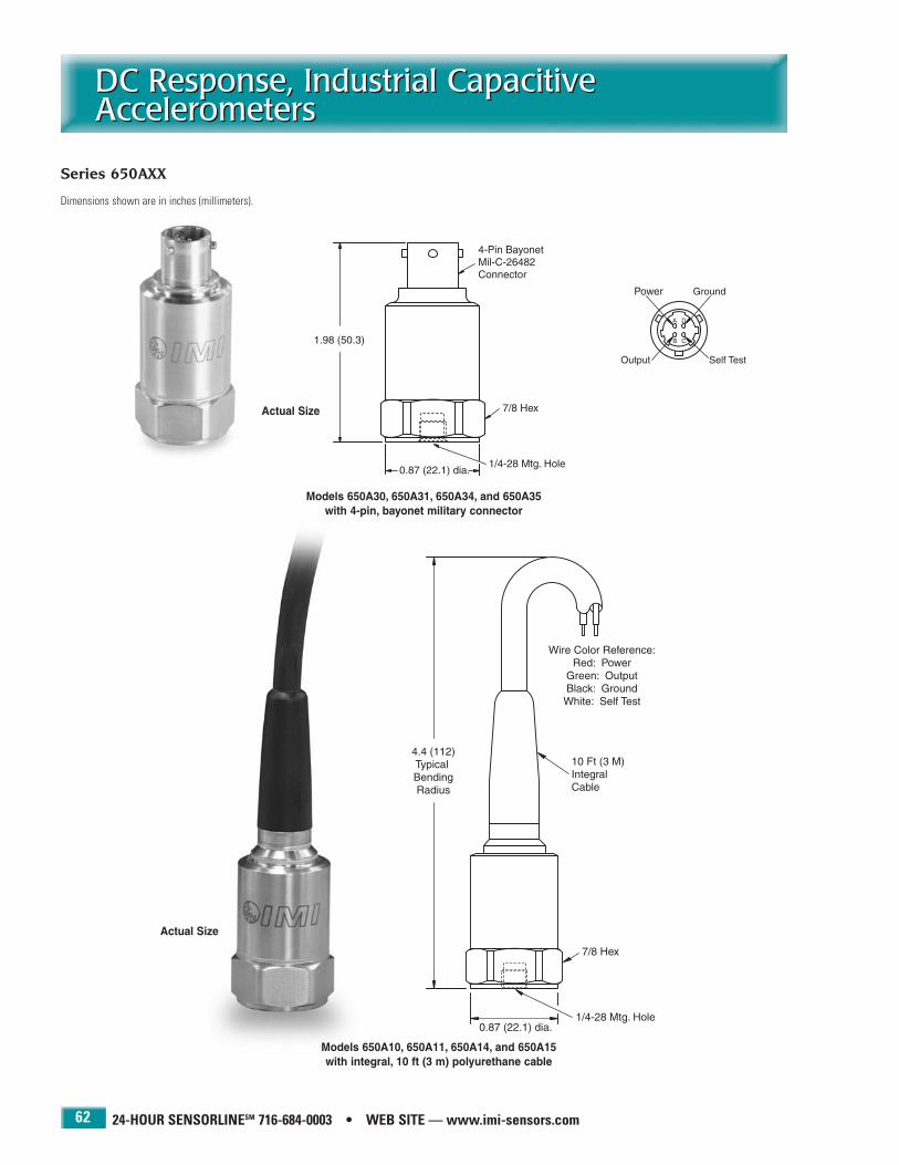
24-HOUR SENSORLINESM 716-684-0003 • WEB SITE — www.imi-sensors.com
DC Response, Industrial CapacitiveAccelerometersDC Response, Industrial CapacitiveAccelerometers
62
Models 650A30, 650A31, 650A34, and 650A35with 4-pin, bayonet military connector
Series 650AXX
Actual Size
Actual Size
Models 650A10, 650A11, 650A14, and 650A15with integral, 10 ft (3 m) polyurethane cable
Dimensions shown are in inches (millimeters).

Impact HammersImpact Hammers
63
PCB 716-684-0001 IMI Sensors Division toll-free 800-959-4464 Fax 716-684-3823 E-mail [email protected] Web site www.imi-sensors.com
Modal analysis
Structural testing
Impulse and response
Resonance determination
Laboratory design test evaluation
Civil structure health determination
Resonance testing and modal analysis are excellent root-cause failure analysis techniques. Impacting a structureexcites it with a broadband force. This excitation causes thestructure or machine to vibrate at its natural or resonant frequencies. Through the use of a two-channel data collectorthat measures the ratio of the vibratory response (typicallymeasured with an accelerometer) to the input force (generatedand measured with an impact hammer), a frequencyresponse function (FRF) results, which identifies problem resonances. IMI’s Modally Tuned® Impact Hammers are ideally suited for this type of testing.
A selection of tips are included with each hammer. Whenused with an extender mass, the hammer can be tailored todeliver the desired frequency content of the impulse forcewaveform on the structure being tested.
Modally Tuned® Impact Hammers have been proven over thousands of requirements in such applications as automotivedesign, bridge health assessment, and aerospace vehicle development. Their design has been refined, through the selection of their materials of construction, to deliver consistent,accurate results. This “modal tuning” of the hammer structure eliminates hammer resonances from corrupting the test data,resulting in more accurate test results.
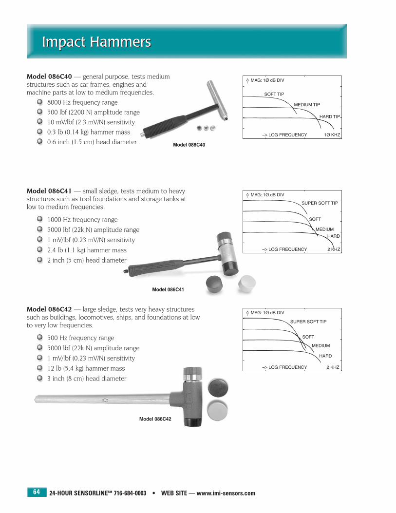
24-HOUR SENSORLINESM 716-684-0003 • WEB SITE — www.imi-sensors.com
Impact HammersImpact Hammers
64
Model 086C41
Model 086C42
Model 086C40
Model 086C40 — general purpose, tests medium structures such as car frames, engines and machine parts at low to medium frequencies.
8000 Hz frequency range500 lbf (2200 N) amplitude range10 mV/lbf (2.3 mV/N) sensitivity0.3 lb (0.14 kg) hammer mass0.6 inch (1.5 cm) head diameter
Model 086C41 — small sledge, tests medium to heavy structures such as tool foundations and storage tanks at low to medium frequencies.
1000 Hz frequency range
5000 lbf (22k N) amplitude range
1 mV/lbf (0.23 mV/N) sensitivity
2.4 lb (1.1 kg) hammer mass
2 inch (5 cm) head diameter
Model 086C42 — large sledge, tests very heavy structuressuch as buildings, locomotives, ships, and foundations at lowto very low frequencies.
500 Hz frequency range
5000 lbf (22k N) amplitude range
1 mV/lbf (0.23 mV/N) sensitivity
12 lb (5.4 kg) hammer mass
3 inch (8 cm) head diameter

IMI SENSORS DIVISION TOLL-FREE � 800-959-4464
Impact HammersImpact Hammers
65
Model 086C40 Model 086C41 Model 086C42
Dynamic Performance English SI English SI English SIFrequency Range 8000 Hz 8000 Hz 1000 Hz 1000 Hz 500 Hz 500 HzAmplitude Range 500 lbf 2200 N 5000 lbf 22k N 5000 lbf 22k NVoltage Sensitivity 10 mV/lbf 2.3 mV/N 1 mV/lbf 0.23 mV/N 1 mV/lbf 0.23 mV/NResonant Frequency 31k Hz 31k Hz 12k Hz 12k Hz 2700 Hz 2700 Hz
MechanicalMass (without extender) 0.3 lb 0.14 kg 2.4 lb 1.1 kg 12.1 lb 5.4 kgHead Diameter 0.6 in 1.5 cm 2 in 5 cm 3 in 8 cmTip Diameter 0.25 in 0.63 cm 2 in 5 cm 3 in 8 cmHandle Length (nominal) 8 in 20.3 cm 14.5 in 36.8 cm 35 in 89 cmElectrical Connector BNC jack BNC jack BNC jack BNC jack BNC jack BNC jack
Supplied AccessoriesSuper Soft Tip Model 084B11 084A60 084A30Soft Tip Model 084B05 084A61 084A31Medium Tip Model 084B04 084A62 084A32Hard Tip Model 084B03 084A63 084A33Extender Model 084A08 — —Extender Mounting Stud 081B05 — —Carry Case Model 001A02 001A11 001A16NIST Traceable Calibration to 10k Hz to 2000 Hz to 2000 Hz
Modally Tuned®
ICP® ImpactHammers

24-HOUR SENSORLINESM 716-684-0003 • WEB SITE — www.imi-sensors.com
Industrial Accelerometer ApplicationsIndustrial Accelerometer Applications
66
IMI has grown to become a world leading manufacturer of industrial accelerometers andaccessories. Our customers encompass manyindustries and utilize a broad product offering tosatisfy the demands of a variety of industrialmachinery monitoring applications.

Dynamic Pressure SensorsDynamic Pressure Sensors
67
PCB 716-684-0001 IMI Sensors Division toll-free 800-959-4464 Fax 716-684-3823 E-mail [email protected] Web site www.imi-sensors.com
Slurry pulsations
Pump testing
Compressor studies
Water hammer investigations
Leak detection
Pressure surges and spikes
Dynamic pressures in process systems and plant piping cancause inconsistencies in final products or damage to equipmentand instrumentation. Such pressure spikes, surges, and pulsations, may go unnoticed by conventional industrialpressure transmitters or piezoresistive sensors. Piezoelectricpressure sensors, on the other hand, possess the uniquecharacteristics required to detect and measure such dynamicphenomena.
Dynamic pressure sensors can be an invaluable resource inthe maintenance technician’s toolbox for determining andtroubleshooting root causes in both pneumatic and fluidhandling systems.

24-HOUR SENSORLINESM 716-684-0003 • WEB SITE — www.imi-sensors.com
Dynamic ICP® Pressure SensorsDynamic ICP® Pressure Sensors
68
Model 671A01 ICP® Paper Slurry Pulsation Sensor
Detect and monitor headbox and pipingsystem pressure pulsations
Assists with troubleshooting slurry flow irregularities to improve product consistency
Installs through check valve to precisedepth to maintain flush mounting
High output quartz sensing element
300 mV/psi (43.5 mV/kPa) sensitivity
2-pin military connector
Series 121A ICP® Industrial Dynamic Pressure Sensor
Monitor and troubleshoot compressorand pumping systems
Water hammer detection
Leak detection
Integral cable or 2-pin MIL connector
Choice of 100, 1000, and 5000 psi ranges
Model 671A01with 2-pin, threaded military connector
Dimensions shown are in inches (millimeters).
Series 121Awith 2-pin, threaded military connector or
integral, 10 ft (3 m) polyurethane cable
Model 121A21 - 100 psi (689 kPa) rangeModel 121A22 - 1000 psi (6895 kPa) rangeModel 121A23 - 5000 psi (34,473 kPa) range
Model 121A31 - 100 psi (689 kPa) rangeModel 121A32 - 1000 psi (6895 kPa) rangeModel 121A33 - 5000 psi (34,473 kPa) range
Dimensions shown are in inches (millimeters).

69
PCB 716-684-0001 IMI Sensors Division toll-free 800-959-4464 Fax 716-684-3823 E-mail [email protected] Web site www.imi-sensors.com
Switch Boxes, Interface Boxes, and Enclosures
Switch Boxes, Interface Boxes, and Enclosures
BNC Termination boxes
Switch boxes
Interface boxes
Junction boxes
BNC Termination Boxes, Switch Boxes, and Junction Boxes assistwith data collection by terminating cables of permanentlyinstalled sensors at convenient, safe, data collection locations.
Termination boxes and switch boxes do not contain powersupplies, rather they rely on transferring excitation powerprovided by vibration data collectors or signal conditionersto connected sensors. Since excitation power is presented toeach sensor when its measurement channel is selected, thesensor’s settling time (or turn-on time) must be overcomeprior to taking measurements. Alternatively, junction boxesincorporate a power supply and provide ICP® sensor excitationto all connected sensors simultaneously, allowing faster datacollection since the settling time of the sensor need not beovercome after channel selection.
Interface Boxes aid in reducing cable costs by convertingindividual sensor wires to multi-conductor cables for longerdistance cable runs. Interface Boxes are typically installed in-between accelerometers and Junction Boxes.
The multiple output (MO) option available on some switchboxes and junction boxes allows direct access to all inputchannels simultaneously. This feature permits use with, orfuture upgrade to, continuous, on-line monitoring systemmultiplexors.
Model 691B4716-Channel Switch BoxInterfaces permanently installed vibrationsensors with data collection equipment.

24-HOUR SENSORLINESM 716-684-0003 • WEB SITE — www.imi-sensors.com70
Small BNC Termination BoxesSmall BNC Termination Boxes
Series 691A51
Small BNC termination boxes offer a simple, economical,and safe method for accessing up to 4 sensors that areinstalled in remote locations. Each features a wallmountable, fiberglass, NEMA-4X (IP65) enclosure; aninternal terminal strip for connection to pigtailed sensorcables; and externally mounted BNC jack connectorsfor interface to data collection equipment. BNC termi-nation boxes do not supply sensor excitation power.
Simply connect a data collector, with sensor excitationpower, to the BNC jack of the sensor channel of interestto access that sensor's measurement signal.
1/2 Actual Size
Series 691A51 Specifications
Models Available in this Series Number of ChannelsModel 691A51/01 1Model 691A51/02 2Model 691A51/03 3Model 691A51/04 4
Electrical English SINo Active Electrical ComponentsNo Power Required
MechanicalInput Connector terminal strip terminal stripOutput Connector(s) BNC jack BNC jackInput Cable Cord Grip(s) PGME7 PGME7Enclosure Material fiberglass fiberglassSize (h x w x d) 2.95 x 5.27 x 2.16 in 75 x 134 x 55 mm
EnvironmentalEnclosure Environmental Rating NEMA 4X IP66
Model 691A51/04 shownBNC Termination Box
Dimensions shown are in inches (millimeters).

IMI SENSORS DIVISION TOLL-FREE � 800-959-4464 71
BNC Termination EnclosuresBNC Termination Enclosures
Series 691A50
BNC termination enclosures offer a simple, economical,and safe method for accessing up to 12 sensors thatare installed in remote locations. Each features a wallmountable, fiberglass NEMA-4X (IP66) enclosure; aninternal terminal strip for connection to pigtailed sensorcables; and internally mounted BNC jack connectorsfor interface to data collection equipment. BNC termination enclosures do not supply sensor excitationpower.
Simply open the enclosure door and connect a datacollector, with sensor excitation power, to the BNC jackof the sensor channel of interest to access that sensor'smeasurement signal. Optional painted steel NEMA-12(IP65) and stainless steel NEMA-4X (IP66) enclosuresare also available.
Model 691A50/12 shownBNC Termination Enclosure
Dimensions shown are in inches (millimeters).
Series 691A50 Specifications
Models Available in this Series Number of ChannelsModel 691A50/01 1Model 691A50/02 2Model 691A50/03 3Model 691A50/04 4Model 691A50/05 5Model 691A50/06 6Model 691A50/07 7Model 691A50/08 8Model 691A50/09 9Model 691A50/10 10Model 691A50/11 11Model 691A50/12 12
Electrical English SINo Active Electrical Components
No Power Required
MechanicalInput Connector terminal strip terminal stripOutput Connector(s) BNC jack BNC jackInput Cable Cord Grip(s) PGME7 PGME7Enclosure Material fiberglass fiberglassSize (h x w x d) 8 x 6 x 4 in 203 x 152 x 102 mmWeight 2.5 lb 1.14 kg
EnvironmentalEnclosure Environmental Rating NEMA 4X IP66
Supplied AccessoriesMounting Hardware Kit
Options (indicate using prefix letter shown)PS — Painted Steel Enclosure
Type Nema 12 IP65Weight 5 lb 2.27 kg
SS — Stainless Steel EnclosureType Nema 4x IP66Weight 5.5 lb 2.5 kg
NOTES: For PS and SS options, mounting hardware is not included. It is integralto the construction of the box.
1/4 Actual Size

24-HOUR SENSORLINESM 716-684-0003 • WEB SITE — www.imi-sensors.com
Switch BoxesSwitch Boxes
72
Model 691B41
This six-channel switch box assists with route-baseddata collection by terminating the cables of permanentlyinstalled sensors at convenient, safe, data collectionlocations.
The unit does not contain a power supply, rather itrelies on transferring excitation power provided by thevibration data collector or signal conditioner to connected sensors. Since excitation power is presentedto each sensor when its measurement channel is selected,the sensor’s settling time (or turn-on time) must beovercome prior to taking measurements.
The Model 691B41 is available with a variety of cord gripoptions. When cord grips are ordered, the enclosure willbe provided with holes drilled for the appropriate cordgrips. If no cord grips are ordered, the enclosure is provided without drilled holes.
Model 691B41 Six-Channel Switch Box
Electrical English SIChannels 6 6
MechanicalInput Connectors terminal strip terminal stripOutput Connectors (vibration) BNC jack BNC jackOutput Connectors (temperature) BNC jack BNC jackEnclosure Material fiberglass fiberglassSize (h x w x d) 8 x 6 x 4 in 203 x 152 x 102 mmWeight 5 lb 2.3 kg
EnvironmentalEnclosure Environmental Rating NEMA 4X IP66
Supplied AccessoriesMounting Kit4 Socket Plug (100-3748-60)
Optional Accessories (order separately with model shown)Model 691010 6 individual cord grips, PGME07Model 691011 1 individual cord grip, PGME29Model 691012 1 individual cord grip, PGME13Model 691013 1 conduit fitting, 1.5 in
Options (indicate using prefix letter shown)PS — Painted Steel Enclosure
Type Nema 12 IP65Weight 7 lb 3.2 kg
SS — Stainless Steel EnclosureWeight 8 lb 3.6 kg
NOTES: For PS and SS options, mounting hardware is not included. It is integralto the construction of the box.
Model 691B416-Channel Switch Box
Dimensions shown are in inches (millimeters).
1/4 Actual Size

IMI SENSORS DIVISION TOLL-FREE � 800-959-4464
Switch BoxesSwitch Boxes
73
Model 691B42
This twelve-channel switch box assists with route-based data collection by the terminating cables of permanently installed sensors at convenient, safe, datacollection locations.
The unit does not contain a power supply, rather itrelies on transferring excitation power provided by thevibration data collector or signal conditioner to connected sensors. Since excitation power is presentedto each sensor when its measurement channel isselected, the sensor’s settling time (or turn-on time)must be overcome prior to taking measurements.
The Model 691B42 is available with a variety of cord gripoptions. When cord grips are ordered, the enclosure willbe provided with holes drilled for the appropriate cordgrips. If no cord grips are ordered, the enclosure isprovided without drilled holes.
Model 691B42 Twelve-Channel Switch Box
Electrical English SIChannels 12 12
MechanicalInput Connectors terminal strip terminal stripOutput Connectors (vibration) BNC jack BNC jackOutput Connectors (temperature) BNC jack BNC jackEnclosure Material fiberglass fiberglassSize (h x w x d) 8 x 6 x 4 in 203 x 152 x 102 mmWeight 5 lb 2.3 kg
EnvironmentalEnclosure Environmental Rating NEMA 4X IP66
Supplied AccessoriesMounting Kit4 Socket Plug (100-3748-60)
Optional Accessories (order separately with model shown)Model 691020 12 individual cord grips, PGME07Model 691021 2 individual cord grips, PGME29Model 691022 2 individual cord grips, PGME13Model 691023 1 individual cord grip, PGME36Model 691024 1 individual cord grip, PGME21Model 691025 1 conduit fitting, 1.5 inModel 691026 2 conduit fittings, 1.5 inModel 691027 1 individual cord grip, PGME29
Options (indicate using prefix letter shown)PS — Painted Steel Enclosure
Type Nema 12 IP65Weight 7 lb 3.2 kg
SS — Stainless Steel EnclosureWeight 8 lb 3.6 kg
NOTES: For PS and SS options, mounting hardware is not included. It is integralto the construction of the box.
Model 691B4212-Channel Switch Bzox
Dimensions shown are in inches (millimeters).
1/4 Actual Size

24-HOUR SENSORLINESM 716-684-0003 • WEB SITE — www.imi-sensors.com
Switch BoxesSwitch Boxes
74
Model 691B47
This sixteen-channel switch box assists with route-based data collection by terminating cables of permanently installed sensors at convenient, safe, datacollection locations.
The unit does not contain a power supply, rather itrelies on transferring excitation power provided by thevibration data collector or signal conditioner to connected sensors. Since excitation power is presentedto each sensor when its measurement channel isselected, the sensor’s settling time (or turn-on time)must be overcome prior to taking measurements.
The Model 691B47 is available with a variety of cord gripoptions. When cord grips are ordered, the enclosure willbe provided with holes drilled for the appropriate cordgrips. If no cord grips are ordered, the enclosure is provided without drilled holes.
Model 691B4716-Channel Switch Box
Dimensions shown are in inches (millimeters).
Model 691B47 Sixteen-Channel Switch Box
Electrical English SIChannels 16 16
MechanicalInput Connectors terminal strip terminal stripOutput Connectors (vibration) BNC jack BNC jackOutput Connectors multiple output multiple outputEnclosure Material fiberglass fiberglassSize (h x w x d) 10 x 8 x 6 in 254 x 203 x 152 mmWeight 4.4 lb 2.0 kg
EnvironmentalEnclosure Environmental Rating NEMA 4X IP66
Supplied AccessoriesMounting Kit3 Socket Plug (2)
Optional Accessories (order separately with model shown)Model 691070 16 individual cord grips, PGME07Model 691071 2 individual cord grips, PGME29
Options (indicate using prefix letter shown)SS — 304 Stainless Steel Enclosure
Size (h x w x d) 10 x 8 x 4 in 254 x 203 x 102 mmWeight 8.4 lb 3.9 kg
XSS — 316L Stainless Steel EnclosureSize (h x w x d) 10 x 8 x 4 in 254 x 203 x 102 mmWeight 9.2 lb 4.2 kg
NOTES: For PS and SS options, mounting hardware is not included. It is integralto the construction of the box.
1/5 Actual Size

Model 691B46 48-Channel Switch Boxwith four Model 691B40 12-Channel Switch Box
Modules installed in a fiberglass enclosure
IMI SENSORS DIVISION TOLL-FREE � 800-959-4464
Switch BoxesSwitch Boxes
75
Series 691B4X
This series of switch boxes offers a simple, economical,and safe method for accessing up to 48 sensors thatare installed in remote locations.
The Model 691B40 switch box module (without enclosure)featured on this page, is available separately, for fieldexpansion of the switch boxes, shown on the next 2pages. Alternatively, any number of these modules maybe installed in user supplied enclosures.
Each switch box features a wall mountable, fiberglassNEMA-4X (IP66) enclosure, internal terminal strip(s) forconnection to pigtailed sensor cables, sensor locationindex chart, internal rotary selector switch(es), andinternally mounted BNC jack connectors for interfaceto data collection equipment.
These units do not contain power supplies, rather theyrely on transferring excitation power provided by the vibration data collector or signal conditioner to connected sensors. Since excitation power is presentedto each sensor when its measurement channel isselected, the sensor’s settling time (or turn-on time)must be overcome prior to taking measurements.
Optional painted steel NEMA-12 (IP65) and stainlesssteel NEMA-4X (IP66) enclosures are also available.
Model 691B4012-Channel Switch Box Module
Dimensions shown are in inches (millimeters).
1/3 Actual Size
Model 691B40 Switch Box Module
Electrical English SIChannels 12 12
MechanicalInput Connectors terminal strip terminal stripOutput Connectors (vibration) BNC jack BNC jackOutput Connectors (temperature) BNC jack BNC jackSize (h x w x d) 7.3 x 5.5 x 3.3 in 186 x 140 x 54 mmWeight 1.7 lb 0.8 kg
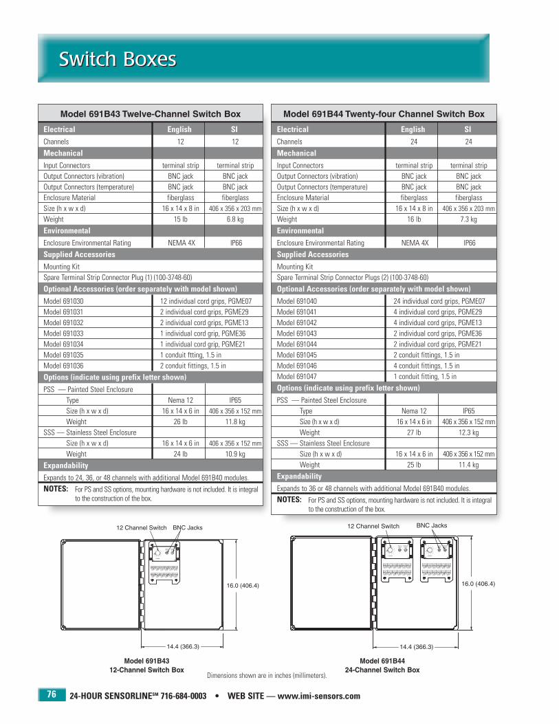
24-HOUR SENSORLINESM 716-684-0003 • WEB SITE — www.imi-sensors.com
Switch BoxesSwitch Boxes
76
Model 691B43 Twelve-Channel Switch Box
Electrical English SIChannels 12 12
MechanicalInput Connectors terminal strip terminal stripOutput Connectors (vibration) BNC jack BNC jackOutput Connectors (temperature) BNC jack BNC jackEnclosure Material fiberglass fiberglassSize (h x w x d) 16 x 14 x 8 in 406 x 356 x 203 mmWeight 15 lb 6.8 kg
EnvironmentalEnclosure Environmental Rating NEMA 4X IP66
Supplied AccessoriesMounting KitSpare Terminal Strip Connector Plug (1) (100-3748-60)
Optional Accessories (order separately with model shown)Model 691030 12 individual cord grips, PGME07Model 691031 2 individual cord grips, PGME29Model 691032 2 individual cord grips, PGME13Model 691033 1 individual cord grip, PGME36Model 691034 1 individual cord grip, PGME21Model 691035 1 conduit ftting, 1.5 inModel 691036 2 conduit fittings, 1.5 in
Options (indicate using prefix letter shown)PSS — Painted Steel Enclosure
Type Nema 12 IP65Size (h x w x d) 16 x 14 x 6 in 406 x 356 x 152 mmWeight 26 lb 11.8 kg
SSS — Stainless Steel EnclosureSize (h x w x d) 16 x 14 x 6 in 406 x 356 x 152 mmWeight 24 lb 10.9 kg
ExpandabilityExpands to 24, 36, or 48 channels with additional Model 691B40 modules.NOTES: For PS and SS options, mounting hardware is not included. It is integral
to the construction of the box.
Model 691B44 Twenty-four Channel Switch Box
Electrical English SIChannels 24 24
MechanicalInput Connectors terminal strip terminal stripOutput Connectors (vibration) BNC jack BNC jackOutput Connectors (temperature) BNC jack BNC jackEnclosure Material fiberglass fiberglassSize (h x w x d) 16 x 14 x 8 in 406 x 356 x 203 mmWeight 16 lb 7.3 kg
EnvironmentalEnclosure Environmental Rating NEMA 4X IP66
Supplied AccessoriesMounting KitSpare Terminal Strip Connector Plugs (2) (100-3748-60)
Optional Accessories (order separately with model shown)Model 691040 24 individual cord grips, PGME07Model 691041 4 individual cord grips, PGME29Model 691042 4 individual cord grips, PGME13Model 691043 2 individual cord grips, PGME36Model 691044 2 individual cord grips, PGME21Model 691045 2 conduit fittings, 1.5 inModel 691046 4 conduit fittings, 1.5 inModel 691047 1 conduit fitting, 1.5 in
Options (indicate using prefix letter shown)PSS — Painted Steel Enclosure
Type Nema 12 IP65Size (h x w x d) 16 x 14 x 6 in 406 x 356 x 152 mmWeight 27 lb 12.3 kg
SSS — Stainless Steel EnclosureSize (h x w x d) 16 x 14 x 6 in 406 x 356 x 152 mmWeight 25 lb 11.4 kg
ExpandabilityExpands to 36 or 48 channels with additional Model 691B40 modules.NOTES: For PS and SS options, mounting hardware is not included. It is integral
to the construction of the box.
Model 691B4312-Channel Switch Box
Model 691B4424-Channel Switch Box
Dimensions shown are in inches (millimeters).

IMI SENSORS DIVISION TOLL-FREE � 800-959-4464
Switch BoxesSwitch Boxes
77
Model 691B45 Thirty-six Channel Switch Box
Electrical English SIChannels 36 36
MechanicalInput Connectors terminal strip terminal stripOutput Connectors (vibration) BNC jack BNC jackOutput Connectors (temperature) BNC jack BNC jackEnclosure Material fiberglass fiberglassEnclosure Material fiberglass fiberglassSize (h x w x d) 16 x 14 x 8 in 406 x 356 x 203 mmWeight 17 lb 7.7 kg
EnvironmentalEnclosure Environmental Rating NEMA 4X IP66
Supplied AccessoriesMounting KitSpare Terminal Strip Connector Plugs (3) (100-3748-60)
Optional Accessories (order separately with model shown)Model 691050 36 individual cord grips, PGME07Model 691051 6 individual cord grips, PGME29Model 691052 6 individual cord grips, PGME13Model 691053 3 individual cord grips, PGME36Model 691054 3 individual cord grips, PGME21Model 691055 3 conduit fittings, 1.5 inModel 691056 6 conduit fittings, 1.5 in
Options (indicate using prefix letter shown)PSS — Painted Steel Enclosure
Type Nema 12 IP65Size (h x w x d) 16 x 14 x 6 in 406 x 356 x 152 mmWeight 28 lb 12.7 kg
SSS — Stainless Steel EnclosureSize (h x w x d) 16 x 14 x 6 in 406 x 356 x 152 mmWeight 26 lb 11.8 kg
ExpandabilityExpands to 48 channels with an additional Model 691B40 moduleNOTES: For PS and SS options, mounting hardware is not included. It is integral
to the construction of the box.
Model 691B46 Forty-eight Channel Switch Box
Electrical English SIChannels 48 48
MechanicalInput Connectors terminal strip terminal stripOutput Connectors (vibration) BNC jack BNC jackOutput Connectors (temperature) BNC jack BNC jackEnclosure Material fiberglass fiberglassEnclosure Material fiberglass fiberglassSize (h x w x d) 16 x 14 x 8 in 406 x 356 x 203 mmWeight 18 lb 8.2 kg
EnvironmentalEnclosure Environmental Rating NEMA 4X IP66
Supplied AccessoriesMounting KitSpare Terminal Strip Connector Plugs (4) (100-3748-60)
Optional Accessories (order separately with model shown)Model 691060 48 individual cord grips, PGME07Model 691061 8 individual cord grips, PGME29Model 691062 8 individual cord grips, PGME13Model 691063 4 individual cord grips, PGME36Model 691064 4 individual cord grips, PGME21Model 691065 4 conduit fittings, 1.5 inModel 691066 8 conduit fittings, 1.5 in
Options (indicate using prefix letter shown)PSS — Painted Steel Enclosure
Type Nema 12 IP65Size (h x w x d) 16 x 14 x 6 in 406 x 356 x 152 mmWeight 29 lb 13.2 kg
SSS — Stainless Steel EnclosureSize (h x w x d) 16 x 14 x 6 in 406 x 356 x 152Weight 27 lb 12.3 kg
NOTES: For PS and SS options, mounting hardware is not included. It is integralto the construction of the box.
Model 691B4536-Channel Switch Box
Model 691B4648-Channel Switch BoxDimensions shown are in inches (millimeters).

24-HOUR SENSORLINESM 716-684-0003 • WEB SITE — www.imi-sensors.com
Interface BoxesInterface Boxes
78
Models 691B33 and 691B35
Interface boxes serve as a patch panel to collect wiresfrom up to 12 individual sensors and combine theminto one, multi-conductor cable for routing over longdistances to the central data collection point. This inturn reduces over-all cable costs and provides a cleaner,neater single-cable run, rather than a bundle of individual cables. Each features a wall mountable,fiberglass NEMA-4X (IP66) enclosure, internal terminalstrip for connection to pigtailed sensor cables, sensorlocation index chart and conduit fittings for cable entryand exit. Interface boxes do not supply sensor excitationpower and are not intended as a data collection point.They are intended to be installed nearby the sensorswith their long output cable terminating at the remotedata collection point. Optional painted steel NEMA-12(IP65) and stainless steel NEMA-4X (IP66) enclosuresare also available.
Model 691B35 shown12-Channel Interface Box
Dimensions shown are in inches (millimeters).
Model 691B33 drawn to show quick-disconnect 28-pin output connector
1/5 Actual Size
Model 691B35 Twelve-Channel Interface Box
Electrical English SIChannels 12 12
MechanicalInput Connectors terminal strip terminal stripOutput Connectors terminal strip terminal stripEnclosure Material fiberglass fiberglassSize (h x w x d) 8 x 6 x 4 in 203 x 152 x 102 mmWeight 4.7 lb 2.1 kg
EnvironmentalEnclosure Environmental Rating NEMA 4X IP66
Supplied AccessoriesMounting Kit
Optional Accessories (order separately with model shown)Model 691000 12 PGME07 cord grips, 1 PGME29 cord gripModel 691001 1 PGME21 cord grip, 1 PGME29 cord gripModel 691002 1 PGME36 cord grip, 1 PGME29 cord gripModel 691003 2 conduit fittings - 1.5 inModel 691004 6 PGME07 cord grips, 1 PGME29 cord gripModel 691005 12 PGME07 cord grips, 1 conduit fitting - 1.5 inModel 691006 1 PGME21 cord grip
Alternate VersionsModel 691B33 Adds quick-disconnect, 28-pin output connector
Options (indicate using prefix letter shown)PS — Painted Steel Enclosure
Type Nema 12 IP65Weight 6.7 lb 3.0 kg
SS — Stainless Steel EnclosureWeight 7.6 lb 3.5 kg
NOTES: For PS and SS options, mounting hardware is not included. It is integralto the construction of the box.

IMI SENSORS DIVISION TOLL-FREE � 800-959-4464
Interface BoxesInterface Boxes
79
A typical cable management system utilizing interface boxes,multi-conductor extension cables, and a junction box

24-HOUR SENSORLINESM 716-684-0003 • WEB SITE — www.imi-sensors.com
Junction BoxesJunction Boxes
80
Series 691A2X
Junction boxes offer a simple, economical, and safe centralized collection point for accessing up to 48 ICP®
sensors that are installed in remote locations. Each features a wall mountable, painted steel, NEMA-4 (IP55)enclosure, internal terminal strip(s) for connection to pigtailed sensor cables, sensor location index chart, internalbank and individual channel rotary selector switches, andinternally mounted BNC jack connectors for interface todata collection equipment.
Junction boxes supply ICP® sensor excitation power simultaneously to all input channels. Simply open the
enclosure door, connect any data collector to the outputBNC jack, switch select the bank of sensor channels ofinterest, and position the sensor selector switch in theappropriate position to access individual sensor measure-ment signals. By simultaneously powering all input sensorchannels, data collection is expedited since the wait forindividual sensor turn-on is eliminated.
Junction boxes require either 115 VAC or 18 to 28 VDC inputpower. 220 VAC input power is optional.
Model 691A26 shown48-Channel Junction Box
Dimensions shown are in inches (millimeters).
1/7 Actual Size

IMI SENSORS DIVISION TOLL-FREE � 800-959-4464
Junction BoxesJunction Boxes
81
Series 691A2X Junction Box
Models Available in this SeriesModel Number 691A23 691A24 691A25 691A26Channels 12 24 36 48
ElectricalTachometer channels 6Supply Voltage (± 1 VDC) 24 VDCExcitation Current (± 0.6 mA) 4 mANoise (AC Power):
Broadband Electrical Noise (1-10 kHz) 320 µVSpectral Noise: 1 Hz 500 nV/√Hz
10 Hz 120 nV/√Hz100 Hz 100 nV/√Hz1 kHz 160 nV/√Hz10 kHz 230 nV/√Hz
Noise (DC Power):Broadband Electrical Noise (1-10 kHz) 3.2 µVSpectral Noise: 1 Hz 320 nV/√Hz
10 Hz 90 nV/√Hz100 Hz 60 nV/√Hz1 kHz 40 nV/√Hz10 kHz 30 nV/√Hz
Frequency Response (± 3 dB) 10 - 6,000,000 cpm (0.167 - 100K Hz)Data Logger:
Voltage 18-28 VDCCurrent 2-20 mA
Power Requirements (AC or DC power required, not both)AC Input (50 to 400 Hz):
Voltage 115 VAC 115 VAC 115 VAC 115 VAC Current 30 mA 60 mA 90 mA 120 mA
DC Input:Voltage 18-28 VDC 18-28 VDC 18-28 VDC 18-28 VDCCurrent 70 mA 140 mA 210 mA 280 mA
MechanicalInput Connectors terminal stripAnalog Signal Connectors BNC jackData Logger Connectors BNC jackTachometer Input Connectors terminal stripVAC Power Input Connectors terminal stripVDC Power Input Connector switchcraft #722Enclosure Material painted steelSize (h x w x d) 15 x 15 x 8.5 in (381 x 381 x 216 mm)Weight 26 lb (11.8 kg) 27 lb (12.3 kg) 28 lb (12.7 kg) 29 lb ((13.2 kg)
EnvironmentalEnclosure Environmental Rating NEMA 4 (IP55)
Supplied AccessoriesHardware Accessory Kit
Options (indicate using prefix letter shown)F - 220 VAC power

24-HOUR SENSORLINESM 716-684-0003 • WEB SITE — www.imi-sensors.com
IMI Sensors Manufacturing CapabilitiesIMI Sensors Manufacturing Capabilities
82
IMI industrial sensors are meticulously assembledby skilled technicians.
IMI industrial sensors are laser welded to provide a hermetic seal, enabling use in harsh factory installations.
IMI’s machining capabilities allow full control of theproduction of precision parts to insure quality andtimely delivery. Capabilities including dual spindle CNClathes, wire EDM machines, and injection moldingmachines fabricate in excess of 100,000 parts permonth to exacting standards.

Intrinsic Safety BarriersIntrinsic Safety Barriers
83
PCB 716-684-0001 IMI Sensors Division toll-free 800-959-4464 Fax 716-684-3823 E-mail [email protected] Web site www.imi-sensors.com
Intrinsic safety barrier modules
Safety barrier enclosures
Sensor entity parameters
Intrinsic Safety Barriers reduce the risks associated with sensoroperation in hazardous, combustible environments and arerequired accessories for completing an intrinsically safeinstallation of sensors that carry FM, CSA, MS, MX, and EXapprovals for use in such areas.
Intrinsic Safety Barriers, also called Zener barriers or I.S. barriers, utilize Zener diodes to limit the amount of electricalenergy that can be present at the sensor, in the event of ashort circuit in the sensor cable, or other malfunction withthe sensor itself. The purpose is to eliminate the risk of anelectrical arc, or spark, at the hazardous location and avoidpotential combustion of hazardous materials that may bepresent in the environment. Intrinsic safety barriers must beproperly matched to the entity parameters of the equipmentto be safeguarded and they must be installed in a safe area,outside of the hazardous environment.
Two styles of I.S. barriers are currently offered. Series 691A6Xare designed for use with ICP® sensors whereas the Series691A7X are for use with loop powered, 4-20 mA sensors.Each I.S. barrier is intended to be installed, in the safe area,in-between the sensor and the device providing sensorexcitation power.
Model 691A61/12 Safety Barrier EnclosureContains twelve intrinsic safety barriers, for sensorsapproved for use in hazardous environments.

24-HOUR SENSORLINESM 716-684-0003 • WEB SITE — www.imi-sensors.com
Intrinsic Safety BarriersIntrinsic Safety Barriers
84
Series 691A6X
IMI offers the Model 691A60 single-channel, DIN railmountable, I.S. barrier module that is required for use withIMI’s hazardous area approved, ICP® vibration sensors. In addition, this series offers two NEMA-4X enclo-sures featuring the Model 691A61 that accommodates upto 12 of the Model 691A60 modules and the Model691A62 that accommodates up to 24 of the Model691A60 modules. Both models are available with as manymodules installed as desired.
Series 691A7X
IMI offers the Model 691A70 single-channel, DIN railmountable, I.S. barrier module that is required for use withIMI’s hazardous area approved, 4-20 mA vibration sensors.In addition, this series offers two NEMA-4X enclosures fea-turing the Model 691A71 that accommodates up to 12 ofthe Model 691A70 modules and the Model 691A72 thataccommodates up to 24 of the Model 691A70 modules.Both models are available with as many modules installedas desired.
Models 691A60 and 691A70Single-channel Intrinsic Safety Barrier Modules
Dimensions shown are in inches (millimeters).
Models 691A60 and 691A70 Intrinsic Safety Barrier Modules
Electrical English SIChannels 1 1Barrier Maximum Voltage 28 V 28 V Barrier Resistance 300 ohm 300 ohm Barrier Maximum Current 93 mA 93 mA
MechanicalConnectors terminal strip terminal strip Mounting DIN rail DIN rail Size (h x w x d) 4 x 3.9 x 0.28 in 101 x 99 x 7 mm
Wiring Code 691A60 691A70Terminal 1 (signal conditioner side) positive positiveTerminal 2 (signal conditioner side) negative signalTerminal 3 (signal conditioner side) shield negativeTerminal 4 (sensor side) positive negativeTerminal 5 (sensor side) negative positiveTerminal 6 (sensor side) shield signal
2/3 Actual Size

IMI SENSORS DIVISION TOLL-FREE � 800-959-4464
Intrinsic Safety BarriersIntrinsic Safety Barriers
85
Series 691A61/XX and Series 691A71/XXSafety Barrier Enclosure
Environmental English SIEnclosure Rating Nema 4X IP65
MechanicalMaximum Barrier Capacity 12 12
Enclosure MaterialGlass reinforced polyester with
high-strength, polycarbonate coverSize (h x w x d) 7 x 7 x 6 in 3.2 x 3.2 x 2.8 mmWeight (at full capacity) 4.4 lb 2 kgMounting wall or surface
Available ModelsEnclosures Only 691A61, 691A71Enclosure with Installed Safety Barrier(s) 691A61/XX*, 691A71/XX*
NOTES: * Designate desired number of installed safety barriers in place of XX,up to a maximum of 12 barriers, e.g., 691A61/08 includes 8 Model691A60 barriers, 691A71/10 includes 10 Model 691A70 barriers.
Series 691A62/XX and Series 691A72/XXSafety Barrier Enclosure
Environmental English SIEnclosure Rating Nema 4X IP65
MechanicalMaximum Barrier Capacity 24 24
Enclosure MaterialGlass reinforced polyester with
high-strength, polycarbonate coverSize (h x w x d) 12.2 x 7.9 x 6.8 in 310 x 201 x 173 mmWeight (at full capacity) 9.5 lb 4 kgMounting wall or surface
Available ModelsEnclosures Only 691A62, 691A72Enclosure with Installed Safety Barrier(s) 691A62/XX*, 691A72/XX*
NOTES: * Designate desired number of installed safety barriers in place of XX,up to a maximum of 24 barriers, e.g., 691A62/16 includes 16 Model 691A60 barriers, 691A72/20 includes 20 Model 691A70 barriers.
Series 691A61/XX and 691A71/XXSafety barrier enclosures for up to 12 barriers
Dimensions shown are in inches (millimeters).
Series 691A62/XX and 691A72/XXSafety barrier enclosures for up to 24 barriers
Dimensions shown are in inches (millimeters).
1/4 Actual Size
1/4 Actual Size
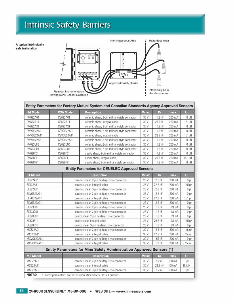
24-HOUR SENSORLINESM 716-684-0003 • WEB SITE — www.imi-sensors.com
Intrinsic Safety BarriersIntrinsic Safety Barriers
86
Entity Parameters for Factory Mutual System and Canadian Standards Agency Approved Sensors
FM Model CSA Model Description Vmax Ci lmax LiFM622A01 CS622A01 ceramic shear, 2-pin military-style connector 30 V 1.2 nF 200 mA 0 µHFM622A11 CS622A11 ceramic shear, integral cable 30 V 26.2 nF 200 mA 151µHFM622A31 CS622A31 ceramic shear, 3-pin military-style connector 30 V 1.2 nF 200 mA 0 µHFMVO622A01 CSVO622A01 ceramic shear, 2-pin military-style connector 30 V 1.2 nF 200 mA 0 µHFMVO622A11 CSVO622A11 ceramic shear, integral cable 30 V 26.2 nF 200 mA 151µHFMVO622A31 CSVO622A31 ceramic shear, 3-pin military-style connector 30 V 1.2 nF 200 mA 0 µHFM623C00 CS623C00 ceramic shear, 2-pin military-style connector 30 V 1.2 nF 200 mA 0 µHFM623C01 CS623C01 ceramic shear, 2-pin military-style connector 30 V 1.2 nF 200 mA 0 µH FM628F01 CS628F01 quartz shear, 2-pin military-style connector 30 V 1.2 nF 200 mA 0 µHFM628F11 CS628F11 quartz shear, integral cable 30 V 26.2 nF 200 mA 151 µHFM628F31 CS628F31 quartz shear, 3-pin military style connector 30 V 1.2 nF 200 mA 0 µH
Entity Parameters for CENELEC Approved Sensors
EX Model Description Vmax Ci lmax LiEX622A01 ceramic shear, 2-pin military-style connector 28 V 2.2 nF 200 mA 0 µHEX622A11 ceramic shear, integral cable 28 V 27.2 nF 200 mA 151µHEX622A31 ceramic shear, 3-pin military-style connector 28 V 2.2 nF 200 mA 0 µHEXVO622A01 ceramic shear, 2-pin military-style connector 28 V 2.2 nF 200 mA 0 µHEXVO622A11 ceramic shear, integral cable 28 V 27.2 nF 200 mA 151 µHEXVO622A31 ceramic shear, 3-pin military-style connector 28 V 2.2 nF 200 mA 0 µHEX623C00 ceramic shear, 2-pin military-style connector 28 V 1.2 nF 93 mA 0 µHEX623C01 ceramic shear, 2-pin military-style connector 28 V 1.2 nF 93 mA 0 µHEX628F01 quartz shear, 2-pin military-style connector 28 V 1.2 nF 93 mA 0 µHEX628F11 quartz shear, integral cable 28 V 26.2 nF 93 mA 151µHEX628F31 quartz shear, 3-pin military-style connector 28 V 1.2 nF 93 mA 0 µHMX622A01 ceramic shear, 2-pin military-style connector 30 V 2.3 nF 200 mA 0 mHMX622A11 ceramic shear, integral cable 30 V 27.3 nF 200 mA 0.15 mHMXVO622A01 ceramic shear, 2-pin military-style connector 30 V 53 nF 200 mA 0 µHMXVO622A11 ceramic shear, integral cable 30 V 78 nF 200 mA 0.15 mH
Entity Parameters for Mine Safety Administration Approved Sensors (1)
MS Model Description Vmax Ci lmax LiMS622A01 ceramic shear, 2-pin military-style connector 30 V 1.2 nF 100 mA 0 µHMS622A11 ceramic shear, integral cable 30 V 26.2 nF 100 mA 151µHMS622A31 ceramic shear, 3-pin military-style connector 30 V 1.2 nF 100 mA 0 µH
NOTES: 1. Entity parameters are based upon Mine Safety Class K criteria.
A typical intrinsicallysafe installation

Signal ConditionersSignal Conditioners
87
PCB 716-684-0001 IMI Sensors Division toll-free 800-959-4464 Fax 716-684-3823 E-mail [email protected] Web site www.imi-sensors.com
4-20 mA vibration transmitters
DIN rail signal conditioners
Alarm modules
Battery-powered signal conditioners
Line-powered signal conditioners
Modular signal conditioners
Multi-channel signal conditioners
Sensor simulators
Vibration meters and monitors
Signal conditioners serve to provide vibration sensor excitationpower and prepare measurement signals for readout, recordingor analysis purposes. Although many vibration data collectorsand FFT analyzers incorporate built-in excitation power forICP® sensors, some data loggers, recorders, and computerbased data acquisition systems will require that a separateexcitation source be used.
IMI offers a full complement of signal conditioning equipmentfor both the laboratory and industrial setting. Included arebattery powered, line powered and multi-channel signal conditioners with a host of features such as gain, filtering,and computer control. In addition, vibration transmittersserve to interface ICP® sensors with process PLC, DCS,SCADA, and alarm systems. Finally, a selection of vibrationmonitors satisfy most basic measurement and displayrequirements.
Model 689B01 Vibration TransmitterInterfaces ICP® sensors with process PLC, DCS, SCADA, and alarm systems.
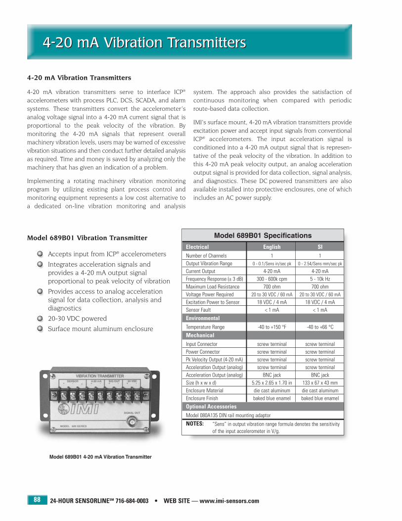
24-HOUR SENSORLINESM 716-684-0003 • WEB SITE — www.imi-sensors.com
4-20 mA Vibration Transmitters4-20 mA Vibration Transmitters
88
4-20 mA vibration transmitters serve to interface ICP®
accelerometers with process PLC, DCS, SCADA, and alarmsystems. These transmitters convert the accelerometer’s analog voltage signal into a 4-20 mA current signal that isproportional to the peak velocity of the vibration. By monitoring the 4-20 mA signals that represent overallmachinery vibration levels, users may be warned of excessivevibration situations and then conduct further detailed analysisas required. Time and money is saved by analyzing only themachinery that has given an indication of a problem.
Implementing a rotating machinery vibration monitoringprogram by utilizing existing plant process control andmonitoring equipment represents a low cost alternative toa dedicated on-line vibration monitoring and analysis
system. The approach also provides the satisfaction of continuous monitoring when compared with periodicroute-based data collection.
IMI’s surface mount, 4-20 mA vibration transmitters provideexcitation power and accept input signals from conventionalICP® accelerometers. The input acceleration signal is conditioned into a 4-20 mA output signal that is represen-tative of the peak velocity of the vibration. In addition tothis 4-20 mA peak velocity output, an analog accelerationoutput signal is provided for data collection, signal analysis,and diagnostics. These DC powered transmitters are alsoavailable installed into protective enclosures, one of whichincludes an AC power supply.
Model 689B01 4-20 mA Vibration Transmitter
Model 689B01 Specifications
Electrical English SINumber of Channels 1 1Output Vibration Range 0 - 0.1/Sens in/sec pk 0 - 2.54/Sens mm/sec pk
Current Output 4-20 mA 4-20 mAFrequency Response (± 3 dB) 300 - 600k cpm 5 - 10k HzMaximum Load Resistance 700 ohm 700 ohmVoltage Power Required 20 to 30 VDC / 60 mA 20 to 30 VDC / 60 mAExcitation Power to Sensor 18 VDC / 4 mA 18 VDC / 4 mASensor Fault < 1 mA < 1 mA
EnvironmentalTemperature Range -40 to +150 °F -40 to +66 °C
MechanicalInput Connector screw terminal screw terminalPower Connector screw terminal screw terminalPk Velocity Output (4-20 mA) screw terminal screw terminalAcceleration Output (analog) screw terminal screw terminalAcceleration Output (analog) BNC jack BNC jackSize (h x w x d) 5.25 x 2.65 x 1.70 in 133 x 67 x 43 mmEnclosure Material die cast aluminum die cast aluminumEnclosure Finish baked blue enamel baked blue enamel
Optional AccessoriesModel 080A135 DIN rail mounting adaptor
NOTES: “Sens” in output vibration range formula denotes the sensitivityof the input accelerometer in V/g.
Model 689B01 Vibration Transmitter
Accepts input from ICP® accelerometers
Integrates acceleration signals and provides a 4-20 mA output signal proportional to peak velocity of vibration
Provides access to analog accelerationsignal for data collection, analysis anddiagnostics
20-30 VDC powered
Surface mount aluminum enclosure
4-20 mA Vibration Transmitters

IMI SENSORS DIVISION TOLL-FREE � 800-959-4464
4-20 mA Vibration Transmitters4-20 mA Vibration Transmitters
89
Series 689B11 Specifications
Available Models1 Channel Enclosure Model 689B11/012 Channel Enclosure Model 689B11/02
Environmental English SIPower Required 20 to 30 VDC / 60 mA 20 to 30 VDC / 60 mATemperature Range -40 to +150 °F -40 to +66 °CEnclosure Rating NEMA 4X IP66
MechanicalSize (h x w x d) 8 x 6 x 4 in 203 x 152 x 102 mmWeight (689B11/01) 2.3 lb 1 kgWeight (689B01/02) 3 lb 1.4 kgEnclosure Material fiberglass fiberglass
Series 689B21 Specifications
Available Models1 Channel Enclosure Model 689B21/012 Channel Enclosure Model 689B21/023 Channel Enclosure Model 689B21/034 Channel Enclosure Model 689B21/045 Channel Enclosure Model 689B21/056 Channel Enclosure Model 689B21/06
Environmental English SIPower Required 105 to 125 VAC 105 to 125 VACTemperature Range -40 to +150 °F -40 to +66 °CEnclosure Rating NEMA 4 IP55
MechanicalSize (h x w x d) 15 x 15 x 8.5 in 381 x 381 x 216 mmWeight 25.9 + (0.67 × channels) lb 11.8 + (0.3 × channels) kg
Enclosure Material painted steel painted steel
Series 689B11 Vibration Transmitter Enclosure
Accommodates up to two Model 689B01transmitters in a fiberglass, NEMA 4Xenclosure
20-30 VDC powered
Series 689B21 Vibration Transmitter Enclosure
Accommodates up to six Model 689B01transmitters in a fiberglass, NEMA 4enclosure
105-125 VAC powered
Model 689B21/064-20 mA Vibration Transmitter Enclosure
Model 689B11/024-20 mA Vibration Transmitter Enclosure

24-HOUR SENSORLINESM 716-684-0003 • WEB SITE — www.imi-sensors.com
Handheld Vibration Meter KitHandheld Vibration Meter Kit
90
Model 687A01 Handheld Vibration Meter Kit
Provides portable velocity and acceleration measurements
Complies with ISO 2954 and ISO10816 standards
Measures the vibration severity offans, motors, and pumps
Verifies bias voltage of industrialaccelerometers for troubleshootingpermanently installed sensors andcables
The Model 687A01 Vibration Meter Kit puts predictivemaintenance into the hands of machinery operators.Simple enough to use with minimal training, it convenientlymeasures the vibration levels of bearings, gears, and spindlesfor predictive maintenance requirements.
The kit is supplied with headphones for audible monitoring,an industrial accelerometer, a cable assembly, and a high-
strength mounting magnet. The portable, lightweight, battery-powered meter provides both overall accelerationand velocity measurements.
Ideal for measuring the vibration severity of fans, motors,and pumps, it also verifies the DC bias voltage of industrialaccelerometers for troubleshooting permanently installedsensors and cables.
Model 687A01 Handheld Vibration Meter Kit
Electrical English SIExcitation Voltage (± 1 VDC) 24 VDC 24 VDC Excitation Current (± 0.6 mA) 2 mA 2 mAFrequency Response:
Velocity (+ 10%, - 20%) 600 - 60,000 cpm 10 - 1000 HzAcceleration (± 3dB) 3,000 - 3,000,000 cpm 50 - 50k Hz
Acceleration Range 0.01 - 19.99 grms metric units unavailableVelocity Range 0.001 - 1.999 in/sec rms metric units unavailableDC Bias Range 0 - 19.99 VDC 0 - 19.99 VDCAccelerometer Sensitivity (± 20%) 100 mV/g 100 mV/gMeter Resolution ± 2 counts ± 2 countsAccuracy ± 3% ± 3%Battery Life (alkaline) 10 hours 10 hoursBattery Life (rechargeable) 3 hours 3 hours
EnvironmentalTemperature Range:
Accelerometer -65 to +250 °F -54 to +121 °CMeter +32 to +122 °F 0 to +50 °C
MechanicalComplete Kit: Size (l x w x h) 15 × 11 × 4.4 in 381 × 279 × 111 mm
Weight 3.90 lb 1.77 kgSensor: Size (hex x height) 7/8 x 1.9 in 7/8 in x 48.3 mm
Weight 2.8 oz 80 gmMounting Thread (female) 1/4-28 UNF 1/4-28 UNF
Meter: Size (l x w x h) 5.9 x 3.15 x 1.2 in 150 x 80 x 30 mmWeight (with battery) 0.57 lb 258 gmInput Connector BNC jack BNC jackHeadphone Connector 1/8" stereo jack 1/8" stereo jack
Supplied ComponentsModel 687A02 MeterModel 601A01 SensorModel 050BQ006AC CableModel 070A47 HeadphonesModel 080A155 Magnet
OptionsModel R687A01 — Rechargeable Version: includes Model 073M12 External Charger
and Model 073A09 Ni-Cad battery replaces alkaline battery.
Model 687A01 Handheld Vibration Meter Kit

IMI SENSORS DIVISION TOLL-FREE � 800-959-4464
Vibration Meters and MonitorsVibration Meters and Monitors
91
True G rms Vibration Monitor
Model 487B07 provides ICP® sensorexcitation and accepts input fromeither a 10 or 100 mV/g accelerometer.Overall vibration levels within a frequency range of 2 to 10k Hz aredisplayed on an analog meter whosefull scale range is adjustable to 1, 4,10, or 40 g rms. High and low setpoints activate rear panel relays toindicate an alarm condition. An analog output for waveformanalysis and a DC output for recording are included. 105 to125 VAC, 50 to 400 Hz powered.
Universal Integrating Vibration Monitor
Model 487A12 provides ICP®
sensor excitation and acceptsinput from any accelerometerhaving a sensitivity between 10and 1000 mV/g. Overall vibrationlevels to 10k Hz are displayed onan LCD meter. Units displayedare selectable among g rms, gpeak, in/sec pk, and mils pk-pk.Additional features include ananalog signal output for waveform analysis, a DC output forrecording, self calibration, auto-ranging, overload indication,and “low range” mode. 105 to 125 VAC, 50 to 60 Hz powered.
Two-Channel Vibration Monitor
Model 487A14 provides ICP® sensor excitation and acceptstwo inputs from either 10 or 100 mV/g accelerometers.Overall vibration levels within a frequency range of 2 to 5600Hz (-3 dB) and amplitudes to 20 g rms are displayed on dualLCD meters in selectable units of g rms or g peak. A high setpoint activates a rear panel relay to alarm of upset conditions.Analog outputs for waveform analysis and a DC output forrecording areincluded foreach channel.120 VAC, 50to 60 Hzpowered.
Portable G rms Vibration Meter
Model 487C08 provides ICP® sensor excitation and acceptsinput from a 100 mV/g accelerometer. Overall vibration levelswithin a frequency range of 5 to 10k Hz aredisplayed on an analog meter whose fullscale range is adjustable to 0.25, 2.5, or 25 g rms. An analog output forwaveform analysis is included. Batterypowered by two standard 9 volt batteries. Ni-cad batteries with recharger option andkit configuration including accelerometerand mounting accessories are also available.
Current Output Vibration Monitor
Model 487A13 provides ICP® sensor excitation and acceptsinput from either a 10 or 100 mV/g accelerometer. Overallvibration levels within a frequency range of 2 to 10k Hz aredisplayed on an analog meter whose full scale range isadjustable to 1, 4, 10, or 40 g rms. A high set point activatesa rear panel relay to indicate analarm condition. A 4 to 20 mAcurrent output proportional to grms adapts to process controlinstrumentation, PLC’s andrecorders. An analog output forwaveform analysis and a DC out-put are included. 105 to 125VAC, 50 to 400 Hz powered.
Vibration and Frequency Monitor
Model 487B10 provides ICP® sensor excitation and acceptsinput from either a 10 or 100 mV/g accelerometer. Overallvibration levels to 40 g and predominant frequency valueswithin a frequency range of 4 to 2000 Hz are displayed onindependent LCD meters. High and low set points activaterear panel relays to alarm of upset conditions. Additional features include alarm LED’s, a 100 Hz engageable low passfilter, an analog output for waveform analysis, and a DC outputfor recording. 115 VAC, 60 Hzpowered.
Model 487B07
Model 487A14
Model 487C08
Model 487B10
Model 487A13
Model 487A12

24-HOUR SENSORLINESM 716-684-0003 • WEB SITE — www.imi-sensors.com
DIN Rail Signal ConditionersDIN Rail Signal Conditioners
92
Model 682A03 - ICP® Sensor to 4-20 mA Transmitter
Provides constant current ICP® sensor excitation
Adjustable low-pass and high-pass filtering
Peak or rms proportional output
Selectable acceleration, velocity, or displacement output signal
24 VDC powered
DIN rail mount
4-20 mA output proportional to temperature “TO” sensor option input
3.9 in (h) × 0.88 in (w) × 4.5 in (d)(99.0 mm × 22.4 mm × 114.5 mm)
Model 682A01 - 24 VDC Power Supply
120 to 230 VAC powered
DIN rail mount
3.75 kV isolation
650 mA maximum
3.9 in (h) × 0.88 in (w) × 4.5 in (d)(99 mm × 22.4 mm × 114.5 mm)
Model 682A02 - ICP® Sensor Signal Conditioner
Provides constant current ICP® sensor excitation
Provides gain ×1, ×10, ×100
24 VDC powered
DIN rail mount
3.3 in (h) × 0.97 in (w) × 3.1 in (d)(83.8 mm × 24.6 mm × 78.7 mm)

IMI SENSORS DIVISION TOLL-FREE � 800-959-4464
Alarm ModulesAlarm Modules
93
Series 683A - Indicator / Alarm
Provides 24 VDC excitation for 4-20 mA sensors
Highly visible, fully scalable LED display
Up to four, programmable, set point relays
Time delay eliminates false alarm trips
1/8 DIN panel mounting
User-friendly, menu-driven, set up
1.89 in (h) × 3.93 in (w) × 5.27 in (d)(48 mm × 99.9 mm × 134.1 mm)
Model 682A04 - Relay Alarm Module
Accepts 4-20 mA signal input
Provides two, 5 A, Form C alarm relayswith selectable 30 second time delay
DIN rail mount
3.9 in (h) × 0.88 in (w) × 4.5 in (d)(99 mm × 22.4 mm × 114.5 mm)
BBaassee MMooddeell
683A Indicator / alarm with two, time-delayed, Form A, set-point relays
IInnppuutt
0 4-20 mA DC with 24 VDC excitation delivered to sensor / transmitter
PPoowweerr RReeqquuiirreedd
0 85 to 265 VAC or 95 to 370 VDC1 18 to 48 VAC or 10 to 72 VDC
AAnnaalloogg OOuuttppuutt
0 None1 Isolated 16 bit user scalable 4-20 mA retransmit
AAddddiittiioonnaall RReellaayy OOuuttppuuttss
0 None1 Dual 10 Amp Form C relays (not time-delayed)2 Dual 5 Amp Form A relays (not time-delayed)
AAcccceessssoorriieess
00 None01 NEMA 4X, clear, lockable, splash-proof front cover02 Metal surround case - includes screw mounting clips03 NEMA 4X, clear front cover and metal surround case
EExxaammppllee683A 0 0 0 0 01 Standard indicator / alarm with NEMA 4X front cover

24-HOUR SENSORLINESM 716-684-0003 • WEB SITE — www.imi-sensors.com
Battery-Powered Signal Conditionersfor ICP® SensorsBattery-Powered Signal Conditionersfor ICP® Sensors
94
Battery-Powered Signal ConditionersMODEL NUMBERS 480C02 480E09 480B10 480B21Style basic gain integrating triaxial
accel, vel., displ. with gainChannels 1 channel 1 channel 1 channel 3 channelsSensor Excitation 27 volt, 2 mA 27 volt, 2 mA 18 volt, 2 mA 25-30 volt, 3 mAGain unity x1, x10, x100 unity x1, x10, x100Low Frequency Response (- 5%) (1) 0.05 Hz 0.15 Hz 0.07 (a), 8 (v), 15 (d) 0.15 HzHigh Frequency Response (- 5%) 500 000 Hz 100 000 Hz 100 (a), 10(v), 1 (d) kHz 90 000 HzBroadband Noise (at unity gain) 360 nV rms 360 nV rms N/A 3.54 µV rmsBattery (qty) Type (3) 9 V (3) 9 V (2) 9 V (3) 9 VAverage Battery Life 100 hour 40 hour 30 hour 32 hourInput/Output Connectors BNC/BNC BNC/BNC BNC/BNC BNC or 4-pin/BNCExternal DC Powerable yes yes no yesDC Power Input Jack 1/8 dia. 1/8 dia. — mini DIN 6-pin jackSize (h x w x d) 4.0 x 2.9 x 1.5 in 4.0 x 2.9 x 1.5 in 4.0 x 2.9 x 1.5 in 7.5 x 5 x 2 in
(102 x 74 x 38 mm) (102 x 74 x 28 mm) (102 x 74 x 28 mm) (191 x 127 x 51 mm)Weight 0.62 lb (284 g) 0.75 lb (341 g) 0.61 lb (277 g) 1.1 lb (499 g)
Optional Models10-32 Input/Output Connectors 480C 480E06 N/A N/ARechargeable R480C02 R480E09 R480B10 N/A
(supplied with Ni-Cad batteriesand AC powered recharger unit)
OptionsAC Powered Recharger Unit with 488A02 488A02 488A02 N/A(3) 9 V Ni-Cad BatteriesAC Power Supply 488A03 488A03 — 488A10Ultralife Lithium Batteries (3) > 200 hours operation — > 100 hours operation
NOTES: 1. Achieved with readout device having a 1 megohm input impedance.
Model 480C02Unity gain, low noise,
high frequency
Model 480E09Gain x1, x10, x100
Model 480B10Integrating: acceleration,
velocity, displacement
Model 480B213 channel, triaxial, gain x1, x10, x100
Battery-powered signal conditioners offer portable, convenientmethods for powering ICP® sensors and conditioning their outputsignals for transmittal to readout and recording instruments.Most units operate, and are supplied, with standard 9 voltalkaline batteries. Each features a color-coded, input circuit
checkout meter to alert of proper sensor turn-on or input faultdue to open or short circuit connectors. Rechargeable versions are equipped with Ni-Cad batteries and supplied withan AC powered recharger unit.
Battery-Powered, ICP® Sensor Signal Conditioners
Model 488A03AC power supply
Model 488A02Battery charger

IMI SENSORS DIVISION TOLL-FREE � 800-959-4464
Line-Powered Signal Conditionersfor ICP® Sensors
Line-Powered Signal Conditionersfor ICP® Sensors
95
Line-Powered Signal ConditionersMODEL NUMBERS 482A21 482A22 482B06 482B11 484B06 484B11Style low noise low noise basic gain low frequency low frequency
AC and DC power AC and DC power AC/DC coupled with gainChannels 1 channel 4 channels 1 channel 1 channel 1 channel 1 channelSensor Excitation (1) 26 volt, 2 to 20 mA 26 volt, 2 to 20 mA 24 volt, 2 to 20 mA 24 volt, 2 to 20 mA 24 volt, 2 to 20 mA 24 volt, 2 to 20 mAGain unity unity unity x1, x10, x100 unity x1, x10, x100Low Frequency Response (- 5%) < 0.1 Hz (2) < 0.1 Hz (2) < 0.05 Hz 0.17 Hz DC DCHigh Frequency Response (- 5%) > 1 000 000 Hz > 1 000 000 Hz 1 000 000 Hz 200 000 Hz 200 000 Hz 200 000 HzBroadband Noise (at unity gain) < 3.25 µV rms < 3.25 µV rms < 3.64 µV rms N/A 28.8 µV rms 10 µV rmsPower Required 36 VDC 36VDC 115 VAC 115 VAC 115 VAC 115 VAC
120 mA (3) 120 mA (3) 50 to 400 Hz 50 to 400 Hz 50 to 400 Hz 50 to 400 HzInput/Output Connectors BNC/BNC BNC/BNC BNC/BNC BNC/BNC BNC/BNC BNC/BNCExternal DC Powerable yes yes no no no noDC Power Input Jack DIN DIN — — — —Size (h x w x d) 6.3 x 2.4 x 11 in 6.3 x 2.4 x 11 in 4.3 x 1.8 x 6 in 4.3 x 1.8 x 6 in 4.3 x 1.8 x 6 in 4.3 x 1.8 x 6 in
(106 x 61 x 279 mm) (106 x 61 x 279 mm) (109 x 46 x 152 mm) (109 x 46 x 152 mm) (109 x 46 x 152 mm) (109 x 46 x 152 mm)Weight 1.51 lb (685 gm) 1.67 lb (756 gm) 1.2 lb (544 gm) 2 lb (907 gm) 2 lb (907 gm) 2 lb (907 gm)
Optional Models10-32 Input/Output Connectors N/A N/A N/A N/A 484B 484B10210 to 250 VAC Powerable standard standard F482B06 F482B11 F484B06 F484B11
OptionsExternal 36 VDC Battery Pack 488A07 488A07 N/A N/A N/A N/A
NOTES: 1. Current is factory set at 4 mA but is user adjustable between 2 and 20 mA.2. Achieved with readout device having a 1 megohm input impedance.3. Supplied with Model 488A04 AC power adaptor (100 to 240 VAC, 50 to 60 Hz input; 36 VDC 120 mA output).
Model 482A21Unity gain, low noise,AC and DC powerable
Model 482A224 channel, unity gain, lownoise, AC and DC power-
able
Model 482B06Basic, unity gain
Model 482B11Gain x1, x10, x100
Line-powered signal conditioners offer benchtop methods forpowering ICP® sensors in the laboratory and conditioning theiroutput signals for transmittal to readout and recording instru-ments. Each features a color-coded, input circuit checkoutmeter to alert of proper sensor turn-on or input fault due toopen or short circuit connections. AC and DC powerable units
can operate either with the supplied AC powered transformeror optional external battery pack. AC/DC coupled outputsoffer the ability to achieve true DC frequency response inorder to accurately condition very low frequency vibrations orlong duration shock pulses.
Line-Powered, ICP® Sensor Signal Conditioners
Model 484B06Low frequency, unity gain,
AC/DC coupled output
Model 484B11Low frequency, gain x1, x10, x100,
AC/DC coupled output

24-HOUR SENSORLINESM 716-684-0003 • WEB SITE — www.imi-sensors.com
Line-Powered Signal Conditionersfor ICP® SensorsLine-Powered Signal Conditionersfor ICP® Sensors
96
Model 482A164 channel,
gain x1, x10, x100
Model 482A188 channel
gain x1, x10, x1008 to 1 output
switching
Full-Featured, Line-Powered Signal Conditioners with GainMODEL NUMBERS 482A16 482A20Style full feature with gain full feature with gainChannels 4 channels 8 channelsSensor Excitation (1) 24 volt, 2 to 20 mA 24 volt, 2 to 20 mAGain (each channel) x1, x10, x100 x1, x10, x100Low Frequency Response (- 5%) 0.225 Hz (2) 0.225 Hz (2)High Frequency Response (- 5%) 100 000 Hz 100 000 HzBroadband Noise (at unity gain) 9.1 µV rms 9.1 µV rmsPower Required 90 to 130 VAC 90 to 130 VAC
50 to 400 Hz 50 to 400 HzInput/Output Connectors BNC/BNC BNC/BNCSize (h x w x d) 6.3 x 2.9 x 9.7 in 6.3 x 4.0 x 9.7 in
(160 x 74 x 246 mm) (160 x 102 x 246 mm)Weight 2 lb (907 gm) 6.1 lb (2769 gm)
Optional Models4 to 1 Output Switching 482A17 482A19 (3)8 to 1 Output Switching N/A 482A18210 to 250 VAC Powerable F482A16 F482A20
NOTES: 1. Current is factory set at 4 mA but is user adjustable between 2 and 20 mA.2. Achieved with readout device having a 1 megohm input impedance.3. Model 482A19 offers dual 4 to 1 output switching and is ideally suited for use with two
channel analyzers.
These full-featured, multi-channel, line-powered signal condi-tioners offer push-button, selectable gain for each channeland optional output switching to simplify data acquisition.Each features a bank of LED’s on each channel to indicategain setting, input overload, and input fault due to open or
short circuit connections. In addition to the channel specificBNC’s, the optional switched output units offer additionaloutput BNC’s that carry the signals of the switch-selectedchannel.
Multi-Channel, Line-powered ICP® Sensor Signal Conditioners with Gain
Preconfigured Modular Style Signal ConditionersSignal Conditioning Accessories
ICP® Sensor Simulator
Model 492B
Model 492B ICP® sensor simulator installsin place of an ICP® sensor and serves to verifysignal conditioning settings, cable integrity,and tune long lines for optimum system performance. By use of an internal oscillator,the unit delivers a 100 Hz sine or squarewave at a selectable peak to peak voltage.External test signals from a function generatormay also be inserted. This portable unit isbattery powered.
ICP® Sensor Simulator
Model 401A04
Model 401A04 ICP® sensor simulatorinstalls in place of an ICP® sensor andaccepts test signals from a voltagefunction generator. The unit serves toverify signal conditioning settings,cable integrity, and tune long lines foroptimum system performance. Thisunit requires power from an ICP® sensorsignal conditioner.
DC Power Conditioner
Model 485B
Model 485B serves to regulate availablecurrent from any conventional 18 to 28VDC power supply or battery source to aconstant value between 2 and 20 mA asrequired by ICP® sensors. In addition, theunit decouples the sensor’s output biasvoltage from the measurement signal toenable zero based measurements withany readout device.

IMI SENSORS DIVISION TOLL-FREE � 800-959-4464
Modular Style Signal ConditionersModular Style Signal Conditioners
97
Modular Style Signal Conditioners
Modular signal conditioners are comprised of selected signal conditioning modules, and an AC power supply module, assembledinto a 2-, 3-, 5- or 9-slot chassis. Available modules conditionICP®, charge, or capacitive sensor signals. The common chassis backplane architecture permits mixing and matching of modulesto achieve the desired number of channels and signal conditioningfeatures. Preconfigured models offer ease of ordering units possessing the most commonly requested features. Request the“Series 440 Modular Signal Conditioners” brochure for full detailsof available items.
Modular Signal Conditioner
Systems
Modular Style Signal ConditionersMODEL NUMBERS 442B02 442C04 442B06 443B01Style ICP sensor with gain ICP sensor with gain ICP sensor AC/DC coupling charge, ICP, and TEDSChannels 1 channel 4 channels 1 channel 1 channelSensor Excitation (1) 24 volt, 1 to 20 mA 25.5 volt, 0.5 to 20 mA 24 volt, 1 to 20 mA 24 volt, 2 to 20 mA (2)Gain (each channel) x1, x10, x100 x1, x10, x100 x1, x10, x100 0.1 to 1000Charge Sensitivity N/A N/A N/A 0.0001 to 10 volts/pCLow Frequency Response 0.05 Hz (- 5%) (3) 0.05 Hz (- 5%) (3) DC 0.2/2 Hz (- 10%) (4)High Frequency Response 100k Hz (- 5%) 100k Hz (- 5%) 100k Hz (- 5%) 100, 1k, 3k, 10k, 110k Hz (- 10%) (5)Broadband Noise (at unity gain) 8.3 µV rms 10 µV rms 12.5 µV rms 9 µV rmsPower Required 100 to 240 VAC 100 to 240 VAC 100 to 240 VAC 100 to 240 VAC
50 to 60 Hz 50 to 60 Hz 50 to 60 Hz 50 to 60 HzInput/Output Connectors BNC/BNC BNC/BNC BNC/BNC BNC/BNCSize (h x w x d) 6.2 x 4.25 x 10.2 in 6.2 x 4.25 x 10.2 in 6.2 x 4.25 x 10.2 in 6.2 x 6.05 x 10.2 in
(158 x 108 x 259 mm) (158 x 108 x 259 mm) (158 x 108 x 259 mm) (158 x 108 x 259 mm)Weight 4.9 lb (2.2 kg) 5.1 lb (2.3 kg) 5.0 lb (2.3 kg) 6.55 lb (2.97 kg)
NOTES: 1. Current is factory set at 4 mA but is user adjustable up to 20 mA.2. Excitation is disabled for charge mode sensor input.3. Achieved with readout device having a 1 megohm input impedance.4. Adjusted by Discharge Time Constant selection.5. Adjusted by Low Pass Filter selection.
Model 442B02Single channel,
gain x1, x10, x100for ICP® sensors
Model 442C044 channel, gain x1, x10, x100
for ICP® sensors
Model 442B06Single channel, gain x1, x10, x100
AC and DC coupling for ICP® sensors
Model 443B01Dual-Mode Vibration Amplifier
for charge, TEDS, and ICP® sensors
Preconfigured Modular Style Signal ConditionersPreconfigured Modular Style Signal Conditioners

24-HOUR SENSORLINESM 716-684-0003 • WEB SITE — www.imi-sensors.com
Multi-Channel Signal ConditionersMulti-Channel Signal Conditioners
98
Multi-channel, rack-mount, signal conditioners contain 16channels of simultaneous signal conditioning and can be configured for multiple unit, daisy-linking with computerizedset-up and control. The building-block style architecture per-mits factory configuration to include characteristics which besttailor a unit for the specific application and data acquisitionrequirements. Standard features include ICP® sensor excitationand LED indicators for input fault monitoring and overloaddetection. Optional features include programmable gain,
autoranging, filtering, output switching, integration, IEEE-488,RS-232, and RS-485 interface, and keypad control with LCD display. Units are available to condition signals from ICP sensors, charge-mode sensors, or can be set up to accept voltage input signals from other types of sensors. Preconfiguredmodels offer ease of ordering units possessing the most commonly requested features. Request the “Series 481Multi-Channel Signal Conditioners” brochure for full details ofavailable items.
Multi-Channel Signal Conditioners
Multi-Channel Signal ConditionersMODEL NUMBERS 481A01 481A02 481A03Style unity gain selectable gain continuous gain adjust
with keypad & display with keypad & displayChannels 16 channels 16 channels 16 channelsSensor Excitation (1) 24 volt, 3 to 20 mA 24 volt, 3 to 20 mA 24 volt, 3 to 20 mAGain (each channel) unity autoranging continuous
x1, x10, x100 x0.1 to x200Frequency Response (± 5%) 0.5 to 100 000 Hz 0.5 to 100 000 Hz 0.5 to 90 000 Hz (2)Broadband Noise (at unity gain) 11 µV rms 11 µV rms 4 mVPower Required 100 to 240 VAC 100 to 240 VAC 100 to 240 VAC
47 to 63 Hz 47 to 63 Hz 47 to 63 HzKeypad Control no yes yesComputer Control no RS-232 and RS-485 RS-232 and RS-485Input Connectors DB50 and BNC DB50 and BNC DB50 and BNCOutput Connectors DB37 and BNC DB37 and BNC DB37 and BNCSize (h x w x d) 3.5 x 19.0 x 16.25 in 3.5 x 19.0 x 16.25 in 3.5 x 19.0 x 16.25 in
(89 x 483 x 413 mm) (89 x 483 x 413 mm) (89 x 483 x 413 mm)Weight 15 lb (6.8 kg) 15 lb (6.8 kg) 15 lb (6.8 kg)
NOTE: 1. Current is factory set at 4 mA but is user adjustable between 3 and 20 mA.2. Attains 90 000 Hz with filter disabled.
Model 481A0216 channel,
gain x1, x10, x100for ICP® sensors
Model 481A0316 channel,
continuous gain x0.1 to x200for ICP® sensors
Model 481A0116 channel, unity gain
for ICP® sensors
Preconfigured Multi-channel Signal ConditionersPreconfigured Multi-channel Signal Conditioners

99
PCB 716-684-0001 IMI Sensors Division toll-free 800-959-4464 Fax 716-684-3823 E-mail [email protected] Web site www.imi-sensors.com
Accessory EquipmentAccessory Equipment
Cable assemblies
Cable connectors
Magnetic bases
Mounting hardware
Installation tools
Portable shakers
IMI manufactures a multitude of accessory equipment tocomplement the use and installation of industrial vibrationsensors. Many of the cables and mounting accessories arecompatible not only with IMI’s sensors, but also sensors anddata collection devices from other manufacturers. Most accessory equipment is stocked to accommodateemergency needs.
It is important to recognize that cables are vulnerable todamage and should be installed out of harms way. Armoredcables offer further protection from flying, machined chips,debris, or when cables may be located under foot. Havingspare cables on hand is recommended as they can help trou-bleshoot system performance and keep a measurement sys-tem up and running in the event of a cable failure.
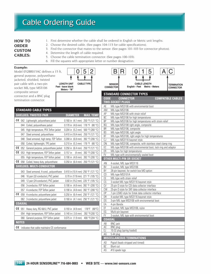
24-HOUR SENSORLINESM 716-684-0003 • WEB SITE — www.imi-sensors.com
Cable Ordering GuideCable Ordering Guide
100
1. First determine whether the cable shall be ordered in English or Metric unit lengths. 2. Choose the desired cable. (See pages 104-113 for cable specifications).3. Find the connector that mates to the sensor. (See pages 101-103 for connector photos).4. Determine the length of cable required.5. Choose the cable termination connector. (See pages 100-103). 6. Fill the squares with appropriate letter or number designation:
Example:Model 052BR015AC defines a 15 ft, general purpose, polyurethane jacketed, shielded, twisted pair cable with a two-pin socket MIL type MS3106 composite sensor connector and a BNC plug termination connector.
0 5 2 B R 0 1 5 A C
LENGTH UNITFeet - leave blank
Meters - “M”
CABLE LENGTHEnglish - Feet Metric - Meters
CABLE TYPE SENSORCONNECTOR
TERMINATIONCONNECTOR
STANDARD CONNECTOR TYPESCODE CONNECTOR COMPATIBLE CABLESTWO-SOCKET PLUGSAE MIL-type MS3106 with environmental bootAM MIL-type MS3106AP MIL-type MS3106 with strain reliefBC MIL-type MS3106 for high temperaturesBP MIL-type MS3106 for high temperatures with strain reliefBQ MIL-type MS3108 right angle, compositeBR MIL-type MS3106, compositeBS MIL-type MS3108, right angleBT MIL-type MS3108, right angle for high temperaturesCJ MIL-type MS3116 bayonet styleDN MIL-type MS3106, composite, with stainless steel clamp ringEC MIL-type MS3106 with environmental boot, lock ring and adaptorER MIL-type for high temperaturesFV MIL-type with environmentally sealed bootOTHER MULTI-PIN OR SOCKETAN 4-socket, MIL type MS3116BV 3-socket, MIL type MS3106BY 28-pin bayonet, for switch box MO optionCD MIL-type MS3101ACE MIL-type with strain reliefCS 3-socket MIL type MS3116 bayonet styleCV 25-pin D style for CSI data collector interfaceCW 25-pin D style for SKF data collector interfaceDP 7-pin LEMO style for Entek data collector interfaceDR 4-socket MIL type MS3116 bayonet styleDS 3-pin MIL type MS3106 with environmental bootEA 4-pin BendixEF 3-socket, MIL type MS3106, nylonEG Multi-pin bayonetFY 3-socket, MIL type with environmental bootCOAXIALAB BNC jackAC BNC plugEJ 10-32 plug (spring loaded)AG 5-44 plugMISCELLANEOUS TERMINATIONSAD Pigtail (leads stripped and tinned)BZ Blunt cutAS #10 spade lugs
STANDARD CABLE TYPESSHIELDED, TWISTED PAIR DIAMETER MAX. TEMP.
042 Lightweight, polyurethane jacket 0.160 in (4.1 mm) 250 °F (121 °C)044 Coiled, polyurethane jacket 0.170 in (4.6 mm) 176 °F (80 °C)045 High temperature, PFA Teflon jacket 0.204 in (5.2 mm) 500 °F (260 °C)047 Steel armored, polyurethane 0.410 in (10.4 mm) 250 °F (121 °C)048 Steel armored, high temp. FEP Teflon 0.268 in (6.8 mm) 392 °F (200 °C)050 Coiled, lightweight, TPE jacket 0.210 in (5.3 mm) 176 °F (80 °C)052 General purpose, polyurethane jacket 0.250 in (6.4 mm) 250 °F (121 °C)053 High temperature, FEP Teflon jacket 0.157 in (4 mm) 392 °F (200 °C)055 High temperature, FEP Teflon jacket 0.190 in (4.8 mm) 392 °F (200 °C)058 Coiled, heavy duty, polyurethane 0.250 in (6.4 mm) 250 °F (121 °C)
SHIELDED, MULTI-CONDUCTOR
043 Steel armored, 4-cond., polyurethane 0.410 in (10.4 mm) 250 °F (121 °C)046 16 pair (32-conductor), PVC jacket 0.70 in (17.8 mm) 221 °F (105 °C)049 12 pair (24-conductor), PVC jacket 0.60 in (15.2 mm) 220 °F (105 °C)056 3-conductor, FEP Teflon jacket 0.190 in (4.8 mm) 392 °F (200 °C)057 4-conductor, FEP Teflon jacket 0.190 in (4.8 mm) 392 °F (200 °C)059 4-conductor, polyurethane jacket 0.250 in (6.4 mm) 250 °F (121 °C)062 3-conductor, polyurethane jacket 0.160 in (4.1 mm) 250 °F (121 °C)
COAXIAL
051 Heavy duty, RG-58/U, PVC jacket 0.193 in (4.9 mm) 176°F (80°C)054 High temperature, FEP Teflon jacket 0.140 in ( 3.6 mm) 392 °F (200 °C)060 General purpose, FEP Teflon jacket 0.075 in (1.9 mm) 400 °F (204 °C)
NOTES
indicates that cable maintains CE conformance
HOW TOORDERCUSTOMCABLES:
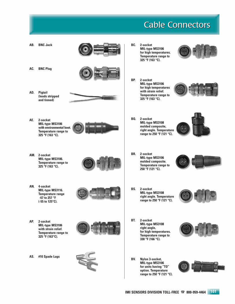
IMI SENSORS DIVISION TOLL-FREE � 800-959-4464
Cable ConnectorsCable Connectors
101
AB. BNC Jack
AC. BNC Plug
AD. Pigtail (leads stripped and tinned)
AE. 2-socket MIL-type MS3106 with environmental boot.Temperature range to 325 °F (163 °C).
AM. 2-socketMIL-type MS3106.Temperature range to 325 °F (163 °C).
AN. 4-socket MIL-type MS3116.Temperature range-67 to 257 °F
(-55 to 125°C).
AP. 2-socketMIL-type MS3106with strain relief.Temperature range to 325 °F (163°C).
AS. #10 Spade Lugs
BC. 2-socketMIL-type MS3106for high temperatures.Temperature range to 325 °F (163 °C).
BP. 2-socketMIL-type MS3106for high temperatureswith strain relief.Temperature range to 325 °F (163 °C).
BQ. 2-socketMIL-type MS3108molded composite, right angle. Temperaturerange to 250 °F (121 °C).
BR. 2-socketMIL-type MS3106molded composite.Temperature range to 250 °F (121 °C).
BS. 2-socketMIL-type MS3108right angle. Temperaturerange to 250 °F (121 °C).
BT. 2-socketMIL-type MS3108right angle,for high temperatures.Temperature range to 330 °F (166 °C).
BV. Nylon 3-socket, MIL-type MS3106 for units having “TO”option. Temperaturerange to 250 °F (121 °C).
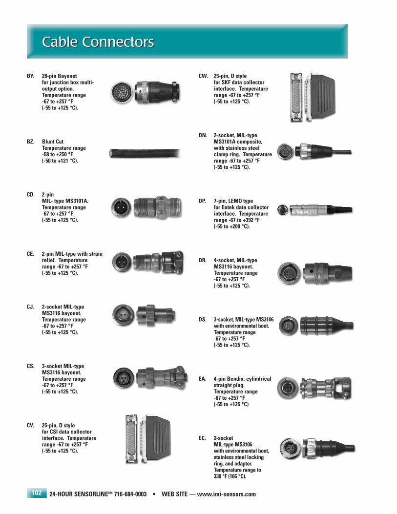
24-HOUR SENSORLINESM 716-684-0003 • WEB SITE — www.imi-sensors.com
Cable ConnectorsCable Connectors
102
BY. 28-pin Bayonetfor junction box multi-output option.Temperature range-67 to +257 °F(-55 to +125 °C).
BZ. Blunt CutTemperature range-58 to +250 °F(-50 to +121 °C).
CD. 2-pinMIL- type MS3101A.Temperature range-67 to +257 °F(-55 to +125 °C).
CE. 2-pin MIL-type with strainrelief. Temperaturerange -67 to +257 °F(-55 to +125 °C).
CJ. 2-socket MIL-type MS3116 bayonet. Temperature range-67 to +257 °F(-55 to +125 °C).
CS. 3-socket MIL-type MS3116 bayonet.Temperature range-67 to +257 °F(-55 to +125 °C).
CV. 25-pin, D stylefor CSI data collectorinterface. Temperaturerange -67 to +257 °F(-55 to +125 °C).
CW. 25-pin, D stylefor SKF data collectorinterface. Temperaturerange -67 to +257 °F(-55 to +125 °C).
DN. 2-socket, MIL-typeMS3101A composite,with stainless steelclamp ring. Temperaturerange -67 to +257 °F(-55 to +125 °C).
DP. 7-pin, LEMO typefor Entek data collectorinterface. Temperaturerange -67 to +392 °F(-55 to +200 °C).
DR. 4-socket, MIL-type MS3116 bayonet.Temperature range-67 to +257 °F(-55 to +125 °C).
DS. 3-socket, MIL-type MS3106with environmental boot.Temperature range-67 to +257 °F(-55 to +125 °C).
EA. 4-pin Bendix, cylindrical straight plug. Temperature range-67 to +257 °F(-55 to +125 °C)
EC. 2-socketMIL-type MS3106with environmental boot,stainless steel locking ring, and adaptor.Temperature range to 330 °F (166 °C).

EF. Nylon 3-socketMIL-type 3106 for biaxial sensors only.Temperature range to 250 °F (121 °C).
EG. 35-pin bayonet withstrain relief for multipleoutputs. Temperaturerange -67 to +257 °F(-55 to +125 °C).
EJ. 10-32 coaxialspring loaded.Temperature rangeto 392 °F (200 °C).
ER. 2-socket, MIL-typefor high temperatures.Temperature range to 500 °F (260 °C).
FV. 2-socket, MIL-type MS3106 with environmental boot.Temperature range-67 to +257 °F(-55 to +125 °C).
FY. 3-socketMIL-type MS3106 with environmental boot.Temperature range
IMI SENSORS DIVISION TOLL-FREE � 800-959-4464
Cable ConnectorsCable Connectors
103
Field Installable Connector Kits
These connector kits permit users to fabricate their own cable assemblies or conduct cable repairs in the field. It is oftendesirable to install and cut cables to required lengths and then install the necessary sensor connectors.
CF. 2-socket, compositeMIL-type MS3106field installable kit.Temperature range-67 to +257 °F(-55 to +125 °C).
075A01.2-socket, MIL-type MS3106 with environmental bootfor 0.195 in dia. cable.
075A02.2-socket, MIL-type MS3106 with environmental bootfor 0.250 in dia. cable.
075A03.2-socket, MIL-type MS3106 with environmental bootfor 0.170 in dia. cable.
075A04.2-socket, MIL-type MS3106with environmental bootfor 0.140 in dia. cable.
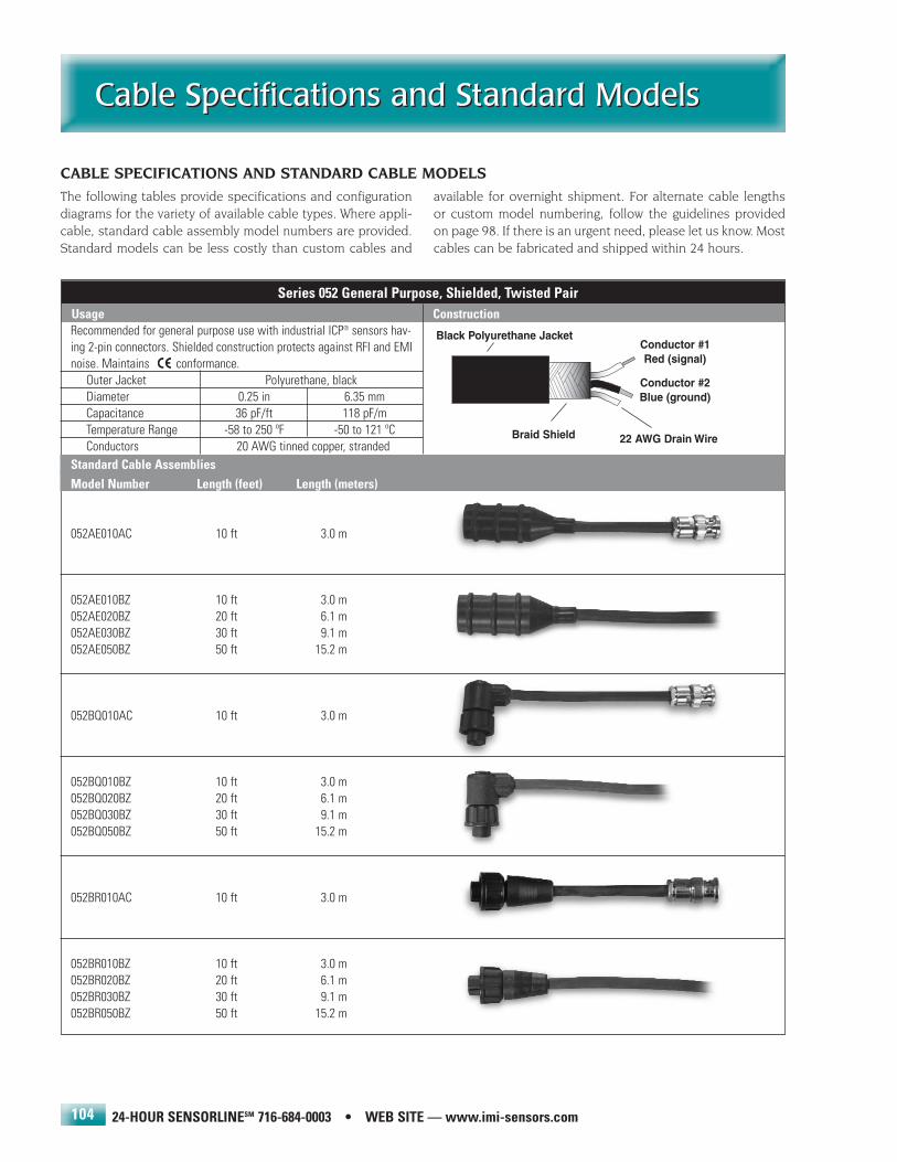
Series 052 General Purpose, Shielded, Twisted PairUsage Construction
24-HOUR SENSORLINESM 716-684-0003 • WEB SITE — www.imi-sensors.com
Cable Specifications and Standard ModelsCable Specifications and Standard Models
104
The following tables provide specifications and configurationdiagrams for the variety of available cable types. Where appli-cable, standard cable assembly model numbers are provided.Standard models can be less costly than custom cables and
available for overnight shipment. For alternate cable lengthsor custom model numbering, follow the guidelines providedon page 98. If there is an urgent need, please let us know. Mostcables can be fabricated and shipped within 24 hours.
CABLE SPECIFICATIONS AND STANDARD CABLE MODELS
Recommended for general purpose use with industrial ICP® sensors hav-ing 2-pin connectors. Shielded construction protects against RFI and EMInoise. Maintains conformance. .
Outer Jacket Polyurethane, blackDiameter 0.25 in 6.35 mmCapacitance 36 pF/ft 118 pF/mTemperature Range -58 to 250 ºF -50 to 121 ºCConductors 20 AWG tinned copper, stranded
Conductor #1Red (signal)
Conductor #2Blue (ground)
22 AWG Drain WireBraid Shield
Black Polyurethane Jacket
Standard Cable AssembliesModel Number Length (feet) Length (meters)
052AE010AC 10 ft 3.0 m
052AE010BZ 10 ft 3.0 m052AE020BZ 20 ft 6.1 m052AE030BZ 30 ft 9.1 m052AE050BZ 50 ft 15.2 m
052BQ010AC 10 ft 3.0 m
052BQ010BZ 10 ft 3.0 m052BQ020BZ 20 ft 6.1 m052BQ030BZ 30 ft 9.1 m052BQ050BZ 50 ft 15.2 m
052BR010AC 10 ft 3.0 m
052BR010BZ 10 ft 3.0 m052BR020BZ 20 ft 6.1 m052BR030BZ 30 ft 9.1 m052BR050BZ 50 ft 15.2 m
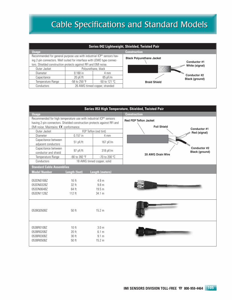
IMI SENSORS DIVISION TOLL-FREE � 800-959-4464
Cable Specifications and Standard ModelsCable Specifications and Standard Models
105
Conductor #1White (signal)
Conductor #2Black (ground)
Braid Shield
Black Polyurethane Jacket
Recommended for high temperature use with industrial ICP® sensorshaving 2-pin connectors. Shielded construction protects against RFI andEMI noise. Maintains conformance. .
Outer Jacket FEP Teflon (red tint)Diameter 0.157 in 4 mmCapacitance between adjacent conductors
51 pF/ft 167 pF/m
Capacitance betweenconductor and shield
97 pF/ft 318 pF/m
Temperature Range -90 to 392 ºF -70 to 200 ºCConductors 18 AWG tinned copper, solid
Standard Cable AssembliesModel Number Length (feet) Length (meters)
053DN016BZ 16 ft 4.9 m053DN032BZ 32 ft 9.8 m053DN064BZ 64 ft 19.5 m053DN112BZ 112 ft 34.1 m
053BQ050BZ 50 ft 15.2 m
053BR010BZ 10 ft 3.0 m053BR020BZ 20 ft 6.1 m053BR030BZ 30 ft 9.1 m053BR050BZ 50 ft 15.2 m
Series 053 High Temperature, Shielded, Twisted PairUsage Construction
Recommended for general purpose use with industrial ICP® sensors hav-ing 2-pin connectors. Well suited for interface with LEMO type connec-tors. Shielded construction protects against RFI and EMI noise.
Outer Jacket Polyurethane, blackDiameter 0.160 in 4 mmCapacitance 20 pF/ft 65 pF/mTemperature Range -58 to 250 ºF -50 to 121 ºCConductors 26 AWG tinned copper, stranded
Conductor #1Red (signal)
Conductor #2Black (ground)
Foil Shield
20 AWG Drain Wire
Red FEP Teflon Jacket
Series 042 Lightweight, Shielded, Twisted PairUsage Construction
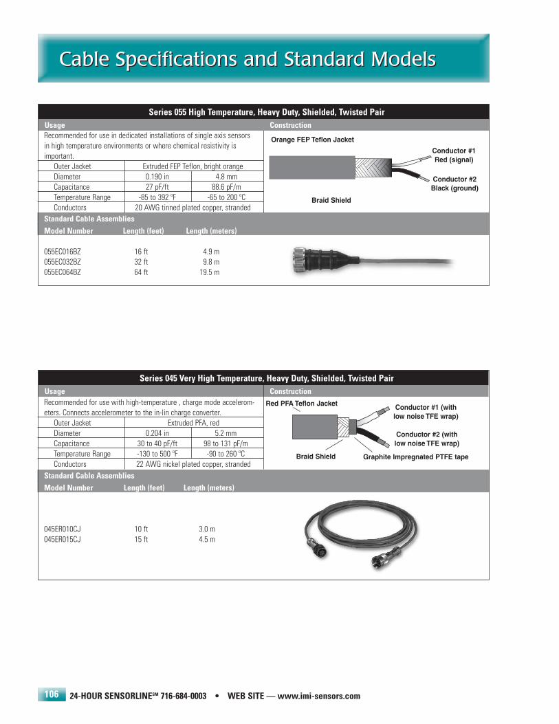
24-HOUR SENSORLINESM 716-684-0003 • WEB SITE — www.imi-sensors.com
Cable Specifications and Standard ModelsCable Specifications and Standard Models
106
Recommended for use with high-temperature , charge mode accelerom-eters. Connects accelerometer to the in-lin charge converter. .
Outer Jacket Extruded PFA, redDiameter 0.204 in 5.2 mmCapacitance 30 to 40 pF/ft 98 to 131 pF/mTemperature Range -130 to 500 ºF -90 to 260 ºCConductors 22 AWG nickel plated copper, stranded
Standard Cable AssembliesModel Number Length (feet) Length (meters)
045ER010CJ 10 ft 3.0 m045ER015CJ 15 ft 4.5 m
Series 045 Very High Temperature, Heavy Duty, Shielded, Twisted PairUsage Construction
Conductor #1 (withlow noise TFE wrap)
Conductor #2 (withlow noise TFE wrap)
Braid Shield
Red PFA Teflon Jacket
Graphite Impregnated PTFE tape
Recommended for use in dedicated installations of single axis sensorsin high temperature environments or where chemical resistivity isimportant. .
Outer Jacket Extruded FEP Teflon, bright orangeDiameter 0.190 in 4.8 mmCapacitance 27 pF/ft 88.6 pF/mTemperature Range -85 to 392 ºF -65 to 200 ºCConductors 20 AWG tinned plated copper, stranded
Standard Cable AssembliesModel Number Length (feet) Length (meters)
055EC016BZ 16 ft 4.9 m055EC032BZ 32 ft 9.8 m055EC064BZ 64 ft 19.5 m
Conductor #1Red (signal)
Conductor #2Black (ground)
Braid Shield
Orange FEP Teflon Jacket
Series 055 High Temperature, Heavy Duty, Shielded, Twisted PairUsage Construction
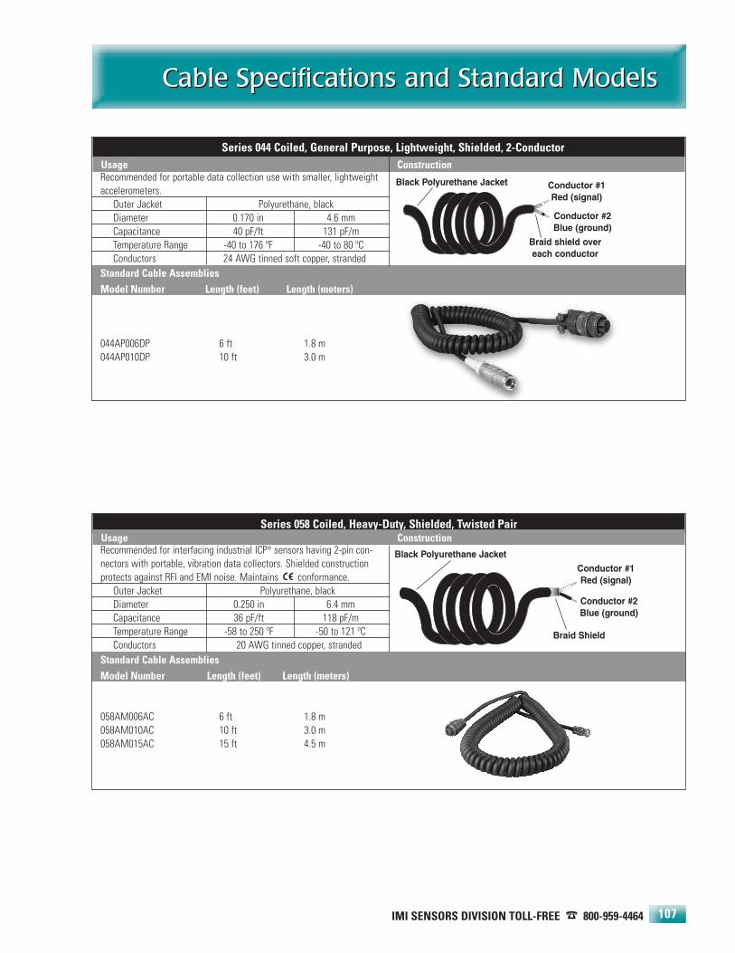
IMI SENSORS DIVISION TOLL-FREE � 800-959-4464
Cable Specifications and Standard ModelsCable Specifications and Standard Models
107
Recommended for portable data collection use with smaller, lightweightaccelerometers. .
Outer Jacket Polyurethane, blackDiameter 0.170 in 4.6 mmCapacitance 40 pF/ft 131 pF/mTemperature Range -40 to 176 ºF -40 to 80 ºCConductors 24 AWG tinned soft copper, stranded
Standard Cable AssembliesModel Number Length (feet) Length (meters)
044AP006DP 6 ft 1.8 m044AP010DP 10 ft 3.0 m
Series 044 Coiled, General Purpose, Lightweight, Shielded, 2-ConductorUsage Construction
Conductor #1Red (signal)
Conductor #2Blue (ground)
Black Polyurethane Jacket
Braid shield overeach conductor
Recommended for interfacing industrial ICP® sensors having 2-pin con-nectors with portable, vibration data collectors. Shielded constructionprotects against RFI and EMI noise. Maintains conformance.
Outer Jacket Polyurethane, blackDiameter 0.250 in 6.4 mmCapacitance 36 pF/ft 118 pF/mTemperature Range -58 to 250 ºF -50 to 121 ºCConductors 20 AWG tinned copper, stranded
Standard Cable AssembliesModel Number Length (feet) Length (meters)
058AM006AC 6 ft 1.8 m058AM010AC 10 ft 3.0 m058AM015AC 15 ft 4.5 m
Series 058 Coiled, Heavy-Duty, Shielded, Twisted PairUsage Construction
Conductor #1Red (signal)
Conductor #2Blue (ground)
Black Polyurethane Jacket
Braid Shield

Standard Cable AssembliesModel Number Length (feet) Length (meters)
050AE006AC 6 ft 1.8 m050AE010AC 10 ft 3.0 m
050BQ006AC 6 ft 1.8 m050BQ010AC 10 ft 3.0 m
050BR006AC 6 ft 1.8 m050BR010AC 10 ft 3.0 m
050FV006AC 6 ft 1.8 m050FV010AC 10 ft 3.0 m
050FV006CV 6 ft 1.8 m050FV010CV 10 ft 3.0 m
Series 050 Coiled, Lightweight, Shielded PairUsage Construction
24-HOUR SENSORLINESM 716-684-0003 • WEB SITE — www.imi-sensors.com
Cable Specifications and Standard ModelsCable Specifications and Standard Models
108
Recommended for interfacing industrial ICP® sensors having 2-pin con-nectors with portable, vibration data collectors. Shielded constructionprotects against RFI and EMI noise. .
Outer Jacket Thermal Plastic Elastimere (TPE), blackDiameter 0.210 in 5.3 mmCapacitance 31 pF/ft 94 pF/mTemperature Range -22 to 176 ºF -30 to 80 ºCConductors 23 AWG tinned copper, stranded
Braid shield overeach conductor
Conductor #1White (signal)
Conductor #2Black (ground)
Black TPE Jacket

IMI SENSORS DIVISION TOLL-FREE � 800-959-4464
Cable Specifications and Standard ModelsCable Specifications and Standard Models
109
Foil Shield
FEP Teflon Jacket
Recommended for use with industrial ICP® sensors having 2-pin connec-tors and in harsh environments, especially where cable may get pinchedor crushed. Shielded construction protects against RFI and EMI noise..
Outer Jacket Stainless steel over polyurethaneDiameter 0.410 in 10.4 mmCapacitance 36 pF/ft 118 pF/mTemperature Range -58 to 250 ºF -50 to 121 ºCConductors 20 AWG tinned copper, stranded
Standard Cable AssembliesModel Number Length (feet) Length (meters)
047AM010AC 10 ft 3.0 m
047AM010BZ 10 ft 3.0 m
Series 047 Steel Armored, Shielded, Twisted PairUsage Construction
22 AWG Drain Wire
Recommended for high temperature use with industrial ICP® sensorshaving 2-pin connectors and in harsh environments, especially wherecable may get pinched or crushed. Shielded construction protectsagainst RFI and EMI noise..
Outer Jacket Stainless steel over FEP TeflonDiameter 0.268 in 6.8 mmCapacitance between conductors
51 pF/ft 167 pF/m
Capacitance betweenconductor and shield
97 pF/ft 318 pf/m
Temperature Range -90 to 392 ºF -70 to 200 ºCConductors 18 AWG tinned copper, stranded
Standard Cable AssembliesModel Number Length (feet) Length (meters)
048BP010BZ 10 ft 3.0 m
048BP010AC 10 ft 3.0 m
Series 048 Steel Armored, High Temperature, Shielded, Twisted PairUsage Construction
Stainless Steel Armor Braid Shield
Polyurethane Jacket
Conductor #1Red (signal)
Conductor #2Blue (ground)
Conductor #1Red (signal)
Conductor #2Blue (ground)
Stainless Steel Armor Jacket
20 AWG Drain Wire

Series 062 Shielded, Twisted, 3-conductorUsage Construction
24-HOUR SENSORLINESM 716-684-0003 • WEB SITE — www.imi-sensors.com
Cable Specifications and Standard ModelsCable Specifications and Standard Models
110
Recommended for use with multi-axis industrial ICP® sensors in harshenvironments, especially where cable may get pinched or crushed.Shielded construction protects against RFI and EMI noise. .
Outer Jacket Stainless steel over polyurethaneDiameter 0.410 in 10.4 mmCapacitance 36 pF/ft 118 pF/mTemperature Range -58 to 250 ºF -50 to 121 ºCConductors 20 AWG tinned copper, stranded
Standard Cable AssembliesModel Number Length (feet) Length (meters)
043AN010BZ 10 ft 3.0 m043AN020BZ 20 ft 6.1 m
Series 043 Steel Armored, Shielded, Twisted, 4-conductorUsage Construction
Conductor #1Conductor #2
Conductor #3Conductor #4
Braid ShieldStainless Steel Armor
Polyurethane Jacket
Recommended for use in dedicated installations of dual output sensorsin high temperature environments or where chemical resistivity isimportant.
Outer Jacket Extruded FEP Teflon, bright orangeDiameter 0.190 in 4.8 mmCapacitance 27 pF/ft 88.6 pF/mTemperature Range -85 to 392 ºF -65 to 200 ºCConductors 20 AWG tin plated copper, stranded
Standard Cable AssembliesModel Number Length (feet) Length (meters)
056FY016BZ 16 ft 4.9 m056FY032BZ 32 ft 9.8 m056FY064BZ 64 ft 19.5 m
Series 056 High Temperature Shielded, Twisted, 3-conductorUsage Construction
Conductor #2Conductor #3
Conductor #1
Conductor #1White
Conductor #2Black
Conductor #3Red
Braid Shield
Orange FEP Teflon Jacket
Supplied as an integral cable with Series TO607 and TO608 sensors.Outer Jacket Polyurethane, blackDiameter 0.160 in 4.1 mmCapacitance 20 pF/ft 65 pF/mTemperature Range -65 to 250 °F -54 to 121 °CConductors 28 AWG tinned copper, stranded Braid Shield
Black Polyurethane Jacket
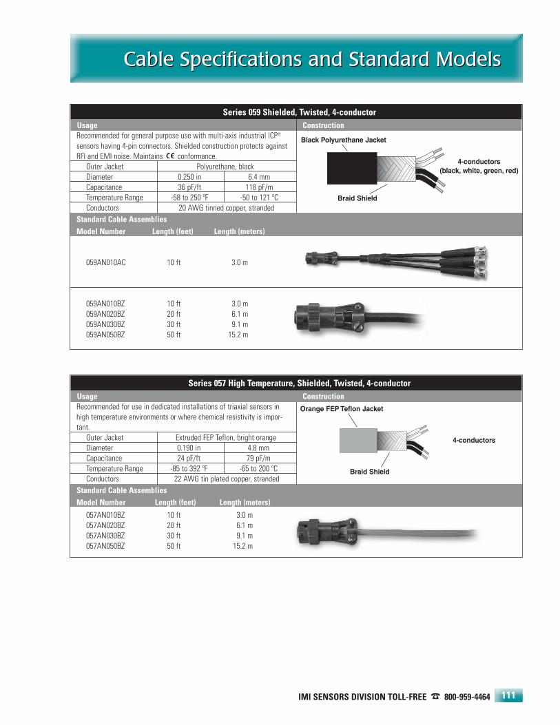
4-conductors(black, white, green, red)
Braid Shield
Black Polyurethane JacketRecommended for general purpose use with multi-axis industrial ICP®
sensors having 4-pin connectors. Shielded construction protects againstRFI and EMI noise. Maintains conformance..
Outer Jacket Polyurethane, blackDiameter 0.250 in 6.4 mmCapacitance 36 pF/ft 118 pF/mTemperature Range -58 to 250 ºF -50 to 121 ºCConductors 20 AWG tinned copper, stranded
Standard Cable AssembliesModel Number Length (feet) Length (meters)
059AN010AC 10 ft 3.0 m
059AN010BZ 10 ft 3.0 m059AN020BZ 20 ft 6.1 m059AN030BZ 30 ft 9.1 m059AN050BZ 50 ft 15.2 m
Series 059 Shielded, Twisted, 4-conductorUsage Construction
Standard Cable AssembliesModel Number Length (feet) Length (meters)
057AN010BZ 10 ft 3.0 m057AN020BZ 20 ft 6.1 m057AN030BZ 30 ft 9.1 m057AN050BZ 50 ft 15.2 m
IMI SENSORS DIVISION TOLL-FREE � 800-959-4464
Cable Specifications and Standard ModelsCable Specifications and Standard Models
111
4-conductors
Orange FEP Teflon JacketRecommended for use in dedicated installations of triaxial sensors inhigh temperature environments or where chemical resistivity is impor-tant..
Outer Jacket Extruded FEP Teflon, bright orangeDiameter 0.190 in 4.8 mmCapacitance 24 pF/ft 79 pF/mTemperature Range -85 to 392 ºF -65 to 200 ºCConductors 22 AWG tin plated copper, stranded
Braid Shield
Series 057 High Temperature, Shielded, Twisted, 4-conductorUsage Construction

24-HOUR SENSORLINESM 716-684-0003 • WEB SITE — www.imi-sensors.com
Cable Specifications and Standard ModelsCable Specifications and Standard Models
112
Recommended for use with interface boxes. Shielded construction pro-tects against RFI and EMI noise..
Outer Jacket Polyvinyl chloride, blackDiameter 0.610 in 15.5 mmCapacitance 23 pF/ft 76 pF/mTemperature Range -40 to 221 ºF -40 to 105 ºCConductors 20 AWG tinned copper, stranded
Standard Cable AssembliesModel Number Length (feet) Length (meters)
049BY010AD 10 ft 3.0 m
Standard Cable AssembliesModel Number Length (feet) Length (meters)
046EG010AD 10 ft 3.0 m
Series 049 Shielded, Twisted, 12-Pair (24 total conductors)Usage Construction
12 Twisted Pairs (24 total conductors)
Foil Shield
Black PVC Jacket
Recommended for use with 16-channel switch boxes that have a multi-ple output option. This approach is a cost effective method for connect-ing 16 measurement channels for continuous, on-line monitoring..
Outer Jacket Polyvinyl chloride, blackDiameter 0.70 in 17.8 mmCapacitance 23 pF/ft 75 pF/mTemperature Range -40 to 221 ºF -40 to 105 ºCConductors 20 AWG tinned copper, stranded
Series 046 Shielded, Twisted, 16-Pair (32 total conductors)Usage Construction
16 Twisted Pairs (32 total conductors)
Foil Shield
22 AWG Drain Wire
22 AWG Drain Wire
Black PVC Jacket

IMI SENSORS DIVISION TOLL-FREE � 800-959-4464
Cable Specifications and Standard ModelsCable Specifications and Standard Models
113
Conductor (signal)
Recommended for use as an output cable from signal conditioners andswitch boxes..
Outer Jacket Polyvinyl chloride, blackDiameter 0.193 in 4.9 mmCapacitance 29 pF/ft 95 pF/mTemperature Range -40 to 176 ºF -40 to 80 ºCConductor 20 AWG bare copper, solid
Standard Cable AssembliesModel Number Length (feet) Length (meters)
051AC010AC 10 ft 3.0 m
Series 051 Coaxial, Heavy Duty, Type RG58/UUsage Construction
Recommended for use in high temperature or corrosive environments,with ICP® sensors having coaxial connectors..
Outer Jacket FEP Teflon, Extruded, Tinned, BrownDiameter 0.140 in 3.6 mmCapacitance 15 pF/ft 49 pF/mTemperature Range -94 to 392 ºF -70 to 200 ºC
Conductor30 AWG silver plated,
copper covered steel, strandedStandard Cable AssembliesModel Number Length (feet) Length (meters)
054BP010AC 10 ft 3.0 m
Series 054 High Temperature CoaxialUsage Construction
Recommended for general purpose use with small size, high frequencyICP® sensors having coaxial connectors..
Outer Jacket FEP Teflon, whiteDiameter 0.075 in 1.9 mmCapacitance 29 pF/ft 95 pF/mTemperature Range -130 to 400 °F -90 to 204 °CConductor 30 AWG silver plated copper, stranded
Series 060 General Purpose, Small Diameter CoaxialUsage Construction
Black PVC Jacket Polyethylene Dielectric
Braid Shield (ground)
White FEP Teflon Jacket
Conductor (signal)
PTFE Dielectric
Braided Shield (ground)
Brown FEP Teflon Jacket PTFE Dielectric
Braid Shield (ground)
Conductor (signal)

24-HOUR SENSORLINESM 716-684-0003 • WEB SITE — www.imi-sensors.com
Mounting HardwareMounting Hardware
114
Vibration Sensor Mounting Pads
These mounting pads may be adhesively bonded orwelded to machinery surfaces at specific vibration sen-sor installation points. The pads ensure that periodicmeasurements are always taken from the exact samelocation, lending to more accurate and repeatablemeasurement data.
Pads with tapped holes are for use with stud mountedsensors whereas the untapped pads are intended foruse with magnetically mounted sensors.
For permanent installations, the pads facilitate mount-ing of sensors without actually machining the surfaceonto which they are to be installed. Also, the untappedpads may be utilized to achieve magnetic attraction onnon-ferrous surfaces.
All mounting pads are manufactured from resilient,stainless steel.
Magnetic Mounting Bases
Magnetic mounting offers the most convenientmethod of temporary sensor installation for route-based measurements and data collection.
IMI’s magnetic mounting bases feature rare-earth magnet elements to achieve high attraction forces tothe test structure. This aids in high frequency transmis-sibility and assures attraction for weighty sensors andconditions of high vibration.
Rail mount styles are utilized for curved surfaces, suchas motor housings and pipes. Knurled housings aid ingripping for removal. Hex shaped magnetic bases aredesigned for smaller high frequency sensors. All magnetic mounting bases are manufactured fromresilient, stainless steel.
Note: Exercise caution when installing magneticallymounted sensors by engaging the edge of the magnetwith the structure and carefully rolling the sensor/magnetassembly to an upright position. Never allow the magnet to impact against the structure as this maydamage the sensor by creating shock acceleration levels beyond survivable limits.
Vibration Sensor Mounting Pad Models
For Stud Mounted Sensors Diameter Tapped HoleModel 080A93* 0.75 in (19mm) 1/4-28 (M6 x 1.0) thread Model 080A118* 1 in (25mm) 1/4-28 (M6 x 1.0) thread Model 080A91* 1.375 in (35mm) 1/4-28 (M6 x 1.0) thread
For Magnetic Mounted SensorsModel 080A94 0.75 in N/AModel 080A92 1.375 in N/A
NOTES: *For models with metric dimensions, please use “M” prefix with modelnumber listed above.
Magnetic Mounting Base Models
For Flat Surfaces Diameter Thread Attraction ForceModel 080A120* 0.75 in (19 mm) 1/4-28 (M6 x 1.0) stud 15 lb (67 N)Model 080A121* 1 in (25 mm) 1/4-28 (M6 x 1.0) stud 35 lb (156 N)Model 080A122* 1.5 in (38 mm) 1/4-28 (M6 x 1.0) stud 50 lb (222 N)
For Curved SurfacesModel 080A130* 0.75 in (19 mm) 1/4-28 (M6 x 1.0) stud 15 lb (67 N)Model 080A131* 1 in (25 mm) 1/4-28 (M6 x 1.0) stud 35 lb (156 N)Model 080A132* 1.5 in (38 mm) 1/4-28 (M6 x 1.0) stud 55 lb (245 N)Model 080A133* 2 in (51 mm) 1/4-28 (M6 x 1.0) stud 85 lb (378 N)
For Small, High Frequency SensorsModel 080A157 0.375 in (9.5 mm) 5-40 female 2.5 lb (11 N)Model 080A101 0.75 in (19 mm) 10-32 male 12 lb (53 N)
NOTES: *For models with metric dimensions, please use “M” prefix with modelnumber listed above.

IMI SENSORS DIVISION TOLL-FREE � 800-959-4464
Mounting HardwareMounting Hardware
115
Mounting Stud Models
Studs Thread CommentModel 081A08 10-32 to 1/4-28 BeCu, no shoulderModel 081A30 1/4-28 to 1/4-28 SS, with shoulder, 0.365 in length Model 081B05 10-32 to 10-32 BeCu, with shoulderModel 081B20 1/4-28 to 1/4-28 BeCu, with shoulderModel 080A156 1/2-20 to 1/4-28 Use with 607A11, 607A61Model 080A162 3/4-16 to 1/4-28 Use with 607A01, 608A11Model 080A165 3/4-16 floating hex nut Use with 608A11Model M081B05 10-32 to M6 × 0.75 BeCu, no shoulderModel M081A61 1/4-28 to M6 × 1.0 BeCu, no shoulderModel M080A159 1/2-20 to M6 × 1.0 Use with M607A11, M607A61Model M080A163 3/4-16 to M6 × 1.0 Use with M607A01
Set Screws Thread CommentModel 081A39 10-32 SS with brass tip, socket head, 0.375 in lengthModel 081A40 1/4-28 SS with brass tip, socket head, 0.5 in lengthModel 081A41 1/4-28 SS with brass tip, socket head, 0.625 in length
Mounting Bolt Models
Studs Thread × Length UsageModel 081A56 1/4-28 × 0.75 in Series 629Model 081A68 1/4-28 × 0.88 in Series 604, 605, 606Model 081A57 1/4-28 × 1.05 in Series 624, 625AModel 081A67 1/4-28 × 1.12 in Captive style for Series 602Model 081M85 1/4-28 × 1.25 in Captive style for Series 624, 625AModel 081A73 1/4-28 × 1.34 in Series 625BModel 081A97 1/4-28 × 1.0 in Series 602, Model 635A01Model 081A76 1/4-28 × 0.94 in Model 631A80Model M081A59 M6 × 1.0 × 20 mm Series M629Model M081A68 M6 × 1.0 × 22.9 mm Series M604, M605, M606Model M081A58 M6 × 1.0 × 25.4 mm Series M624, M625AModel M081A73 M6 × 1.0 × 34 mm Series M625BModel M081A97 M6 × 1.0 × 25.4 mm Series M602, Model M635A01Model M081A76 M5 × 1.0 × 23.8 mm Model M631A80
Epoxy Kits
These epoxy kits provide a secure means for mounting accelerometers and adhesive mounting bases to machine structures.
Model 075A05Small Epoxy Kit
Model 075A06Large Epoxy Kit
Mounting Studs
Model 080A162Mounting Stud
Model 080A165Floating Hex Nut
Mounting Bolts
Mounting Studs and Bolts
Although each sensor is supplied with a mounting stud or bolt, it is good practice to keep a few spares on hand for usein the event of an unforeseen failure. The following tables provide guidelines for selecting the stud or bolt for use with aparticular sensor series. If in doubt, check the sensor specification sheet to determine the model of the recommendedstud or bolt.

24-HOUR SENSORLINESM 716-684-0003 • WEB SITE — www.imi-sensors.com
Mounting HardwareMounting Hardware
116
Spot Face Preparation Tools
Spot face tools provide an economical, simple meansfor preparation of machinery surfaces for vibration sen-sor installation. These tools are used with a standardhand drill to produce a smooth, flat surface, with aperpendicular pilot hole, that can be tapped with theappropriate sensor mounting thread.
Surface preparation, prior to installing sensors, is animportant consideration. A smooth, debris free surfacewill insure that high frequency vibrations are accurate-ly transmitted to the installed sensor. A perpendicular,tapped hole for stud or bolt-mounting of the sensor isalso important to avoid edge loading or the sensorbase and inaccurate measurements.
All spot face tools are manufactured from high-speedsteel and may be re-sharpened.
Triaxial Mounting Blocks
Adapts three individual accelerometers for conductingvibration measurements in three orthogonal axes. Hexsize listed represents the maximum allowable hex sizefor installed uni-axial accelerometers.
Spotface Preparation Tool Models
Model Spotface DiameterModel 080A127 1 in (25 mm)Model 080A128 1.25 in (32 mm)Model 080A129 1.5 in (38 mm)Model 080A134 2.25 in (57 mm)
Triaxial Mounting Block Models
Model Dimensions Material Mounting via Sensor fasteners Max. hexModel 080A62 1.23 in cube stainless stl. 10-32 screws 1/4-28 screws 7/8 inModel 080A57 1.48 in cube stainless stl. 10-32 screws 1/4-28 screws 1-1/4 in
Quick-Connect Mounting System
This two-part system permits rapid mounting and dis-mounting of 1/4-28 threaded sensors with a quick, 3/4-turn engagement. The 1 inch hex shaped mounting padis typically stud-mounted to machinery surfaces andleft as a measurement point locator for route basedmeasurements and data collection. The knurled, 1 inch(25 mm) diameter mounting base installs at the base ofthe stud or bolt-mounted sensor which is carried frompoint to point, engaged with the mounting pads fordata collection, and then disengaged. The system per-mits greater high frequency transmissibility than mag-netic mounted sensors. Both components are manu-factured from resilient, stainless steel.
Model 080A69Mounting Base
Model 081A69Mounting Pad
Model 080A62 Mounting Block
Model 080A57 Mounting Block

IMI SENSORS DIVISION TOLL-FREE � 800-959-4464
Mounting HardwareMounting Hardware
117
Motor Fin Mounting Stems
These stems are designed to be either epoxied or weld-ed in-between the cooling fins of large electric motors.The stems feature a flat mounting surface with a 1/4-28tapped hole to facilitate either stud, bolt or magneticmounting of vibration sensors. A variety of stem sizesaccommodate different motor sizes and cooling fingeometries.
All stems are manufactured from resilient, stainlesssteel.
Probe Tips
Probe tips install onto vibration sensors to enable theiruse as hand-held vibration probes. This technique isuseful if installation space is severely limited or fordetermining installation locations where vibration ismost prevalent. Caution is advised when using probetips since inaccuracies may result by factors such asapplied pressure and orientation of the probe.
All probe tips are manufactured from resilient, stainlesssteel and feature a tapped 1/4-28 threaded hole.
Motor Fin Mounting Stem Models
Model Stem Thickness Overall LengthModel 080A123 0.25 in (6.35 mm) 1.375 in (40 mm)Model 080A124 0.25 in (6.35 mm) 2.125 in (54 mm)Model 080A125 0.5 in (12.7 mm) 1.625 in (41 mm)Model 080A126 0.5 in (12.7 mm) 2.375 in (60 mm)
Probe Tip Models
Model Length Tapped HoleModel 080A107 2 in 1/4-28 threadModel 080A105 4 in 1/4-28 threadModel 080A108 8 in 1/4-28 thread

Model 699A02 Specifications
Dynamic Performance English SIFrequency (fixed, ± 1%) 159.2 Hz 159.2 HzAcceleration (± 3%) 1 g rms or pk 9.81 m/s2 rms or pkVelocity 0.39 in/sec rms or pk 9.81 mm/s rms or pkDisplacement 0.39 mil rms or pk 9.81 µm rms or pkTransverse Amplitude ≤ 3% ≤ 3%Distortion (0 to 250 gm load) ≤ 7% ≤ 7%Amplitude Control Closed Loop Closed LoopMaximum Sensor Weight 8.8 oz 250 gm
EnvironmentalTemperature Range +15 to +130 °F -10 to +55 °C
ElectricalRamp-up Time < 3 sec < 3 secBattery Type (4 required) 1.5 VDC Type “AA” 1.5 VDC Type “AA”Battery Life (with 250 gm load) 2.2 hours 2.2 hoursAuto shut-off cycle 60 to 150 sec 60 to 150 sec
MechanicalSensor Mounting Thread 1/4-28 UNF female 1/4-28 UNF femaleMaximum Mounting Torque 10 in-lb 112 N-cmSize (diameter × height) 2.2 × 7.8 in 56 × 198 mmWeight 31 oz 900 gm
Options (indicate using prefix letter shownM - Metric acceleration, 10.0 m/s2, (1.02 g) rms or pk
24-HOUR SENSORLINESM 716-684-0003 • WEB SITE — www.imi-sensors.com118
Portable ShakersPortable Shakers
Model 699A02
This hand-held, portable shaker delivers a controlled,1.0 g rms or 1 g pk vibration, at 159.2 Hz, for verifyingvibration sensor operation and sensitivity. The unitaccommodates sensors weighing up to 250 grams andis powered by four, standard “AA” type batteries. Anauto-shutoff feature preserves battery life, however,continuous operation is switch selectable and an exter-nal DC power supply (Model 073A16) is available.Included is a nylon carry pouch with carry strap/beltloop.

Technical InformationTechnical Information
119
PCB 716-684-0001 IMI Sensors Division toll-free 800-959-4464 Fax 716-684-3823 E-mail [email protected] Web site www.imi-sensors.com
Selection and implementation of industrial accelerometers
Accelerometer design and operating characteristics
Using the bias voltage as a diagnostic tool
Mounting techniques
Drilling and tapping instructions
Driving long cables
Unit conversions
Article reprints
Glossary of terms
Information to assist with machinery vibration analysis,predictive maintenance and condition based monitoring isreadily available through the following:
Professional Organizations
CMVA/ACVM (Canadian Machinery Vibration Association) Suite 877, 105 - 150 Crowfoot Crescent NWCalgary, AB T3G 3T2ph: (403) 208-9618 • fax: (403) 208-9619 • web: www.cmva.com
MFPT (Machinery Failure Prevention Technology)1877 Rosser LaneWinchester, VA 22601ph: (540) 678-8678 • fax: (540) 678-8799 • web: www.mfpt.org
Vibration Institute6262 S. Kingery HighwaySuite 212Willowbrook, IL 60527ph: (630) 654-2254 • fax: (630) 654-2271 • web: www.vibinst.org
Trade Magazines
InTechA Publication of ISA-The Instrumentation, Systems, and Automation Societyph: (919) 549-8411web: www.isa.org
Maintenance TechnologyApplied Technology Publications, Inc.1300 S. Grove Ave.Suite 105, Barrington, IL 60010ph: (847) 382-8100 • fax: (847) 304-8603web: www.mt-online.com
Power Industry Developmentweb: www.sterlingpublications.com/pub/powerind.htm
Reliability Magazine1704 Natalie Nehs Dr.Knoxville, TN 37931-4554ph: 865-531-2193 • fax: 865-531-2459web: www.reliability-magazine.com
Turbomachinery InternationalA Publication of Business Journals, Inc.50 Day StreetNorwalk, CT 06856-5550, USAphone: (203) 853-6015 • fax: (203) 852-8175web: www.turbomachinerymag.com
VibrationsA Publication of the Vibration Institute(see Professional Organizations above)
Publications
Basic Machinery VibrationsRonald L. Eshleman, Ph.D.,P.E.VIPress, IncorporatedISBN 0-9669500-0-3
Shock and Vibration HandbookCyril M. HarrisMcGraw-Hill, Inc.ISBN 0-07-026801-0

24-HOUR SENSORLINESM 716-684-0003 • WEB SITE — www.imi-sensors.com
Selection and Implementation ofIndustrial AccelerometersSelection and Implementation ofIndustrial Accelerometers
120
SELECTION AND IMPLEMENTATION OF INDUSTRIAL ACCELEROMETERS
OVERVIEW
Measuring, monitoring, analyzing, and trending machineryvibration data have become widely used methods fordetecting faults and diagnosing the health of bearings,gears, and other rotating machinery components. One ofthe key elements that has made these techniques so suc-cessful in today's condition based monitoring and predic-tive maintenance programs is the industrial accelerometer.These sensors are extremely rugged, provide a widedynamic range, and are designed to operate under a vari-ety of harsh conditions, including dirt, oil, submersion,high temperature, cryogenic temperature, and electro-magnetic noise. Since critical machinery comes in manyconfigurations and operating speeds, a wide selection ofindustrial accelerometers are available to suit the individ-ual installation and sensing requirements. This sectionprovides an overview of the selection and installation rec-ommendations for industrial accelerometers to ensureaccurate measurements and ultimately a successfulmachinery monitoring program.
SENSOR SELECTION
In order to perform adequately, each sensor must be ableto accurately measure the vibration frequencies andamplitudes of interest, in the desired units of measure. Anevaluation of measurement units, amplitude range, fre-quency range, and environmental factors is necessary toensure acceptable sensor performance. In addition, thesystem in which the sensor is to be used must be evaluat-ed. Issues such as whether the sensor will be permanent-ly installed or roved about; connected to a data collectioninstrument, FFT analyzer, PLC, or alarm system; whetherexcitation power is available from the readout instrumentor if a separate signal conditioner is required; whethervoltage signals, current signals, velocity units, or accelera-tion units will be monitored; and whether hazardous areaapprovals are necessary are among the key concerns thatmust be understood. In addition, interconnecting cablesmust also endure the environment and a plan for routinemaintenance, testing, and calibration of the equipmentmust be considered.
SELECT A VIBRATION UNIT OF MEASUREMENT
Ascertain which measurement units best represent thevibration changes that are to be detected. Quite often,
this decision is based upon historical data or commonpractice that may already be in place at the facility.Vibration may be represented with acceleration, velocity,or displacement units of measure. Industrial accelerome-ters generate an output signal that is proportional toacceleration over a very broad frequency range. Often, thisacceleration signal is electronically integrated into veloci-ty units of measure by the data collection or readoutinstrument. Velocity measurement units provide a greaterlevel of amplitude change at most machinery frequenciesof interest, whereas acceleration measurements are moreweighted at higher frequencies. Should an electronic inte-grator be unavailable, it may be desirable to use an indus-trial vibration sensor with a built-in integration circuit,which generates an output signal directly proportional toapplied velocity.
Additionally, vibration sensors are available with on-boardtemperature sensors, which provide a simultaneous out-put signal proportional to machine surface temperature.The temperature signal is used to provide an extra level ofprotection and warning, primarily for bearing monitoringapplications.
EVALUATE THE MEASUREMENT PARAMETERS ANDSENSOR CAPABILITIES
The selected sensor must be capable of responding to thevibration to be measured, which will have associated withit a frequency range of interest, in cpm or Hz, as well as aminimum and maximum amplitude range, in g (mm/s2)acceleration, or in/sec (mm/sec) velocity. The low frequen-cy range is derived from the slowest turning speed of themachine and any sub-harmonics associated with its oper-ation, including any coupled reduction gear, pulley speed,and any other related drive train or transmission factors.The high frequency of interest will be attributed to maxi-mum machine running speed, number of rolling elementbearings, gear mesh, and high frequency harmonics. Theacceptable operating levels of vibration amplitude mustbe determined in order to establish alarm or concern lim-its. This is often obtained through historical data, machin-ery manufacturer, or industry guideline. A low cost,portable vibration meter may be used to help establishacceptable vibration levels for machinery that is in satis-factory operating condition. Most vibration sensors willrespond to amplitudes well beyond acceptable vibrationlimits, however, for very low frequency and low amplitudevibration measurements, it is important to verify that thenoise floor of the sensor is low enough to accommodate

IMI SENSORS DIVISION TOLL-FREE � 800-959-4464
Selection and Implementation ofIndustrial Accelerometers
Selection and Implementation ofIndustrial Accelerometers
121
an accurate, low-level vibration measurement.
ENSURE SENSOR SURVIVABILITY AND ACCURACY
Once the vibration measurement parameters are understood,a thorough understanding of the environment, in which thesensor is to be used, is necessary. Many factors must be considered, including: temperature extremes, temperaturetransients, dirt, oil, moisture, humidity, structural bending andstrain, electromagnetic interference, radio frequency interfer-ence, ground loop potential, electrostatic discharge, exposureto harsh chemicals, exposure to high amplitude shock pulses,high frequency resonance, and radiation. For hazardous areasinvolving combustible vapors and dust, sensors carryingintrinsic safety approvals are available.
Fortunately, most IMI sensors incorporate design features,which help guard against many of these factors, however,before selecting any vibration sensor, the user should verify that the sensor under consideration will survive allenvironmental influences. The following highlights someof the important design features and benefits of IMI'svibration sensors.
Shear structured sensing elements - All IMI vibration sensorsutilize either quartz or ceramic piezoelectric sensing crystalsthat are stressed in a shear mode to generate their outputsignal. Whether these are annular shear or tri-shear elements,the benefits are the same. Shear structured elements are lesssusceptible to the effects of thermal transients, transversemotion, base bending, and case strain than other designs.This translates to fewer errors being introduced into themeasurement signal.
Typical shear structured industrial vibration sensor
Ceramic versus quartz sensing elements - Most IMI vibra-tion sensors utilize a ceramic sensing element, whichoffers the greatest signal-to-noise ratio due to excellent
resolution characteristics. However, when vibration ampli-tudes are high enough, such that noise floor is not a con-cern, sensors utilizing quartz-sensing crystals should beconsidered. Quartz sensors are much more stable overtime, meaning that their output sensitivity rarely shifts,and recalibration is not as critical. Also, quartz sensors areless susceptible to thermal transient errors as are ceramicsensors. Where it is difficult to remove a permanentlyinstalled sensor for routine calibration purposes, use asensor with a quartz-sensing element, if possible.
Laser welded, hermetically sealed construction - To guardagainst the influx of moisture, dirt, or oil, all IMI vibrationsensors are precision laser welded to provide a true her-metic seal. Each sensor is then leak tested for assurance.This ensures sensor survivability and performance even inadverse factory or field conditions, underwater, or duringwash down situations.
Stainless steel housings - All IMI vibration sensors utilize thisproven material, which stands up against many corrosivechemicals. IMI uses non-magnetic stainless steel, which provides shielding and averts errors due to electromagneticfields that may be present when operating on or near electricmotors.
Rugged MIL-spec hermetic connectors - Industrialaccelerometers wouldn't be industrial strength if they usedanything less than a rugged, military style connector orheavy-duty integral cable. Don't jeopardize your testingprogram with a sensor that has a flimsy cable or connec-tor whose pins might easily get bent or broken.
Internal shielding - EMI, ESD, RFI, and ground loops areundesirable in any measurement scenario. All IMI vibrationsensors incorporate an internal shield, which provideselectrical case isolation, to minimize any chance of noiseintroduction or data corruption due to EMI, ESD, RFI andground loops.
Sealed, integral cables - Although each IMI vibration sensoris hermetically sealed, electrical connections are subject tobeing shorted out, if submerged in conductive fluid. Unitswith sealed, integral cables eliminate the potential of anexposed electrical connection and permit operation undersubmerged or wash down conditions. Polyurethane cablesare best for submerged situations, whereas Teflon cables aremore resistant to adverse chemicals and high temperatures.

24-HOUR SENSORLINESM 716-684-0003 • WEB SITE — www.imi-sensors.com
Selection and Implementation ofIndustrial AccelerometersSelection and Implementation ofIndustrial Accelerometers
122
PERMANENT MOUNT VS. ROUTE BASED
Once the measurement requirements and environmental factors are fully understood, one must decide whether thesensor will be permanently installed to the machine or temporarily mounted for purposes of a route based data col-lection scenario. If the sensor is roved about for route baseddata collection, it must be capable of performing adequatelyand able to survive all of the environmental influences forevery collection point of the route. Several sensors may benecessary to accommodate a wide variety of requirementsalong a route. Permanently installed sensors need to survivethe one environment that they are placed in, however, thistypically is more demanding, since the location may be inac-cessible for a route based scenario, due to temperature orother extremes. Permanently installed sensors may be connected to a junction box where route based measure-ments are periodically taken or they may be implemented intoa continuous monitoring system.
Most machinery monitoring programs compare successivevibration measurements taken at the same point for trendingpurposes. With permanently installed sensors, this is accom-plished with the same sensor at the same location every time.When the sensor is permanently installed, it is practical to usea sensor that has undergone less stringent qualification testing, and may have a wider sensitivity tolerance, since successive measurements will still accurately indicate trends.For roving measurements, a sensor with a tight sensitivity tolerance is recommended since, if the sensor is changed,there will be less measurement shift due to sensor perform-ance. The point is that any change in measurement datamust be attributed to a change in machinery vibration, not achange in sensor characteristic or other factor.
SENSOR CALIBRATION AND PERFORMANCE
Every IMI sensor is supplied with calibration data that istraceable to NIST, however, some sensors are supplied withmore data than others. The reason for this is cost. A singlepoint calibration provides an output sensitivity value at onlyone reference frequency, which is typically 100 Hz (6000cpm). This single point calibration is provided for all low costsensors that are recommended for permanent installation. Afull calibration provides an entire frequency response plotover much of the sensor's specified frequency range. The fullcalibration typically spans from 10 Hz (600 cpm) to theupper 5% deviation frequency, and is provided for all preci-sion sensors that are recommended for roving, route-baseddata collection requirements, frequency analysis andmachinery diagnostic purposes.
Typical certificate including full calibration data
Low cost industrial vibration sensors may also have awider tolerance on their nominal sensitivity, which can beas much as 20% or more. This simply means that one spe-cific unit can have somewhat of a significant difference inoutput when compared to another unit of the samemodel. For example, if there is a ±20% sensitivity toler-ance on a 100 mV/g model, the actual sensitivity of anyunit could be anywhere from 80 mV/g to 120 mV/g. Thiscould be of concern if different units are used for con-ducting successive measurements at the same measure-ment point using the nominal sensitivity value. The resultingmeasured data could shift by as much as ±20% due tosensitivity tolerance and would contribute to measure-ment error if this were perceived as a change in vibrationamplitude. Note, however, that measured data obtainedwhen using the actual, supplied sensor sensitivity willnegate the wide tolerance of accuracy obtained whenusing the nominal, catalog sensitivity value. Although lowcost sensors are not tested as stringently as precision sensors, their measurement results are just as accuratewhen used as recommended. Another important, inherentcharacteristic that makes this possible is repeatability. AllIMI vibration sensors are extremely repeatable, as aremost piezoelectric sensors. Design factors that contributeto this property include a rigid sensing structure, no mov-ing parts, and solid-state circuitry. Repeatability is proba-bly the single most important requirement when conduct-

IMI SENSORS DIVISION TOLL-FREE � 800-959-4464
Selection and Implementation ofIndustrial Accelerometers
Selection and Implementation ofIndustrial Accelerometers
123
ing comparative measurements for trending purposes,which is why piezoelectric industrial vibration sensorshave become the sensors of choice for condition basedmonitoring and predictive maintenance applications. Alow cost unit used for successive measurements at thesame measurement point will yield vibration trend infor-mation that is just as accurate as if a precision sensor wereused.
Precision sensors, supplied with full calibration data, arebetter suited for roving, route-base data collectionrequirements, frequency analysis and machinery diagnos-tic purposes. These applications will typically demand atighter sensitivity tolerance for point-to-point measure-ment accuracy and potentially require frequency compen-sated measurements for greater analysis and diagnosticaccuracy. Precision sensors typically feature a sensitivitytolerance of ±5% and by referring to the provided full fre-quency response plot, exact sensitivity at any frequencycan easily be determined.
All sensors, whether permanently installed or used for rov-ing measurements, should be periodically calibrated. Theuse of a hand-held shaker provides a convenient, rapidtechnique for checking sensor sensitivity either in the labor at the installation point. Should a measurement ever beconsidered to be suspicious, it is good practice to moni-tor the full signal transmission path, or replace the sensor,to determine if the sensor, cabling, or signal conditioningequipment is at fault.
MOUNTING CONSIDERATIONS
There are several methods for securing vibration sensorsto machinery. These include stud mounting, adhesivemounting, and magnetic mounting. Additionally, the use ofa probe tip may be useful for very inaccessible measure-ment points, for locations where physical attachment of asensor is just not practical, or for determining installationlocations where vibration is most prevalent.
Each method will affect the frequency response attainable bythe vibration sensor since the mounted resonant frequency ofthe sensor/hardware assembly will be dependent upon itsmass and stiffness. The following diagram depicts how resonant frequency is affected by each mounting technique.
Effect of mounting technique on resonant frequency
Stud mounting is considered to be the best technique interms of being able to achieve the maximum attainablefrequency range. All sensor specifications and calibrationinformation supplied with the sensor are based upon studmounting during qualification tests. For best results, asmooth, flat surface should be prepared on the machinerysurface as well as a perpendicular tapped hole of properdimension. Spot face tools are available to simplify sur-face preparation. A thin layer of silicone grease or otherlubricant should be applied to the surface and the sensorshould be installed with the recommended mountingtorque. Be sure to follow all installation recommendationssupplied with each specific sensor model.
If drilling and tapping mounting holes into machinerystructures is not practical, adhesive mounting is the nextbest technique. Sensors may be secured directly withadhesive or a mounting pad with suitable tapped hole maybe adhesively attached or welded to the machinery surface. The sensor can then be stud mounted to theattached mounting pad.

24-HOUR SENSORLINESM 716-684-0003 • WEB SITE — www.imi-sensors.com
Selection and Implementation ofIndustrial AccelerometersSelection and Implementation ofIndustrial Accelerometers
124
Magnetic mounting is considered temporary and is widelyutilized for roving, route-based data collection scenarios.For non-magnetic machinery, steel, target locator pads, towhich the magnet will be attracted, may be welded oradhesively attached to the machine. The use of a targetlocator pad also helps insure that periodic vibration meas-urements are always taken at the same location. Cautionshould be exercised when applying magnetic mountedsensors to machinery surfaces. To avoid excessive shock,one should gently roll the sensor into place. Never allowthe magnet to impact against the structure as this maydamage the sensor.
Additional mounting hardware may be required for specialmounting scenarios. Mounting blocks are available formounting 2 or 3 sensors into a biaxial or triaxial array.Mounting stems are available for installation between thecooling fins of electric motors. Quick connect systemspermit rapid stud mounting from point to point for routebased data collection. For a qualified recommendation,discuss any unique mounting requirements with an appli-cation engineer.
INTERCONNECT CABLES
Twisted, two-conductor, shielded cable is recommended fortransmitting measurement signals from industrial vibrationsensors to readout, recording, data collection, and analysisinstruments. This type of cable offers the best shielding fromEMI, RFI, ESD, and other noise influences. Since all IMI indus-trial vibration sensors are insulated from ground, ground loopproblems are easily avoidable. The shield of the cable shouldbe drained to ground at only the instrumentation end, andremain floating at the sensor end. To conserve costs, coaxialcables may be used, however, there may be a sacrifice in theform of noise corruption. Materials of construction for cablesshould be selected to insure survivability in the environmentsin which they are used. Teflon cables are suitable for hightemperature use or where exposure to harsh chemicals is ofconcern. Sealed, integral cables should be used for sensorsthat are submerged or installed in areas of high humidity orsubjected to wash down. Armored cables offer additional
protection from being stepped on, rolled over, or sufferingnicks and cuts associated with machining debris and flyingmetal chips.
CONCLUSION
A successful condition based monitoring or predictivemaintenance program is heavily dependent upon accurate,repeatable vibration measurements of critical machinery.Piezoelectric industrial accelerometers have become thesensors of choice for providing such measurements in bothpermanently installed applications and for roving, routebased measurements. Many factors need to be consideredfor proper selection of vibration sensors including: the ability of the sensor to respond accurately to vibration frequencies and amplitudes of interest in the desired unitsof measure; survivability and accurate functionality of thesensor in the operating environment, determination as towhether the sensor will be permanently installed or rovedabout; technique used for attaching the sensor to themachine surface; amount of calibration information supplied with the sensor; whether hazardous area approvalis required; the type of cables used to connect to the sensors; and a plan for maintaining, testing and calibratingsensors.
A variety of sensor mounting techniques is available, however each has an impact on the frequency range capability of the measurement system. Interconnectcables should be selected to minimize effects of EMI, RFI,and ESD and be capable of surviving the environment inwhich they are used.
A close evaluation of the machinery operating conditions,a well-conceived approach to vibration monitoring, and adetailed analysis of sensor performance characteristicswill all lead to a more successful condition based monitoring or predictive maintenance program.

IMI SENSORS DIVISION TOLL-FREE � 800-959-4464
Accelerometer Design andOperating Characteristics
Accelerometer Design andOperating Characteristics
125
MECHANICAL CONSTRUCTION OF INDUSTRIALPIEZOELECTRIC ACCELEROMETERS
Accelerometers are transducers that are designed to produce an electrical output signal that is proportional toapplied acceleration. Several sensing technologies are utilized to construct accelerometers, including, straingage, piezoresistive, capacitive, and piezoelectric. Straingage, piezoresistive, and capacitive types possess theability to measure constant acceleration, such as that ofearth's gravity, whereas piezoelectric types can only accu-rately measure an acceleration that changes, such as thatencountered with vibration.
IMI Sensors manufactures both piezoelectric and capacitive industrial accelerometers. Piezoelectric typesare recommended for most every industrial vibrationapplication on rotating machinery. Capacitive types arereserved for extremely low frequency measurements, suchas that encountered with massive, slow-speed rollers.
Many applications for accelerometers exist in the researchand development sector on everything from computerdisk drive mechanisms to automobiles to advancedweapons systems. The primary focus for conducting accel-eration measurements in R&D applications is to minimizevibration experienced, or delivered, by an object in orderto extend service life, improve efficiency, or improve usercomfort. Applications for accelerometers in the industrialsector however, are primarily focused on extending servicelife of machinery by predicting failures, thus allowingmaintenance to be conducted in a planned manner. Bydoing so, operators can make more intelligent decisionsabout spare parts purchases and keep critical equipmentup-and-running longer and faster to increase product output and profitability.
Piezoelectric accelerometers are ideal for industrial vibra-tion monitoring applications. They can be made durable,protected from contamination, impervious to extraneousnoise influences, and are easy to implement.Accelerometers that are designed with these features areclassified as Industrial Accelerometers, i.e. suitable for usein rigorous industrial, field, or submersible environments.
The sensing element of a piezoelectric accelerometer utilizes
a polarized ceramic material or quartz crystal. Quartz is anatural piezoelectric material and has the advantages oflong-term stability, repeatability, and is non-pyroelectric,i.e. does not generate an output signal with change intemperature. Ceramic materials, on the other hand, havethe advantages of higher temperature operation, andhigher output signal - leading to a superior signal-to-noiseratio.
Both quartz and ceramic types are available with or with-out built-in signal conditioning electronics. Typically, theonly reason not to use an industrial accelerometer withbuilt-in electronics is when an extremely high temperatureenvironment (>325 °F (162 °C)) would damage the internalcircuitry. Otherwise, accelerometers with built in electron-ics, termed IEPE (Integrated Electronic PiezoElectric) orPCB's trademarked ICP® (Integrated Circuit Piezoelectric)designation offer superior ease of use, lower system cost,and greater distance signal transmission capability.Industrial ICP® accelerometers may also incorporate addi-tional features, such as a built in temperature sensing cir-cuitry, integration circuitry to convert to velocity units ofmeasure, transmitter circuitry to generate a 4 to 20 mAoutput signal, and TEDS (Transducer Electronic DataSheet) circuitry - an on-board, addressable memory withstored, self-identifying information.
The piezoelectric material within an accelerometer isstructured in a manner, which causes the material toundergo stress when under the influence of acceleration.This stress causes an electrical output that is linearly pro-portional to acceleration. The stress is achieved by plac-ing a seismic mass in intimate contact with the piezoelec-tric material. Since F=ma, any force applied to the piezo-electric material will be proportional to the seismic massand the applied acceleration. Since the seismic mass isconstant, the force, and resultant electrical output signal,becomes directly proportional to the applied acceleration.
There are several methods in which to stress the piezo-electric material with the seismic mass. These methods arecategorized in following terms that define the geometry ofthe sensing element - compression, flexural, and shear.Each has advantages and disadvantages that are high-lighted as follows:

24-HOUR SENSORLINESM 716-684-0003 • WEB SITE — www.imi-sensors.com
Accelerometer Design andOperating CharacteristicsAccelerometer Design andOperating Characteristics
126
Compression - permits compact construction, high stiff-ness, high durability, and high resonant frequency.Susceptible to inputs from base strain caused by thermaltransients and mounting on thin-walled structures.
Compression mode accelerometer
Flexural - generates higher output signals and is less susceptible to inputs from base strain. Lower resonant frequency and more fragile.
Flexural mode accelerometer
Shear - permits compact construction, good stiffness, gooddurability, and reasonable resonant frequency. Less susceptibleto inputs from base strain and thermal transients.
Shear mode accelerometer
For best overall performance in industrial machinery vibra-tion applications, IMI utilizes, almost exclusively, the shearstructured geometry for its piezoelectric industrialaccelerometers. Only one, ultra-high-output, low frequen-cy unit is offered that utilizes a flexural geometry.Compression geometries, although still utilized for someR&D applications, have been superseded by the sheartype for industrial applications, primarily due to the ther-mal transient induced base strain error susceptibility ofcompression designs, particularly at low frequencies. Thislow frequency error, or drift, causes what is commonlytermed "ski slope" error, which becomes evident whenacceleration signals are integrated into velocity signals.Volume production of shear style accelerometers has alsoreduced their cost to a level acceptable to the industrialmarket, further benefiting their use.
Industrial accelerometers have to endure severe environ-ments and tough operating conditions. In order to achievethese requirements, there are several design and con-struction characteristics that demand awareness. Inselecting an accelerometer for use in an industrial envi-ronment, ensure that the unit meets these design criteria:
Welded, stainless steel housing - All IMI accelerometersare constructed from stainless steel. This proven, corrosiveresistant material stands up well against dirt, oil, moisture,and harsh chemicals. Stainless steel is also non-magnetic,which minimizes errors induced when used in the vicinity ofelectric motors and other sources of electromagnetic inter-ference. For durability, all mating housing parts are precisionlaser welded. No epoxies are used which can eventuallyfatigue or cause leaks.
Internal faraday shield - All IMI accelerometers utilizean internal electrical shield to guard against ESD, RFI, EMI,and other extraneous noise influences. The result is an
Signal conditioningelectronics
Seismic mass
Piezoelectriccrystal
Preloadretaining ring

IMI SENSORS DIVISION TOLL-FREE � 800-959-4464
Accelerometer Design andOperating Characteristics
Accelerometer Design andOperating Characteristics
127
electrically, case-isolated sensing element that is insulatedfrom ground, which also insures that there will be noground loops in the measurement system that can causesignal drift, noise, and other hard-to-trace electrical problems.
Durable, military style electrical connectors orsealed, integral cables - IMI's electrical connectors offera true hermetic seal with glass-to-metal fusing of connectorpins and shells. All connectors are laser welded to the sensor housing. Sensors with integral cables incorporatehermetic feed through pins and high-pressure, injection-molded sealing of the cable to a metallic shell that is laserwelded to the sensor housing. Integral polyurethane jacketed cables offer 750 psi submersibility along with excellent pull strength and strain relief characteristics.
Interconnect cables should utilize shielded, twisted, con-ductor pairs and an outer jacket material that will surviveexposure to any media, or excessive temperatures presentin the environment in which it will be used. Stainless steel,armored cables are recommended for installations wheremachined debris or chips may damage cable jackets, orwhere cables have the potential of being stepped on orpinched. Electrical connectors for cables are offered in avariety of styles and configurations to suit the application.Take care to note the temperature rating of the connectorand material of construction. Environmentally sealedcable connectors provide a boot to protect the integrity ofthe connection in outdoor installations or during washdown episodes

Signal conditioningelectronics
Seismic mass
Piezoelectriccrystal
Preloadretaining ring
24-HOUR SENSORLINESM 716-684-0003 • WEB SITE — www.imi-sensors.com
Accelerometer Design andOperating CharacteristicsAccelerometer Design andOperating Characteristics
128
ELECTRICAL CHARACTERISTICS AND OPERATIONOF INDUSTRIAL ICP® ACCELEROMETERS
What is an ICP® Accelerometer?
Accelerometers are transducers that are designed to producean electrical output signal that is proportional to appliedacceleration. Industrial ICP® accelerometers rely on the piezo-electric effect of quartz crystals or polarized ceramics as thetransduction mechanism for converting mechanical forcesinto a proportional electrical signal. As crystals are stressed,charged ions accumulate at their surfaces. Electrodes that arein intimate contact with the crystals collect these ions, whichresult in an electrical signal. The signal is then transmitted viaa small wire to a signal conditioning circuit that is positionedwithin the accelerometer's housing. The signal conditioningcircuit serves to convert the difficult to use, high-impedance,charge signal from the crystal into a low-impedance, voltagesignal that can be transmitted outside of the accelerometerhousing, over a relatively long distance, without degradation.This low-impedance voltage signal can then be interrogatedby data collection equipment, displayed on an oscilloscope,stored on a recording instrument, or analyzed with a dataacquisition system or FFT analyzer. This type of accelerometeris generically termed an IEPE accelerometer for IntegratedElectronic PiezoElectric, or with PCB's trademark ICP®
accelerometer for Integrated Circuit Piezoelectric.
Shear structured ICP® accelerometer
How are accelerometer signals conditioned with built-inelectronics?
The heart of the signal conditioning circuitry within IMISensors' ICP® industrial accelerometers is a transistor. Thistransistor may be a JFET or MOSFET type, depending on thestyle of circuitry that is desired. The circuitry may take the formof a voltage amplifier, or a charge amplifier, depending on thesensor. Typically, voltage amplifiers are used with quartz crys-tal sensing elements, whereas charge amplifiers are used withpiezoelectric ceramic sensing elements. Each type of circuit
capitalizes on the inherent electrical characteristics of the particular sensing element to create a sensing device withoptimized performance. Additional circuitry may be added toenhance or tune the output signal for specific purposes. Suchenhancements include filtering, rms conversion, 4-20 mAtransmitters, integrators, and TEDS (Transducer ElectronicData Sheet - an on-board, addressable memory with stored,self-identifying information).
Schematic of voltage amplified and charge amplified ICP® accelerometer
What kind of electrical signals are generated by anICP® accelerometer?
As stated above, mechanical forces applied to the piezoelec-tric material generate a proportional electrical signal. If thisforce is positive going, then a positive electrical signal is generated. If this force is negative going, then a negative elec-trical signal is generated. Note that reversing the orientationof the crystals can reverse the output polarity. Regardless ofpolarity, this negative and positive going signal is delivered tothe integrated signal conditioning circuit. Since the integrated,transistorized circuit is an active electrical device, excitationpower is required to achieve operation. Typical excitation

IMI SENSORS DIVISION TOLL-FREE � 800-959-4464
Accelerometer Design andOperating Characteristics
Accelerometer Design andOperating Characteristics
129
power for an ICP® accelerometer is a positive voltage of 24VDC, which is regulated to a constant current value of 4 mA.Since, by design, the integrated signal conditioning circuit isenergized with only a positive voltage, it cannot deliver an out-put signal that swings negatively. To overcome this obstacle,the circuit is designed to operate at an elevated DC bias volt-age. The negative electrical signal generated by the piezoelec-tric material will swing negatively from this elevated DC biasvoltage toward zero, whereas the positive electrical signal generated by the piezoelectric material will swing positivelyfrom this elevated DC bias voltage toward the excitation voltage of 24 VDC.
VB = Sensor Bias Voltage of 10 VDCVs1 = Supply Voltage 1 = 24 VDCVE1 = Excitation Voltage 1 = Vs1-1 = 23 VDCVs2 = Supply Voltage 2 = 18 VDCVE2 = Excitation Voltage 2 = Vs2-1 = 17 VDCMaximum Sensor Amplifier Range = ± 10 volts
Effect of excitation voltage on dynamic range (headroom)
The bias voltage from sensor to sensor may vary but istypically within a range of 8 to 12 VDC. Allowing for a 2 voltconsumption by the circuitry, a minimum of 6 volts willremain to accommodate the signal excursion about thebias voltage. Most industrial ICP® accelerometers are
ranged for a ± 5 volt output swing to be well within thisrange. Should the sensor be driven beyond its normalrange, signal distortion or clipping can occur which will leadto measurement error. This error condition is also known as"running out of headroom". Note that some sensors aredesigned to operate at lower bias levels and / or be poweredfrom a lower excitation voltage. Either situation will result ina sensor that has less than the typical x± 5 volt outputswing, i.e. less headroom.
Here are typical accelerometer sensitivities, along withtheir ± 5 VDC output ranges:
Sensitivity ± 5 VDC output range1 mV/g ± 5000 g10 mV/g ± 500 g100 mV/g ± 50 g1000 mV/g ± 5 g10,000 mV/g ± 0.5 g
This relationship can be calculated for any sensitivityusing the following:
5000S = o.r.
where:S = Sensitivity (mV/g)o.r. = output range (g) for ± 5 VDC
How do ICP® accelerometers respond to step inputaccelerations and low frequency vibrations?
Piezoelectric accelerometers are AC coupled devices. Assuch, they are unable to provide a constant output signalwith respect to a constant acceleration, such as the 1 g gravitational acceleration of the earth. If exposed to a stepfunction of constant acceleration, the output of a piezoelec-tric accelerometer will initially follow the rise in accelerationamplitude, but then the output signal will decay back to zero.This decay occurs exponentially and at a rate that is governedby the value of the discharge time constant according to thefollowing equation:
q = Qe(-t/RC)
where:q = instantaneous charge (pC)Q = initial quantity of charge (pC)R = bias (or feedback) resistor value (ohm)C = total (or feedback) capacitance (pF)t = any time after t0 (seconds)e = base of natural log (2.718)

24-HOUR SENSORLINESM 716-684-0003 • WEB SITE — www.imi-sensors.com
Accelerometer Design andOperating CharacteristicsAccelerometer Design andOperating Characteristics
130
The longer the discharge time constant is, the longer ittakes for the decay to be completed. During the initialperiod of decay however, there is a short period of timewhen the output signal of the accelerometer is representativeof the constant value of acceleration "within a reasonableacceptable error". Consequently, once a "reasonableacceptable error" is established, limits can be calculated,which determine the rate-of-change of accelerationrequired in order to stay within the acceptable error. Theselimits become the slowest rate of acceleration change,which is specified as the low frequency range of theaccelerometer. Accelerometers with longer values of discharge time constant will have a lower frequency rangecapability. Many accelerometers are specified with severallow frequency ranges, along with their corresponding typical error values of 5%, 10%, and 3 dB. When measuringreciprocating or cyclic acceleration, as is encounteredwith vibration, ensure that the low frequency range of theaccelerometer meets the measurement frequency range ofinterest, within the reasonable acceptable error.
How do ICP® accelerometers respond to high-frequency vibrations?
Piezoelectric industrial accelerometers are very rigid struc-tures that conform to a single degree-of-freedom system.As such, their resonant frequency can be calculated fromthe relationship:
fn =ωω
= 1/2ππ ∗∗ √√k/m2ππ
where:
fn = the natural (resonant) frequencyωω = angular frequency in radiansk = force / deflection (stiffness)m = mass
This shows that resonant frequency is decreased asaccelerometer mass is increased. Rule-of-thumb permitsaccurate operation (within a + 5% sensitivity deviation) toapproximately one-fifth of the mounted resonant frequen-cy. Response to higher frequencies will be representedwith a greater increased sensitivity deviation, whichbecomes very substantial at the resonant frequency. SomeICP® accelerometers incorporate built-in, low-pass filtersto attenuate the mechanical gain induced at higher fre-quencies. This filtering may be especially desirable foraccelerometers that are used on rotating equipment thatis coupled to a variety of components operating at a vari-ety of frequencies. For example, a high frequency gear
mesh could introduce vibration that might cause saturationof an accelerometer that is attempting to measure a relatively lower frequency bearing vibration on the samedrive train. The following shows a typical, frequencyresponse plot for an industrial ICP® accelerometer.
Sensitivity Deviation vs Frequency
It is important to understand both the frequency range ofmeasurement interest and frequency range for theaccelerometer to be used for the application. If anaccelerometer is selected that does not have adequatefrequency range, measurement accuracy and ability todetect machinery faults will be compromised.
What is settling time?
Settling time is specified as the duration of time requiredfor the accelerometer to achieve a stable output signalwithin 1 percent of the specified bias voltage. Anotherterm used to describe this is warm-up time. Settling timebecomes a concern especially when acquiring datathrough a switch box, with a data collector that is providingexcitation power to the accelerometer. The settling time isthe minimum time that the data collection technicianmust wait before capturing any data. During the settlingtime, the output signal of the accelerometer will drift fromthe open circuit supply voltage, down to the bias voltage.This drift can introduce error in a measurement signal as itwill be perceived as low frequency measurement data bythe data collection or analysis equipment.

IMI SENSORS DIVISION TOLL-FREE � 800-959-4464
Accelerometer Design andOperating Characteristics
Accelerometer Design andOperating Characteristics
131
POWERING ICP® ACCELEROMETERS
All ICP® sensors require a constant current power sourcefor proper operation. A typical sensing system includes anICP® sensor, ordinary two conductor cable and a basicconstant current power supply.
Typical ICP® Sensor System
The signal conditioner consists of a well-regulated 18 to30 VDC source (battery or line-powered), a current-regu-lating diode (or equivalent constant current circuit), and acapacitor for decoupling (removing) the bias voltage fromthe measurement the signal. The voltmeter, VM monitorsthe sensor bias voltage (normally 8 to 12 VDC) and is use-ful for checking sensor operation and detecting open orshorted cables and connections.
The current-regulating device is used in place of a resistorfor several reasons. The very high dynamic resistance ofthe diode yields a source follower gain which is extremelyclose to unity and independent of input voltage. Also, thediode can be changed to supply higher currents for drivinglong cable lengths. Constant current diodes, as shown inFigure 2, should be used in ICP® signal conditioners. (Thecorrect orientation of the diode within the circuit is critical
for proper operation.) Except for special models, standardICP® sensors require a minimum of 2 mA for proper oper-ation.
Constant Current Diode
Present technology limits this diode type to 4 mA maxi-mum rating; however, several diodes can be placed in par-allel for higher current levels. All line-powered signal con-ditioners should use higher capacity (up to 20 mA) con-stant current circuits in place of the diodes, particularlywhen driving long signal cables (See page 132).
Decoupling of the data signal occurs at the output stageof the signal conditioner. A 10 to 30 µF capacitor shifts thesignal level to essentially eliminate the sensor bias volt-age. The result is a drift-free AC mode of operation.
Where do I find additional information?
Further information about the operation of ICP® andcharge mode piezoelectric sensors can be obtained byrequesting document PCB-G0001 or by visiting our websites: www.pcb.com and www.imi-sensors.com.
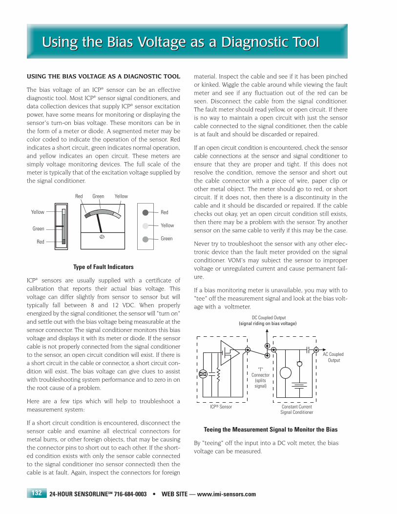
24-HOUR SENSORLINESM 716-684-0003 • WEB SITE — www.imi-sensors.com
Using the Bias Voltage as a Diagnostic ToolUsing the Bias Voltage as a Diagnostic Tool
132
USING THE BIAS VOLTAGE AS A DIAGNOSTIC TOOL
The bias voltage of an ICP® sensor can be an effectivediagnostic tool. Most ICP® sensor signal conditioners, anddata collection devices that supply ICP® sensor excitationpower, have some means for monitoring or displaying thesensor’s turn-on bias voltage. These monitors can be inthe form of a meter or diode. A segmented meter may becolor coded to indicate the operation of the sensor. Redindicates a short circuit, green indicates normal operation,and yellow indicates an open circuit. These meters aresimply voltage monitoring devices. The full scale of themeter is typically that of the excitation voltage supplied bythe signal conditioner.
Type of Fault Indicators
ICP® sensors are usually supplied with a certificate of calibration that reports their actual bias voltage. This voltage can differ slightly from sensor to sensor but will typically fall between 8 and 12 VDC. When properlyenergized by the signal conditioner, the sensor will “turn on”and settle out with the bias voltage being measurable at thesensor connector. The signal conditioner monitors this biasvoltage and displays it with its meter or diode. If the sensorcable is not properly connected from the signal conditionerto the sensor, an open circuit condition will exist. If there isa short circuit in the cable or connector, a short circuit con-dition will exist. The bias voltage can give clues to assistwith troubleshooting system performance and to zero in onthe root cause of a problem.
Here are a few tips which will help to troubleshoot a measurement system:
If a short circuit condition is encountered, disconnect thesensor cable and examine all electrical connectors formetal burrs, or other foreign objects, that may be causingthe connector pins to short out to each other. If the short-ed condition exists with only the sensor cable connectedto the signal conditioner (no sensor connected) then thecable is at fault. Again, inspect the connectors for foreign
material. Inspect the cable and see if it has been pinchedor kinked. Wiggle the cable around while viewing the faultmeter and see if any fluctuation out of the red can beseen. Disconnect the cable from the signal conditioner.The fault meter should read yellow, or open circuit. If thereis no way to maintain a open circuit with just the sensorcable connected to the signal conditioner, then the cableis at fault and should be discarded or repaired.
If an open circuit condition is encountered, check the sensorcable connections at the sensor and signal conditioner toensure that they are proper and tight. If this does notresolve the condition, remove the sensor and short outthe cable connector with a piece of wire, paper clip orother metal object. The meter should go to red, or shortcircuit. If it does not, then there is a discontinuity in thecable and it should be discarded or repaired. If the cablechecks out okay, yet an open circuit condition still exists,then there may be a problem with the sensor. Try anothersensor on the same cable to verify if this may be the case.
Never try to troubleshoot the sensor with any other elec-tronic device than the fault meter provided on the signalconditioner. VOM’s may subject the sensor to impropervoltage or unregulated current and cause permanent fail-ure.
If a bias monitoring meter is unavailable, you may with to“tee” off the measurement signal and look at the bias volt-age with a voltmeter.
Teeing the Measurement Signal to Monitor the Bias
By “teeing” off the input into a DC volt meter, the biasvoltage can be measured.

IMI SENSORS DIVISION TOLL-FREE � 800-959-4464
Mounting TechniquesMounting Techniques
133
MOUNTING TECHNIQUES
1.0 Installation Overview
When choosing a mounting method, both the advantagesand disadvantages of each technique should be closelyconsidered. Characteristics such as location, ruggedness,amplitude range, accessibility, temperature and portabilitymay be extremely critical. However, often times the mostimportant and overlooked consideration is the affect themounting technique will have on the high frequency oper-ating range of the accelerometer.
Shown below are six possible mounting techniques andtheir affect on the response of a typical piezoelectricaccelerometer. (Note that not all of the mounting methodsmay apply to your particular sensor.) By examining themounting configurations and corresponding graph, it canbe seen that the high frequency response of theaccelerometer may be compromised as mass is added tothe system and/or the mounting stiffness is reduced.
Effect of mounting technique on resonant frequency
Note: The low frequency response is unaffected by themounting technique. This roll-off behavior is typically fixedby the built-in sensor electronics. However, when operatingAC coupled signal conditioners with readout devices thathave an input impedance of less than 1 megohm, the lowfrequency range may be affected.
1.1 Stud Mount
This mounting technique requires smooth, flat contactsurfaces for proper operation and is recommended forpermanent and/or secure installations. Stud mounting isalso recommended when testing at high frequencies.
Note: Do NOT attempt mounting on curved, rough oruneven surfaces as the potential for misalignment and lim-ited contact surface may significantly reduce the sensorsupper operating frequency range.
1.1.1: First, prepare a smooth, flat mounting surface, andthen drill and tap a mounting hole in the center of thisarea according to the sensor’s installation drawing provided.
A precision machined mounting surface with a minimumfinish of 63 µin (0,00016 mm) is recommended. (If it is notpossible to properly prepare the machine surface, consid-er adhesive mounting as a possible alternative.) Be certainto inspect the area checking that there are no burrs orother foreign particles interfering with the contact surface.
1.1.2: Wipe clean the mounting surface and spread on alight film of grease, oil or similar coupling fluid prior toinstallation.
Adding a coupling fluid improves vibration transmissibilityby filling small voids in the mounting surface. This conse-quently increases the mounting stiffness. For permanentmounting, substitute epoxy or other type of adhesive.
Applying a thin film of grease
1.1.3: Hand tighten the sensor/mounting stud to themachine and secure the device by applying the recom-mended mounting torque.
It is important to use a torque wrench during this step asunder torquing the sensor may not adequately couple thedevice, while over torquing may result in stud failure.

24-HOUR SENSORLINESM 716-684-0003 • WEB SITE — www.imi-sensors.com
Mounting TechniquesMounting Techniques
134
1.2 Adhesive Mount
Adhesive mounting is often used for temporary installa-tions or where the machine surface cannot be adequatelyprepared for stud mounting. Adhesives such as hot glueand wax work well for temporary mounts whereas two-partepoxies and quick bonding gels provide a more permanentmount.
Note: Adhesively mounted sensors often exhibit a reduc-tion in high frequency range. In general, smooth surfacesand stiff adhesives will provide the best frequencyresponse. Contact the factory for recommended epoxies.
1.2.1 - Use of Separate Adhesive Mounting Base
This method involves mounting a base to the machine sur-face and then securing the sensor to this base. This allowsfor easy removal of the accelerometer.
Installation of an adhesive mounting base
1.2.1.1: Prepare a smooth, flat mounting surface. A min-imum surface finish of 63 µin (0,00016 mm) generallyworks best.
1.2.1.2: Stud mount the sensor to the appropriate adhe-sive mounting base according to the guidelines set forth in'1.1.2' and '1.1.3' of the Standard Stud Mount Procedure.Clean surface thoroughly to rid of grease or oil, then placea small portion of adhesive on the under side of the sensor.
1.2.1.3: Place a small portion of adhesive on the underside of the mounting base. Then, firmly press down on theassembly to displace any extra adhesive remaining underthe base.
1.2.2 - Direct Adhesive Mount
For restrictions of space, mass and/or convenience, mostsensors (with the exception of integral stud models) canbe directly adhesively mounted to the machine surface.
1.2.2.1: Prepare a smooth, flat mounting surface. A min-imum surface finish of 63 µin (0,00016 mm) generallyworks best.
1.2.2.2: Clean surface thoroughly to rid of grease or oil,then place a small portion of adhesive on the under side ofthe sensor. Firmly press down on the top of the assemblyto displace any adhesive. Be careful as excessive amountsof adhesive may make sensor removal difficult.
Direct adhesive mounting of a sensor
1.3 Magnetic Mount
Magnetic mounting provides a convenient method forportable measurements and is commonly used formachinery monitoring and other portable or trendingapplications.
Note: The correct choice of magnet and an adequatelyprepared mounting surface is critical for obtaining reliablemeasurements, especially at high frequencies. Poor instal-lations can cause as much as a 50% drop in the sensor fre-quency range.
Methods of magnetically mounting
Not every magnet is suitable for all applications. For example,rare earth magnets are commonly used because of their highstrength. Flat magnets work well on smooth, flat surfaces,while dual-rail magnets are required for curved surfaces. In thecase of non-magnetic or rough surfaces, it is recommended to first weld, epoxy or otherwise adhere a magnetic steelmounting pad to the test surface. This will provide a smoothand repeatable location for mounting.

IMI SENSORS DIVISION TOLL-FREE � 800-959-4464
Mounting TechniquesMounting Techniques
135
1.3.1: After choosing the correct magnet type, inspectthe unit checking that the mounting surfaces are flat andsmooth.
1.3.2: Stud mount the accelerometer to the appropriatemagnet according to the guidelines set forth in 'STEP 2'and '1.1.3' of the Standard Stud Mount Procedure.
1.3.3: Prepare a smooth, flat mounting surface. A mini-mum surface finish of 63 µin (0,00016 mm) generally worksbest. Then, after cleaning the surface and checking forburrs, wipe on a light film of silicone grease, machine oil orsimilar type coupling fluid.
1.3.4: Mount the magnet/sensor assembly to the pre-pared test surface by "rocking" or "sliding" it into place.
How and how not to engage a magnetic mounted sensor
Note: Carelessly magnetically mounting accelerometershas the potential to generate very high and potentiallydamaging 'g' levels. To withstand this abuse, be certain thesensor has built-in shock protection. If unsure, contactIMI.
1.4 Hand-held Probe Tip
This method is NOT recommended for most applications.It is generally used only for machinery monitoring andother portable trending applications. Both the accuracyand repeatability at the low (<5Hz) and high frequency(>1000 Hz) ranges are questionable.
DRILLING AND TAPPING INSTRUCTIONS
To insure proper results, when possible, refer to the installation instructions that have been supplied for the specific sensor to be installed. The following instructions are provided as a convenience.

24-HOUR SENSORLINESM 716-684-0003 • WEB SITE — www.imi-sensors.com
Driving Long CablesDriving Long Cables
136
DRIVING LONG CABLES
Operation over long cables may affect the frequencyresponse of ICP® accelerometers, and introduce low frequency noise and high frequency distortion when aninsufficient current is available to drive cable capacitance.
Unlike charge mode systems, where the system noise is afunction of cable length, ICP® sensors provide a high voltage, low impedance output well-suited for driving longcables through harsh environments. While there is virtuallyno increase in noise with ICP® sensors, the capacitiveloading of the cable may distort or filter higher frequencysignals depending on the supply current and the outputimpedance of the sensor.
Generally, this signal distortion is not a problem with lowerfrequency testing within a range up to 1,000 Hz. However,for higher frequency vibration, shock or transient testingover cables longer than 500 ft. , the possibility of signaldistortion exists.
The maximum frequency that can be transmitted over a given cable length is a function of both the cable capac-itance and the ratio of the peak signal voltage to the current available from the signal conditioner according to:
f(max) =109
2ππCV / (Ic-1)
where:
f(max)= maximum frequency (hertz)C = cable capacitance (picofarads)V = maximum peak output from sensor (volts)Ic = constant current from signal conditioner (mA)109 = scaling factor to equate units
Note that in this equation, 1 mA is subtracted from the total current supplied to sensor (Ic). This is done tocompensate for powering the internal electronics.
When driving long cables, Equation 1 shows that as thelength of cable, peak voltage output or maximum frequencyof interest increases, a greater constant current will berequired to drive the signal.
The cable driving nomograph provides a simple, graphicalmethod for obtaining the expected maximum frequencycapability of an ICP® measurement system. The maximumpeak signal voltage amplitude, cable capacitance and supplied constant current must be known or presumed.
For example, when running a 100 ft. (30.5 m.) cable with acapacitance of 30 pF/ft, the total capacitance is 3000 pF.This value can be found along the diagonal cable capaci-tance lines. Assuming the sensor operates at a maximumoutput range of 5 volts and the constant current availablefrom the power supply is 2 mA, the ratio on the verticalaxis can be calculated to equal 5. The intersection of thetotal cable capacitance and this ratio result in a maximumfrequency of approximately 10.2 kHz.
The nomograph does not indicate whether the frequencyamplitude response at a point is flat, rising or falling. Forprecautionary reasons, it is good general practice toincrease the constant current (if possible) to the sensor(within its maximum limit) so that the frequency deter-mined from the nomograph is approximately 1.5 to 2times greater than the maximum frequency of interest.
Note that higher current levels will deplete battery-pow-ered signal conditioners at a faster rate.
Also, any current not used by the cable goes directly topower the internal electronics and will create heat. This maycause the sensor to exceed its maximum temperature speci-fication. For this reason, do not supply excessive current overshort cable runs or when testing at elevated temperatures.

IMI SENSORS DIVISION TOLL-FREE � 800-959-4464
Cable Driving NomographCable Driving Nomograph
137
Frequency (Hz)
(Ratio of MaximumOutput Voltage fromSensor to AvailableConstant Current)
VIc - 1

24-HOUR SENSORLINESM 716-684-0003 • WEB SITE — www.imi-sensors.com
Conversions and Useful FormulasConversions and Useful Formulas
138
ACCELERATION
acceleration of gravity (g) 9.80665 meters/second2
32.174 feet/second2
386.088 inches/second2
feet/second2 0.3048 meters/second2
inches/second2 0.02540 meters/second2
PRESSURE
newtons/sq. centimeter 1.450 pounds/sq. inch
pounds/sq. foot 0.19242 inches of H2O
47.880 N/m2 (Pa)
psi 0.06805 atmospheres
0.06895 bars
2.036 inches of Hg
27.708 inches of H2O
703.77 mm of H2O
51.72 mm of Hg
0.68948 N/cm2
6 894.8 N/m2 (Pa)
7.031 x 10⁻⁴ kg (f) mm2
dB (sound pressure-air) 20 log P/Po
Po = 0.0029 x 10⁻⁶ psi
FORCE
kilogram (force) 9.80665 newtons
1.00 kilopond
newton 105 dynes
0.1020 kilogram (force)
3.597 ounce (force)
0.2248 pound (force)
7.2330 poundal
pound (force) 16.00 ounce (force)
0.45359 kilogram (force)
4.448 newtons
TEMPERATURE
Celsius to Fahrenheit °F = 9/5 °C +32
Fahrenheit to Celsius °C = (°F –32) 5/9
Fahrenheit to Kelvin °K = 5/9(°F + 459.67)
Fahrenheit to Rankin °R = °F + 459.67°
COMMONLY USED PREFIXES
G giga 109
M mega 106
k kilo 103
c centi 10-2
m milli 10-3
µ micro 10-6
n nano 10-9
p pico 10-12

IMI SENSORS DIVISION TOLL-FREE � 800-959-4464
Article ReprintsArticle Reprints
139
(AR-1) Application of Integrated-Circuits toPiezoelectric Transducers, Paper P4-2 PHYMID 67. ICP®
Sensor - Basic operation & application/CornellAeronautical Lab, R. W. Lally, 1967.
(AR-3) Piezoelectric Analogies - Electrostatic vs.hydrostatic system. Piezoelectric vs. hydraulic circuit, R.W.Lally, 1967.
(AR-4) Guide to ICP® Instrumentation - Voltage vs.charge systems. Effect of coupling & time constant onresponse. Powering ICP® system, R.W. Lally, 1971.
(AR-9) Testing the Behavior of Structures, R.W. Lally,PCB Piezotronics
(AR-18) Introduction to Piezoelectric Sensors - Basicaccelerometer, pressure, and force sensor design consid-erations & typical applications, J.F. Lally, 1985.
(AR-19) Calibration of Piezo Sensors - Calibration sys-tems for dynamic pressure sensors, force sensors, andaccelerometers with typical calibration results, J.F. Lally,1985.
(AR-28) Accelerometer Calibration: Is It Credible?, J.F.Lally, PCB Piezotronics
(AR-33) Diagnosing Faults in Rolling Element Bearings -J. Charles Berggren, Monsanto Chemical Company
(AR-40) Stability Considerations in MachineryMonitoring Vibration Instrumentation, D.M. Lally, PCBPiezotronics
(AR-43) The Trouble with Cables, J.F. Lally, PCBPiezotronics
(AR-59) Recommended Practices: AccelerometerCable, Wiring, and Connections, J.F. Lally, PCB Piezotronics
(AR-71) Reduction of the Ski Slope Effect WhenIntegrating from Acceleration to Velocity, R.I. Lemieux, IMI
(AR-72) Lower Accelerometer Cost By ReducingCalibration Requirements, E. Saller, IMI
(AR-73) Design & Selection of Vibration Sensors, E.Saller, IMI
(AR-74) Predicitive Maintenance at Tonawanda Forge,E. Saller, Gary Magaris, Kim Abernathey, Art Sauer
(AR-75) Selecting Accelerometers for High FrequencyMeasurements, E. Saller and D. Brzezowski, IMI
(AR-76) Continuous Condition Monitoring withVibration Transmitters and Plant PLCs, E. Saller.
To order copies of the following articles, simply request the "AR" number preceding each article; just write or call theIMI Marketing Department at: 716-684-0003.

24-HOUR SENSORLINESM 716-684-0003 • WEB SITE — www.imi-sensors.com
Glossary of TermsGlossary of Terms
140
Reprinted with permission from Application Note: AN 243-1,“Effective Machinery Measurements Using Dynamic SignalAnalyzers,” Hewlett-Packard Company, 1991. Editing and additionsperformed by PCB Piezotronics, Depew, NY, 1998.
Acceleration — The time rate of change of velocity. Typical units areft/s2, meters/s2, and G’s (1G = 32.17 ft/s2 = 9.81 m/s2).Acceleration measurements are usually made with accelerom-eters.
Accelerometer — Transducer whose output is directly proportionalto acceleration. Most commonly use piezoelectric crystals toproduce output.
Aliasing — A phenomenon which can occur whenever a signal isnot sampled at greater than twice the maximum bandwidth ofthe signal. Causes high frequency signals to appear at low fre-quencies. Aliasing is minimized by filtering the signal to a band-width less than ½ the sample rate. When the signal starts at 0Hz (baseband signals), bandwidth can be exchanged to maxi-mum frequency in the definition above.
Alignment — A condition whereby the axes of machine componentsare either coincident, parallel, or perpendicular, according todesign requirements.
Amplification Factor (Synchronous) — A measure of the suscep-tibility of a rotor to vibration amplitude when rotational speed isequal to the rotor natural frequency (implies a flexible rotor). Forimbalance type excitation, synchronous amplification factor iscalculated by dividing the amplitude value at the resonant peakby the amplitude value at a speed well above resonance (asdetermined from a plot of synchronous response vs. rpm).
Amplitude — The magnitude of dynamic motion or vibration.Amplitude is expressed in terms of peak-to-peak, zero-to-peak,or rms. For pure sine waves only, these are related as follows:rms = 0.707 times zero-to-peak; peak-to-peak = 2 times zero-to-peak. DSAs generally read rms for spectral components, andpeak for time domain components.
Anti-Aliasing Filter — Most commonly a low-pass filter designed tofilter out frequencies higher than ½ the sample rate in order tominimize aliasing.
Anti-Friction Bearing — See Rolling Element Bearing.
Asymmetrical Support — Rotor support system that does not pro-vide uniform restraint in all radial directions. This is typical formost heavy industrial machinery where stiffness in one planemay be substantially different than stiffness in the perpendicu-lar plane. Occurs in bearings by design, or from preloads suchas gravity or misalignment.
Asynchronous — Vibration components that are not related torotating speed (also referred to as nonsynchronous).
Attitude Angle (Steady-State) — The angle between the directionof steady-state preload through the bearing centerline, and aline drawn between the shaft centerline and the bearing center-line. (Applies to fluid-film bearings.)
Auto Spectrum (Power Spectrum) — DSA spectrum display whosemagnitude represents the power at each frequency, and whichhas no phase.
Averaging — In a DSA, digitally averaging several measurements toimprove accuracy or to reduce the level of asynchronous com-ponents. Refer to definitions of rms, time, and peak-hold aver-aging.
Axial — In the same direction as the shaft centerline.
Axial Position — The average position, or change in position, of arotor in the axial direction with respect to some fixed referenceposition. Ideally the reference is a known position within thethrust bearing axial clearance or float zone, and the measure-ment is made with a displacement transducer observing thethrust collar.
Balancing Resonance Speed(s) — A rotative speed that corre-sponds to a natural resonance frequency.
Balanced Condition — For rotating machinery, a condition wherethe shaft geometric centerline coincides with the mass center-line.
Balancing — A procedure for adjusting the radial mass distributionof a rotor so that the mass centerline approaches the rotor geo-metric centerline.
Band-Pass Filter — A filter with a single transmission band extend-ing from lower to upper cutoff frequencies. The width of theband is normally determined by the separation of frequencies atwhich amplitude is attenuated by 3 dB (a factor 0.707 ).
Bandwidth — The distance between frequency limits at which aband-pass filter attenuates the signal by 3 dB. In a DSA, themeasurement bandwidth is equal to [(frequency span)/(numberof filters) x (window factor)]. Window factors are: 1 for uniform,1.5 for Hanning, and 3.4 for flat top (P301) and 3.6 for flat top(P401). See flat top for more information.
Baseline Spectrum — A vibration spectrum taken when a machineis in good operating condition; used as a reference for monitor-ing and analysis.
Blade Passing Frequency — A potential vibration frequency on anybladed machine (turbine, axial compressor, fan, etc.). It is rep-resented by the number of blades times shaft-rotating frequen-cy.
Block Size — The number of samples used in a DSA to compute theFast Fourier Transform. Also the number of samples in a DSAtime display. Most DSAs use a block size of 1024. Smaller blocksize reduces frequency resolution.
Bode — Rectangular coordinate plot of 1x component amplitude andphase (relative to a keyphasor) vs. running speed.
BPFO, BPFI — Common abbreviations for ball pass frequency ofdefects on outer and inner bearing races, respectively.
Bow — A shaft condition such that the geometric centerline of theshaft is not straight.
Brinneling (False) — Impressions made by bearing rolling elementson the bearing race; typically caused by external vibration whenthe shaft is stationary.
Calibration — A test during which known values of the measuredvariable are applied to the transducer or readout instrument,and output readings varied or adjusted.

IMI SENSORS DIVISION TOLL-FREE � 800-959-4464
Glossary of TermsGlossary of Terms
141
Campbell Diagram — A mathematically constructed diagram usedto check for coincidence of vibration sources (i.e. 1 x imbalance,2 x misalignment) with rotor natural resonances.The form of thediagram is like a spectral map (frequency versus rpm), but theamplitude is represented by a rectangular plot, the larger theamplitude the larger the rectangle. Also known as an interfer-ence diagram.
Cascade Plot — See Spectral Map.
Cavitation — A condition which can occur in liquid-handling machin-ery (e.g. centrifugal pumps) where a system pressure decreasein the suction line and pump inlet lowers fluid pressure andvaporization occurs. The result is mixed flow which may pro-duce vibration.
Center Frequency — For a bandpass filter, the center of the trans-mission band, measured in a linear scale.
Charge Amplifier — Amplifier used to convert accelerometer outputimpedance from high to low, making calibration much lessdependent on cable capacitance.
Coherence — Measures how much of the output signal is depend-ent on the input signal in a linear and time-invariant way. It is aneffective means of determining the similarity of vibration at twolocations, giving insight into the possibility of cause and effectrelationships.
Constant Bandwidth Filter — A band-pass filter whose bandwidthis independent of center frequency. The filters simulated digital-ly by the FFT in a DSA are constant bandwidth.
Constant Percentage Bandwidth — A band-pass filter whosebandwidth is a constant percentage of center frequency. 1/3octave filters, including those synthesized in DSAs, are con-stant percentage bandwidth.
Critical Machinery — Machines which are critical to a major part ofthe plant process. These machines are usually unspared.
Critical Speeds — In general, any rotating speed which is associat-ed with high vibration amplitude. Often, the rotor speeds whichcorrespond to natural frequencies of the system.
Critical Speed Map — A rectangular plot of system natural fre-quency (y-axis) versus bearing or support stiffness (x-axis).
Cross Axis Sensitivity — A measure of off-axis response of veloc-ity and acceleration transducers.
Cycle — One complete sequence of values of a periodic quantity.
Damping — The quality of a mechanical system that restrains theamplitude of motion with each successive cycle. Damping ofshaft motion is provided by oil in bearings, seals, etc.The damp-ing process converts mechanical energy to other forms, usual-ly heat.
Damping, Critical — The smallest amount of damping required toreturn the system to its equilibrium position without oscillation.
Decibels (dB) — A logarithmic representation of amplitude ratio,defined as 10 times the base ten logarithm of the ratio of themeasured power to a reference. dBV readings, for example, arereferenced to 1 volt rms. dB amplitude scales are required todisplay the full dynamic range of a DSA. dB values for power orvoltage measurements yields the same result.
Degrees of Freedom — A phrase used in mechanical vibration todescribe the complexity of the system. The number of degreesof freedom is the number of independent variables describingthe state of a vibrating system.
Digital Filter — A filter which acts on the data after it has been sam-pled and digitized. Often used in DSAs to provide anti-aliasingprotection before internal re-sampling.
Differentiation — Representation in terms of time rate of change.For example, differentiating velocity yields acceleration. In aDSA, differentiation is performed by multiplication by jw in thefrequency domain, where w is frequency multiplied by 2p.(Differentiation can also be used to convert displacement tovelocity.)
Discrete Fourier Transform — A procedure for calculating discretefrequency components (filters or lines) from sampled time data.Since the frequency domain result is complex (i.e., real andimaginary components), the number of frequency points isequal to half the number of time samples (for a real FFT). Whenusing zoom analysis, the FFT uses complex time data and thenthe number of frequency lines is equal to the number of timesamples.
Displacement — The change in distance or position of an object rel-ative to a reference.
Displacement Transducer — A transducer whose output is propor-tional to the distance between it and the measured object (usu-ally the shaft).
DSA — See Dynamic Signal Analyzer.
Dual Probe — A transducer set consisting of displacement andvelocity transducers. Combines measurement of shaft motionrelative to the displacement transducer with velocity of the dis-placement transducer to produce absolute motion of the shaft.
Dual Voting — Concept where two independent inputs are requiredbefore action (usually machine shutdown) is taken. Most oftenused with axial position measurements, where failure of a sin-gle transducer might lead to an unnecessary shutdown.
Dynamic Motion — Vibratory motion of a rotor system caused bymechanisms that are active only when the rotor is turning atspeeds above slow roll speed.
Dynamic Signal Analyzer (DSA) — Vibration analyzer that usesdigital signal processing and the Fast Fourier Transform to dis-play vibration frequency components. DSAs also display thetime domain and phase spectrum, and can usually be inter-faced to a computer.
Eccentricity, Mechanical — The variation of the outer diameter of ashaft surface when referenced to the true geometric centerlineof the shaft. Out-of-roundness.
Eccentricity Ratio — The vector difference between the bearingcenterline and the average steady-state journal centerline.
Eddy Current — Electrical current which is generated (and dissipat-ed) in a conductive material in the presence of an electromag-netic field.
24-HOUR SENSORLINESM 716-684-0003 • WEB SITE — www.imi-sensors.com
Glossary of TermsGlossary of Terms
142
Electrical Runout — An error signal that occurs in eddy current dis-placement measurements when shaft surface conductivityvaries.
Engineering Units — In a DSA, refers to units that are calibrated bythe user (e.g., in/s, g’s).
External Sampling — In a DSA, refers to control of data samplingby a multiplied tachometer signal. Provides a stationary displayof rpm-related peaks with changing speed.
Fast Fourier Transform (FFT) — A computer (or microprocessor)procedure for calculating discrete frequency components fromsampled time data. A special case of the Discrete FourierTransform, DFT, where the number of samples is constrained toa power of 2 for speed.
Filter — Electronic circuitry designed to pass or reject a specific fre-quency band.
Finite Element Modeling — A computer aided design technique forpredicting the dynamic behavior of a mechanical system prior toconstruction. Modeling can be used, for example, to predict thenatural frequencies of a flexible rotor.
Flat Top Filter — FFT window function which provides the bestamplitude accuracy for measuring discrete frequency compo-nents. Note: there are several different flat top windows. The HPproprietary P401 is the “best” flat top window. P301 is the mostcommon.
Fluid-Film Bearing — A bearing which supports the shaft on a thinfilm of oil. The fluid-film layer may be generated by journal rota-tion (hydrodynamic bearing), or by externally applied pressure(hydrostatic bearing).
Forced Vibration — The oscillation of a system under the action ofa forcing function. Typically forced vibration occurs at the fre-quency of the exciting force.
Free Vibration — Vibration of a mechanical system following an ini-tial force - typically at one or more natural frequencies.
Frequency — The repetition rate of a periodic event, usuallyexpressed in cycles per second (Hz), revolutions per minute(rpm), or multiples of a rotational speed (orders). Compare toorders that are commonly referred to as 1x for rotational speed,2x for twice rotational speed, etc.
Frequency Response Function — The amplitude and phaseresponse characteristics of a system.
G — The value of acceleration produced by the force of gravity.
Gear Mesh Frequency — A potential vibration frequency on anymachine that contains gears; equal to the number of teeth mul-tiplied by the rotational frequency of the gear.
Hanning Window — FFT window function that normally providesbetter frequency resolution than the flat top window, but withreduced amplitude accuracy.
Harmonic — Frequency component at a frequency that is an integermultiple of the fundamental frequency.
Heavy Spot — The angular location of the imbalance vector at aspecific lateral location on a shaft.The heavy spot typically doesnot change with rotational speed.
Hertz (Hz) — The unit of frequency represented by cycles per sec-ond.
High Spot — The angular location on the shaft directly under thevibration transducer at the point of closest proximity. The highspot can move with changes in shaft dynamics (e.g., fromchanges in speed).
High-Pass Filter — A filter with a transmission band starting at alower cutoff frequency and extending to (theoretically) infinitefrequency.
Hysteresis — Non-uniqueness in the relationship between two vari-ables as a parameter increases or decreases. Also called dead-band, or that portion of a system’s response where a change ininput does not produce a change in output.
Imbalance — Unequal radial weight distribution on a rotor system; ashaft condition such that the mass and shaft geometric centerlines do not coincide.
Impact Test — Response test where the broad frequency range pro-duced by an impact is used as the stimulus. Sometimes referredto as a bump test. See impulse response for more information.
Impedance, Mechanical — The mechanical properties of amachine system (mass, stiffness, damping) that determine theresponse to periodic forcing functions.
Impulse Response — The response of a system to an impulse asinput signal. The output then produces the impulse responsethat is the time domain equivalent to the Frequency ResponseFunction, FRF.
Influence Coefficients — Mathematical coefficients that describethe influence of system loading on system deflection.
Integration — A process producing a result that, when differentiat-ed, yields the original quantity. Integration of acceleration, forexample, yields velocity. Integration is performed in a DSA bydividing the frequency lines by jw, where w is frequency multi-plied by 2p. (Integration is also used to convert velocity to dis-placement.)
Journal — Specific portions of the shaft surface from which rotorapplied loads are transmitted to bearing supports.
Keyphasor — A signal used in rotating machinery measurements,generated by a transducer observing a once-per-revolutionevent. The keyphasor signal is used in phase measurements foranalysis and balancing. (Keyphasor is a Bently Nevada tradename.)
Lateral Location — The definition of various points along the shaftaxis of rotation.
Lateral Vibration — See Radial Vibration.
Leakage — In DSAs, a result of finite time record length that resultsin smearing of frequency components. Its effects are greatlyreduced by the use of weighted time functions such as Flat topor Hanning windows.

IMI SENSORS DIVISION TOLL-FREE � 800-959-4464
Glossary of TermsGlossary of Terms
143
Linearity — The response characteristics of a linear system remainconstant with input level and/or excitation signal type. That is, ifthe response to input a is k·a, and the response to input b is k·b,then the response of a linear system to input (a + b) will be (k·a+ k·b), independent of the function k. An example of a non-lin-ear system is one whose response is limited by mechanicalstop, such as occurs when a bearing mount is loose.
Lines — Common term used to describe the filters of a DSA pro-duced by the FFT (e.g., 400 line analyzer).
Linear Averaging — See Time Averaging.
Low-Pass Filter — A filter whose transmission band extends fromdc to an upper cutoff frequency.
Mechanical Runout — An error in measuring the position of theshaft centerline with a displacement probe that is caused byout-of-roundness and surface imperfections.
Micrometer (MICRON) — One millionth (.000001) of a meter. (1micron = 1 x E-6 meters @ 0.04 mils.)
MIL — One thousandth (0.001) of an inch. (1 mil = 25.4 microns)
Modal Analysis — The process of breaking complex vibration intoits component modes of vibration, very much like frequencydomain analysis breaks vibration down to component frequen-cies.
Mode Shape — The resultant deflected shape of a rotor at a specif-ic rotational speed to an applied forcing function. A three-dimen-sional presentation of rotor lateral deflection along the shaftaxis.
Modulation, Amplitude (AM) — The process where the amplitudeof a signal is varied as a function of the instantaneous value ofa another signal. The first signal is called the carrier, and thesecond signal is called the modulating signal. Amplitude modu-lation always produces a component at the carrier frequency,with components (sidebands) at the frequency of the carrier fre-quency plus minus the modulating signal.
Modulation, Frequency (FM) — The process where the frequencyof the carrier is determined by the amplitude of the modulatingsignal. Frequency modulation produces a component at the car-rier frequency, with adjacent components (sidebands) at fre-quencies around the carrier frequency related to the modulatingsignal. The carrier and sidebands are described by Bessel func-tions.
Natural Frequency — The frequency of free vibration of a system.The frequency at which an undamped system with a singledegree of freedom will oscillate upon momentary displacementfrom its rest position.
Nodal Point — A point of minimum shaft deflection in a specificmode shape. May readily change location along the shaft axisdue to changes in residual imbalance or other forcing function,or change in restraint such as increased bearing clearance.
Noise — Any component of a transducer output signal that does notrepresent the variable intended to be measured.
Nyquist Criterion — Requirement that a sampled system needs tobe sampled at a frequency greater than twice the bandwidth ofthe signal to be sampled.
Nyquist Plot — A plot of real versus imaginary spectral componentsthat is often used in servo analysis. Should not be confused witha polar plot of amplitude and phase of 1x vibration.
Octave — The interval between two frequencies with a ratio of 2 to 1.
Oil Whirl/Whip — An unstable free vibration whereby a fluid-filmbearing has insufficient unit loading. Under this condition, theshaft centerline dynamic motion is usually circular in the direc-tion of rotation. Oil whirl occurs at the oil flow velocity within thebearing, usually 40 to 49% of shaft speed. Oil whip occurs whenthe whirl frequency coincides with (and becomes locked to) ashaft resonant frequency. (Oil whirl and whip can occur in anycase where fluid is between two cylindrical surfaces.)
Orbit — The path of the shaft centerline motion during rotation. Theorbit is observed with an oscilloscope connected to x and y-axisdisplacement transducers. Some dual-channel DSAs also havethe ability to display orbits.
Oscillator-Demodulator — A signal conditioning device that sendsa radio frequency signal to an eddy-current displacementprobe, demodulates the probe output, and provides output sig-nals proportional to both the average and dynamic gap dis-tances. (Also referred to as Proximitor, a Bently Nevada tradename.)
Peak Hold — In a DSA, a type of averaging that holds the peak sig-nal level for each frequency component.
Period — The time required for a complete oscillation or for a singlecycle of events. The reciprocal of frequency.
Phase — A measurement of the timing relationship between two sig-nals, or between a specific vibration event and a keyphasorpulse. Phase is often measured as a function of frequency.
Piezoelectric — Any material which provides a conversion betweenmechanical and electrical energy. For a piezoelectric crystal, ifmechanical stresses are applied on two opposite faces, electri-cal charges appear on some other pair of faces.
Polar Plot — Polar coordinate representation of the locus of the 1xvector at a specific lateral shaft location with the shaft rotation-al speed as a parameter.
Power Spectrum — See Auto Spectrum.
Preload, Bearing — The dimensionless quantity that is typicallyexpressed as a number from zero to one where a preload ofzero indicates no bearing load upon the shaft, and one indi-cates the maximum preload (i.e., line contact between shaft andbearing).
Preload, External — Any of several mechanisms that can external-ly load a bearing. This includes “soft” preloads such as processfluids or gravitational forces as well as “hard” preloads from gearcontact forces, misalignment, rubs, etc.
Proximitor — See Oscillator/Demodulator.
Radial — Direction perpendicular to the shaft centerline.
Radial Position — The average location, relative to the radial bear-ing centerline, of the shaft dynamic motion.

24-HOUR SENSORLINESM 716-684-0003 • WEB SITE — www.imi-sensors.com
Glossary of TermsGlossary of Terms
144
Radial Vibration — Shaft dynamic motion or casing vibration whichis in a direction perpendicular to the shaft centerline.
Real-Time Analyzer — See Dynamic Signal Analyzer.
Real-Time Rate — For a DSA, the broadest frequency span at whichdata is sampled continuously. Real-time rate is mostly depend-ent on FFT processing speed. If the definition of real-time rateis “not miss any data”, the real-time rate will be window depend-ent. The real-time rate will decrease when using any other win-dow than uniform.
Rectangular Window — See Uniform Window.
Relative Motion — Vibration measured relative to a chosen refer-ence. Displacement transducers generally measure shaftmotion relative to the transducer mounting.
Repeatability — The ability of a transducer or readout instrument toreproduce readings when the same input is applied repeatedly.
Resolution — The smallest change in stimulus that will produce adetectable change in the instrument output.
Resonance — The condition of vibration amplitude and phasechange response caused by a corresponding system sensitivi-ty to a particular forcing frequency. A resonance is typicallyidentified by a substantial amplitude increase, and relatedphase shift.
Rolling Element Bearing — Bearing whose low friction qualitiesderive from rolling elements (balls or rollers), with little lubrica-tion.
Root Mean Square (rms) — Square root of the arithmetical averageof a set of squared instantaneous values. DSAs perform rmsaveraging digitally on successive vibration spectra, frequencyline by frequency line.
Rotor, Flexible — A rotor which operates close enough to, orbeyond its first bending critical speed for dynamic effects toinfluence rotor deformations. Rotors which cannot be classifiedas rigid rotors are considered to be flexible rotors.
Rotor, Rigid — A rotor which operates substantially below its firstbending critical speed. A rigid rotor can be brought into, and willremain in, a state of satisfactory balance at all operating speedswhen balanced on any two arbitrarily selected correctionplanes.
Runout Compensation — Electronic correction of a transducer out-put signal for the error resulting from slow roll runout.
Seismic — Refers to an inertially referenced measurement or ameasurement relative to free space.
Seismic Transducer — A transducer that is mounted on the case orhousing of a machine and measures casing vibration relative tofree space. Accelerometers and velocity transducers are seismic.
Signal Conditioner — A device placed between a signal source anda readout instrument to change the signal and/or bandwidth.Examples: attenuators, preamplifiers, charge amplifiers, filters.
Signature — Term usually applied to the vibration frequency spec-trum which is distinctive and special to a machine or compo-nent, system or subsystem at a specific point in time, underspecific machine operating conditions, etc. Used for historicalcomparison of mechanical condition over the operating life ofthe machine.
Slow Roll Speed — Low rotative speed at which dynamic motioneffects from forces such as imbalance are negligible.
Spectral Map — A three-dimensional plot of the vibration amplitudespectrum versus another variable, usually time or rpm.
Spectrum Analyzer — An instrument which displays the frequencyspectrum of an input signal.
Stiffness — The spring-like quality of mechanical and hydraulic ele-ments to elasticity deform under load.
Strain — The physical deformation, deflection, or change in lengthresulting from stress (force per unit area).
Subharmonic — Sinusoidal quantity of a frequency that is an inte-gral submultiple of a fundamental frequency.
Subsynchronous — Component(s) of a vibration signal which hasa frequency less than shaft rotative frequency.
Synchronous Sampling — In a DSA, it refers to the control of theeffective sampling rate of data; which includes the processes ofexternal sampling and computed resampling used in ordertracking.
Time Averaging — In a DSA, averaging of time records that resultsin reduction of asynchronous components with reference to thetrigger.
Time Record — In a DSA, the sampled time data converted to thefrequency domain by the FFT. Most DSAs use a time record of1024 samples.
Torsional Vibration — Amplitude modulation of torque measured indegrees peak-to-peak referenced to the axis of shaft rotation.
Tracking Filter — A low-pass or band-pass filter which automatical-ly tracks the input signal versus the rpm. A tracking filter is usu-ally required for aliasing protection when data sampling is con-trolled externally.
Transducer — A device for translating the magnitude of one quanti-ty into another quantity.
Transient Vibration — Temporarily sustained vibration of a mechan-ical system. It may consist of forced or free vibration or both.Typically this is associated with changes in machine operatingcondition such as speed, load, etc.
Transverse Sensitivity — See Cross-Axis Sensitivity.
Trigger — Any event which can be used as a timing reference. In aDSA, a trigger can be used to initiate a measurement.
Unbalance — See Imbalance.
Uniform Window — In a DSA, a window function with uniformweighting across the time record. This window does not protectagainst leakage, and should be used only with transient signalscontained completely within the time record.
Vector — A quantity which has both magnitude and direction (phase).
Waterfall Plot — See Spectral Map.

IMI SENSORS DIVISION TOLL-FREE � 800-959-4464
NotesNotes
145

24-HOUR SENSORLINESM 716-684-0003 • WEBSITE — www.imi-sensors.com
NotesNotes
146

Sensors that measure up!SM
PCB® Piezotronics, Inc. is uniquely positionedin the sensor industry to satisfy a wide rangeof research, test, measurement, monitoring,and control applications.
Each focused product division provides atten-tion to specific measurement requirements bymaintaining a knowledgeable staff of applica-tions engineers, customer service representa-tives, and product specialists.
With considerable manufacturing capabilities,PCB is equipped to produce products inhouse and deliver them on time. An experi-enced engineering staff and a willingness tomeet customer expectations enables PCB todevelop custom products that satisfy specialapplications not covered by standard models.
PCB Piezotronics, Inc. is a member of the PCB Group of companies, which includes thefollowing measurement technology affiliates:
Larson Davis, Inc. (888-852-7328, www.larsondavis.com) specializes in digital sensingsystems, sound level meters, outdoor noise monitoring systems, personal noise dosime-ters, human vibration meters, microphones, preamplifiers, signal conditioners andacoustic calibrators.
The Modal Shop, Inc. (800-860-4867, www.modalshop.com) specializes in multichannelsound and vibration systems, calibration systems, test equipment rental, and applicationengineering services.
Oceana Sensor Technologies (757-426-3678, www.oceanasensor.com) specializes inautomated assembly of piezoelectric sensors for high volume, low-cost, OEM applications.Wireless e-diagnostics™.
STI Technologies, Inc. (716-424-2010, www.sti-tech.com) specializes in engineering con-sulting using FEA techniques; analysis, testing, and technology development to ensurehigh performance and reliability for turbomachinery and rotating machine systems.
The Electronics Division of PCB Piezotronics, Inc. specializes in the development, application, and support of signalconditioners, cables, and accessories for a wide variety of sensor interfacing requirements.
The Vibration Division of PCBPiezotronics, Inc. specializes inthe development, application,
and support of shock and vibration sensors, microphones, impact hammers,piezoelectric actuators, and dynamic strain sensors for acceleration measurements and structural testing requirements.
Environmental stress screeningFloor and foundation vibrationsGeological exploration & mappingModal analysisStructural testingNVH /noise vibration and harshnessPackage testing
Pile driver monitoringShock and pyroshock measurementsRide quality monitoringSqueak and rattle detectionVibration controlSound level measurementsArray measurements
The Pressure Division of PCB Piezotronics, Inc. specializes in the development,
application, and support of piezoelectric and thin film pressure sensors,transducers, and transmitters for dynamic and static pressure test, measurement, monitoring, and control requirements.
AcousticsBallisticsBlast & explosionCombustion measurement and monitoringExhaust noise & pulsation studiesExplosive studiesFluid borne noise
High intensity sound measurementsHydraulic pressure studiesLevel measurementsLiquid depth measurementsPneumatic pressure studiesProcess monitoring & controlShock wave measurements
The Force / Torque Division ofPCB Piezotronics, Inc. specializesin the development, application,
and support of piezoelectric and strain gage force sensors, load cells, andtorque sensors for a wide range of research, test, measurement, monitoring,and control requirements.
Automotive ride simulator measurementsBiomechanicsBrake torque measurementsCold forming operations monitoringComposites testing and evaluationCompression force measurementCrash testingCrimpingDrop testing
Electric motor testingEngine dynamometersForce press monitoringImpact measurementsMaterials testingStamping operations monitoringTorque measurementsWeighing
The IMI Sensors Division of PCB Piezotronics, Inc. specializes in thedevelopment, application, and support of
industrial vibration sensors, meters, and accessories for machinery conditionmonitoring and predictive maintenance requirements.
BalancingBearing analysisDiagnostics of rotating machineryGearbox analysisHull vibration monitoringMachinery condition monitoring
Machinery mount monitoringMachinery vibration monitoringPredictive maintenanceShaft alignmentSlurry pulsation monitoring
Vibration Division toll-free 888-684-0013 Fax 716-685-3886 E-mail [email protected]
IMI Sensors Division toll-free 800-959-4464 Fax 716-684-3823 E-mail [email protected]
Force / Torque Division toll-free 888-684-0004 Fax 716-684-8877 E-mail [email protected]
Pressure Division toll-free 888-684-0011 Fax 716-686-9129 E-mail [email protected]

Sensor Technology Center
Piezoelectric, capacitive, strain gage, and resistive sensors for acceleration, acoustics, actuation, force, load, pressure, shock, strain, torque and vibration
You are invited to visit our modern manufacturing and technology center whenever you are in the Buffalo or
Niagara Falls area. PCB is located convenient to the Buffalo Niagara International Airport and near Niagara Falls.
3425 Walden Avenue, Depew, NY 14043-2495 USA IMI Sensors Division toll-free 800-959-446424-hour SensorLineSM 716-684-0003 Fax 716-684-3823 E-mail [email protected] Web site www.imi-sensors.com
ISO 9001 CERTIFIED A2LA ACCREDITED to ISO 17025© 2003 PCB Group, Inc. In the interest of constant product improvement, specifications are subject to change without notice. PCB, IMI with associated logo, ICP, Modally Tuned, Swiveler, and Spindler are registered trademarks of PCB Group, Inc.
SensorLine and Sensors that measure up! are service marks of PCB Group, Inc. All other trademarks are properties of their respective owners.
IMI-600C-0303 Printed in U.S.A.