ime-gmd-40z installation manual · fs-1570/fs-2570 8-2 felcom 15 ... refer to the...
TRANSCRIPT

FURUNO USA
A3 GMDSS CONSOLE
MODEL: RC18xx Series

FURUNO USA IME-GMD-50Z

TABLE OF CONTENTS
i
1. INTRODUCTION 1-1 2. MECHANICAL INSTALLATION General 2-1
RC1815/RC1825 Mechanical Layout 2-2 RC1840 Mechanical Layout 2-3
A3 GMDSS Console Mechanical Drawing 2-4 3 . CONSOLE WIRING
RC18xx Electrical and NMEA/IEC-61162 Connections 3-1 RC18xx Battery Requirements 3-3
4. RC1815/RC1825 EQUIPMENT INSTALLATIONS 4.1 DMC-5 4-1 4.2 Felcom 15 4-2 4.3 FM-8800 4-3 4.4 FS-1570/FS-2570 4-4 4.5 IB-583 4-7 5. RC1815/RC1825 EQUIPMENT SETUP 5.1 General 5-1 5.2 DMC-5 5-2 5.3 Felcom 15 5-4 5.4 FM-8800 5-5 5.5 FS-1570/FS-2570 5-6 5.6 IB-583 5-7 6 . RC1840 EQUIPMENT INSTALLATIONS 6.1 DMC-5 6-1 6.2 DP-6 6-2 6.3 DSC-60 6-3 6.4 Felcom 15 6-4 6.5 FM-8800 6-5 6.6 FS-5000 6-6
TABLE OF CONTENTS
ii
7. RC1840 EQUIPMENT SETUP 7.1 General 7-1 7.2 DMC-5 7-2 7.3 DP-6 7-4 7.4 DSC-60 7-5 7.5 Felcom 15 7-6 7.6 FM-8800 7-7 7.7 FS-5000 7-9 8. RC1815/RC1825 EQUIPMENT LISTS FM-8800 8-1 FS-1570/FS-2570 8-2 Felcom 15 8-3 IB-583 8-5 GMDSS Installation Materials 8-5 Crate 8-6 9. RC1840 EQUIPMENT LISTS FS-5000 9-1 DP-6 9-2 Felcom 15 9-3 FM-8800 9-5 DSC-60 9-6 GMDSS Installation Materials 9-7
Crate 9-7
10. RC18xx PARTS LIST 10-1 11. DRAWINGS RC1815/RC1825 Interconnect Drawing S-1 RC1840 Interconnect Drawing S-2 RC1840 Detailed Interconnect Drawing S-3 Meter Box Assembly RC1815/RC1825 S-4 Meter Box Assembly RC1840 S-5 Felcom 15, IC-315 Junction Box Connections S-6 RC1815/RC1825, DMC-5 Interconnect Drawing S-7
RC1840, DMC-5 Interconnect Drawing S-8

1. RC18xx Console Introduction
1-1
1.1 Introduction
• The FURUNO USA GMDSS Console is an integrated package designed to meet the requirements for Sea Area A3. While other configurations are available, and much of the information is similar, this manual was compiled for use with the A3 configuration.
Much of this information is taken from the manuals provided with this equipment. It has been placed in this format to ease installation and technical service.
• As with the installation of any communications equipment, careful planning is necessary.
Some of the most important points are: 1) Type and Location of Antennas. 2) Grounding for the Antenna Systems and for all associated equipment.
• These points are repeated in several sections to emphasize their importance. Many installation problems are related to these points, and close attention to the entire installation will lead to years of trouble free service for the customer.

2. Mechanical Installation
2-1
2.1 Mounting of the Console
Refer to Furuno USA GMDSS Console Drawing
The RC18xx Console is designed to be mounted in two distinct positions:
• The first is to fasten the unit to a desk or base. Ten 3/8” holes have been provided to ensure a secure mounting to the selected surface.
• The second is bulkhead mounting. Four 3/8” holes are provided through the back
panel of the console to facilitate this mounting scheme.
Both are acceptable and are properly reinforced to provide a secure mounting. 2.2 Grounding
Refer to RC1815/RC1825 and RC1840 Mechanical Layout
A welded 3/8” stud has been attached to the console for grounding purposes. This grounding stud is located inside the back cover and should not be visible in a completed installation. This is provided to assist in properly grounding the console, and is the console’s connection to the electrical and RF grounding of the ship.
The grounding should be a copper ground strap, such as used in the antenna grounding system. To produce a good RF ground connection, brazing the ground strap to the steel console is highly recommended. Improper grounding will cause many problems in the system operation.
2.3 Power Supplies, Batteries and Battery Charger
• Mount PR850A and PR300 (if supplied).
• Mount batteries in appropriate container or rack (see manufacturers recommendations). Console current requirements can be found on RC18xx Battery Requirements.
• Mount battery charger (see manufacturers recommendations).

FURUNO USA GMDSSDESCRIPTION
RC1815 and RC1825Mechanical Layout
FURUNO
Felcom 15IC-215
Keyboard
AC FailureLight
Meter
Handset
FS-2570C
PP-510 forFelcom 15
PP-510 for FS-2570C and IB-583
Label
FURUNO
IB-583
Keyboard
FURUNOUSA
AC FailureLight
Meter
Handset
FM-8800FS-2570C
PP-510 forFelcom 15
PP-510 for FS-2570C and IB-583
Label
IB-315Junction Box
Printer Switch forFS-2570C and IB-583
FURUNOUSA
Console GroundConnection
FM-8800
2-2

FURUNO USA GMDSSDESCRIPTION
RC1840Mechanical Layout
FURUNO
Felcom 15IC-215
Keyboard
AC FailureLight
Meter
Handset
DSC-60
PP-510 forFelcom 15
PP-510 for DSC-60and DP-6
Label
AC FailureLight
Meter
Handset
DSC-60
PP-510 forFelcom 15
PP-510 for DSC-60and DP-6
Label
IB-315Junction Box
Printer Switch forDSC-60 and DP-6
FURUNO
DP-6
Keyboard
FURUNOUSA
FURUNOUSA
Console GroundConnection
FM-8800
FM-8800
2-3
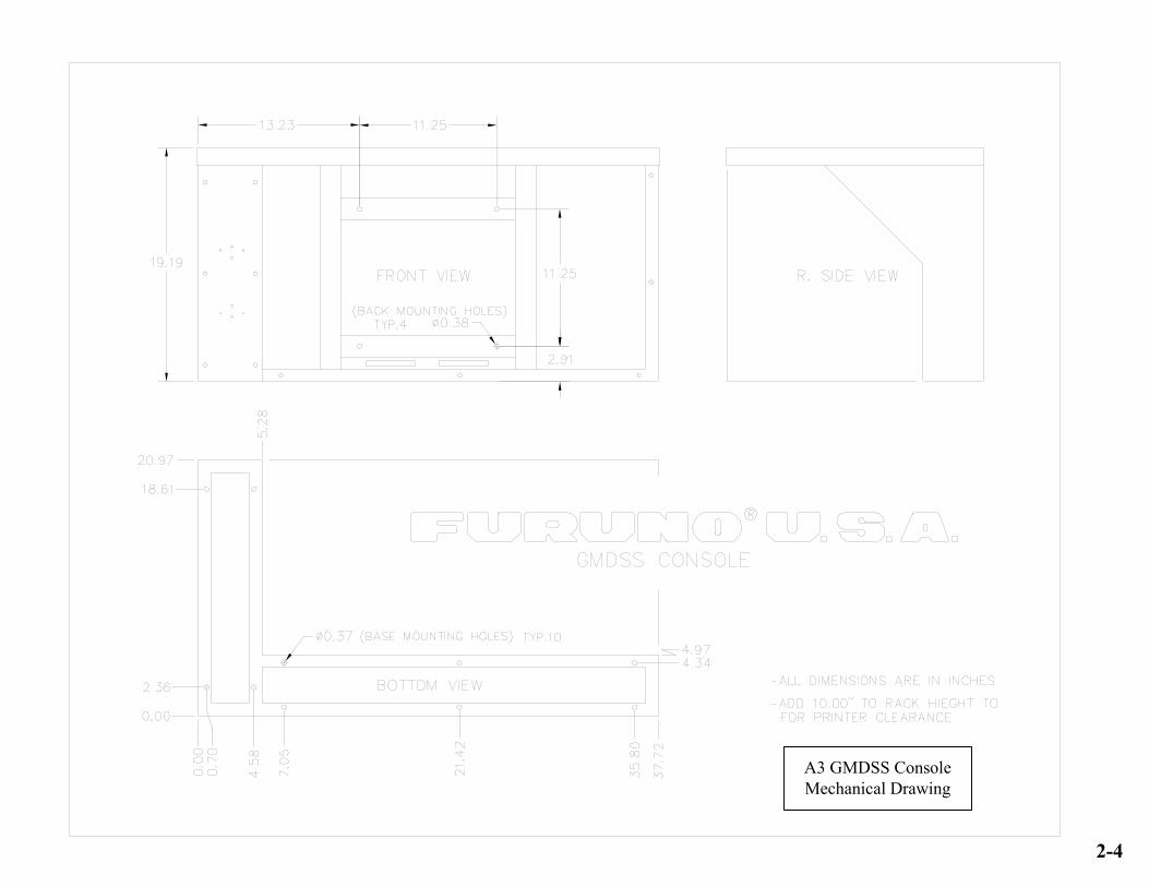
A3 GMDSS ConsoleMechanical Drawing
2-4

3. RC18xx Console Wiring
3-1
3.1 Electrical Connections Refer to RC1815/RC1825 and RC1840 Meter Box Assembly Drawing 3.1.1 Meter Box All power connections to the RC18xx series console are made to the Meter Box. Access to the Meter Box is made by removing four, countersunk phillips, screws
from the bottom and sliding the cover back and down. On the inside of the cover is a mechanical layout of the box, to assist with installation.
3.1.2 Batteries
Connect the battery system using the appropriate wire size to handle the current capacity of the console (Refer to Pg. 3-3, RC18xx Battery Requirements). Batteries => Meter Box Assembly 1) Battery Negative => TB1-1 in the Meter Box Assembly 2) Battery Positive => TB1-2 in the Meter Box Assembly 3.1.3 Battery Charger The Battery Charger, which is Dealer supplied, attaches to TB1 in the Meter Box Assembly. Battery Charger => Meter Box Assembly 1) Negative Output => TB1-3 in the Meter Box Assembly 2) Positive Output => TB1-4 in the Meter Box Assembly 3.1.4 PR-300 Power Supply (RC1840) Determine the AC Input to be used with the PR-300 (Factory setting is for 220 VAC). Using the diagram supplied with the PR-300, open the supply and set the transformer taps for the correct voltage. Reassemble the supply. PR-300 (RC1840) 1) AC IN => AC Input from Ships Mains (100 to 220 VAC) 2) DC IN (Negative) => TB1-5 Meter Box Assembly 3) DC IN (Positive) = > TB1-6 Meter Box Assembly 4) 24V DC OUT (Negative) = > TB1-9 Meter Box Assembly 5) 24V DC OUT (Positive) = > TB1-10 Meter Box Assembly

3. RC18xx Console Wiring
3-2
3.1 Electrical Connections (Continued) Refer to RC1815/RC1825 and RC1840 Meter Box Assembly Drawing 3.1.5 PR-850A Power Supply Determine the AC Input to be used with the PR-850A (Factory setting is for 220 VAC). Using the diagram supplied with the PR-850A, open the supply and set the transformer taps for the correct voltage. Reassemble the supply. PR-850A => Console and Outside Connections PR-850A Front Connections 1) AC IN => AC Input from Ships Mains (100 to 240 VAC) 2) 24 VDC Output => Not Used PR-850A Rear Connections (RC1815 and RC1825) 1) Battery IN (Negative) = > TB1-5 Meter Box Assembly 2) Battery IN (Positive) = > TB1-6 Meter Box Assembly 3) AC Fail (Positive) => TB1-7 Meter Box Assembly 4) AC Fail (Negative) = > TB1-8 Meter Box Assembly 5) 24 VDC OUT (Negative) = > TB1-9 Meter Box Assembly => TB2 FS-1570/ FS-2570 Transceiver 6) 24 VDC OUT (Positive) => TB1-10 Meter Box Assembly => TB1 FS-1570/ FS-2570 Transceiver PR-850A when used with the RC1840 24 VDC OUT (Neg. and Pos.) => To FS-5000 Transceiver. * The FS-5000 requires 60 Amps peak current.* 3.1.6 NMEA/IEC-61162 Connections Refer to Pg. S-6, Felcom 15, IC-315 Junction Box Connections drawing.

RC18xx Battery Requirements
Current / RC1815 RC1825 RC1840Equipment Calculation Amps Amps AmpsPP510 0.4A x 2 = 0.8 0.8 0.8DSC-60 1.0A = 1DP-6 1.6A = 1.6AC Fail Lamp 0.3A = 0.3 0.3 0.3Emer. Lamp 0.3A = 0.3 0.3 0.3Felcom 15 RX 0.9A = 0.9 0.9 0.9Felcom 15 TX 5A/2 = 2.5 2.5 2.5IB-583 0.6A = 0.6 0.6FS-1570 RX 0.8A = 0.8FS-1570 TX 20A/2 = 10FS-2570 RX 1.5A = 1.5FS-2570 TX 35A/2 = 17.5FS-5000 RX 3A = 3FS-5000 TX 60A/2 = 30FM-8800 RX 1.6A x 2 = 3.2 3.2 3.2FM-8800 TX (4.7A/2) x 2 = 4.7 4.7 4.7Amps Per Hour 24.1 32.3 48.3
* Method used for calculation: 1/2 of the current consumption necessary for transmission + the current necessary for reception + current consumption of any additional loads
3-3
4. RC1815/RC1825 Equipment Installations
4-1
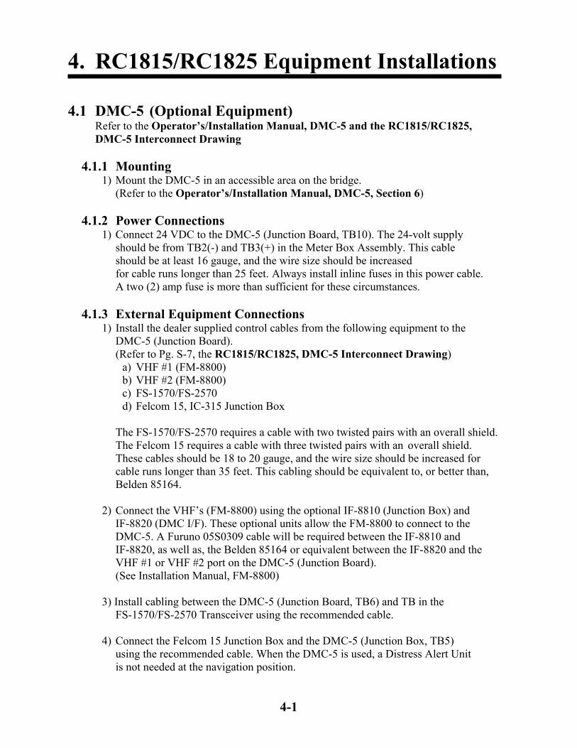
4.1 DMC-5 (Optional Equipment) Refer to the Operator’s/Installation Manual, DMC-5 and the RC1815/RC1825, DMC-5 Interconnect Drawing 4.1.1 Mounting 1) Mount the DMC-5 in an accessible area on the bridge. (Refer to the Operator’s/Installation Manual, DMC-5, Section 6) 4.1.2 Power Connections 1) Connect 24 VDC to the DMC-5 (Junction Board, TB10). The 24-volt supply should be from TB2(-) and TB3(+) in the Meter Box Assembly. This cable should be at least 16 gauge, and the wire size should be increased for cable runs longer than 25 feet. Always install inline fuses in this power cable. A two (2) amp fuse is more than sufficient for these circumstances. 4.1.3 External Equipment Connections 1) Install the dealer supplied control cables from the following equipment to the DMC-5 (Junction Board). (Refer to Pg. S-7, the RC1815/RC1825, DMC-5 Interconnect Drawing) a) VHF #1 (FM-8800) b) VHF #2 (FM-8800) c) FS-1570/FS-2570 d) Felcom 15, IC-315 Junction Box The FS-1570/FS-2570 requires a cable with two twisted pairs with an overall shield. The Felcom 15 requires a cable with three twisted pairs with an overall shield. These cables should be 18 to 20 gauge, and the wire size should be increased for cable runs longer than 35 feet. This cabling should be equivalent to, or better than, Belden 85164. 2) Connect the VHF’s (FM-8800) using the optional IF-8810 (Junction Box) and IF-8820 (DMC I/F). These optional units allow the FM-8800 to connect to the DMC-5. A Furuno 05S0309 cable will be required between the IF-8810 and IF-8820, as well as, the Belden 85164 or equivalent between the IF-8820 and the VHF #1 or VHF #2 port on the DMC-5 (Junction Board). (See Installation Manual, FM-8800) 3) Install cabling between the DMC-5 (Junction Board, TB6) and TB in the FS-1570/FS-2570 Transceiver using the recommended cable. 4) Connect the Felcom 15 Junction Box and the DMC-5 (Junction Box, TB5)
using the recommended cable. When the DMC-5 is used, a Distress Alert Unit is not needed at the navigation position.
4. RC1815/RC1825 Equipment Installations
4-2
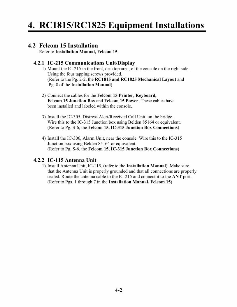
4.2 Felcom 15 Installation Refer to Installation Manual, Felcom 15 4.2.1 IC-215 Communications Unit/Display 1) Mount the IC-215 in the front, desktop area, of the console on the right side. Using the four tapping screws provided. (Refer to the Pg. 2-2, the RC1815 and RC1825 Mechanical Layout and Pg. 8 of the Installation Manual) 2) Connect the cables for the Felcom 15 Printer, Keyboard, Felcom 15 Junction Box and Felcom 15 Power. These cables have been installed and labeled within the console. 3) Install the IC-305, Distress Alert/Received Call Unit, on the bridge. Wire this to the IC-315 Junction box using Belden 85164 or equivalent. (Refer to Pg. S-6, the Felcom 15, IC-315 Junction Box Connections) 4) Install the IC-306, Alarm Unit, near the console. Wire this to the IC-315 Junction box using Belden 85164 or equivalent. (Refer to Pg. S-6, the Felcom 15, IC-315 Junction Box Connections) 4.2.2 IC-115 Antenna Unit 1) Install Antenna Unit, IC-115, (refer to the Installation Manual). Make sure
that the Antenna Unit is properly grounded and that all connections are properly sealed. Route the antenna cable to the IC-215 and connect it to the ANT port.
(Refer to Pgs. 1 through 7 in the Installation Manual, Felcom 15)

4. RC1815/RC1825 Equipment Installations
4-3
4.3 FM-8800 Installation Refer to Installation Manual, FM-8800 4.3.1 Transceiver There are two FM-8800’s in the standard console configurations. One unit is mounted in the console, and will not require installation of a NMEA cable or
power cable. The handset and hanger, for the console mounted FM-8800, must be mounted in a location that is convenient for the user. The second unit is remotely mounted on the bridge, and will require the installation procedure listed below.
1) Mount the transceiver bracket. (Refer to Pg. 1-3 of the Installation Manual)
2) Screw the knob bolts with washers into the transceiver unit. 3) Set the transceiver unit into the mounting bracket and tighten the knob bolts. 4) Install the supplied Power Cable (000-151-711), from the transceiver, to TB2(-) and TB3(+) in the Meter Box Assembly.
This power cable is protected by inline fuses (15A), any addition cable added, must also be protected.
5) Make a NMEA cable using the supplied connector (000-145-424) and shell (000-145-423). Connect from the NMEA/REMOTE port on the transceiver to the IC-315 Junction Box. Use Belden 8302 or equivalent cable. (Refer to Pg. S-6, the Felcom 15, IC-315 Junction Box Connections) 6) Attach a ground strap from the transceiver ground stud to the ship’s hull or ground system. 7) Mount the handset hanger and connect to the HANDSET port on the front of the transceiver. 4.3.2 Antennas Two standard marine VHF antennas are necessary for both FM-8800’s. One antenna is the main TX/RX antenna while the second is the Channel 70 RX antenna for the DSC receiver. 1) Mount both VHF antennas. Make sure that they are separated vertically to prevent the TX antenna from interfering with the channel 70 RX antenna. 2) Install the cables and connect the transmit antenna to the ANT port and the receive antenna to the CH 70 ANT port on the transceiver.

4. RC1815/RC1825 Equipment Installations
4-4
4.4 FS-1570/FS-2570 Installation Refer to Installation Manual, FS-1570 (150W) / FS-2570 (250W) 4.4.1 Control Unit 1) The FS-2570C (Control Unit) and HS2001 (Handset) have been mounted and wired into the console. 4.4.2 Transceiver Unit
1) The Transceiver is designed for bulkhead mounting using six tapping screws or bolts. Select a location that can support the weight of the unit, (FS-1570: 25 lbs., FS-2570: 31 lbs.), under the operating conditions encountered onboard the ship. If necessary, reinforce the mounting location. 2) Connect the 24 VDC, Rear Connections: PR850A, to TB1(+) and TB2(-) of the
transceiver, through a set of inline breakers or fuses. When installing the power cable in the transceiver, use a razor knife to cut an opening in the grommet.
The FS-1570, which draws 20 amps, will require an 8-gauge wire for up to 40 feet separation from the PR850A power supply. The FS-2570, which draws 35 amps, will require a 6-gauge wire for up to 40 feet separation from the PR850A power supply. 3) Connect the cable Controller 1, connected to the FS-2570C, to the transceiver port Controller 1.
4.4.3 Antenna 1) The antenna is to be provided by the Dealer. This antenna should be 7 to 30 meters in length and be mounted as clear of obstructions as possible. When considering the mounting location of the antenna, be sure to allow space for mounting the antenna coupler. 4.4.4 Antenna Coupler AT-1560-15 or AT-1560-25 1) Mount the antenna coupler as close to the antenna as possible. The provided coupler can be mounted horizontally or vertically depending on the location. (Refer to Pgs. 2-1 through 2-3 of the Installation Manual) 2) Connect the antenna wire from the antenna to the insulator at the top of the coupler. Keeping the length as short as possible. 3) Fasten the supplied ground strap to the connection provided at the base of the antenna coupler. Make certain this connection is brazed or welded to the ship’s hull or ground system. The exposed ground strap should be painted or coated with a material to prevent rust.
4. RC1815/RC1825 Equipment Installations
4-5
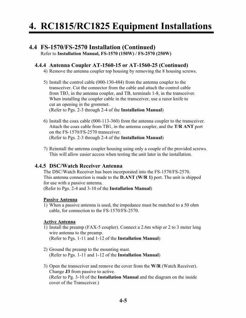
4.4 FS-1570/FS-2570 Installation (Continued) Refer to Installation Manual, FS-1570 (150W) / FS-2570 (250W) 4.4.4 Antenna Coupler AT-1560-15 or AT-1560-25 (Continued) 4) Remove the antenna coupler top housing by removing the 8 housing screws. 5) Install the control cable (000-130-484) from the antenna coupler to the transceiver. Cut the connector from the cable and attach the control cable from TB3, in the antenna coupler, and TB, terminals 1-8, in the transceiver.
When installing the coupler cable in the transceiver, use a razor knife to cut an opening in the grommet.
(Refer to Pgs. 2-3 through 2-4 of the Installation Manual) 6) Install the coax cable (000-113-360) from the antenna coupler to the transceiver. Attach the coax cable from TB1, in the antenna coupler, and the T/R ANT port on the FS-1570/FS-2570 transceiver. (Refer to Pgs. 2-3 through 2-4 of the Installation Manual) 7) Reinstall the antenna coupler housing using only a couple of the provided screws. This will allow easier access when testing the unit later in the installation. 4.4.5 DSC/Watch Receiver Antenna The DSC/Watch Receiver has been incorporated into the FS-1570/FS-2570.
This antenna connection is made to the D.ANT (W/R 1) port. The unit is shipped for use with a passive antenna. (Refer to Pgs. 2-4 and 3-10 of the Installation Manual)
Passive Antenna 1) When a passive antenna is used, the impedance must be matched to a 50 ohm cable, for connection to the FS-1570/FS-2570. Active Antenna 1) Install the preamp (FAX-5 coupler). Connect a 2.6m whip or 2 to 3 meter long
wire antenna to the preamp. (Refer to Pgs. 1-11 and 1-12 of the Installation Manual)
2) Ground the preamp to the mounting mast. (Refer to Pgs. 1-11 and 1-12 of the Installation Manual) 3) Open the transceiver and remove the cover from the W/R (Watch Receiver). Change J3 from passive to active.
(Refer to Pg. 3-10 of the Installation Manual and the diagram on the inside cover of the Transceiver.)

4. RC1815/RC1825 Equipment Installations
4-6
4.4 FS-1570/FS-2570 Installation (Continued) Refer to Installation Manual, FS-1570 (150W) / FS-2570 (250W) 4.4.5 DSC/Watch Receiver Antenna (Continued) 4) Reassemble the transceiver. 4.4.6 NMEA/IEC-61162 Connection 1) Install a cable, Belden 8302 or equivalent, from the Felcom 15 Junction Box to the FS-1570/FS-2570 transceiver. Connect this cable per the notations on Pg. S-6, the Felcom 15, IC-315 Junction Box Connections. (Refer to Pg. 2-2, the RC1815 and RC1825 Mechanical Layout for the location of the IC-315 Junction Box)

4. RC1815/RC1825 Equipment Installations
4-7
4.5 IB-583 NBDP Terminal Refer to Installation Manual, FS-1570 (150W) / FS-2570 (250W) 4.5.1 Mounting 1) Mount the IB-583 in the front, desktop area, of the console on the left side. Using the four tapping screws provided. (Refer to Pg. 2-2, the RC1815 and RC1825 Mechanical Layout and Pg. 4-4 of the Installation Manual) 4.5.2 Power Connections 1) Connect power cable, IB-583 Power, to the IB-583 display. 4.5.3 Additional Connections 1) Connect the printer cable, IB-583 Printer, to the printer port. 2) Connect control cable, IB-583 DTE, to the DTE port. 3) Connect the keyboard to the Keyboard port on the IB-583.

5. RC1815/RC1825 Equipment Setup
5-1
5.1 General
• When the installations are completed, proceed through the setup procedures.
• The MMSI number and INMARSAT number will be needed to complete the setup and testing procedures.
5.1.1 Powering Up Equipment 1) Power on the PR850A. Power on the battery charger.
2) Install the printer paper and turn on the printers. 3) Turn on all of the following equipment before starting the setup procedures: a) FS-1570/FS-2570 (RC1815 and RC1825) b) IB-583 c) Felcom 15 d) FM-8800’s (VHF1 and VHF2) e) DMC-5 (optional) 4) Each piece of equipment goes through a self-test on start up and will show any errors discovered during this process. Record any errors for future reference.
5.1.2 E Meter
1) The E Meter should be displaying the battery voltage. Press the [SEL] key and the battery charge current should be displayed.
2) The battery Amp/Hour rating is set at the factory for 200 Amp/Hour.
If your batteries are a different rating, this setting must be changed to match your batteries. The Amp/Hour settings are in increments of 20 Amp/Hours. Example: A setting of 200 would be sufficient for 210 Amp/Hour. Never set the rating higher than the rating of the batteries.
(Refer to Pg. 21 of the E Meter Owners Manual)

5. RC1815/RC1825 Equipment Setup
5-2
5.2 DMC-5 (Optional Equipment) Refer to the Operator’s/Installation Manual, DMC-5 5.2.1 General
The setup and testing of the DMC-5 should be completed last. This unit expects all equipment, in the console, to already be operational.
1) After powering up the DMC-5 for the first time the screen should be as shown above. 2) Press the [SET UP] key, then the 0 key four times. 3) Then press the [ENT] key. 5.2.2 VHF Input
1) Press the [SET UP] key, then the 4 [VHF] key. 2) Press the [SELECT] to highlight No.1, then press the [ENT] key. 5.2.3 MF/HF Input
1) The display should appear as shown above, if it does continue to step 2. If the Pos: still shows NG, check the DMC-5 wiring and programming of VHF No.1, which should be mounted in the console.
2) Press the [SET UP] key, then the 5 [MF/HF] key.
3) Press the [SELECT] key to highlight J3E, then press the [ENT] key.
*Watch* Pos: NG 00:00 Manual input ? [ SET UP ] Key
*Watch* Pos: manu 00:00
*Watch* Pos: auto 00:00 VHF

5. RC1815/RC1825 Equipment Setup
5-3
5.2 DMC-5 (Continued) Refer to the Operator’s/Installation Manual, DMC-5 5.2.4 SES Input (INMARSAT C Terminal)
1) The display should appear as shown above, if it does continue to step 2. If not record the error and check the appropriate equipment.
2) Press the [SET UP] key, then the 6 [SES] key.
3) Press the [SELECT] key three times to highlight SES (EGC), then press the [ENT] key.
5.2.5 Time and Date
1) The display should appear as shown above, if it does continue to step 2. If not record the error and check the appropriate equipment.
2) Press the [SELECT] key, then the [ENT] key. 3) Enter the Year and press the [SELECT] key. 4) Enter the Date, month and day, and press the [SELECT] key.
5) Enter the UTC Time, and press the [SELECT] key.
6) Then the [ENT] key.
7) The display should appear as shown above, if it does the setup is complete. If not record the error and check the appropriate equipment.
*Watch* Pos: auto 00:00 VHF MF/HF
*Watch* Pos: auto 00:00 VHF MF/HF SES(EGC)
*Watch* Pos: auto 21:30 VHF MF/HF SES(EGC)

5. RC1815/RC1825 Equipment Setup
5-4
5.3 Felcom 15 Refer to the Installation Manual, Felcom 15 5.3.1 General 1) Insert a good, formatted, floppy disk into the Terminal. 2) Power up the Felcom 15, the status screen should show OK indications and the GPS should indicate 3D. 5.3.2 IMN Input
(Refer to Pg. 19 of the Installation Manual, Felcom 15) 1) Press the [F8] key, using the down arrow key, highlight IMN and then press the [Enter] key.
2) Type in the IMN and press the [Enter] key.
3) Press the [Esc] key. The screen will now prompt Update. Select Yes and press the [Enter] key. 4) Press the [Esc] key until you return to the status screen. 5.3.3 External Equipment
(Refer to Pg. 20 of the Installation Manual, Felcom 15)
The Felcom 15 has been programmed for use with the following remote boxes: 1) IC-305 Distress Alert Unit 2) IC-306 Alarm Unit Unless a DMC-5 or additional boxes are added no changes are necessary. To change these settings, refer to Pg. 4 of the Dealers Manual.

5. RC1815/RC1825 Equipment Setup
5-5
INTL
Hi 16DSC NOT USABLELAT : 35 10’ NLON : 135 11’ E AUTO
Rx
10 : 10 UTC
INTL
Hi 16AUTO ACK WATCH CH 70LAT : 35 10’ NLON : 135 11’ E AUTO
Rx
10 : 10 UTC
5.4 FM-8800 Refer to the Installation Manual, FM-8800 5.4.1 General
This setup must be performed on both FM-8800’s.
1) Power up the unit. 2) The main display will show Longitude/Latitude and UTC time if the NMEA connection is active. This NMEA information is supplied by the Felcom 15. If it is not displayed check the NMEA cables and connections. (Refer to Pg. S-6, the Felcom 15, IC-315 Junction Box Connections) MMSI Registered MMSI Not Registered 5.4.2 MMSI and System Settings 1) These settings should be completed by an authorized Furuno Agent or Dealer. See pages 5-7 of the A3 GMDSS Console Dealers Manual.

5. RC1815/RC1825 Equipment Setup
5-6
5.5 FS-1570/FS-2570 Refer to the Installation Manual, FS-1570 (150W) / FS-2570 (250W) 5.5.1 General 1) Power up the unit and press the [1/RT] key. 2) Press the [3/TEST]. Allow the test to complete and verify all checks are OK. 5.5.2 RT Operation 1) On each band, verify that the antenna automatically tunes when the [LOG/TUNE] key is pressed. 2) If all tests are OK, proceed on to the next section. If the tune fails, verify the antenna, grounding system and the coupler connections. 5.5.3 MMSI
1) To set the MMSI, refer to the Dealers Manual, Pg. 4.
5.5.4 Manual 2182 kHz Tuning Preset 1) Press the [1/RT/2182] key for 2 seconds.
2) Press the [LOG/TUNE] key, TUNING: OK will appear when the tuning is complete. 3) Open the coupler and record the status of the LED’s CR1-CR22.
(Refer to Pgs. 3-1 and 3-2 of the Installation Manual, FS-1570 (150W) / FS-2570 (250W)) 4) Set S1 to Manual. Set switches S4, S5 and S6 to match the LED’s recorded in step 3. 5) Set S1 to AUTO. The LED’s should stay the same as step 4. 6) Secure the antenna coupler cover.

5. RC1815/RC1825 Equipment Setup
5-7
5.6 IB-583 NBDP Terminal Refer to the Installation Manual, FS-1570 (150W) / FS-2570 (250W) 5.6.1 General 1) Power up the unit. 2) Press the [F6] key, to enter the System menu. 3) Use the arrow keys to select Change. 4) Use the down arrow key to highlight Self Test. 5) Verify all test are OK and that the self-test prints out. 5.6.2 ID Codes 1) Press the [F5] key, to enter the Station menu. 2) Press the key to select the ID to be entered: 6: Group ID Entry (4/5 digit) 7: Group ID Entry (9 digit) 8: Select ID Entry (4/5 digit) 9: Select ID Entry (9 digit)
(If an incorrect entry is made, refer to the Dealers Manual, Pg. 9) 5.6.3 Answerback Code 1) Press the [F5] key, to enter the Station menu. 2) Press the [5] key to select Answerback Code Entry. 3) Enter the Answerback code in the following format: Example: 123456789 FURU X This format is the 9 digit MMSI, 4 letters and X.
(If an incorrect entry is made, refer to the Dealers Manual, Pg. 9)

6. RC1840 Equipment Installations
6-1
6.1 DMC-5 (Optional Equipment)
Refer to the Operator’s/Installation Manual, DMC-5 and the RC1840, DMC-5 Interconnect Drawing
6.1.1 Mounting 1) Mount the DMC-5 in an accessible area on the bridge. (Refer to the Operator’s/Installation Manual, DMC-5, Section 6) 6.1.2 Power Connections 1) Connect 24 VDC to the DMC-5 (Junction Board, TB10). The 24-volt supply should be from TB2(-) and TB3(+) in the Meter Box Assembly. This cable should be at least 16 gauge, and the wire size should be increased for cable runs longer than 25 feet. Always install inline fuses in this power cable. A two (2) amp fuse is more than sufficient for these circumstances. 6.1.3 External Equipment Connections 1) Install the dealer supplied control cables from the following equipment to the DMC-5 (Junction Board). (Refer to Pg. S-8, the RC1840, DMC-5 Interconnect Drawing) a) VHF #1 (FM-8800) b) VHF #2 (FM-8800) c) DSC-60 d) Felcom 15, IC-315 Junction Box The DSC-60 requires a cable with two twisted pairs with an overall shield. The Felcom 15 requires a cable with three twisted pairs with an overall shield. These cables should be 18 to 20 gauge, and the wire size should be increased for cable runs longer than 35 feet. This cabling should be equivalent to, or better than, Belden 85164. 2) Connect the VHF’s (FM-8800) using the optional IF-8810 (Junction Box) and IF-8820 (DMC I/F). These optional units allow the FM-8800 to connect to the DMC-5. A Furuno 05S0309 cable will be required between the IF-8810 and IF-8820, as well as, the Belden 85164 or equivalent between the IF-8820 and the VHF #1 or VHF #2 port on the DMC-5 (Junction Board). (See Installation Manual, FM-8800) 3) Install cabling between the DMC-5 (Junction Board, TB6) and the DSC-60, (J4) DMC port. Use the supplied connector (000-116-185) and the recommended
cable. 4) Connect the Felcom 15 Junction Box and the DMC-5 (Junction Box, TB5)
using the recommended cable. When the DMC-5 is used, a Distress Alert Unit is not needed at the navigation position.

6. RC1840 Equipment Installations
6-2
6.2 DP-6 NBDP Terminal Refer to the Installation Manual, DP-6 6.2.1 Main Unit 1) Mount the DP-6 Main Unit. Route the provided cables from the console to the Main Unit. The following cables are provided in the console for the Main Unit (Refer to Pg. 9 of the Installation Manual, NBDP Terminal DP-6) a) Power cable b) NMEA cable c) Remote A cable d) Remote B cable e) Terminal cable (This is a DB-9M to DB-9F and is provided in the DP-6 Terminal, IB581/6, box.)
2) Attach the provided ground wire between the rear of the Main Unit and the ship’s ground system. 6.2.2 Terminal Unit 1) Install the DP-6 Terminal hanger bracket on the left side of the console.
2) Attach the provided cables to the Terminal. (Refer to Pg. 9 of the Installation Manual, NBDP Terminal DP-6) a) Power Cable b) Printer Cable c) Terminal Cable-COM1 (This is the other end of the DB-9M to DB-9F connected to the Main Unit.) d) Keyboard 3) Attach the provided ground wire between the rear of the Terminal and the ship’s ground system. 4) Set the Terminal into the hanger bracket and secure using the Terminal knobs. 5) Mount the keyboard with the provided velcro fasteners.

6. RC1840 Equipment Installations
6-3
6.3 DSC-60 DSC/Watch Receiver Refer to the Installation Manual, DSC-60 The DSC-60 DSC/Watch Receiver has been mounted and wired into the console.
Only the antenna needs to be installed. A label is attached to the DSC-60 front panel to show if the unit is setup for an active or passive antenna. This antenna connection is made to the D.ANT port.
(Refer to Pg. 7 of the Installation Manual for the correct antenna port location.) 6.3.1 Passive Antenna 1) When a passive antenna is used, the impedance must be matched to the 50 ohm cable, for connection to the DSC-60. 2) If necessary, disassemble the DSC-60 and change the jumper on the RCVR board from active to passive. (Refer to Pg. 20, Preamp Settings, of the Installation Manual) 3) When reinstalling the DSC-60 in the console, be sure to attach the cables to the correct ports. (Refer to Pg. 7 of the Installation Manual) 6.3.2 Active Antenna 1) Install the preamp (FAX-5 coupler). Connect a 2.6m whip or 2 to 3 meter long wire to the preamp. (Refer to Pgs. 3 and 4, Preamp Unit, of the Installation Manual) 2) Ground the preamp to the mounting mast. (Refer to Pg. 4 of the Installation Manual) 3) If necessary disassemble the DSC-60 and change the jumper on the RCVR board from passive to active. (Refer to Pg. 20, Preamp Settings, of the Installation Manual) 4) When reinstalling the DSC-60 in the console, be sure to attach the cables to the correct ports. (Refer to Pg. 7 of the Installation Manual)

6. RC1840 Equipment Installations
6-4
6.4 Felcom 15 Installation Refer to Installation Manual, Felcom 15 6.4.1 IC-215 Communications Unit/Display 1) Mount the IC-215 in the front, desktop area, of the console on the right side. Using the four tapping screws provided. (Refer to Pg. 2-3, the RC1840 Mechanical Layout and Pg. 8 of the Installation Manual) 2) Connect the cables for the Felcom 15 Printer, Keyboard, Felcom 15 Junction Box and Felcom 15 Power. These cables have been installed and labeled within the console. 3) Install the IC-305, Distress Alert/Received Call Unit, on the bridge. Wire this to the IC-315 Junction box using Belden 85164 or equivalent. (Refer to Pg. S-6, the Felcom 15, IC-315 Junction Box Connections)
4) Install the IC-306, Alarm Unit, near the console. Wire this to the IC-315 Junction box using Belden 85164 or equivalent.
(Refer to Pg. S-6, the Felcom 15, IC-315 Junction Box Connections) 6.4.2 IC-115 Antenna Unit 1) Install Antenna Unit, IC-115, (refer to the Installation Manual). Make sure
that the Antenna Unit is properly grounded and that all connections are properly sealed. Route the antenna cable to the IC-215 and connect it to the ANT port.
(Refer to Pgs. 1 through 7 in the Installation Manual, Felcom 15)

6. RC1840 Equipment Installations
6-5
6.5 FM-8800 Installation Refer to Installation Manual, FM-8800 6.5.1 Transceiver There are two FM-8800’s in the standard console configurations. One unit is mounted in the console, and will not require installation of a NMEA cable or
power cable. The handset and hanger, for the console mounted FM-8800, must be mounted in a location that is convenient for the user. The second unit is remotely mounted on the bridge, and will require the installation procedure listed below.
1) Mount the transceiver bracket. (Refer to Pg. 1-3 of the Installation Manual)
2) Screw the knob bolts with washers into the transceiver unit. 3) Set the transceiver unit into the mounting bracket and tighten the knob bolts. 4) Install the supplied Power Cable (000-151-711), from the transceiver, to TB2(-) and TB3(+) in the Meter Box Assembly.
This power cable is protected by inline fuses (15A), any addition cable added, must also be protected.
5) Make a NMEA cable using the supplied connector (000-145-424) and shell (000-145-423). Connect from the NMEA/REMOTE port on the transceiver to the IC-315 Junction Box. Use Belden 8302 or equivalent cable. (Refer to Pg. S-6, the Felcom 15, IC-315 Junction Box Connections) 6) Attach a ground strap from the transceiver ground stud to the ship’s hull or ground system. 7) Mount the handset hanger and connect to the HANDSET port on the front of the transceiver. 6.5.2 Antennas Two standard marine VHF antennas are necessary for both FM-8800’s. One antenna is the main TX/RX antenna while the second is the Channel 70 RX antenna for the DSC receiver. 1) Mount both VHF antennas. Make sure that they are separated vertically to prevent the TX antenna from interfering with the channel 70 RX antenna. 2) Install the cables and connect the transmit antenna to the ANT port and the receive antenna to the CH 70 ANT port on the transceiver.

6. RC1840 Equipment Installations
6-6
6.6 FS-5000 Refer to the Operator’s/Installation Manual, FS-5000 6.6.1 Transceiver Unit 1) Mount the Transceiver Unit. Leave at least 25mm space behind the transceiver.
This will allow access for service. (Refer to Pgs. 3-10 and 3-11 of the Installation Manual)
2) Remove the front cover. The cables should feed into the transceiver by way of the cable entry located on the bottom of the transceiver.
3) Connect the 24 VDC, Rear Connections: PR850A, to TB1(+) and TB2(-) of the transceiver, through a set of inline breakers or fuses. The FS-5000, which draws 60 amps, will require a 4-gauge wire for up to 40 feet separation from the PR850A power supply.
(Refer to Pg. 3-12a of the Installation Manual and Pg. S-5, the Meter Box Assembly RC1840) 4) Loosen the two screws holding the cable clamp. Install a 50mm width copper strap between the cable holder and the ship’s hull or ground system. (Refer to Pg. 3-13 of the Installation Manual) 5) Leave the transceiver covers open. There are more connections to be made as the installation progresses. 6.6.2 Control Unit 1) Mount the Control Unit as close as possible to the console. Use of the optional
Trunnion Mount (005-931-760) is recommended. (Refer to Pgs. 3-6, 3-7 and AP2-1 of the Installation Manual)
2) Disassemble the control unit. 3) Attach one end of the control cable (000-106-043) to TB1 (MAIN) in the
control unit. The free end will be connected to the transceiver later in the installation.
4) Attach the separate RCC-15D-206 supplied with the console from DP-6 Remote A to REM2 port in the control unit. 5) Attach the flying leads, from the RCC-15D-206 cable connected to the DSC-60 (RT), to the REM1 port in the control unit. (Refer to Pg. S-3, the RC1540 Detailed Interconnect Drawing and Pg. S-2 of the Installation Manual)

6. RC1840 Equipment Installations
6-7
6.6 FS-5000 (Continued) Refer to the Operator’s/Installation Manual, FS-5000 6.6.2 Control Unit (Continued) 6) Mount the handset hanger and connect to the HANDSET port on the control unit. 7) Reassemble the control unit and attach to the mounting bracket. 6.6.3 Antenna 1) The antenna is to be provided by the Dealer. This antenna should be 7 to 30 meters in length and be mounted as clear of obstructions as possible. When considering the mounting location of the antenna, be sure to allow space for mounting the antenna coupler. 6.6.4 Antenna Coupler (AT-5000) 1) Mount the antenna coupler as close to the antenna as possible. The provided coupler can be mounted horizontally or vertically depending on the location. (Refer to Pgs. 3-14 through 3-18 of the Installation Manual) 2) Connect the antenna wire from the antenna to the insulator at the top of the coupler. Keeping the length as short as possible. 3) Fasten the supplied ground strap to the connection provided at the base of the antenna coupler. Make certain this connection is brazed or welded to the ship’s hull or ground system. The exposed ground strap should be painted or coated with a material to prevent rust. 4) Remove antenna coupler top housing by removing the 12 housing screws. 5) Install the supplied control cable (000-106-043) from the antenna coupler to the transceiver. Attach to TB-3 on the Coupler Board and TB-8 on the Transceiver Interface Board. (Refer to Pgs. 3-13 and 3-17 of the Installation Manual) 6) Install two RF cables (RG8 or equivalent, not supplied) from the antenna coupler to the transceiver unit. The first cable is the receive cable and will connect to the RX ANT port in the transceiver and to TB1 on the BK RELAY in the antenna coupler. The second cable is the transmit cable and will connect to the TX ANT port in the transceiver and to TB1, TX ANT on the antenna coupler board. 7) Reinstall antenna coupler housing using only a couple of the provided screws. This will allow easier access when testing the unit later in the install.
Fasten the cable clamps in the transceiver, but do not install the covers until testing is completed.

7. RC1840 Equipment Setup
7-1
7.1 General
• When the installations are completed, proceed through the setup procedures.
• The MMSI number and INMARSAT number will be needed to complete the setup and testing procedures.
7.1.1 Powering Up Equipment 1) Power on the PR850A and PR300. Power on the battery charger.
2) Install the printer paper and turn on the printers. 3) Turn on all of the following equipment before starting the setup procedures: a) FS-5000 b) DSC-60 c) DP-6 Main and Terminal Units d) Felcom 15 e) FM-8800’s (VHF1 and VHF2) f) DMC-5 (optional) 4) Each piece of equipment goes through a self-test on start up and will show any errors discovered during this process. Record any errors for future reference.
7.1.2 E Meter
1) The E Meter should be displaying the battery voltage. Press the [SEL] key and the battery charge current should be displayed.
2) The battery Amp/Hour rating is set at the factory for 200 Amp/Hour.
If your batteries are a different rating, this setting must be changed to match your batteries. The Amp/Hour settings are in increments of 20 Amp/Hours. Example: A setting of 200 would be sufficient for 210 Amp/Hour. Never set the rating higher than the rating of the batteries.
(Refer to Pg. 21 of the E Meter Owners Manual)

7. RC1840 Equipment Setup
7-2
7.2 DMC-5 (Optional Equipment) Refer to the Operator’s/Installation Manual, DMC-5 7.2.1 General
The setup and testing of the DMC-5 should be completed last. This unit expects all equipment, in the console, to already be operational.
1) After powering up the DMC-5 for the first time the screen should be as shown above. 2) Press the [SET UP] key, then the 0 key four times. 3) Then press the [ENT] key. 7.2.2 VHF Input
1) Press the [SET UP] key, then the 4 [VHF] key. 2) Press the [SELECT] to highlight No.1, then press the [ENT] key. 7.2.3 MF/HF Input
1) The display should appear as shown above, if it does continue to step 2. If the Pos: still shows NG, check the DMC-5 wiring and programming of VHF No.1, which should be mounted in the console.
2) Press the [SET UP] key, then the 5 [MF/HF] key.
3) Press the [SELECT] key to highlight J3E, then press the [ENT] key.
*Watch* Pos: NG 00:00 Manual input ? [ SET UP ] Key
*Watch* Pos: manu 00:00
*Watch* Pos: auto 00:00 VHF

7. RC1840 Equipment Setup
7-3
7.2 DMC-5 (Continued) Refer to the Operator’s/Installation Manual, DMC-5) 7.2.4 SES Input (INMARSAT C Terminal)
1) The display should appear as shown above, if it does continue to step 2. If not record the error and check the appropriate equipment.
2) Press the [SET UP] key, then the 6 [SES] key.
3) Press the [SELECT] key three times to highlight SES (EGC), then press the [ENT] key.
7.2.5 Time and Date
1) The display should appear as shown above, if it does continue to step 2. If not record the error and check the appropriate equipment.
2) Press the [SELECT] key, then the [ENT] key. 3) Enter the Year and press the [SELECT] key. 4) Enter the Date, month and day, and press the [SELECT] key.
5) Enter the UTC Time, and press the [SELECT] key.
6) Then the [ENT] key.
7) The display should appear as shown above, if it does the setup is complete. If not record the error and check the appropriate equipment.
*Watch* Pos: auto 00:00 VHF MF/HF
*Watch* Pos: auto 00:00 VHF MF/HF SES(EGC)
*Watch* Pos: auto 21:30 VHF MF/HF SES(EGC)
7. RC1840 Equipment Setup
7-4
7.3 DP-6 NBDP Terminal Refer to the Installation Manual, DP-6 7.3.1 General 1) Power up the Terminal and main Units. 2) Press the [F6] key, to enter the System menu. 3) Use the arrow keys to select Change. 4) Use the down arrow key to highlight Self Test. 5) Verify all test are OK and that the self-test prints out. 7.3.2 ID Codes 1) Press the [F5] key, to enter the Station menu. 2) Press the key to select the ID to be entered: 6: Group ID Entry (4/5 digit) 7: Group ID Entry (9 digit) 8: Select ID Entry (4/5 digit) 9: Select ID Entry (9 digit)
(If an incorrect entry is made, refer to the Dealers Manual, Pg. 1) 7.3.3 Answerback Code 1) Press the [F5] key, to enter the Station menu. 2) Press the [5] key to select Answerback Code Entry. 3) Enter the Answerback code in the following format: Example: 123456789 FURU X This format is the 9 digit MMSI, 4 letters and X.
(If an incorrect entry is made, refer to the Dealers Manual, Pg. 1)

7. RC1840 Equipment Setup
7-5
7.4 DSC-60 DSC/Watch Receiver Refer to the Installation Manual, DSC-60 7.4.1 General 1) Power up the unit. 2) Press the [3/TEST] key, to start the self-test. 3) The test will run automatically and print the results. 4) Verify all test are OK and press the [CANCEL] key to return to normal operation. 7.4.2 MMSI
1) To set the MMSI, refer to the Dealers Manual, Pg. 2.

7. RC1840 Equipment Setup
7-6
7.5 Felcom 15 Refer to the Installation Manual, Felcom 15 7.5.1 General 1) Insert a good, formatted, floppy disk into the Terminal. 2) Power up the Felcom 15, the status screen should show OK indications and the GPS should indicate 3D. 7.5.2 IMN Input
(Refer to Pg. 19 of the Installation Manual, Felcom 15)
1) Press the [F8] key, using the down arrow key, highlight IMN and then press the [Enter] key.
2) Type in the IMN and press the [Enter] key. 3) Press the [Esc] key. The screen will now prompt Update. Select Yes and press the [Enter] key. 4) Press the [Esc] key until you return to the status screen. 7.5.3 External Equipment
(Refer to Pg. 20 of the Installation Manual, Felcom 15)
The Felcom 15 has been programmed for use with the following remote boxes: 1) IC-305 Distress Alert Unit 2) IC-306 Alarm Unit Unless a DMC-5 or additional boxes are added no changes are necessary. To change these settings, refer to Pg. 4 of the Dealers Manual.

7. RC1840 Equipment Setup
7-7
INTL
Hi 16DSC NOT USABLELAT : 35 10’ NLON : 135 11’ E AUTO
Rx
10 : 10 UTC
INTL
Hi 16AUTO ACK WATCH CH 70LAT : 35 10’ NLON : 135 11’ E AUTO
Rx
10 : 10 UTC
7.6 FM-8800 Refer to the Installation Manual, FM-8800 7.6.1 General
This setup must be performed on both FM-8800’s.
1) Power up the unit. 2) The main display will show Longitude/Latitude and UTC time if the NMEA connection is active. This NMEA information is supplied by the Felcom 15. If it is not displayed check the NMEA cables and connections. (Refer to Pg. S-6, the Felcom 15, IC-315 Junction Box Connections) MMSI Registered MMSI Not Registered 7.6.2 MMSI and System Settings 1) These settings should be completed by an authorized Furuno Agent or Dealer. See pages 5-7 of the A3 GMDSS Console Dealers Manual.

7. RC1840 Equipment Setup
7-8
7.7 FS-5000 Refer to the Operator’s/Installation Manual, FS-5000 7.7.1 General 1) Power up the Transceiver and Control Head. 2) Start the self-test by pressing the [RCL] key, enter 9900 and then press the [ENT] key. This test should show OK. If an error code appears, record it. (Refer to Pg. 2-3 in the Installation Manual) 7.7.2 GMDSS Settings 1) After all self-tests are OK, change the following settings to meet GMDSS requirements: a) Power reduction on both 2182 and 2187.5 is disabled. [STO] 9927 [ENT] 1 [ENT] b) Minimum output power is 60W or more. [STO] 9928 [ENT] 1 [ENT] c) Enable BK RELAY. This is not enabled when a separate receive antenna is used. [STO] 9982 [ENT] 1 [ENT] d) TX delay time. [STO] 9913 [ENT] 10 [ENT] e) Enable dummy load (default setting). [STO] 9981 [ENT] 1 [ENT] 7.7.3 RT Operation 1) On each band, verify that the antenna automatically tunes when the [TX TUNE] key is pressed. 2) If all tests are OK, proceed on to the next section. If the tune fails, verify the antenna, grounding system and coupler connections.
7. RC1840 Equipment Setup
7-9
7.7 FS-5000 (Continued) Refer to the Operator’s/Installation Manual, FS-5000 7.7.4 Manual 2182 kHz Tuning Preset
1) Press the [2182] key. 2) Press the [TX TUNE] key, TX TUNING: OK will appear when the tuning
is complete.
3) Open the coupler and record the status of the LED’s CR1-CR23. (Refer to Pgs. 3-23 and 3-24 of the Operator’s/Installation Manual, FS-5000) 4) Set S1 to Manual. Set switches S4, S5 and S6 to match the LED’s recorded in step 3. 5) Set S1 to AUTO. The LED’s should stay the same as step 4. 6) Secure the antenna coupler cover.

8. RC1815/RC1825 Equipment Lists
FM-8800 (Installed Unit)
ItemNo. Name Part No. Qty.1 Operator's Manual 12 Operator's Guide 13 Installation Manual 14 Procedure for Distress
Transmission on VHF FM-8800 15 Cable Assy. 000-151-748 16 Spare Parts 005-377-820 17 Accessories- Handset 005-951-920 18 Handset 000-054-223 19 Handset Bracket 005-951-790 110 Self Tapping Screws 000-802-084 4
FM-8800 (Boxed Unit)
ItemNo. Name Part No. Qty.1 Marine VHF Radiotelephone FM-8800 12 Operator's Manual 13 Operator's Guide 14 Installation Manual 15 Procedure for Distress
Transmission on VHF FM-8800 16 Installation Materials 005-377-800 17 Spare Parts 005-377-820 18 Accessories- Handset 005-951-920 19 Handset 000-054-223 110 Handset Bracket 005-951-790 111 Power Cable 000-151-711 1
Included in GMDSS Installation Materials
8-1

8. RC1815/RC1825 Equipment Lists
FS-1570/FS-2570 (Installed Unit)
ItemNo. Name Part No. Qty.1 Operator's Manual 12 Operator's Guide 13 Installation Manual 14 Procedure for Distress
Transmission on VHF and HF 25 Antenna Coupler
AT-1560/15 or AT-1560/25 16 Transciever
FS-1570 or FS-2570 17 Copper Strap 000-572-187 18 Rubber Sleeve 000-130-472 19 Tapping Screw 000-805-494 410 Blind Plug 100-164-380 1
ItemNo. Name Part No. Qty.1 RF Cable, 10M 000-113-360 12 Coupler Cable, 10M 000-130-484 1
FS1570 TR/AT or FS2570 TR/AT
FS2570CBLS
8-2
8. RC1815/RC1825 Equipment Lists
Felcom 15
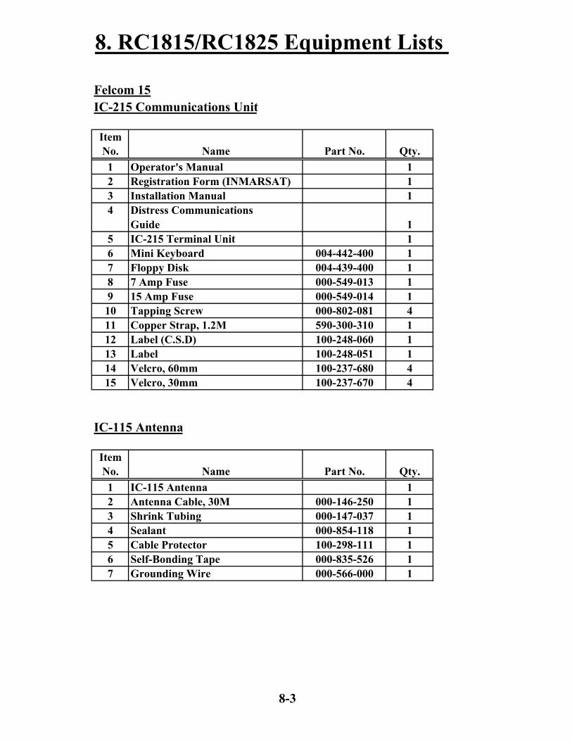
ItemNo. Name Part No. Qty.1 Operator's Manual 12 Registration Form (INMARSAT) 13 Installation Manual 14 Distress Communications
Guide 15 IC-215 Terminal Unit 16 Mini Keyboard 004-442-400 17 Floppy Disk 004-439-400 18 7 Amp Fuse 000-549-013 19 15 Amp Fuse 000-549-014 110 Tapping Screw 000-802-081 411 Copper Strap, 1.2M 590-300-310 112 Label (C.S.D) 100-248-060 113 Label 100-248-051 114 Velcro, 60mm 100-237-680 415 Velcro, 30mm 100-237-670 4
ItemNo. Name Part No. Qty.1 IC-115 Antenna 12 Antenna Cable, 30M 000-146-250 13 Shrink Tubing 000-147-037 14 Sealant 000-854-118 15 Cable Protector 100-298-111 16 Self-Bonding Tape 000-835-526 17 Grounding Wire 000-566-000 1
IC-215 Communications Unit
IC-115 Antenna
8-3

8. RC1815/RC1825 Equipment Lists
ItemNo. Name Part No. Qty.1 IC-305 Distress Unit 12 Tapping Screw 000-802-079 43 Crimp-on Lug 000-538-113 44 Crimp-on Lug 000-108-424 1
ItemNo. Name Part No. Qty.1 IC-306 Alarm Unit 12 Tapping Screw 000-802-079 43 Crimp-on Lug 000-538-113 44 Crimp-on Lug 000-108-424 1
ItemNo. Name Part No. Qty.1 Cable Clamp 100-301-101 12 Tapping Screw 000-802-080 4
IC-315 Installation Materials
IC-305 Distress Unit
IC-306 Alarm Unit
8-4

8. RC1815/RC1825 Equipment Lists
IB-583 NBDP Terminal
ItemNo. Name Part No. Qty.1 IB-583 Terminal Unit 12 Mini Keyboard 004-442-400 13 Floppy Disk 004-439-400 14 3 Amp Fuse 000-549-013 15 Tapping Screw 000-802-081 46 Grounding Wire, 2M 000-108-138 17 Label (C.S.D) 100-248-060 18 Label 100-248-051 19 Velcro, 60mm 100-237-680 410 Velcro, 30mm 100-237-670 4
GMDSS Installation Materials
ItemNo. Name Part No. Qty.1 28 v Bulb RC1-800-020 12 2 Amp Fuse, Mini ATM RC1-800-026 33 PL259 Connector RC1-500-060 44 Printer Paper 000-134-903 25 PP-510 Printer
Operator's Manual 26 Shore Based Maintenance
Certificate 17 Warranty Registration Form 18 E Meter Owners Manual 19 Installation Manual IME-GMD-50Z 110 Dealers Manual OSE-GMD-30Z 111 Daily Test Manual TSE-GMD-30Z 112 Protection Key (FM-8800) RC1-800-034 1
8-5

8. RC1815/RC1825 Equipment Lists
Crate
ItemNo. Name Part No. Qty.1 RC1800 Rack FUSA1800 12 FS-2570C Control Head 13 FM-8800 VHF w/DSC 14 PP-510 Printer 2
8-6

9. RC1840 Equipment Lists
FS-5000 - Transceiver
ItemNo. Name Part No. Qty.1 Operator &
Installation Manual 12 FS-5000 Transceiver 000-056-738 1
FS-5000 - Cables
ItemNo. Name Part No. Qty.1 Control Cable 000-106-043 2
FS-5000 - Control Unit
ItemNo. Name Part No. Qty.1 Control Unit 000-056-731 12 Antenna Coupler 000-056-874 13 Handset 000-112-623 14 Handset Hanger 005-011-950 15 Frequency Table 005-925-890 16 Crimp-on Lug - FV1.25-3 000-538-113 47 Crimp-on Lug - FV1.25-4 000-538-114 18 Hex Bolt 000-800-054 49 Hex Nut 000-863-109 410 Flat Washer - M5 000-864-128 1011 Flat Washer - M6 000-864-129 812 Connector - MP-7 000-500-512 313 Tapping Screw - 5 x 20 000-800-488 1014 US Plug 000-110-961 315 Cable Gland 000-116-434 216 Inline Jack 000-121-824 217 Nylon Washer 000-864-971 418 Blind Cap 100-164-380 1
9-1

9. RC1840 Equipment Lists
DP-6 - Main Unit
ItemNo. Name Part No. Qty.1 Main Unit - DP-6 12 Operator's Manual 13 Operator's Guide 14 Installation Manual 15 Copper Strap 590-300-310 16 Tapping Screw 000-867-553 47 Flat Washer 000-864-128 48 DB25 000-120-946 2
DP-6 - Terminal Unit
ItemNo. Name Part No. Qty.1 Grounding Wire 000-108-138 12 Cable 000-127-108 13 Tapping Screw - 6 x 20 000-802-084 44 Label (Inmar) 100-217-010 15 Velcro Fastener - 30 x 25.4 100-237-670 46 Velcro Fastener - 60 x 25.4 100-237-680 47 Label 100-248-051 18 Label (C. S. D.) 100-248-060 19 Terminal Unit IB581/6 110 Floppy Disk 000-115-862 111 Mini Keyboard 000-138-599 112 Program Floppy Disk 004-447-090 1
9-2

9. RC1840 Equipment Lists
Felcom 15
ItemNo. Name Part No. Qty.1 Operator's Manual 12 Registration Form (INMARSAT) 13 Installation Manual 14 Distress Communications
Guide 15 IC-215 Terminal Unit 16 Mini Keyboard 004-442-400 17 Floppy Disk 004-439-400 18 7 Amp Fuse 000-549-013 19 15 Amp Fuse 000-549-014 110 Tapping Screw 000-802-081 411 Copper Strap, 1.2M 590-300-310 112 Label (C.S.D) 100-248-060 113 Label 100-248-051 114 Velcro, 60mm 100-237-680 415 Velcro, 30mm 100-237-670 4
IC-115 Antenna
ItemNo. Name Part No. Qty.1 IC-115 Antenna 12 Antenna Cable, 30M 000-146-250 13 Shrink Tubing 000-147-037 14 Sealant 000-854-118 15 Cable Protector 100-298-111 16 Self-Bonding Tape 000-835-526 17 Grounding Wire 000-566-000 1
IC-215 Communications Unit
9-3

9. RC1840 Equipment Lists
ItemNo. Name Part No. Qty.1 IC-305 Distress Unit 12 Tapping Screw 000-802-079 43 Crimp-on Lug 000-538-113 44 Crimp-on Lug 000-108-424 1
ItemNo. Name Part No. Qty.1 IC-306 Alarm Unit 12 Tapping Screw 000-802-079 43 Crimp-on Lug 000-538-113 44 Crimp-on Lug 000-108-424 1
ItemNo. Name Part No. Qty.1 Cable Clamp 100-301-101 12 Tapping Screw 000-802-080 4
IC-305 Distress Unit
IC-306 Alarm Unit
IC-315 Installation Materials
9-4

9. RC1840 Equipment Lists
FM-8800 (Installed Unit)
ItemNo. Name Part No. Qty.1 Operator's Manual 12 Operator's Guide 13 Installation Manual 14 Procedure for Distress
Transmission on VHF FM-8800 15 Cable Assy. 000-151-748 16 Spare Parts 005-377-820 17 Accessories- Handset 005-951-920 18 Handset 000-054-223 19 Handset Bracket 005-951-790 110 Self Tapping Screws 000-802-084 4
FM-8800 (Boxed Unit)
ItemNo. Name Part No. Qty.1 Marine VHF Radiotelephone FM-8800 12 Operator's Manual 13 Operator's Guide 14 Installation Manual 15 Procedure for Distress
Transmission on VHF FM-8800 16 Installation Materials 005-377-800 17 Spare Parts 005-377-820 18 Accessories- Handset 005-951-920 19 Handset 000-054-223 110 Handset Bracket 005-951-790 111 Power Cable 000-151-711 1
Included in GMDSS Installation Materials
9-5

9. RC1840 Equipment Lists
DSC-60 Included in GMDSS Installation Materials
ItemNo. Name Part No. Qty.1 Connector - FM-14 - 6 Pin 000-116-185 12 Connector - FM-14 - 7 Pin 000-113-345 13 Connector - FM-MP-7 000-108-859 14 Reducer - MP-7 - MP-M3A 000-108-860 15 Reducer - MP-7 - MP-M5A 000-108-861 16 Installation Manual 17 Operator's Manual 18 Distress Communications
Procedure 19 GMDSS Operating Guidance for
Ship Master in Distress Situations 1
9-6

9. RC1840 Equipment Lists
ItemNo. Name Part No. Qty.1 28 v Bulb RC1-800-020 12 2 Amp Fuse, Mini ATM RC1-800-026 33 PL259 Connector RC1-500-060 44 Printer Paper 000-134-903 25 PP-510 Printer
Operator's Manual 26 Shore Based Maintenance
Certificate 17 Warranty Registration Form 18 E Meter Owners Manual 19 Installation Manual IME-GMD-50Z 110 Dealers Manual OSE-GMD-30Z 111 Daily Test Manual TSE-GMD-30Z 112 Protection Key (FM-8800) RC1-800-034 1
Crate
ItemNo. Name Part No. Qty.1 RC1800 Rack FUSA1800 12 DSC-60 DSC/Watch Receiver 13 FM-8800 VHF w/DSC 14 PP-510 Printer 2
GMDSS Installation Materials
9-7
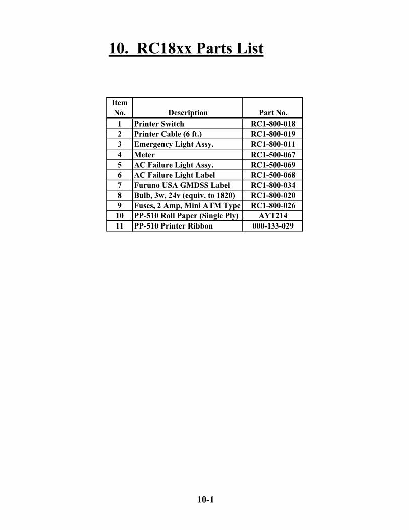
ItemNo. Description Part No.1 Printer Switch RC1-800-0182 Printer Cable (6 ft.) RC1-800-0193 Emergency Light Assy. RC1-800-0114 Meter RC1-500-0675 AC Failure Light Assy. RC1-500-0696 AC Failure Light Label RC1-500-0687 Furuno USA GMDSS Label RC1-800-0348 Bulb, 3w, 24v (equiv. to 1820) RC1-800-0209 Fuses, 2 Amp, Mini ATM Type RC1-800-02610 PP-510 Roll Paper (Single Ply) AYT21411 PP-510 Printer Ribbon 000-133-029
10. RC18xx Parts List
10-1

FURUNO USA GMDSS
H
G
F
E
D
C
B
A
8 7 6 5 4 3 2 1
H
G
F
E
D
C
B
A
8 7 6 5 4 3 2 1
DESCRIPTION
RC1815 / RC1825Interconnect Drawing
FS-2570C
FURUNO
Felcom 15IC-215
FURUNO
IB-583
FURUNOIC-115
000-146-250
IC-315Junction Box
Junction
Ant
Keyboard
PP-510
Keyboard
Printer
24 VDCfromMeterBox
NMEAOut
IC-305
AT-1560or
AT-1560/25
D. ANT
Main Unit
Controller 1
CouplerT/RANT
Handset 1
PP-510
Keyboard
PrinterSwitch
NBDP DTE
Printer
Printer
A
B COM
FS-1570or
FS-2570
000-130-484000-113-360
000-056-950
000-146-652
24 VDCfrom
PR850A
Notes:
1) Local SuppliedFactory Supplied
2) All External Connections Must be Fused.3) Two FM-8800's supplied with each console,
only one shown for simplification.
NMEAfrom
IC-315
24 VDCfromMeterBox
Fax-5Coupler
Long Wire orWhip Antenna
FM-8800See Notes
24 VDCfrom
Meter Box
NMEAfrom
IC-315
T/RANT
RXANT
Handsetand
Bracket
S-1

FURUNO USA GMDSS
H
G
F
E
D
C
B
A
8 7 6 5 4 3 2 1
H
G
F
E
D
C
B
A
8 7 6 5 4 3 2 1
DESCRIPTION
RC1840Interconnect Drawing
ControlUnit
FURUNO
Felcom 15IC-215
FURUNO
IB-581
FURUNOIC-115
000-146-250
IC-315Junction Box
Junction
Ant
Keyboard
PP-510
Keyboard
Printer
24 VDCfromMeterBox
NMEAOut
IC-305
AT-5000
D. ANT
CouplerTX
ANT
Handset
Keyboard
NBDP
24 VDCfrom
PR850A
Notes:
1) Local SuppliedFactory Supplied
2) All External Connections Must be Fused.3) Two FM-8800's supplied with each console,
only one shown for simplification.
24 VDCfromMeterBox
FS-5000Transceiver
RXANT
PP-510
PrinterSwitch
A
B COM
MainUnit
DSC-60
24 VDCfromMeterBox
Rem 2Rem 1
RT
Printer
Printer
NMEAfrom
IC-315
Fax-5Coupler
Long Wire orWhip Antenna
FM-8800See Notes
24 VDCfrom
Meter Box
NMEAfrom
IC-315
T/RANT
RXANT
Handsetand
Bracket
S-2

FURUNO USA GMDSS
H
G
F
E
D
C
B
A
8 7 6 5 4 3 2 1
H
G
F
E
D
C
B
A
8 7 6 5 4 3 2 1
DESCRIPTION
RC1840Detailed Interconnect Drawing
FM-8800See Notes
FURUNO
Felcom 15IC-215
IC-315Junction Box
Junction
Keyboard
Keyboard
NMEAOut
IC-305
Notes:
1) Local SuppliedFactory Supplied
2) All External Connections Must be Fused.3) Two FM-8800's supplied with each console,
only one shown for simplification.
FURUNO
IB-581
Keyboard
2
7
3
DSC-60DSC \ Watch Receiver
1234567
10
89
543219
78
1234562071011121314
DP-6Main Unit
161514131220
1819
1234562071011121314
121314151617181920
REMOTE A
Line Out-HLine Out-CLine In-H
Frame GrndTXD-HRXD-H
Ground
Line In-CTX Key
REMOTE B
RTFrame GrndTXD-HRXD-H
GroundLine Out-HLine Out-CLine In-HLine In-CTX Key
NBDP
123456207
123456207
REM 2
REM 1
FS-5000MF/HF
Control Unit
Ground
Ground
AF TX-H
AF TX-H
AF TX-C
AF TX-C
AF RX-C
AF RX-C
AF RX-H
AF RX-H
TX ON-H
TX ON-H
TX ON-C
TX ON-C
TXD-H
TXD-HRXD-H
RXD-H
Terminal
NMEA
NMEATo IC-315Junction
Box
To IC-315Junction
Box
To IC-315Junction
Box
NMEA
BlueBrownGreenOrangeYellow
RedViolet
Black
BlackRedViolet
YellowOrangeGreenBrownBlue
RCC-15D-206
RCC-15D-206
RC
C-15D
-203
P
P
P
P
P
P
P
Ground
TXD-HRXD-H
Black
RedViolet
Frame Grnd
Frame GrndTXD-HRXD-H
Ground
S-3

DESCRIPTION
Meter Box AssemblyRC1815 / RC1825
Part Number
RC1-800-031
FURUNO USA GMDSS
H
G
F
E
D
C
B
A
8 7 6 5 4 3 2 1
H
G
F
E
D
C
B
A
8 7 6 5 4 3 2 1
2
3
4
5
6
11
5
6
4
3
2
10
3
4
7
2
1
8
6
5
9
Emergency Light
MeterTB 1
TB 2-24VDC
TB 3+24VDC
Batteries
BatteryDisconnectSwitch and
Fuses
BatteryCharger
BatteryNegative
BatteryPositive
ChargerNegative
ChargerPositive
Battery InNegative
Battery InPositive
-24VDC
AC FailNegative
AC FailPositive
Inline BreakersorFuses
FS-1570: 20 AFS-2570: 35 A
FS-1570orFS-2570
TB1
TB2
1
8Meter Fuse
+24VDC
SHUNT
Meter Wiring1) Black2) Blue3) Brown4) Red5) Jumper to #4
Ground
1 2
EmergencyLight Cable
Notes:
1) Local SuppliedFactory Supplied
2) All External Connections Must be Fused.
AC Fail Light
AC Fail Light FuseBatteryIN
AC FailCircuit
24 VDCOutput
RearConnections
ACInput
24 VDCOutput
FrontConnections
PR850A
100 to 240VAC
Not Used
S-4
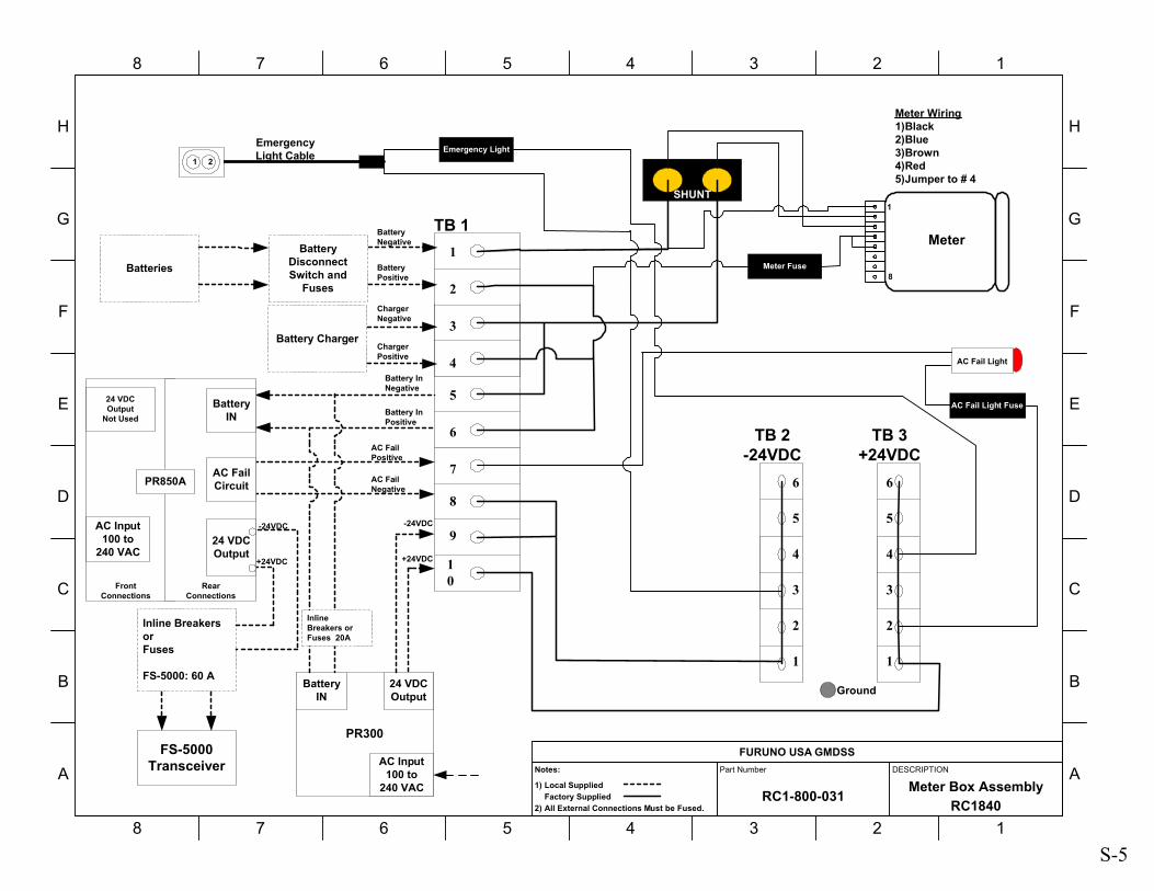
DESCRIPTION
Meter Box AssemblyRC1840
Part Number
RC1-800-031
FURUNO USA GMDSS
H
G
F
E
D
C
B
A
8 7 6 5 4 3 2 1
H
G
F
E
D
C
B
A
8 7 6 5 4 3 2 1
2
3
4
5
6
11
5
6
4
3
2
10
3
4
7
2
1
8
6
5
9
Emergency Light
MeterTB 1
TB 2-24VDC
TB 3+24VDC
Batteries
BatteryDisconnectSwitch and
Fuses
Battery Charger
BatteryNegative
BatteryPositive
ChargerNegative
ChargerPositive
1
8Meter Fuse
SHUNT
Meter Wiring1)Black2)Blue3)Brown4)Red5)Jumper to # 4
Ground
1 2
EmergencyLight Cable
Notes:
1) Local SuppliedFactory Supplied
2) All External Connections Must be Fused.
AC Fail Light
AC Fail Light Fuse
Battery InNegative
Battery InPositive
-24VDC
AC FailNegative
AC FailPositive
Inline BreakersorFuses
FS-5000: 60 A
FS-5000Transceiver
+24VDC
PR300
24 VDCOutput
BatteryIN
-24VDC
+24VDC
BatteryIN
AC FailCircuit
24 VDCOutput
RearConnections
AC Input100 to
240 VAC
24 VDCOutput
Not Used
FrontConnections
PR850A
AC Input100 to
240 VAC
InlineBreakers orFuses 20A
S-5

FURUNO USA GMDSS
H
G
F
E
D
C
B
A
8 7 6 5 4 3 2 1
H
G
F
E
D
C
B
A
8 7 6 5 4 3 2 1
DESCRIPTION
Felcom 15IC-315 Junction Box
Connections
Notes:
1) Local SuppliedFactory Supplied
2) All External Connections Must be Fused.3) Two FM-8800's supplied with each console,
only one shown for simplification.4) The IC-305 and IC-306 are wired in parallel.
RC1815 / RC1825Connections
FURUNO
Felcom 15IC-215
Junction
Keyboard
IC-315Junction Box
1
32
456789101112131415
1
32
456789101112131415
VCCGNDTD/RD-ATD/RD-BN.C.TD-ATD-BRD-ARD-BGNDDMC OUT-HDMC OUT-CDMC IN-HDMC IN-CDMC CTR
DMC
NAV
IC-305/306
Output Sentences:GGA, ZDA, GLL, VTG, RMC, GSV
P
RC1840Connections
TB
FS-1570FS-2570
67
242526
RD3-ARD3-BGND10
NMEA
FM-8800
67
91012
RXD-HRXD-CGND10
NMEA
DP-6
67
3410
RXD-HRXD-CGND10
TB4
FS-5000
67
9106
RXD +RXD -GND10
NMEA
DSC-60
67
345
RD-ARD-BGND10
NMEA
FM-8800
67
91012
RXD-HRXD-CGND10
P
P
P
P
See RC1815 / RC1825 / RC1840DMC-5
Interconnect Drawings
21
IC-305
1
32
45 FG
TD/RD-AGNDVCC
TD/RD-B
3410
21
IC-306
1
32
45 FG
TD/RD-AGNDVCC
TD/RD-B
3410
S-6

12
34
FURUNO USA GMDSS
H
G
F
E
D
C
B
A
8 7 6 5 4 3 2 1
H
G
F
E
D
C
B
A
8 7 6 5 4 3 2 1
DESCRIPTION
RC1815 / RC1825DMC-5
Interconnect Drawing
Notes:
1) Local SuppliedFactory Supplied
2) All External Connections Must be Fused.
DMC-5
TB6MF/HF DSC
1
32
45
27
2928
303132
FS-1570or
FS-2570Transceiver
TB
P
P
34
RXD-H
TXD-HTXD-C
RXD-CGND
TD4-ATD4-BRD4-ARD4-B
GNDDIST_CTR
TB5INMARSAT SES
11
1312
1415
Felcom 15IC-315
Junction Box
DMC_OUT-HDMC_OUT-CDMC_IN-HDMC_IN-C
Frame GrndDMC_CTR
1
32
45
P
P
DIST_IN-H
GND 6
DIST_IN-CDIST_OUT-HDIST_OUT-C
DIST_CTR
12
1
32
456
TB1VHF/DSC No.1
22232021
Frame Grnd
RXD-H
TXD-HTXD-C
RXD-C
1
32
456
TB1VHF/DSC No.2
FM-8800VHF/DSC
22232021
Frame Grnd
RXD-H
TXD-HTXD-C
RXD-C
IF-8810Junction Box
IF-8820DMC I/F
20
2221
2324
P
PRXD-H
TXD-HTXD-C
RXD-CFrame Grnd
FM-8800VHF/DSC
IF-8810Junction Box
IF-8820DMC I/F
20
2221
2324
P
PRXD-H
TXD-HTXD-C
RXD-CFrame Grnd
See FM-8800 Installation Manualfor wiring of IF-8810 and IF-8820
S-7

12
34
FURUNO USA GMDSS
H
G
F
E
D
C
B
A
8 7 6 5 4 3 2 1
H
G
F
E
D
C
B
A
8 7 6 5 4 3 2 1
DESCRIPTION
RC1840 / DMC-5Interconnect Drawing
Notes:
1) Local SuppliedFactory Supplied
2) All External Connections Must be Fused.
DMC-5
TB6MF/HF DSC
1
32
45
1
32
456
DSC-60MF/HF DSC
J4DMC
P
P
34
RXD-H
TXD-HTXD-C
RXD-CGND
DMC OUT-HDMC OUT-CDMC IN-HDMC IN-C
FRAME GRNDDMC CTR
TB5INMARSAT SES
11
1312
1415
Felcom 15IC-315
Junction Box
DMC_OUT-HDMC_OUT-CDMC_IN-HDMC_IN-C
Frame GrndDMC_CTR
1
32
45
P
P
DIST_IN-H
GND 6
DIST_IN-CDIST_OUT-HDIST_OUT-C
DIST_CTR
12
1
32
456
TB1VHF/DSC No.1
22232021
Frame Grnd
RXD-H
TXD-HTXD-C
RXD-C
1
32
456
TB1VHF/DSC No.2
22232021
Frame Grnd
RXD-H
TXD-HTXD-C
RXD-C
FM-8800VHF/DSC
IF-8810Junction Box
IF-8820DMC I/F
20
2221
2324
P
PRXD-H
TXD-HTXD-C
RXD-CFrame Grnd
FM-8800VHF/DSC
IF-8810Junction Box
IF-8820DMC I/F
20
2221
2324
P
PRXD-H
TXD-HTXD-C
RXD-CFrame Grnd
See FM-8800 Installation Manualfor wiring of IF-8810 and IF-8820
S-8