imaging science fundamentalschester f. carlson center for imaging science classical photography and...
Post on 19-Dec-2015
230 views
TRANSCRIPT
Imaging Science Fundamentals Chester F. Carlson Center for Imaging Science
Classical PhotographyClassical Photographyand Geometric Opticsand Geometric Optics
Imaging Science Fundamentals
Imaging Science Fundamentals Chester F. Carlson Center for Imaging Science
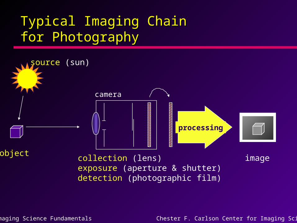
Typical Imaging Chain Typical Imaging Chain for Photographyfor Photography
source (sun)
object
processing
imagecollection (lens)exposure (aperture & shutter)detection (photographic film)
camera
Imaging Science Fundamentals Chester F. Carlson Center for Imaging Science
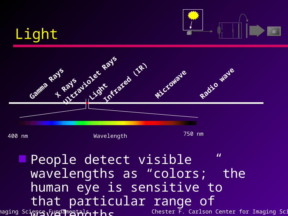
LightLight
Gamm
a Ray
s
Ultrav
iolet
Ray
s
X Ray
s
Light
Infra
red (I
R)
Microwav
e
Radio
wav
e
400 nm 750 nm
People detect visible wavelengths as “colors;” the human eye is sensitive to that particular range of wavelengths.
Wavelength
Imaging Science Fundamentals Chester F. Carlson Center for Imaging Science
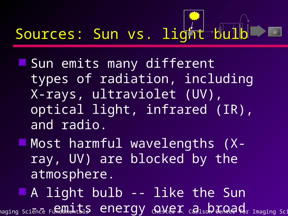
Sources: Sun vs. light bulbSources: Sun vs. light bulb
Sun emits many different types of radiation, including X-rays, ultraviolet (UV), optical light, infrared (IR), and radio.
Most harmful wavelengths (X-ray, UV) are blocked by the atmosphere.
A light bulb -- like the Sun -- emits energy over a broad range of wavelengths; most of its energy comes out in the IR, but a lot comes out in the optical.
Imaging Science Fundamentals Chester F. Carlson Center for Imaging Science
ObjectObject
Energy from the source interacts with the object to be imaged.
Some energy is absorbed, while some energy is reflected or scattered.
The wavelengths that are scattered -- i.e., not absorbed -- are the ones which determine the color of the object.
Imaging Science Fundamentals Chester F. Carlson Center for Imaging Science
CollectionCollection
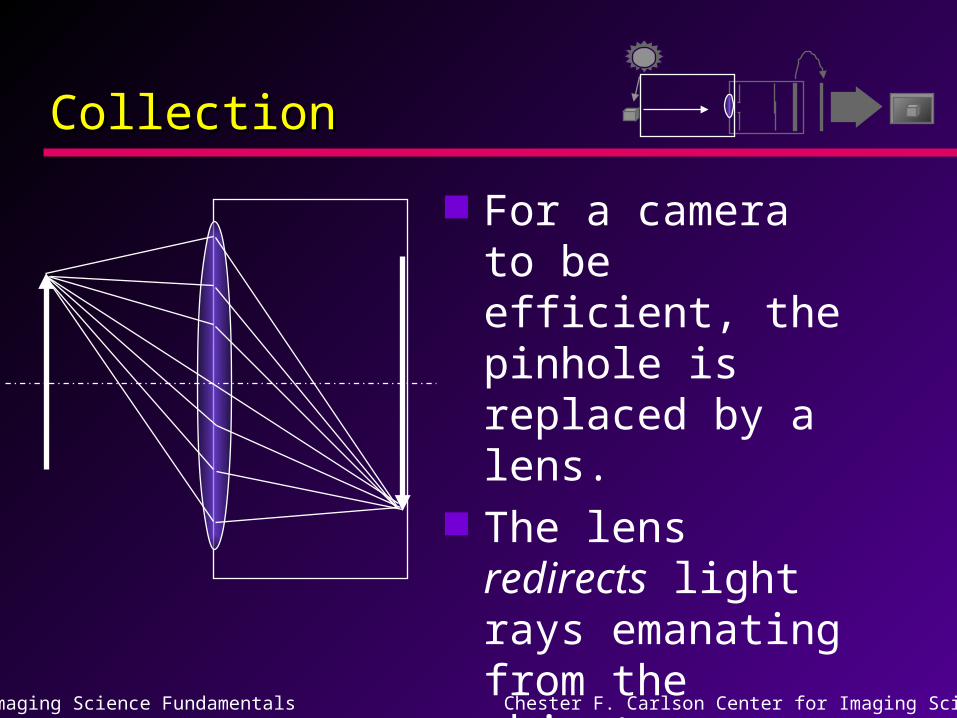
For a camera to be efficient, the pinhole is replaced by a lens.
The lens redirects light rays emanating from the object.
Imaging Science Fundamentals Chester F. Carlson Center for Imaging Science
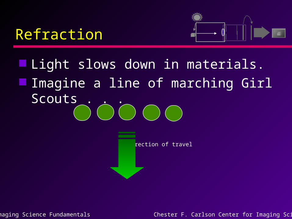
RefractionRefraction
Light slows down in materials. Imagine a line of marching Girl
Scouts . . .
Direction of travel
Imaging Science Fundamentals Chester F. Carlson Center for Imaging Science
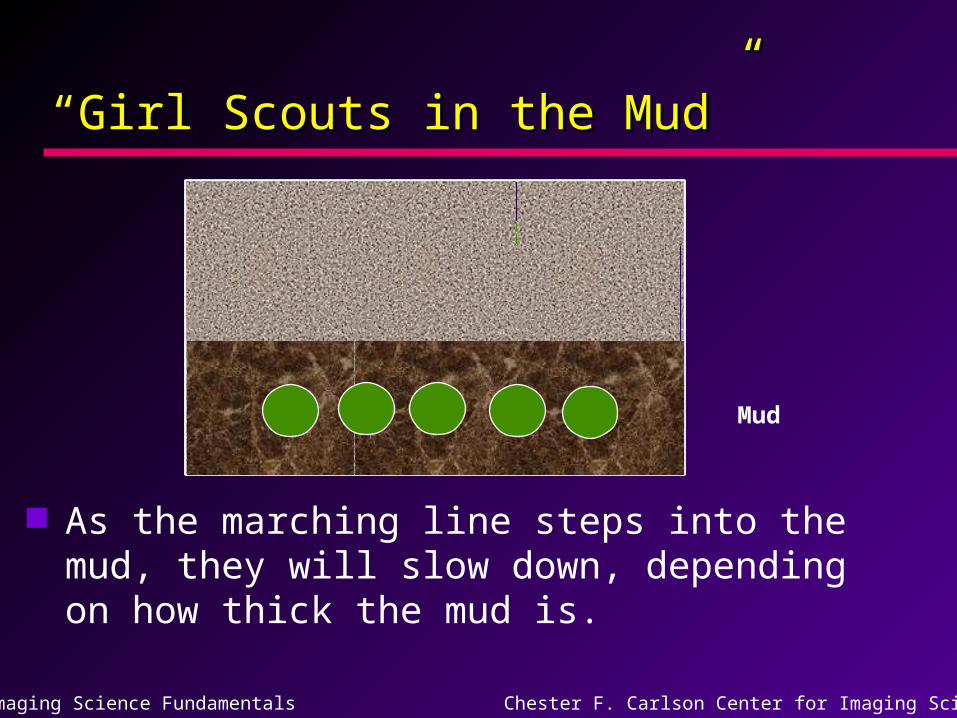
““Girl Scouts in the Mud”Girl Scouts in the Mud”
As the marching line steps into the mud, they will slow down, depending on how thick the mud is.
Mud
Imaging Science Fundamentals Chester F. Carlson Center for Imaging Science
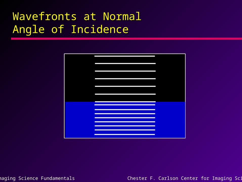
Wavefronts at Normal Wavefronts at Normal Angle of IncidenceAngle of Incidence
Imaging Science Fundamentals Chester F. Carlson Center for Imaging Science
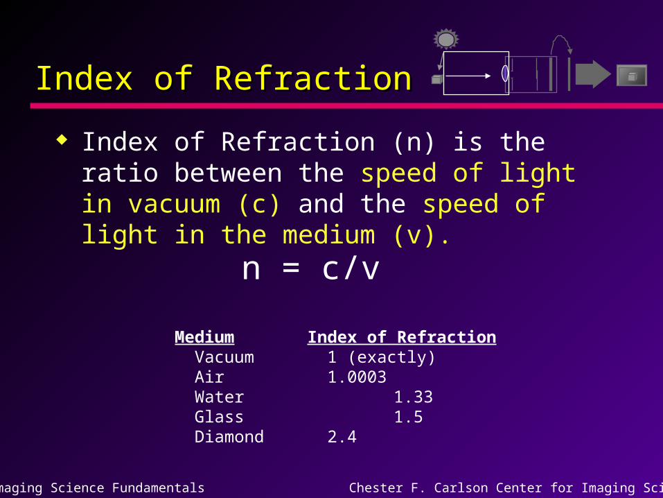
Index of RefractionIndex of Refraction
Index of Refraction (n) is the ratio between the speed of light in vacuum (c) and the speed of light in the medium (v).
n = c/v
Medium Index of Refraction Vacuum 1 (exactly) Air 1.0003 Water 1.33 Glass 1.5 Diamond 2.4
Imaging Science Fundamentals Chester F. Carlson Center for Imaging Science
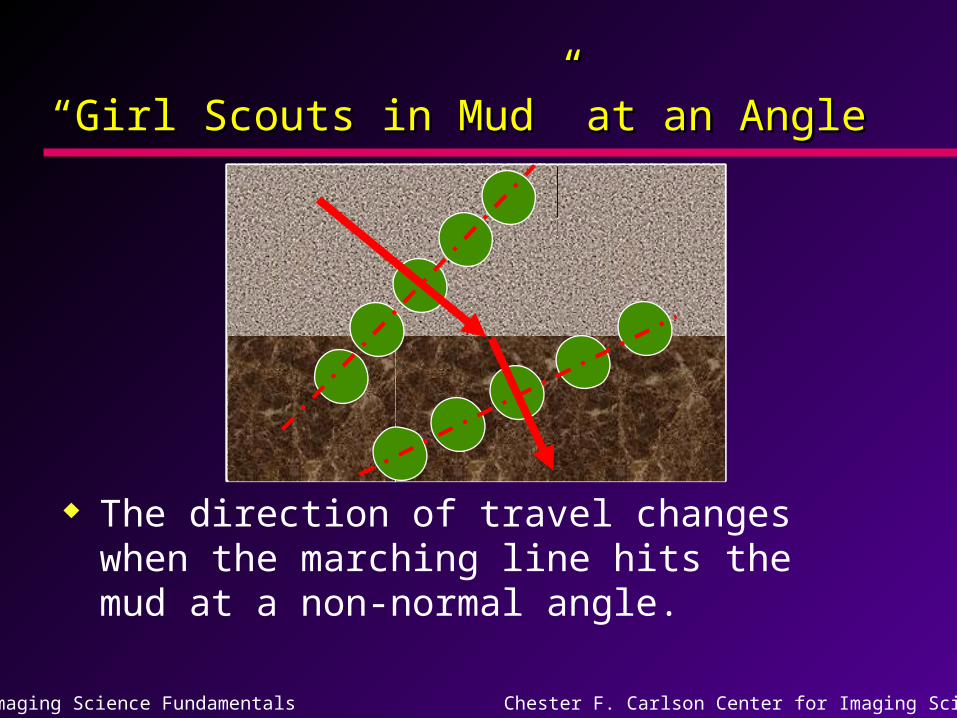
““Girl Scouts in Mud” at an AngleGirl Scouts in Mud” at an Angle
The direction of travel changes when the marching line hits the mud at a non-normal angle.
Imaging Science Fundamentals Chester F. Carlson Center for Imaging Science
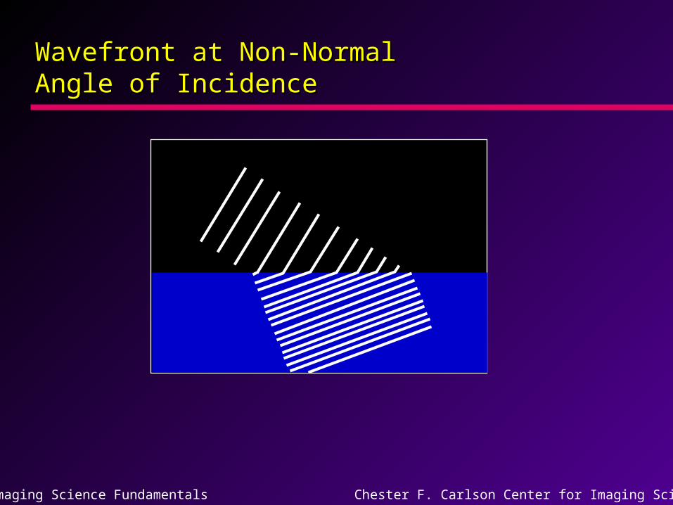
Wavefront at Non-Normal Wavefront at Non-Normal Angle of IncidenceAngle of Incidence
Imaging Science Fundamentals Chester F. Carlson Center for Imaging Science
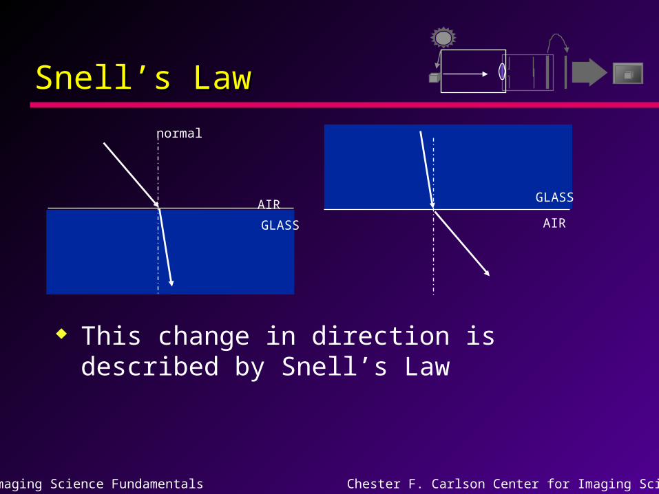
Snell’s LawSnell’s Law
This change in direction is described by Snell’s Law
AIR
GLASS AIR
GLASS
normal
Imaging Science Fundamentals Chester F. Carlson Center for Imaging Science
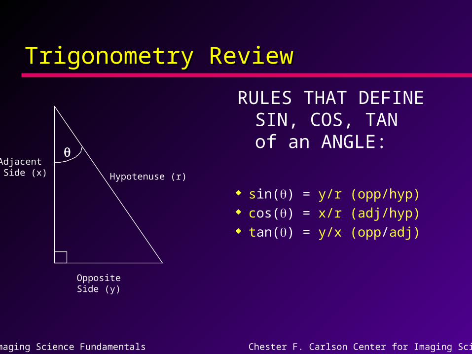
Trigonometry ReviewTrigonometry Review
sin() = y/r (opp/hyp) cos() = x/r (adj/hyp) tan() = y/x (opp/adj)
Adjacent Side (x)
OppositeSide (y)
Hypotenuse (r)
RULES THAT DEFINE SIN, COS, TAN of an ANGLE:
Imaging Science Fundamentals Chester F. Carlson Center for Imaging Science
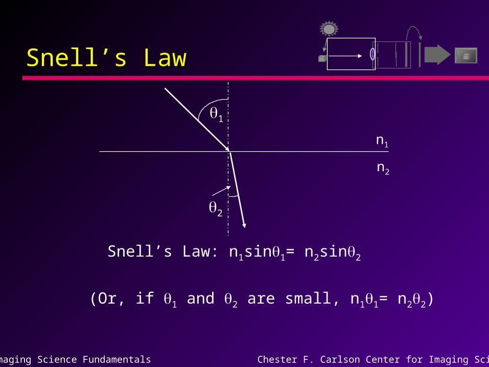
Snell’s LawSnell’s Law
Snell’s Law: n1sin1= n2sin2
1
2
n1
n2
(Or, if 1 and 2 are small, n11= n22)
Imaging Science Fundamentals Chester F. Carlson Center for Imaging Science
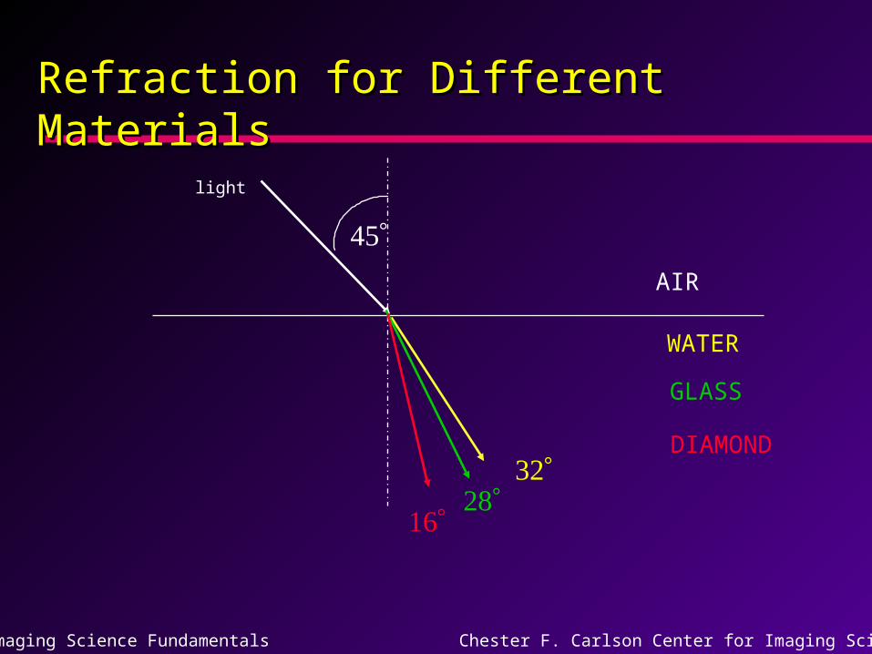
Refraction for Different MaterialsRefraction for Different Materials
AIR
WATER
GLASS
DIAMOND
light
Imaging Science Fundamentals Chester F. Carlson Center for Imaging Science
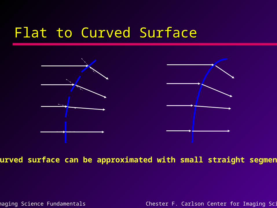
Flat to Curved SurfaceFlat to Curved Surface
A curved surface can be approximated with small straight segments.
Imaging Science Fundamentals Chester F. Carlson Center for Imaging Science
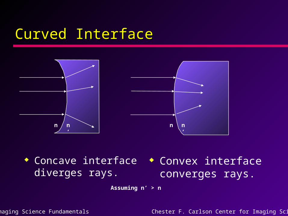
Curved InterfaceCurved Interface
Concave interface diverges rays.
Convex interface converges rays.
Assuming n’ > n
n n’nn’
Imaging Science Fundamentals Chester F. Carlson Center for Imaging Science
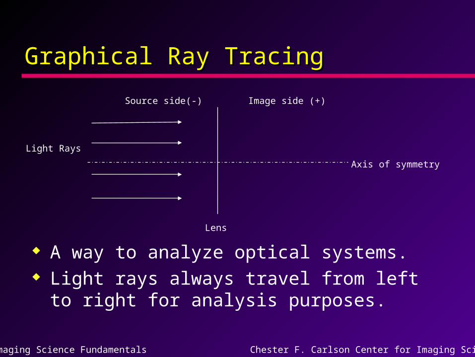
Graphical Ray TracingGraphical Ray Tracing
A way to analyze optical systems. Light rays always travel from left to
right for analysis purposes.
Axis of symmetry
Image side (+)Source side(-)
Light Rays
Lens
Imaging Science Fundamentals Chester F. Carlson Center for Imaging Science
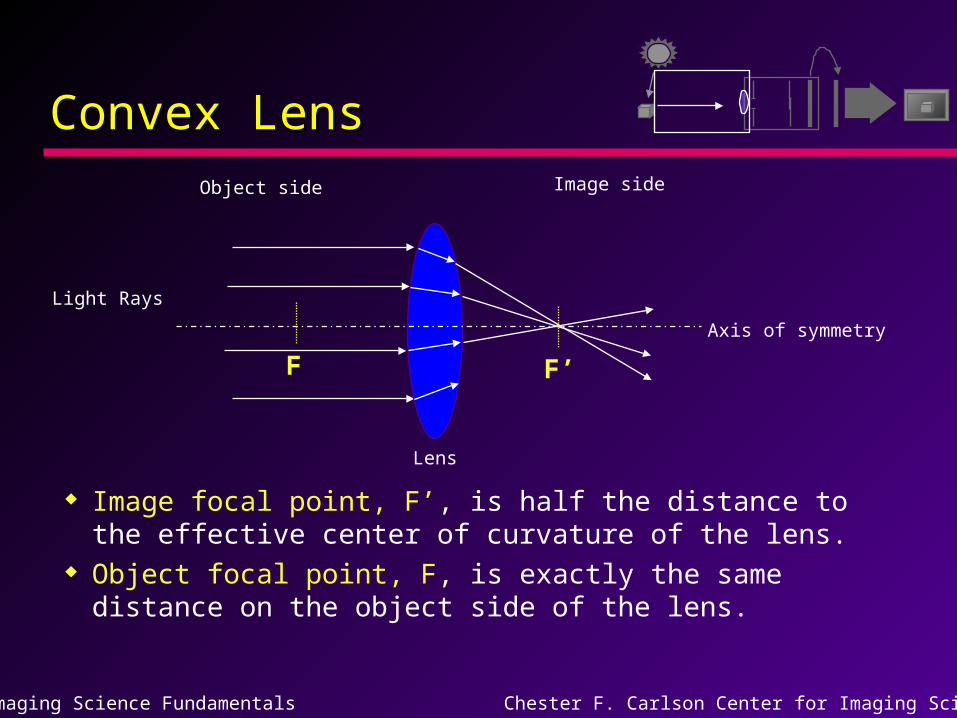
Convex LensConvex Lens
Image focal point, F’, is half the distance to the effective center of curvature of the lens.
Object focal point, F, is exactly the same distance on the object side of the lens.
Axis of symmetry
Light Rays
Lens
F’F
Object side Image side
Imaging Science Fundamentals Chester F. Carlson Center for Imaging Science
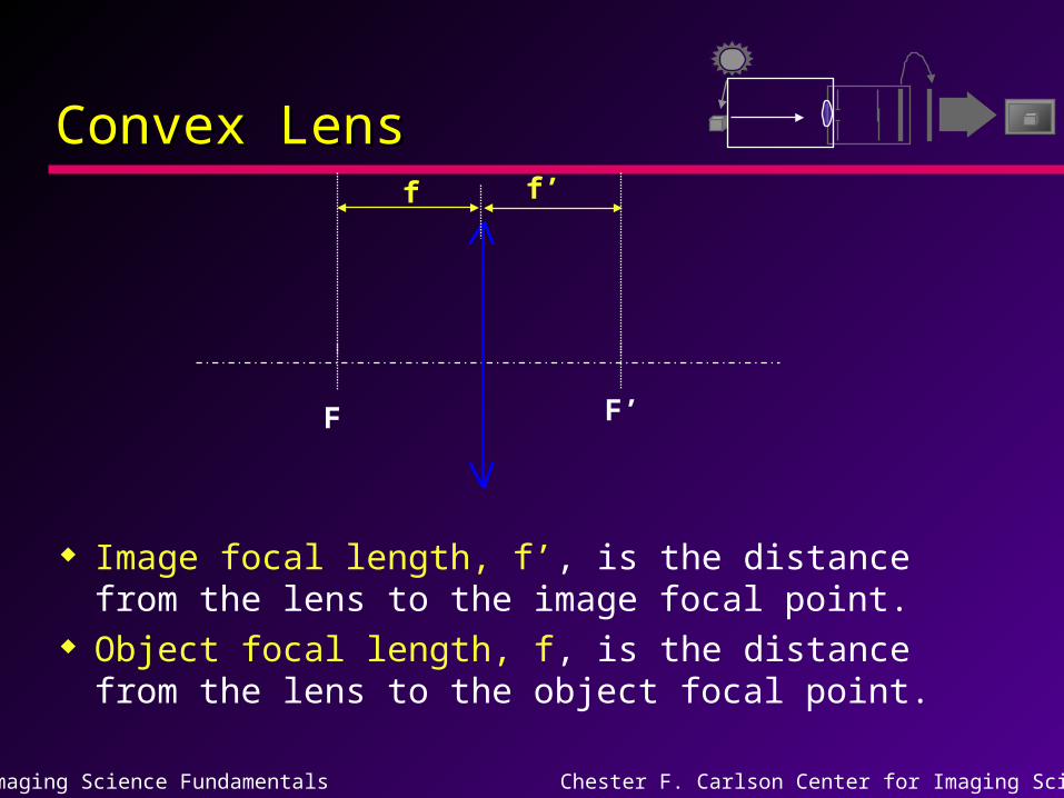
Convex LensConvex Lens
Image focal length, f’, is the distance from the lens to the image focal point.
Object focal length, f, is the distance from the lens to the object focal point.
F’
f’
F
f
Imaging Science Fundamentals Chester F. Carlson Center for Imaging Science
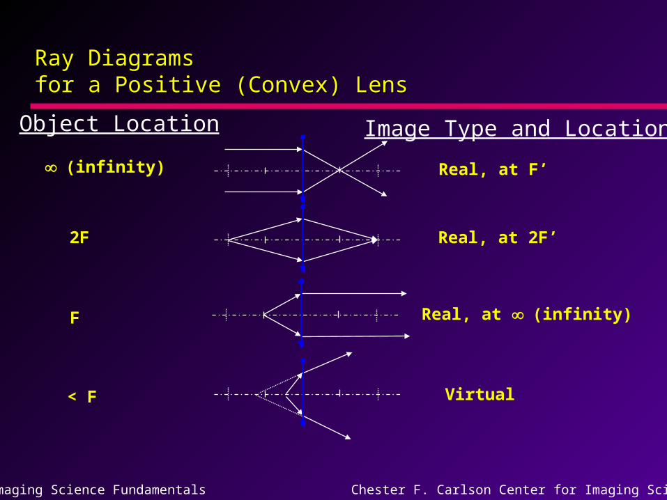
Ray Diagrams Ray Diagrams for a Positive (Convex) Lensfor a Positive (Convex) Lens
(infinity)
Object Location Image Type and Location
Real, at F’
F
Real, at 2F’
Real, at (infinity)
Virtual
2F
< F
Imaging Science Fundamentals Chester F. Carlson Center for Imaging Science
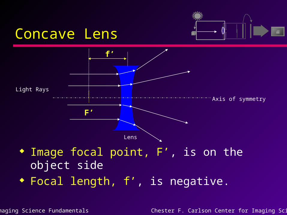
Concave LensConcave Lens
Image focal point, F’, is on the object side
Focal length, f’, is negative.
Axis of symmetry
Light Rays
Lens
F’
f’
Imaging Science Fundamentals Chester F. Carlson Center for Imaging Science
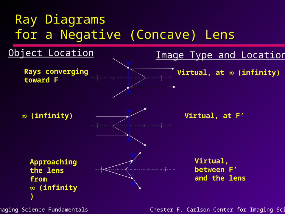
Ray Diagrams Ray Diagrams for a Negative (Concave) Lensfor a Negative (Concave) Lens
Rays convergingtoward F
Object Location Image Type and Location
Virtual, at (infinity)
Approaching the lens from (infinity)
Virtual, at F’
Virtual, between F’ and the lens
(infinity)
Imaging Science Fundamentals Chester F. Carlson Center for Imaging Science
DispersionDispersion
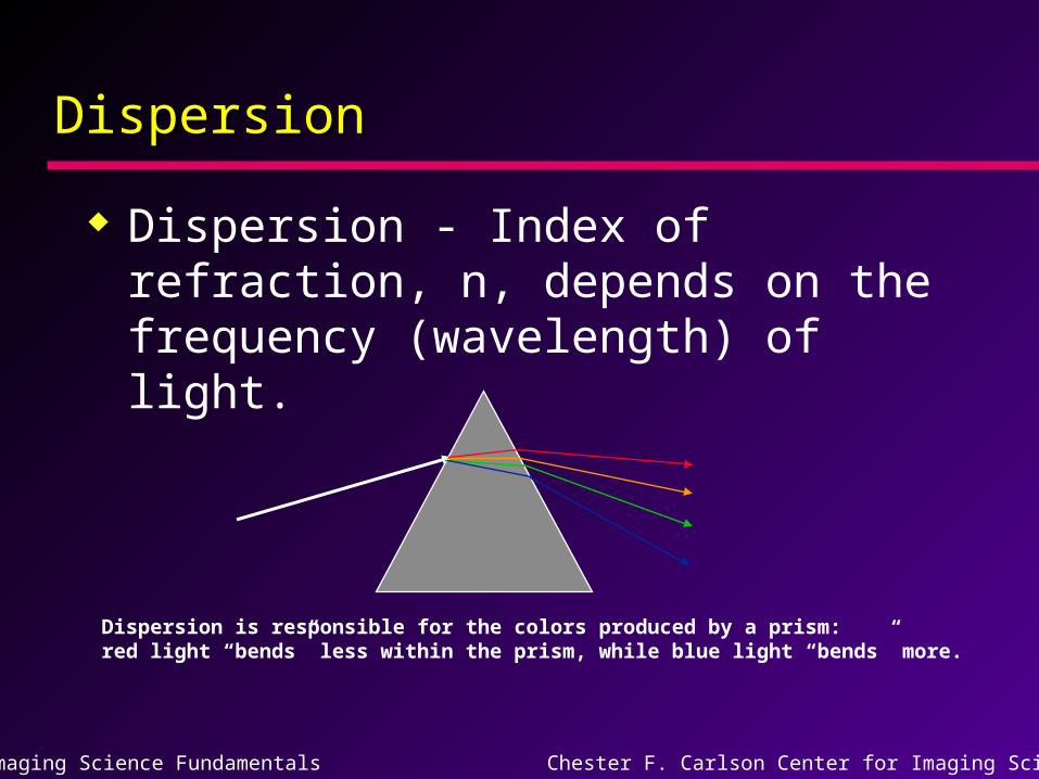
Dispersion - Index of refraction, n, depends on the frequency (wavelength) of light.
Dispersion is responsible for the colors produced by a prism:red light “bends” less within the prism, while blue light “bends” more.
Imaging Science Fundamentals Chester F. Carlson Center for Imaging Science
Chromatic AberrationChromatic Aberration
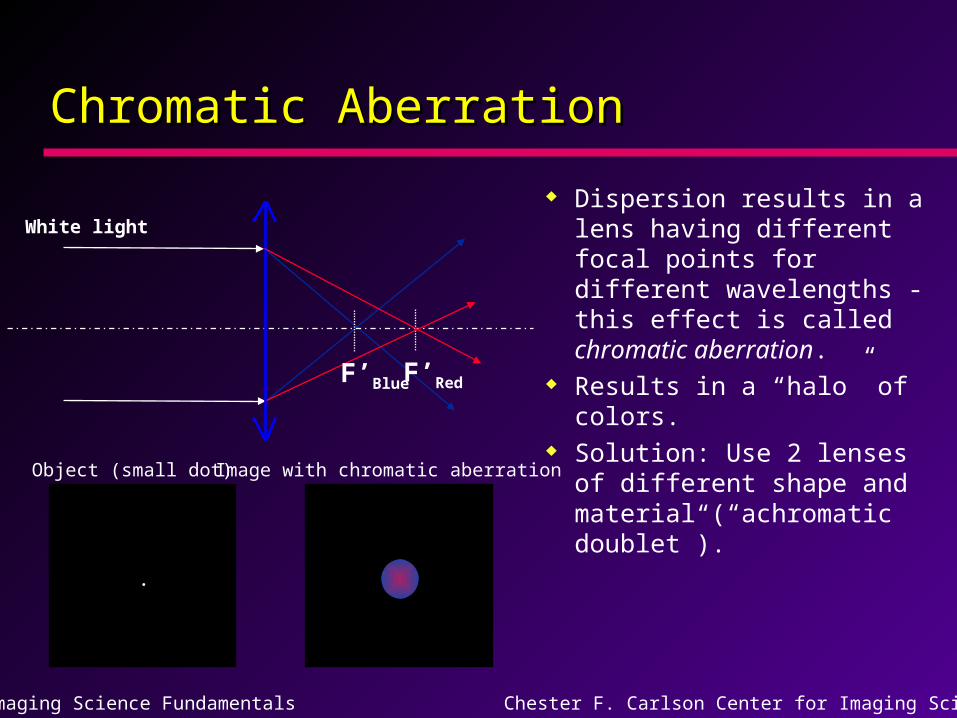
Dispersion results in a lens having different focal points for different wavelengths - this effect is called chromatic aberration.
Results in a “halo” of colors.
Solution: Use 2 lenses of different shape and material (“achromatic doublet”).
F’Red
.
Object (small dot) Image with chromatic aberration
F’Blue
White light
Imaging Science Fundamentals Chester F. Carlson Center for Imaging Science
Spherical AberrationSpherical Aberration
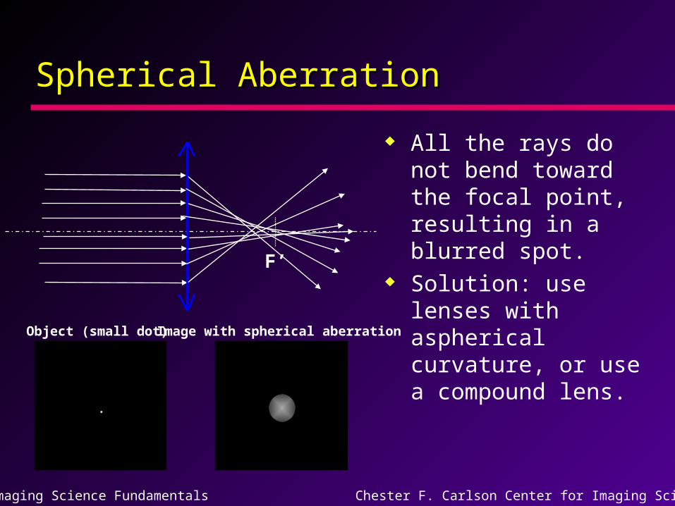
All the rays do not bend toward the focal point, resulting in a blurred spot.
Solution: use lenses with aspherical curvature, or use a compound lens.
F’
.
Object (small dot) Image with spherical aberration
Imaging Science Fundamentals Chester F. Carlson Center for Imaging Science
ExposureExposure
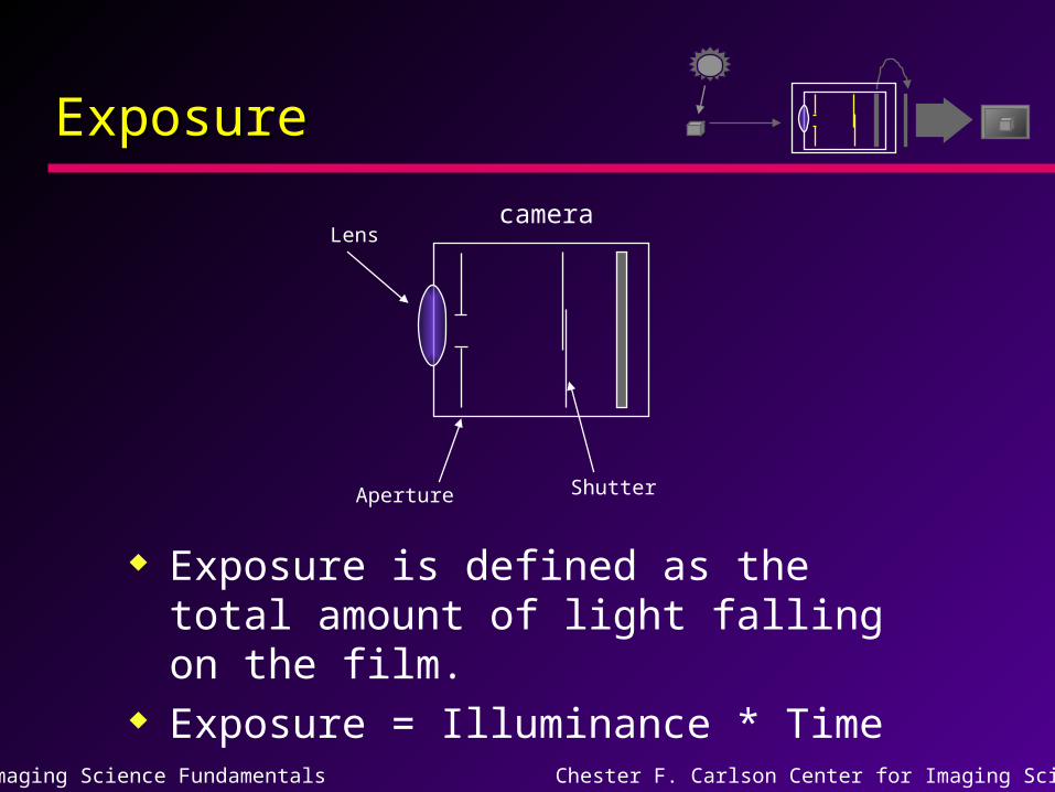
Exposure is defined as the total amount of light falling on the film.
Exposure = Illuminance * Time
camera
Aperture Shutter
Lens
Imaging Science Fundamentals Chester F. Carlson Center for Imaging Science
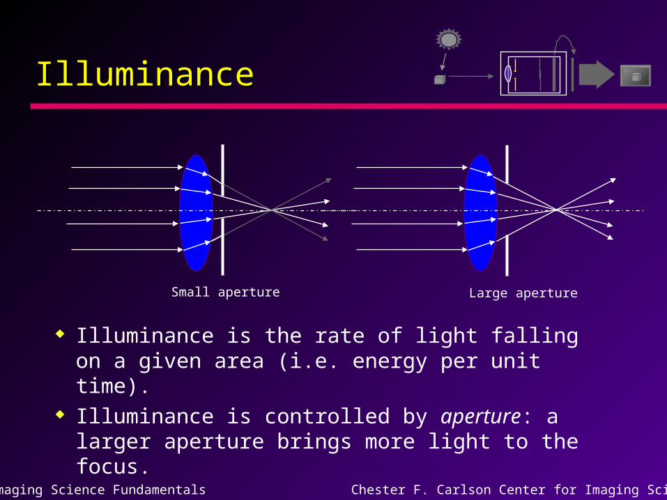
IlluminanceIlluminance
Illuminance is the rate of light falling on a given area (i.e. energy per unit time).
Illuminance is controlled by aperture: a larger aperture brings more light to the focus.
Small aperture Large aperture
Imaging Science Fundamentals Chester F. Carlson Center for Imaging Science
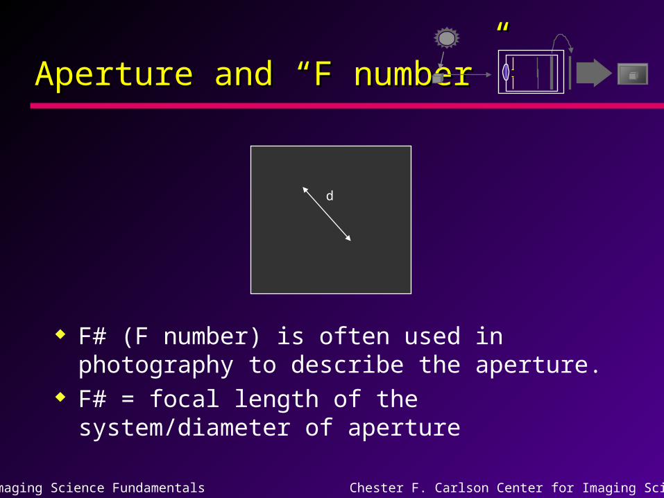
Aperture and “F number”Aperture and “F number”
F# (F number) is often used in photography to describe the aperture.
F# = focal length of the system/diameter of aperture
d
Imaging Science Fundamentals Chester F. Carlson Center for Imaging Science
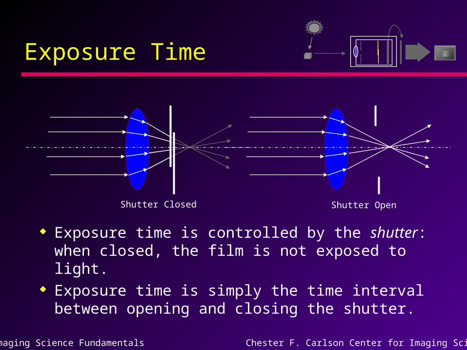
Exposure TimeExposure Time
Exposure time is controlled by the shutter: when closed, the film is not exposed to light.
Exposure time is simply the time interval between opening and closing the shutter.
Shutter Closed Shutter Open
Imaging Science Fundamentals Chester F. Carlson Center for Imaging Science
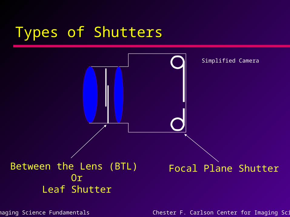
Types of ShuttersTypes of Shutters
Simplified Camera
Between the Lens (BTL) Or
Leaf Shutter
Focal Plane Shutter
Imaging Science Fundamentals Chester F. Carlson Center for Imaging Science
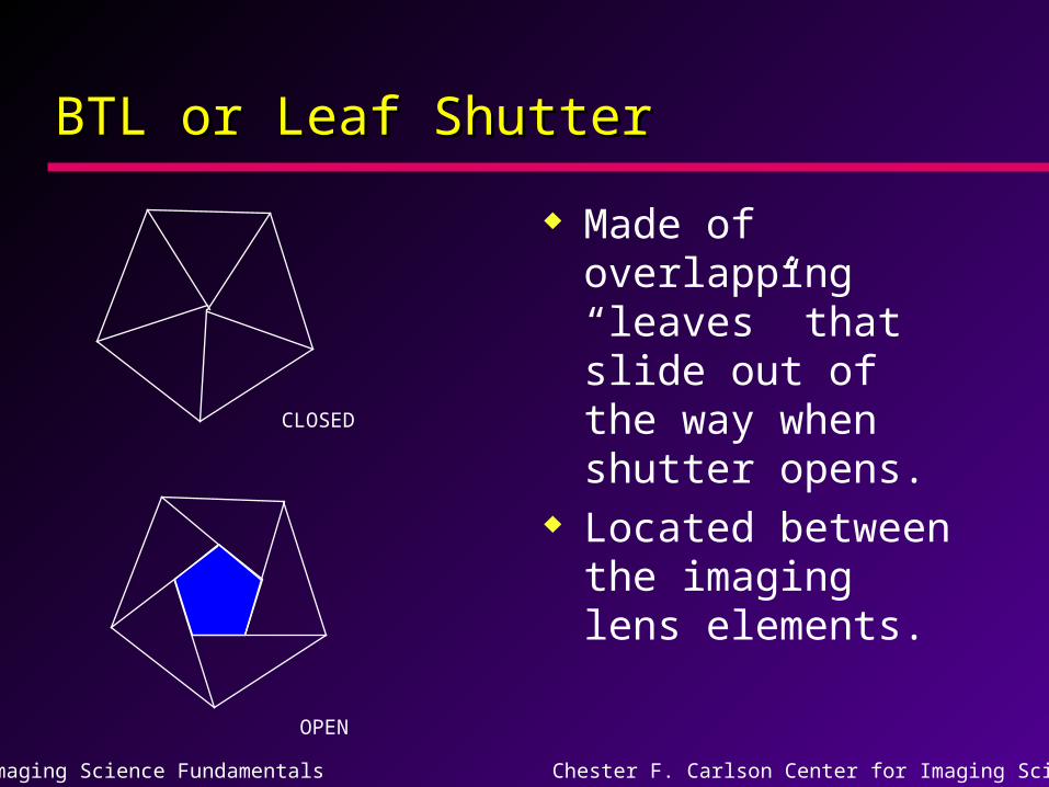
BTL or Leaf ShutterBTL or Leaf Shutter
Made of overlapping “leaves” that slide out of the way when shutter opens.
Located between the imaging lens elements.
CLOSED
OPEN
Imaging Science Fundamentals Chester F. Carlson Center for Imaging Science
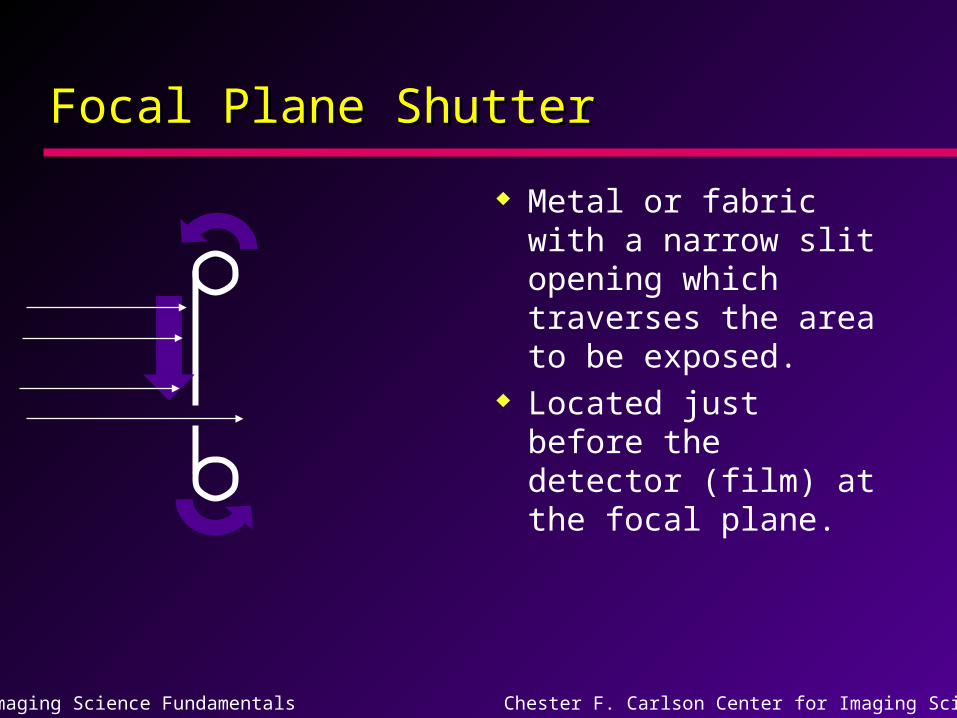
Focal Plane ShutterFocal Plane Shutter
Metal or fabric with a narrow slit opening which traverses the area to be exposed.
Located just before the detector (film) at the focal plane.
Imaging Science Fundamentals Chester F. Carlson Center for Imaging Science
Why control exposure with aperture Why control exposure with aperture and shutter?and shutter?
Flexibility! Fast shutter speed for freezing action
(e.g. sports photography). Slow shutter speed for low light levels
(e.g. sunsets). Small aperture for bright scenes or to
enable longer exposures. Large aperture for low light conditions
(taking candle lit or moon lit pictures).