imaging of scattered radiation for real time tracking of...
TRANSCRIPT

Imaging of Scattered Radiation for Real–Time Tracking of Tumor
Motion During Lung SBRT
April 25nd, 2015

Lung Cancer
• Lung cancer is the most lethal cancer:
– Over 224,000 new diagnoses in the U.S. predicted for 2015
– 159,000 expected deaths in the U.S. predicted for 2015
– More lung cancer related deaths than breast cancer related deaths in women
• Various treatment options:
– Chemotherapy
– Targeted therapy (e.g., monoclonal antibodies)
– Surgery (e.g., wedge resection, lobectomy, pneumonectomy, cryosurgery)
– Radiation therapy (e.g., 3D, IMRT, SBRT)
“Cancer facts and figures 2015”

Lung SBRT
• Promising alternative to surgery
– Large radiation dose in few fractions (e.g., 18Gy×3 or 12Gy×5)
– Increased TCP
– Increased NTCP
•Requires accurate target localization
– Radiation delivery accuracy ~1mm
– Lung tumor motion ~2-3cm
– Internal target not directly visible

Lung SBRT Image Guidance
Current tumor localization methods:
• EPID
• CBCT
• FBCT (kV: CT–on–rails or MV: Tomotherapy)
• Stereoscopic kV imaging (snapshots or fluoroscopic)
• Ultrasound
• Optical Imaging (surface tracking)
• MRI
• Electromagnetic transponder tracking
• Chest expansion/contraction
• Hybrid modalities (e.g., ExacTrac)
J. De Los Santos ,et al. “Image guided radiation therapy (IGRT) technologies for radiation therapy localization and delivery” (2013)
Current limitations:
• Only 2D or limited 3D information
• Additional radiation dose
• Not available during treatment
• Not real-time
• Logistically complex (limited positioning options, collision danger)
• Invasive fiducial implants required
• Poor image contrast
• Not directly imaging the target

Scatter Imaging General Concept:
• Incident radiation interacts within patient
• Energy not deposited carried away
• Scatter from internal structures dependent on material composition
• Image of spatial distribution of scatter gives 2D anatomical information
Benefits:
• No additional radiation dose
• No required fiducial implants
• Flexible detector placement
• Multiple detectors 3D
• Rapid image formation real-time imaging

• Incident beam attenuation
• Probability of scatter event
• Probability of scattering angle 𝜃𝑗𝑘
– Geometric considerations (pinhole size, object-pinhole distance, pinhole-detector distance)
– Klein-Nishina differential cross section
• Scattered radiation attenuation
ℋ𝑗𝑘 = exp − 𝜇 𝑛𝑙𝑛𝑛
× 𝐶 𝑘 × 𝑇 𝑘 × exp − 𝜇 ′𝑚𝑙′𝑚𝑚
𝑔𝑗×1 = ℋ𝑗×𝑘 𝑓𝑘×1 Analytic System Model:
ℋ𝑗𝑘 – signal contribution from scattering element 𝑣𝑘 to detector element 𝑑𝑗
Scatter Imaging
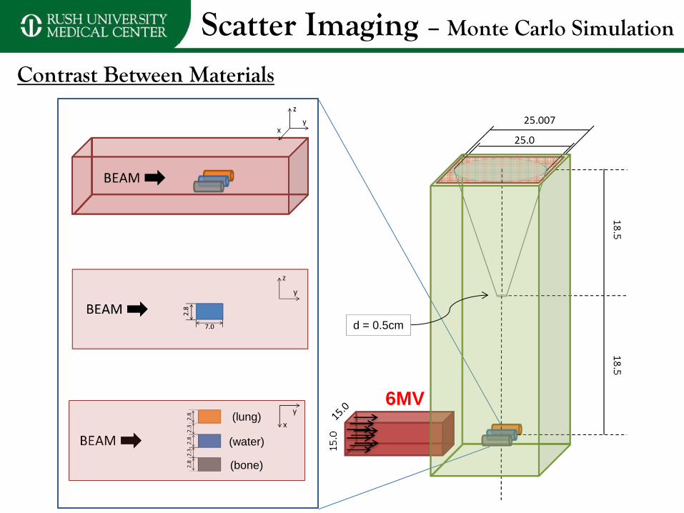
Scatter Imaging – Monte Carlo Simulation
Contrast Between Materials
6MV
d = 0.5cm
(lung)
(water)
(bone)

Scatter Imaging – Monte Carlo Simulation
Contrast Between Materials
• Dose to water cylinder = 0.065 cGy
– SNRL = 1.9, SNRW = 3.3, SNRB = 3.5
• Assuming 𝑁 ∝ 1𝐷𝑜𝑠𝑒 , for 1.0 cGy
– SNRL = 7.6, SNRW = 12.7, SNRB = 13.7
(148x148 pixels, each 0.169x0.169 cm2)
Lung
Water
Bone
Material Monte Carlo Analytic
Calculation
Water 1.00 ± 0.28 1.00
Lung 0.31 ± 0.12 0.35
Bone 1.39 ± 0.40 1.35
# o
f De
tecte
d P
artic
les

Scatter Imaging – Monte Carlo Simulation
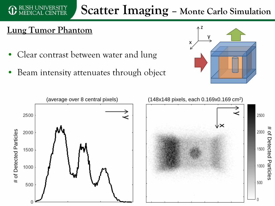
Lung Tumor Phantom
6MV
d = 0.5cm

Scatter Imaging – Monte Carlo Simulation
Lung Tumor Phantom
• Dose to isocenter = 0.153 cGy
– SNR = 8.3
– CNR = 4.8
– 1200 cGy/min 0.153 cGy < 0.01 sec
• Assuming 𝑁 ∝ 1𝐷𝑜𝑠𝑒 , for 1.0 cGy
– SNR = 21.2
– CNR = 12.3
– 1200 cGy/min 1.0 cGy = 0.05 sec
(148x148 pixels, each 0.169x0.169 cm2)
# o
f De
tecte
d P
artic
les
𝐶𝑁𝑅 =𝑆𝑇 − 𝑆 𝐿𝜎𝑇
Scatter Imaging – Monte Carlo Simulation
Lung Tumor Phantom
• Clear contrast between water and lung
• Beam intensity attenuates through object
(148x148 pixels, each 0.169x0.169 cm2)
# o
f De
tecte
d P
artic
les
# o
f D
ete
cte
d P
art
icle
s
(average over 8 central pixels)

Scatter Imaging – Experimental Data
Contrast Between Materials
• Lung SBRT treatment parameters used:
– Varian TrueBeam Linac
– 6MV FFF
– Dose rate = 1200 MU/min
• 5000 MU delivered
• Diagnostic flat panel detector
• Nuclear medicine pinhole camera
• Background image acquired/subtracted

Scatter Imaging – Experimental Data
Contrast Between Materials
Material Monte Carlo Analytic
Calculation Experiment
Water 1.00 ± 0.28 1.00 1.00 ± 0.08
Lung 0.31 ± 0.12 0.35 0.37 ± 0.08
Bone 1.39 ± 0.40 1.35 1.36 ± 0.08
(Simulation) (Experiment)

Scatter Imaging – Experimental Data
Contrast Between Materials
Material Monte Carlo Analytic
Calculation Experiment
Water 1.00 ± 0.28 1.00 1.00 ± 0.08
Lung 0.31 ± 0.12 0.35 0.37 ± 0.08
Bone 1.39 ± 0.40 1.35 1.36 ± 0.08

Scatter Imaging – Experimental Data
Lung Tumor Phantom
HU
Solid Water = 9.1 ± 3.4 Bolus = -7.1 ± 3.7 Cork = -828.5 ± 13.2

Scatter Imaging – Experimental Data
Lung Tumor Phantom

Scatter Imaging – Experimental Data
Lung Tumor Phantom
• Lung SBRT treatment parameters used:
– Varian TrueBeam Linac
– 6MV FFF
– Dose rate = 1200 MU/min
• Various MU delivered
• Diagnostic flat panel detector
• Nuclear medicine pinhole camera
• Background image acquired/subtracted

Scatter Imaging – Experimental Data
Lung Tumor Phantom

Scatter Imaging – Experimental Data
Lung Tumor Phantom

Summary and Conclusions
• Scatter imaging may be useful for image based tumor tracking
– No additional radiation dose
– No required fiducial implants
– Flexible detector placement
– Multiple detectors 3D
– Rapid image formation real-time imaging
• Analytic model developed to describe scatter imaging
• Preliminary Monte Carlo simulations
– Scatter imaging differentiates objects of different composition
– Using a simplified lung tumor model the target can be clearly identified
• Preliminary experimental measurements agree qualitatively with simulation results
– Images as fast as 0.5sec (10MU) begin to resolve target Real-time imaging

Thank You
April 25nd, 2015

©2007 RUSH University Medical Center

©2007 RUSH University Medical Center

Analytic System Model
ℋ𝑗𝑘 = exp − 𝜇 𝑛𝑙𝑛𝑛
× 𝐶 𝑘 × 𝑇 𝑘 × exp − 𝜇 ′𝑚𝑙′𝑚𝑚
2 MeV
0.407 MeV
3.5 cm
1.4 cm
Material 𝐶 𝑘𝒁
𝑨 𝝆
𝒈
𝒄𝒎𝟑
𝝁
𝝆 𝒄𝒎𝟐
𝒈
(2 MeV)
𝝁 𝒄𝒎−𝟏 (2 MeV)
exp − 𝜇 𝑛𝑙𝑛𝑛
(2 MeV)
𝝁
𝝆 𝒄𝒎𝟐
𝒈
(0.407 MeV)
𝝁 𝒄𝒎−𝟏 (0.407 MeV)
exp − 𝜇 ′𝑚𝑙′𝑚𝑚
(0.407 MeV)
ℋ𝑗𝑘
Water 1.00 1.00 0.0493 0.0493 0.8415 0.1061 0.1061 0.8620 0.725 (1.00)
Lung 0.28 0.29 0.0461 0.0142 0.9515 0.1053 0.0305 0.9582 0.255 (0.35)
Bone 1.69 1.824 0.0490 0.0840 0.7453 0.0991 0.1808 0.7764 0.978 (1.35)
(Assume scatter at 90o, so ignore 𝑇 𝑘)
Material Monte Carlo Experiment
Water 1.00 ± 0.28 1.00 ± 0.08
Lung 0.31 ± 0.12 0.37 ± 0.08
Bone 1.39 ± 0.40 1.36 ± 0.08

Defining SNR
• Specifically looking at “tumor” in image
𝑆𝑁𝑅 =𝑆𝑇𝜎𝑇
– 𝑆𝑇 is the image intensity, averaged over a central region within the
tumor
– 𝜎𝑇 is the standard deviation of the image intensity over the same central region within the tumor
Note: SNR and CNR should be approximately proportional to 𝑑𝑜𝑠𝑒 and to linear pixel
dimension

Defining CNR
• Specifically looking at “tumor” in image • Tumor is embedded in lung • CNR is a metric to quantify how well tumor can be differentiated from the surrounding lung relative to the random noise present in the image
𝐶𝑁𝑅 =𝑆𝑇 − 𝑆 𝐿𝜎𝑇
– 𝑆𝑇 is the image intensity, averaged over a central region within the
tumor
– 𝑆 𝐿 =𝑆𝐿1+𝑆𝐿22
, where 𝑆𝐿1 and 𝑆𝐿2 are image intensity, averaged over regions within the lung surrounding the tumor
– 𝜎𝑇 is the standard deviation of the image intensity over the same central region within the tumor used to calculate 𝑆𝑇
Note: SNR and CNR should be approximately proportional to 𝑑𝑜𝑠𝑒 and to linear pixel
dimension

Scatter Imaging – Experimental Data
Contrast Between Materials
• Signal Average over 18,216 pixel cylinder ROI
• Noise Standard deviation in cylinder ROI
• Background Average over surrounding 189,880 pixel ROI
• SNRL = 6.1, SNRW = 6.7, SNRB = 5.3
• CNRL = 4.4, SNRW = 5.3, SNRB = 4.1

Scatter Imaging – Monte Carlo Simulation

Lung SBRT Image Guidance
Current limitations:
• Only 2D or limited 3D information
• Additional radiation dose
• Not available during treatment / Not real-time
• Logistically complex (limited positioning options, collision danger)
• Invasive fiducial implants required
• Poor image contrast
• Not directly imaging the target

Scatter Imaging – Experimental Data
Lung Tumor Phantom
Signal Intensity
Dose
(MU) 5000 1000 500 200 100 50 10
Time
(sec) 250 50 25 10 5 2.5 0.5
SNR 149.9 99.3 78.8 49.8 32.3 30.0 8.9
CNR 29.1 19.0 15.5 9.7 6.7 5.5 4.1
Bea
m D
irec
tio
n