image-based modeling techniques for artistic rendering
TRANSCRIPT
Clemson UniversityTigerPrints
All Theses Theses
5-2010
IMAGE-BASED MODELING TECHNIQUESFOR ARTISTIC RENDERINGBynum Murray iiiClemson University, [email protected]
Follow this and additional works at: https://tigerprints.clemson.edu/all_theses
Part of the Fine Arts Commons
This Thesis is brought to you for free and open access by the Theses at TigerPrints. It has been accepted for inclusion in All Theses by an authorizedadministrator of TigerPrints. For more information, please contact [email protected].
Recommended CitationMurray iii, Bynum, "IMAGE-BASED MODELING TECHNIQUES FOR ARTISTIC RENDERING" (2010). All Theses. 777.https://tigerprints.clemson.edu/all_theses/777

IMAGE-BASED MODELING TECHNIQUES FOR ARTISTIC RENDERING
A Thesis Presented to
the Graduate School of Clemson University
In Partial Fulfillment of the Requirements for the Degree
Master of Arts Digital Production Arts
by Bynum Edward Murray III
May 2010
Accepted by: Timothy Davis, Ph.D. Committee Chair
David Donar, M.F.A. Tony Penna, M.F.A.

ii
ABSTRACT
This thesis presents various techniques for recreating and enhancing two-
dimensional paintings and images in three-dimensional ways. The techniques include
camera projection modeling, digital relief sculpture, and digital impasto. We also explore
current problems of replicating and enhancing natural media and describe various
solutions, along with their relative strengths and weaknesses. The importance of artistic
skill in the implementation of these techniques is covered, along with implementation
within the current industry applications Autodesk Maya, Adobe Photoshop, Corel
Painter, and Pixologic Zbrush. The result is a set of methods for the digital artist to create
effects that would not otherwise be possible.
.

iii
DEDICATION
This thesis is dedicated to my parents. Their support enabled me to make it this
far, and to Carrie my partner and muse.

iv
ACKNOWLEDGMENTS
I would like to thank the faculty of the Clemson DPA for their instruction and
guidance throughout the program, and especially my advisor, Dr. Timothy Davis, for his
assistance throughout the thesis process. I would also like to acknowledge the students of
the DPA program, for their support and camaraderie.

v
TABLE OF CONTENTS
Page
TITLE PAGE .................................................................................................................... i ABSTRACT ..................................................................................................................... ii DEDICATION ................................................................................................................ iii ACKNOWLEDGMENTS .............................................................................................. iv LIST OF FIGURES ....................................................................................................... vii CHAPTER I. INTRODUCTION ......................................................................................... 1 II. BACKGROUND ........................................................................................... 3 2.1 Traditional Painting ........................................................................... 3 2.2 Three Dimensionality in Painting ...................................................... 4 2.3 Impasto ............................................................................................... 6 2.4 Relief Sculpture ................................................................................. 8 2.5 Camera Projection Modeling ............................................................. 9 2.6 Three-Dimensional Mapping Types and Applications .................... 10 2.6.1 Bump Mapping ................................................................... 11 2.6.2 Normal Mapping ................................................................. 12 2.6.3 Displacement Mapping ....................................................... 13 2.7 Conclusion ....................................................................................... 14 III. TECHNIQUES ............................................................................................ 15 3.1 Creating Geometry using Camera Projection Modeling .................. 15 3.2 Creating Normal Maps using Corel Painter ..................................... 20 3.3 Relief Sculpture from a Painting in Zbrush ..................................... 23 3.4 Creating Digital Impasto with ZBrush ............................................. 30 3.4.1 Paint Brush Alphas ............................................................. 30 3.4.2 ZBrush 2.5D Depth Creation .............................................. 33 3.4.3 ZBrush 3D Impasto Depth Creation ................................... 35 IV. SCHILDERMENNEKE: A CASE STUDY ................................................. 40

vi
Table of Contents (Continued) V. CONCLUSION ............................................................................................ 50 APPENDICES A. PAINTER DEPTH CREATION PROCESS ............................................... 52 REFERENCES .............................................................................................................. 59

vii
LIST OF FIGURES
Figure Page 2.1 Escaping Criticism, by Pere Borrell del Caso ............................................... 5 2.2 Apotheosis of St. Ignactius, by Andrea Pozzo, Church of Sant’Ignazio, Rome ............................................................................. 6 2.3 Summer Building Site, 1952, Frank Auerback ............................................... 7 2.4 High and Low Relief Sculpture ..................................................................... 9 2.5 Sphere With and Without Bump Map ......................................................... 11 2.6 Normal and Bump Maps Applied to a Sphere ............................................. 12 2.7 Bump Map and Displacment Map Applied to a Sphere .............................. 13 3.1 A Rendered Frame from the Opening Shot ................................................. 16 3.2 Outline of the Geometry in the Painting ...................................................... 17 3.3 The Outlines of the Model Geometry with Texture Applied ..................................................................................... 18 3.4 Front and Side View of the Model ............................................................... 19 3.5 Brushes in Painter ........................................................................................ 21 3.6 Two Planes with and without a Specular Alpha .......................................... 22 3.7 Tile of The Delphic Sibyl by Michelangelo ................................................. 23 3.8 Outlines of the Major Forms ........................................................................ 24 3.9 Highlights of the Various Sections .............................................................. 25 3.10 Basic Facial Anatomy and Construction...................................................... 25 3.11 Sketch of Form Height ................................................................................. 27

viii
List of Figures (Continued) Figure Page 3.12 Final Sculpted Form ..................................................................................... 28 3.13 Three Versions of the Tile ........................................................................... 29 3.14 Alpha Brushes- Soft Flat, Round Hard, and Soft Round ............................. 31 3.15 The Alpha Tool Palette ................................................................................ 32 3.16 ZBrush in 3D Edit mode .............................................................................. 35 3.17 ZBrush Painted Zplane in Edit Mode .......................................................... 37 3.18 The ZMapper Interface ................................................................................ 38 3.19 The Tool Texture Palette ............................................................................. 39 4.1 View and Lighting Transition of the Dawn Scene ....................................... 43 4.2 The Completed Harvest Scene ..................................................................... 44 4.3 The Color and Normal Map Textures for the Harvest ................................. 45 4.4 Still Frames of the Hand Animated Elements used in the Harvest Scene............................................................................... 45 4.5 The Wireframe and Textured Model of the Crows Scene........................................................................................... 46 4.6 Still Frame from the Hand Animated Sky ................................................... 47 4.7 Crows Transition Frames ............................................................................. 47 4.8 Top and Side View of the Final Scene......................................................... 48 4.9 The Original and Normal Mapped Water .................................................... 49 4.10 Composited Elements of the Night Sky ....................................................... 49 A.1 The Impasto Brush Settings ......................................................................... 53

ix
List of Figures (Continued) Figure Page A.2 The Impasto Brush Settings ......................................................................... 54
A.3 The Exported Top Image ............................................................................. 55 A.4 The Levels Options Box .............................................................................. 56 A.5 The Color, Alpha, and Normal Maps........................................................... 57 A.6 The Texture Rendered on a Plane ................................................................ 58

CHAPTER ONE
INTRODUCTION
Paintings and other traditional media are complex in style and structure. Like
most things in the real world, the amount of information contained in a single
brushstroke, much less an entire painting, can be quite large. While current computing
power may not allow the recording of all this detail, one area of information in paintings
that has received little notice thus far is depth.
Almost all traditional art has some amount of depth information that is not
captured by a simple print or photograph. Many painters throughout history, including
Rembrandt and van Gogh, have purposefully used the technique of impasto, or thickly
applied paint, to control the final look of the painting. The depth information of
individual brushstrokes affects the way light interacts with the media and ultimately
enhances the overall image.
While a camera can capture the instance light on a canvas or sculpture, only
through the viewer’s movement will the surface quality emerge to the human eye. This
phenomenon illustrates one of the major differences between viewing the original and a
print. Through the use of three-dimensional computer graphics, the digital artist can more
closely replicate the depth and surface quality, as well as enhance two-dimensional
imagery in new ways.
This thesis will focus on four ways to enhance traditional paintings as well as the
complete digital creation of imagery that closely resembles that of traditional paintings.
Each technique explores a different approach to the imagery and produces a different
2
result.
This work uses a variety of software applications to produce results. Corel Painter
is used to create the natural media imagery through the use of the impasto brush.
Painter’s surface lighting features are then manipulated to create depth maps. Autodesk
Maya facilitates the camera projection technique, and its included renderers generate the
final results of the processes. Adobe Photoshop is used to create normal maps as well as
other image map work, while the primary tool for the creation of digital relief sculptures
and for additional painting techniques is Pixologic’s Zbrush. These techniques offer new
options to the artist’s toolset.
Chapter 2 begins with background information on the traditional arts of painting
and relief sculpture, as well as information on special texture mapping techniques.
Chapter 3 introduces the processes that replicate or enhance traditional paintings on the
computer and shows the implementation of these processes. Chapter 4 presents a brief
case study of the application of the techniques in the short film Shildermenneke. Chapter
5 concludes the work and offers suggestions for future directions of development.

3
CHAPTER TWO
BACKGROUND
2.1 Traditional Painting Painting is a mode of visual communication and expression. Paintings can be
naturalistic and representational, or completely abstract. They can be loaded with
narrative content, symbolism, and emotion [PREBLES2009].
Painting began with pre-historic humans and has been incorporated into all
cultures. Throughout history, from tribal cultures to the great civilizations, painting has
been a constant practice. Paintings have been used throughout history as a way to visually
communicate ideas. In many cases, paintings have been used to educate and express ideas
to the illiterate. In Western art oil painting, frescos, tempera, and watercolor painting are
the most common [PREBLES2009]. In the modern era, mixed media paintings that
include other materials such as sand, clay, paper and others capable of adhering to the
paint have been created. Paintings have been made on most any surface.
2.2 Three-dimensionality in Painting
Presumably, the ancient Greeks were the first to incorporate three-dimensionality
into paintings around 500 BC. While no examples of ancient Greek panel painting
survive, writers of the day describe some of the artists as possessing exceptional abilities
in modeling the form [JANSON1964].

4
The later Roman painters introduced the techniques of trompe-l'oeil, pseudo-
perspective, and pure landscape. These techniques would later form the foundation of
classical art [JANSON1964].
Trompe-l'oeil, a French term meaning “trick the eye” is an art technique that
involves producing realistic imagery to create the illusion that the rendered objects appear
in three dimensions, instead of only two [JANSON1964]. A typical trompe-l'oeil mural
may depict doorways, colonnades or windows in a larger space. Some painters add small
trompe-l'oeil features to their paintings, exploring the boundary between image and
reality. For example, a fly might appear to be sitting on the painting's frame, a piece of
paper might appear to be attached to a board, or in one case, a painted rug that has a
wrinkled corner, appears on the floor enticing the viewer to straighten it. Figure 2.1
shows trompe-l'oeil in a 19th Century Painting.

5
Figure 2.1 Escaping Criticism, by Pere Borrell del Caso
A thousand years after the Romans, the Renaissance was characterized by a
revival of the techniques of Ancient Greece and Rome, which led to many changes in the
technical aspects of painting from the dark and middle ages. During the Renaissance,
painters began to enhance the realism of their work by applying true perspective to
produce three-dimensionality on a flat plane or canvas more authentically
[JANSON1964]. Artists also began to develop new techniques in the rendering of light,
as well as exploring its emotive qualities. Unsurprisingly, the use of trompe-l'oeil also
became widely used.
With the understanding of perspective drawing gained in the Renaissance, Italian
painters began breaking from painting flat walls to create illusionist ceiling paintings.

6
These works were done in fresco and relied on perspective techniques such as
foreshortening to sell the illusion of the image to the viewer below [JANSON1964]. In
this way, some church ceilings contain false domes and ornaments that are only paint, not
sculpture. One such example is Andrea Pozzo's Apotheosis of St Ignatius (Figure 2.2).
Figure 2.2 Apotheosis of St. Ignactius, by Andrea Pozzo, Church of Sant'Ignazio, Rome
2.3 Impasto
The Italian word impasto most commonly refers to a painting technique where
paint is applied to a surface thickly enough such that the brush strokes are visible
[JANSON1964]. When dry, impasto provides texture and depth with the paint slightly
protruding from the canvas.

7
Impasto in painting results in several interesting characteristics. First, impasto
forces the light to reflect in a particular way, giving the artist additional control over the
play of light on the painting. In this way, the technique can add unique expressiveness to
an artistic piece. The technique was first used by masters such as Rembrandt and Titian to
represent folds in clothes or jewels; it was then contrasted with more delicate painting to
accentuate the result [JANSON1964]. Vincent van Gogh used impasto frequently for
emotional expression in his bush strokes. In its extreme form, impasto can be used to
make a painting almost a three-dimensional sculptural work, such as those produced by
Frank Auerback (Figure 2.3).
Figure 2.3 Summer Building Site, 1952, Frank Auerback

8
Since impasto gives texture to the painting, it is often used in contrast to more
flat, smooth, or blended techniques. Elements of this technique will be digitally recreated
later in this thesis.
2.4 Relief Sculpture
A sculpture that is modeled not “in the round” (open on all sides but the base), but
raised or lowered from a surface, is known as a relief. Reliefs are common throughout the
world on the walls of monuments and facades of buildings [JANSON1964]. There are
two types of relief, high and low (Figure 2.4). They are differentiated by how much of the
form is modeled “in the round.” In low relief the overall depth of a projecting image is
shallow; the background is compressed or completely flat. Coins are good examples of
low relief.
High relief occurs when the form is sculpted more than half in the round.
Although the degree of relief within both types may vary across a composition, the most
prominent features, such as faces, are often in higher relief [JANSON1964]. The two are
very often combined in a single work; e.g., most high-relief sculptures contain sections in
low-relief for composition and contrast.

9
Figure 2.4 High and Low Relief Sculpture
2.5 Camera Projection Modeling
Camera projection is the technique of projecting an image as a reference for a new
construct, whether a painting or model. The process has its origins in the camera
obscura, where an image of the outside world is projected onto a flat surface for tracing
[JANSON1964]. Beginning in the golden age of film, similar techniques were used to
create sets using forced perspective in such a way as to make them appear larger than
they physically were.
In the realm of computer graphics, camera projection modeling is a technique that
allows models to be created from a background image that is non-orthographic. The
three-dimensional elements can then be texture-mapped with the background image
projected onto them to create a faux three-dimensional set design both quickly and easily.

10
The main difficulty of the process is matching the perspective of the 3D camera to
that of the camera used in the photography or artistic rendering. This task can be a
challenge, even under ideal conditions where the focal settings are known. Trying to
match a hand-drawn conceptual image, therefore, is even more difficult and poses more
challenges because the artist may not have used proper perspective.
In many cases, a three-dimensional modeler cannot always rely on being supplied
with orthographic drawings. Even with the extra time spent setting up the camera,
building the models, and later readjusting the model, this process will be faster and more
accurate than the conventional method of eyeballing the concept art or photography, and
has the added benefit of cheating the texture maps.
2.6 Three-Dimensional Mapping Types and Applications
Texture mapping, or image mapping, is the process of wrapping flat two-
dimensional images around a three-dimensional object and is one of the most effective
ways to give surface quality to a model. Using a combination of different images attached
to various channels in a shader system, a virtually unlimited number of surfaces can be
created, ranging from the fanciful to realistic. Commonly used channels, or nodes, for
textures include: color, specularity, incandescence, transparency, bump, normal, and
displacement. For this thesis, the last three will be explored.

11
2.6.1 Bump Mapping
Bump mapping is a trick that simulates the small details on an object's surface
without actually displacing the geometry [BIRN2006]. Bump mapping is used primarily
to give a tactile response to an otherwise smooth surface by changing the surface normals
of an object to respond to light as though additional details had been present in the
geometry. Bump mapping uses a grayscale image with brighter tones representing higher
elevations. An area of flat tone will have no effect on a surface (Figure 2.5). A drawback
of bump mapping occurs in the outline, or silhouette, of the object [BIRN2006]. Since no
real deformation is occurring, the edges of the geometry remain smooth. Another
drawback is a smooth line where two pieces of bump mapped geometry intersect.
Figure 2.5 Sphere With and Without Bump Map

12
2.6.2 Normal Mapping
Normal mapping is similar to bump mapping in that it replicates additional detail
on a model; however, it has the advantage of directly perturbing surface normals. In
bump mapping, pixel brightness is interpreted as height, and a slope derived from the
heights of adjacent pixels determines the angle assigned to surface normals [BIRN2006].
In a normal map, each pixel specifies the angle on the surface normal through its color
channels represented by RGB (red, green, blue) images. Normal maps are commonly
used to apply high-resolution model detail on a low-resolution polygon object in real-
time applications and games. Normal maps, however, suffer from the same shortcomings
as bump mapping in terms of smooth silhouettes (Figure 2.6).
Figure 2.6 Normal and Bump Maps Applied to a Sphere

13
2.6.3 Displacement Mapping
Displacement mapping uses a grayscale image similar to a bump map, but the
brightness of the map is used to actually change the shape of a surface (Figure 2.7). The
brighter the tone in a displacement map, the farther out a point on the surface will be
displaced. Many shaders also support an offset in order to key in the displacement effect.
Most displacement is achieved through a process known as tessellation. This
method subdivides the geometry of the model at render time to a finer degree than it is in
the working scene [BIRN2006]. This advanced tessellation has the advantage of creating
a highly detailed model with deformation in the silhouette and edges, but at the expense
of a much longer render time. Current trends use up to 32-bit images exported from
applications such as ZBrush to create highly detailed and accurate displacement maps.
Figure 2.7 Bump Map and Displacment Map Applied to a Sphere

14
2.7 Conclusion
In this chapter background information about traditional painting and sculpting
techniques were given, along with an overview of the technical processes involved.
Several image types and their effects were also presented. The next chapter describes the
process and implementation of various methods dealing with image-based modeling
techniques.

15
CHAPTER THREE
TECHNIQUES
This chapter explores techniques and methods for the creation and enhancement of two-
dimensional paintings and images. These techniques begin with camera projection
modeling. Next, the creation of digital impasto is presented. The last part of the chapter
covers digital relief sculpture and an alternate method of digital impasto creation.
3.1 Creating Geometry using Camera Projection modeling.
Camera projection is a technique that allows models to be made over a
background plate. The main difficulty of the process is matching the perspective in the
3D camera to that of the physical camera, or artist perspective of the reference image.
This task can be a challenge, even when the focal settings are known. Further, matching a
hand-drawn image can be more difficult since the perspective may not be true to a
physical setting.
The technique was applied in the short film Schildermeneke throughout the
animation. The presented example is the first scene of the film (Figure 3.1). The layout
called for a slow tilt of a town as the dawn sun rose high in the sky. In order to create this
effect, the background image was placed in the scene at the origin, along with a camera
with an extremely long field of view (200mm) to simulate the inferred distance between
the subject and the artist. The field of view flattened out the perspective such that a
compressed model could be used, and allowed for the maximum tilt of about 15 degrees
without breaking the model or appearing unnatural.

16
Figure 3.1 A Rendered Frame from the Opening Shot
The modeling process was approached similarly to that of a pop-up book. The
process was started by outlining the primary forms (Figure 3.2). Since many of the
buildings are perpendicular to the camera, they could be built using simple polygons with
extruded forms for roofs and walls. The edges of these extensions were pulled back away
from the camera to generate depth of perspective and allow the geometry to cast proper
shadows.

17
Figure 3.2 Outline of the Geometry in the Painting
Once the majority of the buildings were assembled, the camera was animated for
its range of tilt. This process aided in the placement of the buildings in space to help
create a convincing scene. Once the buildings’ depths were set, a ground plane was
created that was low in the front and high in the back to fit the image. The sides of the
buildings were then extended so that they merged with the ground plane, providing a
cohesive model enabling cast shadows to provide mass to the buildings (Figure 3.3).

18
Figure 3.3 The Outlines of the Model Geometry with Texture Applied
Once the model was completed (Figure 3.4), UVs were assigned to the geometry.
Using the project UV from camera option in Maya effectively matched the image and
perspective.
For this project a simple planar mapping proved to be the most effecive method.
The background image was connected to the color channel of the shader, and then
applied to all the objects to provide visual feedback for manually editing the UVs. Next
the buildings UVs were selected, arranged, and scaled to fit in their proper locations.

19
Manual edits of the planar projection map corrected some of the stretching and artifact
issues that were affecting the model.
Using this method, a model or scene can be quickly sculpted without a need for
multiple orthographic images. The other advantage is that the projected image is directly
applicable as a texture map. This method is ideal for creating dynamic lighting effects on
an otherwise static background.
Drawbacks to this technique arise when a moving camera is involved, since once
the view is shifted from the modeled point the illusion of depth is quickly lost. Just as the
illusionistic ceiling paintings in the renaissance do not work when the viewer moves,
neither will the projection modeled scene. Keeping the camera within fifteen degrees of
center works well. If more angle of center is required, a greater focal length can help, but
only to a certain point.
This technique will not replace a fully modeled scene or prop, but it gives the
artist the ability to add depth and form to an otherwise flat backdrop. It also presents a
lighting designer with surfaces to light, and objects upon which shadows can be cast.
Figure 3.4 Front and Side View of the Model
20
3.2 Creating Normal Maps using Corel Painter
Corel Painter is a natural media painting program designed to replicate real world
traditional media such as acrylics, oils, pens, watercolor pencils, etc. One of the brush
types, Impasto, uses a depth mask for replicating thick paint as well as other special
effects (Figure 3.5).
One problem with viewing photographs and prints of famous paintings is that the
viewer never sees how the light reflects off the canvas. This limitation is a great loss,
especially when the painter has applied thick layers of paint to the canvas, thus adding a
three-dimensional element to an otherwise flat image. This depth is what needs to be
captured for correct presentation.
For the Shieldermenneke project, the depth information was needed to aid in the
texture mapping of the scene geometry. Unfortunately, Painter does not include a method
for exporting this information.

21
Figure 3.5 Brushes in Painter
Ryan Clark created a tutorial on creating normal maps from digital photography
[CLARK2007] using a single stable camera and four photographs of the subject. A
flashlight was used to create a directional light source on the subject. By simulating his
flashlight and camera with Painter’s Surface Lighting properties, a collection of four
images could be created and mixed in Photoshop to create a normal map.
The process of creating the normal maps uses the same technique. While the
technical process is outlined in Appendix A, it is summarized here. Instead of using a
flashlight to light a physical surface, Painter allows the customization of a surface light.
By changing the surface light properties and removing the color information from the
image, four images can be extracted representative of the depth information contained in
the image. These four images are then modified and assembled together in Photoshop to
create a final complete normal map.

22
When creating textures using the preceding technique, certain issues arise with
transparency. If the specular color channel is left unassigned, shininess will appear in
areas with no color. The solution is to either create a separate alpha image, or to attach
the alpha from the color channel to the specular color channel in the shader. The alpha
helps reduce the specular highlights in areas where none should exist (Figure 3.6).
Although Painter is a natural media paint program, some of its special effects
brushes can be used to create interesting results."Gloopy" effects, as well as liquid metal
and depth effecting brushes, are included in the package. In fact, the real strength of using
Painter as an artistic tool comes from this highly customizable and robust brush system.
Figure 3.6 Two Planes with and without a Specular Alpha

23
3.3 Relief Sculpture from a Painting in Zbrush
The goal of this technique was to create a relief sculpture from an image in
Pixologic's Zbrush. While possible to implement this technique using virtually any
image, using an image or painting that models the form well with light will yield the best
results. Once completed, the model can be directly exported as a polygonal mesh or
normal or displacement map for application in a three-dimensional package such as
Maya.
The image chosen was a small section of Michelangelo’s Sistine Chapel, the
Delphic Sibyl (Figure 3.7). This image is notable for its composition and framing, as well
as the rendering of the subject’s form with light. The image contains a single strong light
source, which allows for easier testing of the digital sculpture's form later in the process.
Figure 3.7 Tile of The Delphic Sibyl by Michelangelo
In order to create a three-dimensional sculpture from a flat image, analyzing the
depth of the represented form is necessary. A little foresight and planning applied to the

24
process at this point will help insure a better result in the end. The first step to matching
the depth is to notice and outline the major contours, creases, and contrasts found in the
image (Figure 3.8).
Figure 3.8 Outlines of the Major Forms
Once the outlines are created, the image should be subdivided into major regions,
to determine not only their depth contrast, but also how each region relates to its
neighbors. In Figure 3.9 the image is broken into four major sections: the face, shoulders,
hair, and scarf. These regions operate as areas of similar detail so that as the sculpt
progresses, no area is left without attention.

25
Figure 3.9 Highlights of the Various Sections
The face needs to be sculpted more in the round than other parts of the image.
By its nature, the face contains a high degree of depth contrast, as well as much of the
detail in the final sculpt. The nature of facial anatomy (Figure 3.10) dictates that the form
of the face will have a high point on the ball of the nose, and lower points around the
edges, with large variations of middle information around the eyes, mouth, and chin.
Figure 3.10 Basic Facial Anatomy and Construction

26
The neck and shoulder area are grouped because in this image, they have a similar
secondary nature. The main points of interest are the edges where the neck meets the
face, as well as the shoulder. Since the neck and shoulder are perpendicular to each other,
this region contains high contrast, further exaggerated by the pushing in of the neck, and
the pulling out of the shoulder and arm. Special note must be taken of the scarf tucking in
behind the neck, which eliminates the neck as the lowest part of the sculpture.
The hair is the simplest and most stylized part of the image. Since the hair has
little depth information and is bordered by high contrast regions, a simple light treatment
can be used to separate it from the background plate.
The scarf is the most juxtaposed region of the painting. The scarf has almost as
much detail as the face, and contains the greatest variance of depth information in the
image. The scarf is made more complex by its use in the image to cast shadows on other
forms. The altitude variance is what makes the scarf a challenge, but also holds the key to
the sculpture. The highest points of the scarf should be therefore at least even with the
forehead, if not the ball of the nose, in order to cast shadows on the face. Further, the
lowest areas of the scarf should be even with, if not recessed into, the background. This
arrangement especially holds true as the scarf nears the neck.
With the outline established, and the major forms and points of interest mapped
out, a depth map of the image can be produced (figure 3.11). The depth sketch is optional
and could be created as a separate image, or used as the start of the sculpture by denoting
major forms. At this point the sculpting begins. The major forms are added first followed
by subdivisions to increase the level of detail.

27
Figure 3.11 Sketch of Form Height
The artistic techniques necessary to sculpt the face, hair, and folds of cloth do not
fall within the scope of this thesis. Volumes of information have been produced on this
subject. Whether the artist is looking for information on ancient Egyptian hieroglyphic
relief, or Baroque-era sculptures in French cathedrals, most likely many books exist
describing that technique, such as [LANTERI1985]. For this project [SPENCER2008]
was found useful for computer-based works.

28
Figure 3.12 Final Sculpted Form
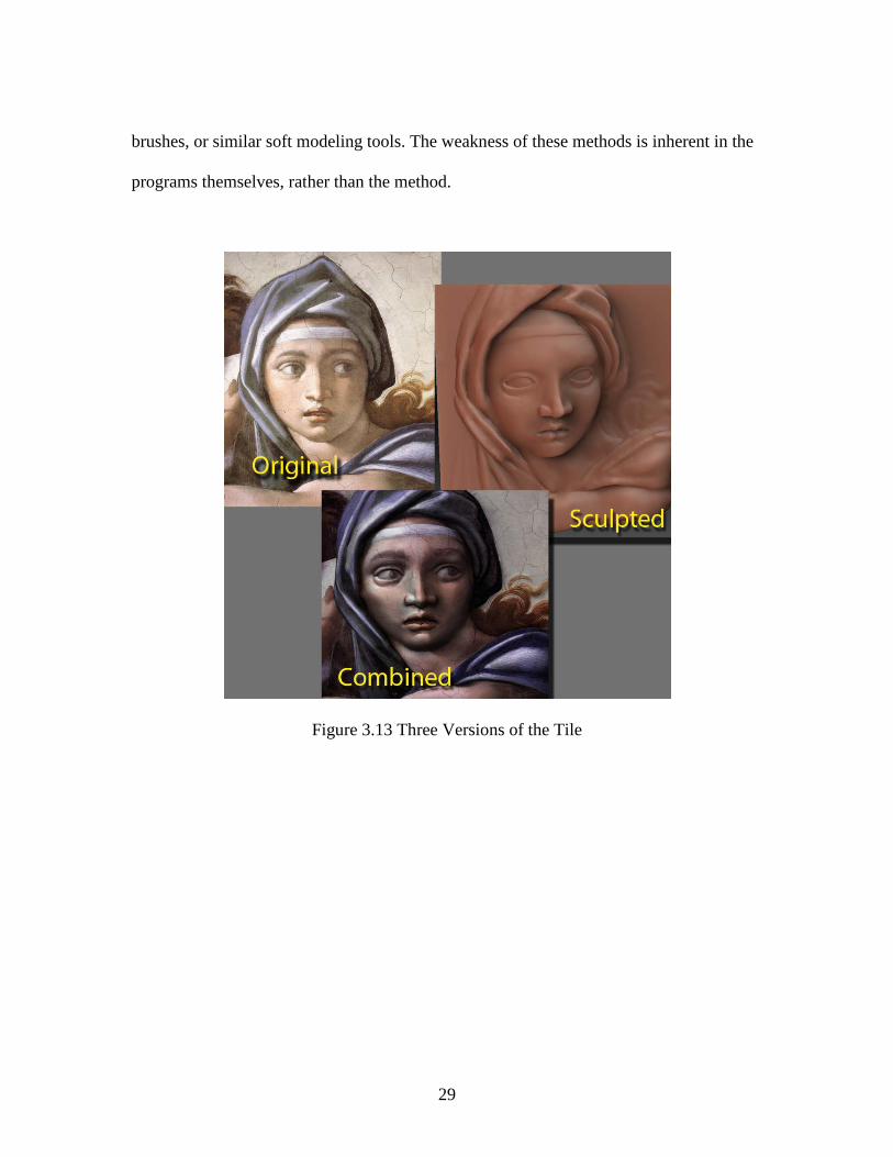
Once the sculpt is complete (Figure 3.12), a variety of processes can be performed
on the sculpture depending on the desired final result. Since the sculpture has a
foundation based on a plane and a two-dimensional image, exporting normal and
displacement maps of the mesh to other programs such as Maya work very well. For this
project, the reapplication of the painting on top of the sculpture yielded an interesting
result (Figure 3.13). A certain sense of life emerges, which is even more apparent when
interacting with the sculpture inside Zbrush.
In conclusion, this technique can produce good results, and while it is not the only
means of creating relief sculptures, it is one of the fastest and most intuitive. A similar
result could be attained through direct polygon modeling or the use of Maya’s artisan
29
brushes, or similar soft modeling tools. The weakness of these methods is inherent in the
programs themselves, rather than the method.
Figure 3.13 Three Versions of the Tile

30
3.4 Creating Digital Impasto with ZBrush
Pixologic’s ZBrush is a program that uses pixol technology instead of pixels. A
pixol is different from a pixel in that it stores lighting, color, material, and depth
information, as well as the (x, y) information on screen. ZBrush grants artists the ability
to sculpt objects in real-time with millions of polygons.
ZBrush also lets the user work on a 2.5D canvas, a feature that set it apart from
other graphics programs at the time of its original release. Advanced three-dimensional
features were later developed which transformed it into an industry standard application.
In order to take full advantage of ZBrush’s capabilities, both the 2.5D and the three-
dimensional versions of digital impasto are demonstrated.
3.4.1 Paint Brush Alpha
Unlike Corel Painter, ZBrush contains a helpful selection of tools for extracting
depth information from a canvas or model. A primary challenge of using ZBrush is
creating the brush tools to produce the effects disired.
Using Corel Painter's brushes as a guide, several brush types can be created for
use in ZBrush. Most paintbrushes vary in two different ways: shape and bristle hardness.
Figure 3.14 shows some of the brush alphas developed for this thesis. Each brush has
uses in different situations, depending on the artistic style.

31
Figure 3.14 Alpha Brushes- Soft Flat, Round Hard, and Soft Round
In ZBrush, round brushes work well in most situations. Round brushes function
whether the brush alpha rotates with the stroke or not. The flat or edged brush, used for
special applications, is thinner than the round and creates specific effects such as angled
strokes and varying thickness of lines. A normal stroke provides detailed bristle
definition because the alpha is made up of numerous vertical lines. When the alpha does
not rotate with the stroke, it creates a different edge when used in the vertical, rather than
in the horizontal, direction.
To replicate the effect of a hard bristle brush, more detailed spotted alphas should
be used. Hard-edged alphas more closely replicate the surface of a hard nylon paintbrush,
which adds detail and surface contrast. High contrast, however, can be a problem since
the added detail can quickly create noise, which in turn can create artifacts in normal and
displacement maps, as well as errors in specularity at render time.
The soft bristle brush is more versatile than the hard style. The simplest way to
produce a soft bristle brush is to blur the alpha from an existing hard bristle brush. The
32
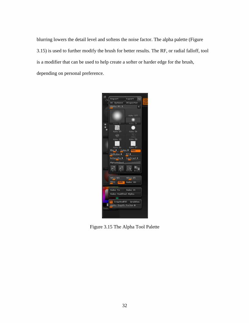
blurring lowers the detail level and softens the noise factor. The alpha palette (Figure
3.15) is used to further modify the brush for better results. The RF, or radial falloff, tool
is a modifier that can be used to help create a softer or harder edge for the brush,
depending on personal preference.
Figure 3.15 The Alpha Tool Palette
33
3.4.2 ZBrush 2.5D Depth Creation
The first method for creating digital impasto involves using the 2.5D toolset in
ZBrush. To prepare the canvas, under Document settings, set the foreground color black,
the background color to black, and the gradient to 0. These settings will preserve an all
black background for use in transparency. If transparency will not be used, use the layer
palette fill option to cover the canvas with the current brush settings.
At this point, the user is ready to paint on the canvas. Three tools that are useful
and similar to brushes in Painter are the paintbrush tool, the smudge tool and the
directional brush tool. The paintbrush tool produces an even stroke of color and depth.
With bristle mode enabled, it lightens the stroke and pushes more contrast out of the
alpha. Since the paintbrush does not roll the alpha, it is useful for creating edged effects
using the flat bristle alpha. The directional brush tool rolls the alpha with the brush
stroke. This tool, with appropriate alpha, tablet, intensity and low Zadd or outward depth
produces results that most closely resemble typical paint strokes. The smudge tool is used
to blend strokes, reduce detail, and control depth flow. The smudge tool is useful when
applied to heavily worked areas to change their direction or look. In addition, the smudge
tool is useful for smoothing out areas of noise in the image.
With most of the tools, a Zadd intensity of 25 or less works best. Even at 25, the
user can easily build up unintended high levels of depth. For most applications where
more accurate paint application is desired, a Zadd intensity of approximately 10 is more
useful. The RGB intensity functions similarly to opacity in Photoshop: the lower the
intensity, the more transparent the stroke. For thick applications a higher Zadd and

34
opaque stroke near 100% should work. If the artistic goal is to produce an effect closer to
a wash, a very low or disabled Zadd, with a 50% or less RGB, is more convincing.
Once the image is completed, the next step is to extract information from the
image for use in another program, such as Maya. The MRGBZGrabber is a tool that
grabs all the material, color and depth information in the image and stores it in the alpha
and texture channels [SPENCER2008]. The shaded RGB option will bake the look of the
image into the texture. If the option is deselected, only the color information is obtained.
The non-shaded option is best for exporting to another application where the image will
be used in a new shader system. The "Both" option creates an image with the bake texture
on the left, and the color image on the right. The combined image can then be loaded in
Photoshop for separation.
Once the canvas or a section of the canvas is selected with the MRGBZGrabber,
new images will appear in the texture and alpha channel. Under the texture panel, the
texture export option will allow the user to save the color of the image, while the alpha
export option will allow the user to save out the depth information.
The final step is to create and export a normal map of the image in ZBrush. First
select paintbrush, then turn on the material channel only, turn off Zadd, and paint over the
image using the normalMRGB shader. The repainted image can exported with the
MRGBZGrabber, or by simply exporting the document.
35
3.4.3 ZBrush 3D Impasto Depth Creation
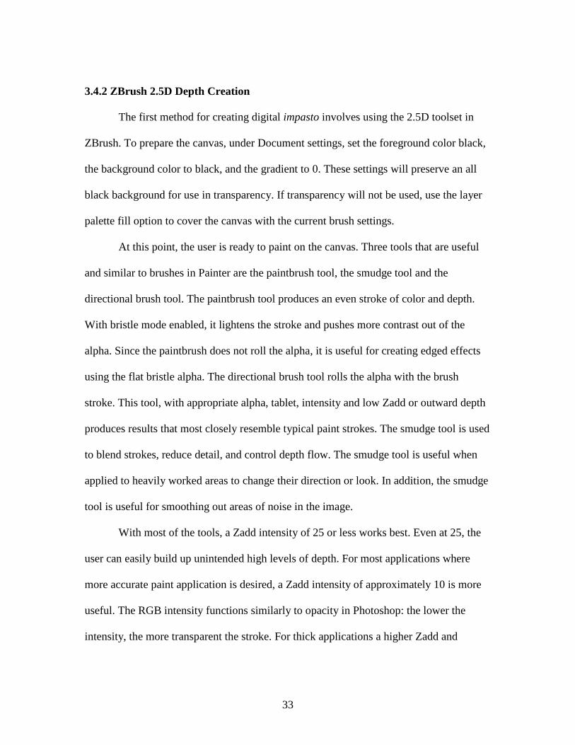
Figure 3.16 ZBrush in 3D Edit mode
The three-dimensional depth creation process allows the user to take full
advantage of ZBrush's three-dimensional sculpting tools (Figure 3.16), which can be
beneficial or constraining depending on the artist's familiarity with the sculpting features
of ZBrush.
The Zplane is a good starting point because it is a power of eight mesh. No matter what
division level is desired for export, the resolution will always create a square image,
whether it is 32x32, or 4096x4096. At seven divisions, a zplane has a resolution of 4.198

36
million polygons, which allows for a 1:1 ratio of polygons to pixels in a 2048x2048
image. One more division results in more than 16 million polygons, which is enough for
a 4096 x 4096 image. The large image resolutions come with some drawbacks, however,
namely processing times and memory usage, in addition to larger file sizes. For example,
a four million polygon zplane, exported from ZBrush in OBJ format is almost 750MB.
Given that Maya does not handle meshes of such high polygon counts, the production
pipeline should avoid using such files. ZBrush's Normal map and texture export options,
however, can provide other options.
To start the process, create a zplane on the canvas. Next, the Make PolyMesh3D
button will convert the ztool into an editable poly object for sculpting on. Enabling
Colorize allows the plane to be painted and ensures that UVs for the object are created for
export later. To save the flatness of this canvas for later use, a morph target will need to
be created so that all the edits to the object can be recorded later onto normal and
displacement maps.
From this point forward, the mesh will act as a canvas that can be sculpted and
painted. Two different approaches can be pursued: the displace canvas approach, and the
paint on canvas approach. The displace canvas approach involves applying the standard
sculpting brushes on the plane, causing it to deform, which gives additional depth to the
image. This approach can be taken to extremes to create relief sculpture. The paint on
canvas method makes use of the new clay brushes included in ZBrush. These brushes
produce a result that is similar to layering media onto the object. The effect is more
subdued, and can be limited more easily than with the standard brush (Figure 3.17).

37
Figure 3.17 ZBrush Painted Zplane in Edit Mode
One issue to note about some of the ZBrush tools concerns linked Zadd and RGB
modifiers. When the two controls are linked, the creation of gel-like effects (high
transparency, high impasto) is much more difficult. Keeping the two controls separate,
however, gives the artist improved control over the desired effects of the brush.
Reducing the resolution of the completed image will reduce the high frequency
noise, while leaving large areas of depth still present. An alternate approach is to employ
the saved morph target of the original plane to create a normal map containing all the
sculptural modifications.

38
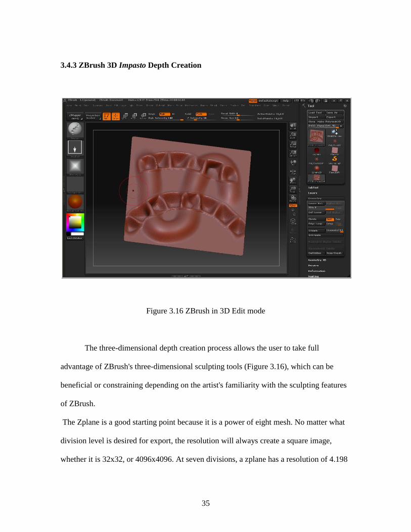
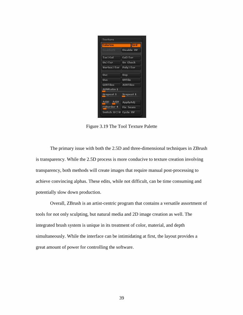
Figure 3.18 The ZMapper Interface
ZBrush contains a plug-in tool called ZMapper (Figure 3.18), which is used for
the creation of normal and cavity maps. ZMapper contains a plethora of options for
creating such maps, but the defaults suffice for the current task. The application generates
a normal map of the current object and saves it to the Texture palette (Figure 3.19), ready
for export. Once exported from ZBrush, the normal map must be taken into Photoshop
and inverted before it is ready for use in Maya. To extract the color information from the
object, the Col>Txr option saves the color information out to the Texture palette, where
it can be exported from ZBrush.
39
Figure 3.19 The Tool Texture Palette
The primary issue with both the 2.5D and three-dimensional techniques in ZBrush
is transparency. While the 2.5D process is more conducive to texture creation involving
transparency, both methods will create images that require manual post-processing to
achieve convincing alphas. These edits, while not difficult, can be time consuming and
potentially slow down production.
Overall, ZBrush is an artist-centric program that contains a versatile assortment of
tools for not only sculpting, but natural media and 2D image creation as well. The
integrated brush system is unique in its treatment of color, material, and depth
simultaneously. While the interface can be intimidating at first, the layout provides a
great amount of power for controlling the software.

40
CHAPTER FOUR
SCHILDERMENNEKE: A CASE STUDY
The techniques presented in this thesis began during production of the animated
short Schildermenneke. Inspired by the works and letters of Vincent van Gogh, the
animation attempts to capture the nature of several of van Gogh's paintings using a
combination of two and three-dimensional effects.
Schildermenneke gives the viewer a sense of being close to the artist’s canvas,
but also attempts to bring life and motion into otherwise still images. The piece is a
tribute to the artist’s life and works, and at the same time, an exploration of how current
digital media can be used to reinterpret artwork produced over a century ago.
The animation began as a way to create narrative for a sequence of paintings tied
together not only through visual action, but through dialogue as well. During research of
the life of van Gogh, several quotations of the painter were identified and extracted for
use in the narration. The book, Dear Theo, which contains a multitude of van Gogh's
letters to his brother, was the primary source of information. A violinist provided a
soundtrack and original score for the animation.
The film uses works created during his time in Arles—the period of his greatest
productivity and his most well known style. In an attempt to create an original
environment that maintains the spirit of his paintings, various elements from multiple
works were combined to generate a single cohesive montage. Different techniques from
various software packages were then used to give the work a style similar to that of van

41
Gogh. The geography captured in several of his paintings was modeled in Maya to
transform the canvas into a three-dimensional environment, while a combination of
foreshortening and long camera angles attempt to imitate van Gogh’s unique sense of
perspective.
In order to capture the appearance of thick raised paint on a canvas surface, most
of the textures were created using Corel Painter X with unique brush settings designed to
mimic van Gogh’s style. The majority of the normal maps for the textures were created
using Painter impasto effects combined with image editing techniques in Photoshop, as
discussed in Chapter 3. Maya paint effects were also incorporated to give foliage a
painted appearance as well as provide subtle movement.
Several MEL scripts were written to simulate wind blowing through a field of
wheat. The controls of the script can be adjusted to vary the strength, direction, and
frequency of each wind gust as well as the individual movement of each stalk within the
field. Two-dimensional effects, such as cell animation with adaptive blending techniques,
were used to simulate an animation style that appears to have a painted quality.
The animation consists of four three-dimensional scenes tied together through a
combination of lighting and post-processing effects. Autodesk Maya was used for the
three-dimensional graphics. The compositing and post processes were completed using
Apple Shake. Additional graphics tasks were completed with Adobe Photoshop , Corel
Painter, and CrazyBump.

42
The animation uses four primary three-dimensional sets: the dawn over the town,
the harvester, the wheat fields, and the harbor. The main actor in each scene is the
camera, which is manually key framed .
The dawn scene was modeled and textured using the camera projection process.
Additional details were created from Maya paint effects and traditional cell animation.
The scene was rendered in separate layers: the background, the buildings, the mid-ground
plane, the paint effects bushes, and the foreground bush. The separate layers were then
composited together with the traditional animation to produce the final shot (Figure 4.1).

43
Figure 4.1 View and Lighting Transition of the Dawn Scene

44
The harvester scene (Figure 4.2) was constructed similarly to the dawn shot using
camera projection. The textures, however, were created as new elements using reference
paintings (Figure 4.3). The textures were created in Corel Painter, followed by the depth
extraction process to produce normal maps, which helped to enhance the impasto effect
of the textures. The characters and background were animated by hand (Figure 4.4),
while the wheat field was animated by a MEL script using a lattice.
Figure 4.2 The Completed Harvest Scene

45
Figure 4.3 The Color and Normal Map Textures for the Harvest
Figure 4.4 Still Frames of the Hand-Animated Elements used in the Harvest Scene

46
The third scene was created similarly to the previous harvester scene. The
geometry was modeled from the image (Figure 4.5), and adapted to fit the widescreen
format. The background sky was painted in Corel Painter and animated through Apple
Shake with the adaptive blend setting (Figure 4.6). The flames were created in Maya,
while the hand-animated birds were composited using Shake (Figure 4.7).
Figure 4.5 The Wireframe and Textured Model of the Crows Scene

47
Figure 4.6 Still Frame from the Hand Animated Sky
Figure 4.7 Crows Transition Frames

48
The final scene of the animation was modeled in the same way as the others, but
special consideration was taken in order for the camera zoom to function as desired, and
the water shader to interact properly with its surface plane (Figure 4.8). The texturing
process used a combination of Adobe Photoshop editing techniques and image map
creation in Corel Painter. Normal maps were then created and applied to provide a better
surface quality to the geometry. A normal map was later applied to the water shader in
order to replicate a pool of paint (Figure 4.9). The couple in the scene was traditionally
animated, and tracked using Apple Shake. The glow of the stars and other lighting
effects were created in Maya using light effects (Figure 4.10).
Figure 4.8 Top and Side View of the Final Scene

49
Figure 4.9 The Original and Normal Mapped Water
Figure 4.10 Composited Elements of the Night Sky
50
CHAPTER FIVE
CONCLUSION
In this thesis, several techniques were presented for recreating and enhancing two-
dimensional images using three-dimensional graphics technologies. While these concepts
were explored using a limited array of software applications, they can be adopted for
most graphics software. As long as the fundamental elements of color, depth, and light
can be manipulated, these techniques should remain viable.
While the techniques in this thesis are intended for use as ways to bring 2D
imagery into the third dimension, they are not limited to this application. The techniques
can be used not only for texture applications in shader systems, but also in the areas of
photo manipulation. The techniques could also be used to create sculpting aids as well as
background and matte work.
For future work more brushes can be developed to more accurately replicate the
effects of a wide array of traditional paint brushes. More surface materials could also be
developed to more realistically simulate the quality of light on paint. Further, additional
techniques can be developed to incorporate the creation and blending of occlusion maps
into the textures, as well as modification of the generated normal and displacement maps.
Finally, techniques can be developed that would allow for natural media texturing of
sculptured objects, breaking from the mold of flat planer objects and pushing into the
area of organic and figurative models.
Over the course of the techniques explored in this work, several opportunities for
future development were discovered. One opportunity is the Paint Stop plug-in for

51
ZBrush, which adds much improved tools for natural media creation. While Paint Stop
does adds tools for creating digital impasto using the 2.5D process outlined in this thesis,
the tools are not yet transferable to the three-dimensional process in a meaningful way.
These new tools, coupled with Zbrush’s ability to easily export the depth and color
information, may give it a competitive advantage over Corel Painter.
In the case of Schildermenneke, several areas of the animation could be improved.
First, the textures could have used more refinement and the geometry more depth and
detail. Another area of improvement involves asset management. Having multiple scenes
linked over large numbers of frames, composed of several layers with post effects applied
on top, was a challenge for the team. During the production of Schildermenneke, no
single program or single process was able to create the visuals of the animation. The final
product was completed only through a combination of numerous tools and developed
techniques. The processes and techniques outlined in this thesis will enable content
creators more tools in pursuit of traditional art methods. While the digital will never
replace the physical, each development brings the computer ever closer.
52
APENDIX A
PAINTER DEPTH CREATION PROCESS
The process for creating a painted image for later use as a texture map is as follows:
1. Create an image to desired specifications,
2. Change the layer to Gel mode.
3. Create a new layer.
4. Fill it black and place under the gel layer. The gel layer will be used to create the
alpha mask for transparency.
Now the canvas is ready to paint. Use the Impasto brush (Figure A.1), or any
other brush that creates depth to create the image or texture desired. Additional layers can
be created on top of the black background plate. For some situations, using a depth only
brush can create the desired effect, without destroying already established color
information.

53
Figure A.1 The Impasto Brush Settings
Once the image is complete, open the Surface Lighting Options (Figure A.2).
Before changing any settings, move the light to the top position and change the
applicable lighting settings to
Amount 100%
Picture 100%
Shine 0%
Reflection 0%
Brightness 1.00
Conc 0.00
Exposure 1.41

54
Figure A.2 The Surface Lighting Box
These settings will display the depth information of the image. Once done, close
the options window and save the image out as a jpg (Figure A.3). Make sure to use a
good naming convention to prevent confusion of the images. It is important to know
which image has light coming from which direction. Change the light position and save
out an image for left. Repeat for the right and bottom. Finally move the light to the
middle of the sphere, change the layer to normal and uncheck the enable impasto box
under Surface Lighting. The lack of impasto will display a flat color map. Save the
image if color information is also needed.

55
Figure A.3 The Exported Top Image
The next steps are performed using Adobe Photoshop. These steps convert the
depth information into data that the normal map will later use for displacing in the X and
Y directions.
1. Create two images of the same dimensions as the grey impasto images. They
should be RGB 8-bit images.
2. Load in all four of the depth images.

56
3. Select the image that was saved from the top light position. highlight the Green
channel, and copy–paste the image into one of the new blank images.
4. Go to the left image, and copy-paste the red channel into the same blank image as
the top. With the new image containing the top and left images selected, flatten
the image, go to adjust levels, and set the range to 127-0 (Figure A.4).
5. For the second blank image, copy in the bottom image green channel, and the
right image red channel, then flatten and set the levels to 128-255.
Figure A.4 The Levels Options Box
6. Paste the second new image into the first, and set its layer to overlay and flatten
the image.

57
7. Select the blue channel, and fill with a mid-blue. The settings (146,146,255)-
(174,174,255) work well. The difference in the colors mainly affects the intensity
of the map on the z-axis.
The normal map is now complete. Simply save it out with the layers merged.
The Color map can be modified until the image is only black. Save the image separately
for use as an alpha map or specular map.
The next step, although optional, is to load the normal and color images into
Crazy Bump for additional tweaking with its real-time updates, as well as creation of
specularity and occlusion maps. Regardless, the normal map can be used in Maya and the
intensity of the effect can also be adjusted.
Figure A.5 The Color, Alpha, and Normal Maps

58
Once completed, the images can be loaded into a shader in Maya (Figure A.5). Be
sure to select the option to "use tangent space normals" under the bump map options to
properly use the normal map (Figure A.6).
Figure A.6 The Texture Rendered on a Plane

59
REFERENCES
[BIRN2006] Birn, J. (2006). Digital Lighting and Rendering, Second Edition. Berkeley, California: New Riders.
[CLARK2007] Clark, R. (2007, june 22). Normal Map Photography. Retrieved Febuary 3, 2008, from ZARRIA.NET: http://zarria.net/nrmphoto/nrmphoto.html
[JANSON1964] Janson, H. W. (1964). History of Art. New York: Harry N. Abrams Inc.
[LANIER2006] Lanier, L. (2006). Advanced Maya Texturing and Lighting. Indianapolis, Indiana: Wiley Publishing Inc.
[LANTERI1985] Lanteri, E. (1985). Modelling and Sculpting the Human Figure. Mineola, New York: Dover Publications Inc.
[SPENCER2008] Spencer, S. (2008). ZBrush Character Creation: Advanced Digital Sculpting. Indianapolis, Indiana: Wiley Publishing.
[PREBLES2009] Prebles, Frank. (2009). Prebles' Artforms.Upper Saddle River, New Jersey, Pearson Education Ltd.
[POZZO1685] Apotheosis of St. Ignactius, 1685, by Andrea Pozzo, fresco, church of Sant'Ignazio, Rome. Source: http://flickr.com/photos/antmoose/62278449/ [CASO1874] Escaping Criticism, 1874, by Pere Borrell del Caso, oil on canvas, Banco de España, Madrid. [AUERBACK1952] Summer Building Site, 1952, Fank Auerback, Source http://www.courtauld.ac.uk