im883-a vantage 400 - lincoln · pdf filevantage 400 operator’s manual im883-a april,...
TRANSCRIPT
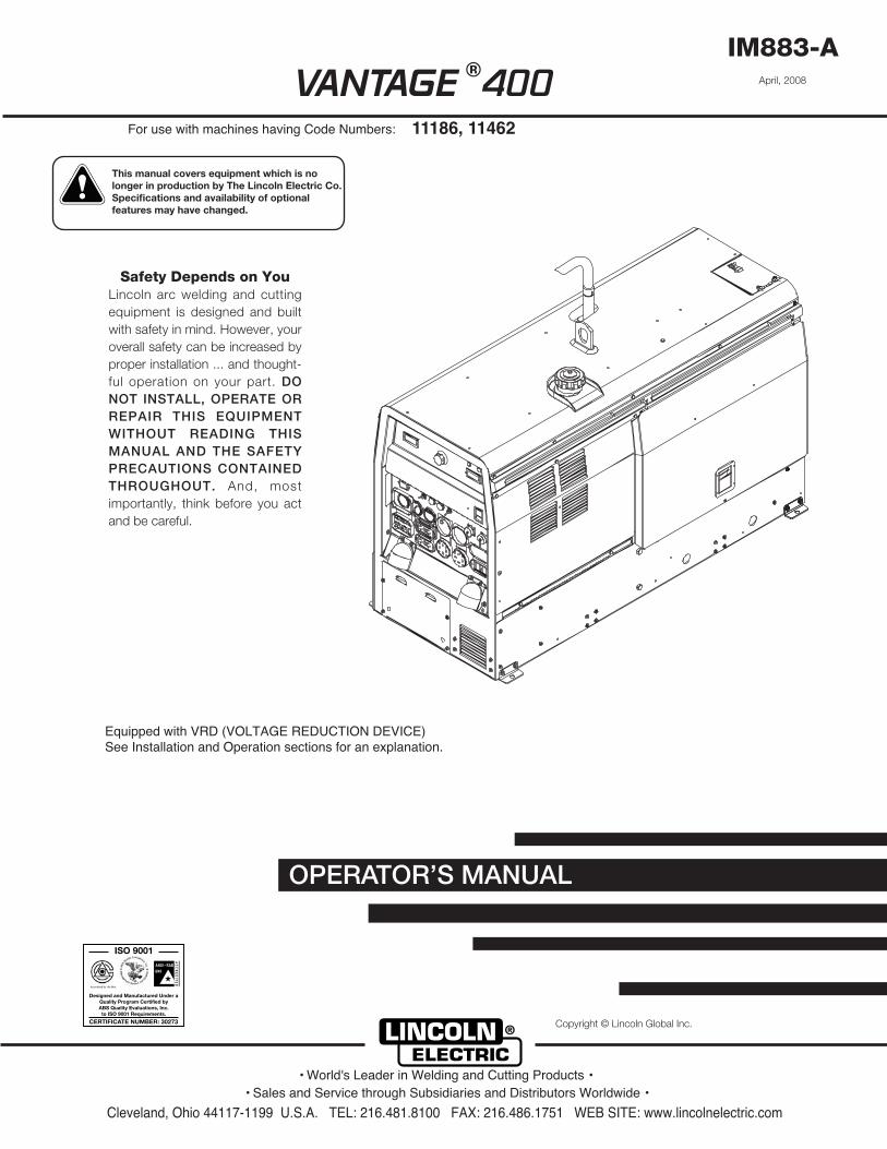
VANTAGE 400
OPERATOR’S MANUAL
IM883-AApril, 2008
Safety Depends on YouLincoln arc welding and cuttingequipment is designed and builtwith safety in mind. However, youroverall safety can be increased byproper installation ... and thought-ful operation on your part. DONOT INSTALL, OPERATE ORREPAIR THIS EQUIPMENTWITHOUT READING THISMANUAL AND THE SAFETYPRECAUTIONS CONTAINEDTHROUGHOUT. And, mostimportantly, think before you actand be careful.
For use with machines having Code Numbers:
Equipped with VRD (VOLTAGE REDUCTION DEVICE)See Installation and Operation sections for an explanation.
11186, 11462
• Sales and Service through Subsidiaries and Distributors Worldwide •
Cleveland, Ohio 44117-1199 U.S.A. TEL: 216.481.8100 FAX: 216.486.1751 WEB SITE: www.lincolnelectric.com
• World's Leader in Welding and Cutting Products •
Copyright © Lincoln Global Inc.
®
This manual covers equipment which is no longer in production by The Lincoln Electric Co. Speci�cations and availability of optional features may have changed.
FOR ENGINEpowered equipment.
1.a. Turn the engine off before troubleshooting and maintenancework unless the maintenance work requires it to be running.
____________________________________________________1.b. Operate engines in open, well-ventilated
areas or vent the engine exhaust fumesoutdoors.
____________________________________________________1.c. Do not add the fuel near an open flame
welding arc or when the engine is running.Stop the engine and allow it to cool beforerefueling to prevent spilled fuel from vaporiz-ing on contact with hot engine parts andigniting. Do not spill fuel when filling tank. Iffuel is spilled, wipe it up and do not startengine until fumes have been eliminated.
____________________________________________________1.d. Keep all equipment safety guards, covers and devices in
position and in good repair.Keep hands, hair, clothing andtools away from V-belts, gears, fans and all other movingparts when starting, operating or repairing equipment.
____________________________________________________
1.e. In some cases it may be necessary to remove safetyguards to perform required maintenance. Removeguards only when necessary and replace them when themaintenance requiring their removal is complete.Always use the greatest care when working near movingparts.
___________________________________________________1.f. Do not put your hands near the engine fan.
Do not attempt to override the governor oridler by pushing on the throttle control rodswhile the engine is running.
___________________________________________________1.g. To prevent accidentally starting gasoline engines while
turning the engine or welding generator during maintenancework, disconnect the spark plug wires, distributor cap ormagneto wire as appropriate.
iSAFETYi
ARC WELDING CAN BE HAZARDOUS. PROTECT YOURSELF AND OTHERS FROM POSSIBLE SERIOUS INJURY OR DEATH.KEEP CHILDREN AWAY. PACEMAKER WEARERS SHOULD CONSULT WITH THEIR DOCTOR BEFORE OPERATING.
Read and understand the following safety highlights. For additional safety information, it is strongly recommended that youpurchase a copy of “Safety in Welding & Cutting - ANSI Standard Z49.1” from the American Welding Society, P.O. Box351040, Miami, Florida 33135 or CSA Standard W117.2-1974. A Free copy of “Arc Welding Safety” booklet E205 is availablefrom the Lincoln Electric Company, 22801 St. Clair Avenue, Cleveland, Ohio 44117-1199.
BE SURE THAT ALL INSTALLATION, OPERATION, MAINTENANCE AND REPAIR PROCEDURES AREPERFORMED ONLY BY QUALIFIED INDIVIDUALS.
WARNING
Mar ʻ95
ELECTRIC ANDMAGNETIC FIELDSmay be dangerous
2.a. Electric current flowing through any conductor causeslocalized Electric and Magnetic Fields (EMF). Weldingcurrent creates EMF fields around welding cables andwelding machines
2.b. EMF fields may interfere with some pacemakers, andwelders having a pacemaker should consult their physicianbefore welding.
2.c. Exposure to EMF fields in welding may have other healtheffects which are now not known.
2.d. All welders should use the following procedures in order tominimize exposure to EMF fields from the welding circuit:
2.d.1. Route the electrode and work cables together - Securethem with tape when possible.
2.d.2. Never coil the electrode lead around your body.
2.d.3. Do not place your body between the electrode andwork cables. If the electrode cable is on your rightside, the work cable should also be on your right side.
2.d.4. Connect the work cable to the workpiece as close aspossible to the area being welded.
2.d.5. Do not work next to welding power source.
1.h. To avoid scalding, do not remove theradiator pressure cap when the engine ishot.
CALIFORNIA PROPOSITION 65 WARNINGS
Diesel engine exhaust and some of its constituentsare known to the State of California to cause can-cer, birth defects, and other reproductive harm.
The engine exhaust from this product containschemicals known to the State of California to causecancer, birth defects, or other reproductive harm.
The Above For Diesel Engines The Above For Gasoline Engines

iiSAFETYii
ARC RAYS can burn.4.a. Use a shield with the proper filter and cover
plates to protect your eyes from sparks andthe rays of the arc when welding or observingopen arc welding. Headshield and filter lensshould conform to ANSI Z87. I standards.
4.b. Use suitable clothing made from durable flame-resistantmaterial to protect your skin and that of your helpers fromthe arc rays.
4.c. Protect other nearby personnel with suitable, non-flammablescreening and/or warn them not to watch the arc nor exposethemselves to the arc rays or to hot spatter or metal.
ELECTRIC SHOCK cankill.3.a. The electrode and work (or ground) circuits
are electrically “hot” when the welder is on.Do not touch these “hot” parts with your bareskin or wet clothing. Wear dry, hole-free
gloves to insulate hands.
3.b. Insulate yourself from work and ground using dry insulation.Make certain the insulation is large enough to cover your fullarea of physical contact with work and ground.
In addition to the normal safety precautions, if weldingmust be performed under electrically hazardousconditions (in damp locations or while wearing wetclothing; on metal structures such as floors, gratings orscaffolds; when in cramped positions such as sitting,kneeling or lying, if there is a high risk of unavoidable oraccidental contact with the workpiece or ground) usethe following equipment:
• Semiautomatic DC Constant Voltage (Wire) Welder.• DC Manual (Stick) Welder.• AC Welder with Reduced Voltage Control.
3.c. In semiautomatic or automatic wire welding, the electrode,electrode reel, welding head, nozzle or semiautomaticwelding gun are also electrically “hot”.
3.d. Always be sure the work cable makes a good electricalconnection with the metal being welded. The connectionshould be as close as possible to the area being welded.
3.e. Ground the work or metal to be welded to a good electrical(earth) ground.
3.f. Maintain the electrode holder, work clamp, welding cable andwelding machine in good, safe operating condition. Replacedamaged insulation.
3.g. Never dip the electrode in water for cooling.
3.h. Never simultaneously touch electrically “hot” parts ofelectrode holders connected to two welders because voltagebetween the two can be the total of the open circuit voltageof both welders.
3.i. When working above floor level, use a safety belt to protectyourself from a fall should you get a shock.
3.j. Also see Items 6.c. and 8.
FUMES AND GASEScan be dangerous.5.a. Welding may produce fumes and gases
hazardous to health. Avoid breathing thesefumes and gases. When welding, keepyour head out of the fume. Use enoughventilation and/or exhaust at the arc to keep
fumes and gases away from the breathing zone. Whenwelding with electrodes which require specialventilation such as stainless or hard facing (seeinstructions on container or MSDS) or on lead orcadmium plated steel and other metals or coatingswhich produce highly toxic fumes, keep exposure aslow as possible and below Threshold Limit Values (TLV)using local exhaust or mechanical ventilation. Inconfined spaces or in some circumstances, outdoors, arespirator may be required. Additional precautions arealso required when welding on galvanized steel.
5. b. The operation of welding fume control equipment is affectedby various factors including proper use and positioning ofthe equipment, maintenance of the equipment and the spe-cific welding procedure and application involved. Workerexposure level should be checked upon installation andperiodically thereafter to be certain it is within applicableOSHA PEL and ACGIH TLV limits.
5.c. Do not weld in locations near chlorinated hydrocarbon vaporscoming from degreasing, cleaning or spraying operations.The heat and rays of the arc can react with solvent vapors toform phosgene, a highly toxic gas, and other irritating prod-ucts.
5.d. Shielding gases used for arc welding can displace air andcause injury or death. Always use enough ventilation,especially in confined areas, to insure breathing air is safe.
5.e. Read and understand the manufacturerʼs instructions for thisequipment and the consumables to be used, including thematerial safety data sheet (MSDS) and follow youremployerʼs safety practices. MSDS forms are available fromyour welding distributor or from the manufacturer.
5.f. Also see item 1.b.
AUG 06

iiiSAFETYiii
FOR ELECTRICALLYpowered equipment.
8.a. Turn off input power using the disconnectswitch at the fuse box before working onthe equipment.
8.b. Install equipment in accordance with the U.S. NationalElectrical Code, all local codes and the manufacturerʼsrecommendations.
8.c. Ground the equipment in accordance with the U.S. NationalElectrical Code and the manufacturerʼs recommendations.
CYLINDER may explodeif damaged.7.a. Use only compressed gas cylinders
containing the correct shielding gas for theprocess used and properly operatingregulators designed for the gas and
pressure used. All hoses, fittings, etc. should be suitable forthe application and maintained in good condition.
7.b. Always keep cylinders in an upright position securelychained to an undercarriage or fixed support.
7.c. Cylinders should be located:• Away from areas where they may be struck or subjected tophysical damage.
• A safe distance from arc welding or cutting operations andany other source of heat, sparks, or flame.
7.d. Never allow the electrode, electrode holder or any otherelectrically “hot” parts to touch a cylinder.
7.e. Keep your head and face away from the cylinder valve outletwhen opening the cylinder valve.
7.f. Valve protection caps should always be in place and handtight except when the cylinder is in use or connected foruse.
7.g. Read and follow the instructions on compressed gascylinders, associated equipment, and CGA publication P-l,“Precautions for Safe Handling of Compressed Gases inCylinders,” available from the Compressed Gas Association1235 Jefferson Davis Highway, Arlington, VA 22202.
Jan, 07
WELDING and CUTTINGSPARKS cancause fire or explosion.6.a. Remove fire hazards from the welding area.
If this is not possible, cover them to preventthe welding sparks from starting a fire.
Remember that welding sparks and hotmaterials from welding can easily go through small cracksand openings to adjacent areas. Avoid welding nearhydraulic lines. Have a fire extinguisher readily available.
6.b. Where compressed gases are to be used at the job site,special precautions should be used to prevent hazardoussituations. Refer to “Safety in Welding and Cutting” (ANSIStandard Z49.1) and the operating information for theequipment being used.
6.c. When not welding, make certain no part of the electrodecircuit is touching the work or ground. Accidental contactcan cause overheating and create a fire hazard.
6.d. Do not heat, cut or weld tanks, drums or containers until theproper steps have been taken to insure that such procedureswill not cause flammable or toxic vapors from substancesinside. They can cause an explosion even though they havebeen “cleaned”. For information, purchase “RecommendedSafe Practices for the Preparation for Welding and Cutting ofContainers and Piping That Have Held HazardousSubstances”, AWS F4.1 from the American Welding Society(see address above).
6.e. Vent hollow castings or containers before heating, cutting orwelding. They may explode.
6.f. Sparks and spatter are thrown from the welding arc. Wear oilfree protective garments such as leather gloves, heavy shirt,cuffless trousers, high shoes and a cap over your hair. Wearear plugs when welding out of position or in confined places.Always wear safety glasses with side shields when in awelding area.
6.g. Connect the work cable to the work as close to the weldingarea as practical. Work cables connected to the buildingframework or other locations away from the welding areaincrease the possibility of the welding current passingthrough lifting chains, crane cables or other alternate cir-cuits. This can create fire hazards or overheat lifting chainsor cables until they fail.
6.h. Also see item 1.c.
6.I. Read and follow NFPA 51B “ Standard for Fire PreventionDuring Welding, Cutting and Other Hot Work”, availablefrom NFPA, 1 Batterymarch Park,PO box 9101, Quincy, Ma022690-9101.
6.j. Do not use a welding power source for pipe thawing.

ivSAFETYiv
Mar. ʻ93
PRÉCAUTIONS DE SÛRETÉPour votre propre protection lire et observer toutes les instructionset les précautions de sûreté specifiques qui parraissent dans cemanuel aussi bien que les précautions de sûreté générales suiv-antes:
Sûreté Pour Soudage A LʼArc1. Protegez-vous contre la secousse électrique:
a. Les circuits à lʼélectrode et à la piéce sont sous tensionquand la machine à souder est en marche. Eviter toujourstout contact entre les parties sous tension et la peau nueou les vétements mouillés. Porter des gants secs et sanstrous pour isoler les mains.
b. Faire trés attention de bien sʼisoler de la masse quand onsoude dans des endroits humides, ou sur un planchermetallique ou des grilles metalliques, principalement dansles positions assis ou couché pour lesquelles une grandepartie du corps peut être en contact avec la masse.
c. Maintenir le porte-électrode, la pince de masse, le câblede soudage et la machine à souder en bon et sûr étatdefonctionnement.
d.Ne jamais plonger le porte-électrode dans lʼeau pour lerefroidir.
e. Ne jamais toucher simultanément les parties sous tensiondes porte-électrodes connectés à deux machines à souderparce que la tension entre les deux pinces peut être letotal de la tension à vide des deux machines.
f. Si on utilise la machine à souder comme une source decourant pour soudage semi-automatique, ces precautionspour le porte-électrode sʼapplicuent aussi au pistolet desoudage.
2. Dans le cas de travail au dessus du niveau du sol, se protégercontre les chutes dans le cas ou on recoit un choc. Ne jamaisenrouler le câble-électrode autour de nʼimporte quelle partiedu corps.
3. Un coup dʼarc peut être plus sévère quʼun coup de soliel,donc:
a. Utiliser un bon masque avec un verre filtrant appropriéainsi quʼun verre blanc afin de se protéger les yeux du ray-onnement de lʼarc et des projections quand on soude ouquand on regarde lʼarc.
b. Porter des vêtements convenables afin de protéger lapeau de soudeur et des aides contre le rayonnement delʻarc.
c. Protéger lʼautre personnel travaillant à proximité ausoudage à lʼaide dʼécrans appropriés et non-inflammables.
4. Des gouttes de laitier en fusion sont émises de lʼarc desoudage. Se protéger avec des vêtements de protection libresde lʼhuile, tels que les gants en cuir, chemise épaisse, pan-talons sans revers, et chaussures montantes.
5. Toujours porter des lunettes de sécurité dans la zone desoudage. Utiliser des lunettes avec écrans lateraux dans leszones où lʼon pique le laitier.
6. Eloigner les matériaux inflammables ou les recouvrir afin deprévenir tout risque dʼincendie dû aux étincelles.
7. Quand on ne soude pas, poser la pince à une endroit isolé dela masse. Un court-circuit accidental peut provoquer unéchauffement et un risque dʼincendie.
8. Sʼassurer que la masse est connectée le plus prés possiblede la zone de travail quʼil est pratique de le faire. Si on placela masse sur la charpente de la construction ou dʼautresendroits éloignés de la zone de travail, on augmente le risquede voir passer le courant de soudage par les chaines de lev-age, câbles de grue, ou autres circuits. Cela peut provoquerdes risques dʼincendie ou dʼechauffement des chaines et descâbles jusquʼà ce quʼils se rompent.
9. Assurer une ventilation suffisante dans la zone de soudage.Ceci est particuliérement important pour le soudage de tôlesgalvanisées plombées, ou cadmiées ou tout autre métal quiproduit des fumeés toxiques.
10. Ne pas souder en présence de vapeurs de chlore provenantdʼopérations de dégraissage, nettoyage ou pistolage. Lachaleur ou les rayons de lʼarc peuvent réagir avec les vapeursdu solvant pour produire du phosgéne (gas fortement toxique)ou autres produits irritants.
11. Pour obtenir de plus amples renseignements sur la sûreté,voir le code “Code for safety in welding and cutting” CSAStandard W 117.2-1974.
PRÉCAUTIONS DE SÛRETÉ POURLES MACHINES À SOUDER ÀTRANSFORMATEUR ET ÀREDRESSEUR
1. Relier à la terre le chassis du poste conformement au code delʼélectricité et aux recommendations du fabricant. Le dispositifde montage ou la piece à souder doit être branché à unebonne mise à la terre.
2. Autant que possible, Iʼinstallation et lʼentretien du poste seronteffectués par un électricien qualifié.
3. Avant de faires des travaux à lʼinterieur de poste, la debranch-er à lʼinterrupteur à la boite de fusibles.
4. Garder tous les couvercles et dispositifs de sûreté à leurplace.

vv
Thank You for selecting a QUALITY product by Lincoln Electric. We want youto take pride in operating this Lincoln Electric Company product••• as much pride as we have in bringing this product to you!
Read this Operators Manual completely before attempting to use this equipment. Save this manual and keep ithandy for quick reference. Pay particular attention to the safety instructions we have provided for your protection.The level of seriousness to be applied to each is explained below:
WARNINGThis statement appears where the information must be followed exactly to avoid serious personal injury or loss of life.
This statement appears where the information must be followed to avoid minor personal injury or damage to this equipment.
CAUTION
Please Examine Carton and Equipment For Damage ImmediatelyWhen this equipment is shipped, title passes to the purchaser upon receipt by the carrier. Consequently, Claimsfor material damaged in shipment must be made by the purchaser against the transportation company at thetime the shipment is received.
Please record your equipment identification information below for future reference. This information can befound on your machine nameplate.
Product _________________________________________________________________________________
Model Number ___________________________________________________________________________
Code Number or Date Code_________________________________________________________________
Serial Number____________________________________________________________________________
Date Purchased___________________________________________________________________________
Where Purchased_________________________________________________________________________
Whenever you request replacement parts or information on this equipment, always supply the information youhave recorded above. The code number is especially important when identifying the correct replacement parts.
On-Line Product Registration- Register your machine with Lincoln Electric either via fax or over the Internet.
• For faxing: Complete the form on the back of the warranty statement included in the literature packetaccompanying this machine and fax the form per the instructions printed on it.
• For On-Line Registration: Go to our WEB SITE at www.lincolnelectric.com. Choose “Quick Links” and then“Product Registration”. Please complete the form and submit your registration.
CUSTOMER ASSISTANCE POLICYThe business of The Lincoln Electric Company is manufacturing and selling high quality welding equipment, consumables, and cutting equip-ment. Our challenge is to meet the needs of our customers and to exceed their expectations. On occasion, purchasers may ask LincolnElectric for advice or information about their use of our products. We respond to our customers based on the best information in our posses-sion at that time. Lincoln Electric is not in a position to warrant or guarantee such advice, and assumes no liability, with respect to such infor-mation or advice. We expressly disclaim any warranty of any kind, including any warranty of fitness for any customerʼs particular purpose,with respect to such information or advice. As a matter of practical consideration, we also cannot assume any responsibility for updating orcorrecting any such information or advice once it has been given, nor does the provision of information or advice create, expand or alter anywarranty with respect to the sale of our products.
Lincoln Electric is a responsive manufacturer, but the selection and use of specific products sold by Lincoln Electric is solely within the controlof, and remains the sole responsibility of the customer. Many variables beyond the control of Lincoln Electric affect the results obtained inapplying these types of fabrication methods and service requirements.
Subject to Change – This information is accurate to the best of our knowledge at the time of printing. Please refer to www.lincolnelectric.comfor any updated information.

vi vi TABLE OF CONTENTSPage
Installation.......................................................................................................................Section ATechnical Specifications.......................................................................................................A-1
Safety Precautions ........................................................................................................A-2VRD (Voltage Reduction Device) ..................................................................................A-2Location and Ventilation................................................................................................A-2Stacking ........................................................................................................................A-2Angle of Operation ........................................................................................................A-2Lifting.............................................................................................................................A-2High Altitude Operation .................................................................................................A-3High Temperature Operation ........................................................................................A-3Cold Weather Operation ...............................................................................................A-3Towing...........................................................................................................................A-3Vehicle Mounting...........................................................................................................A-3
Pre-Operation Engine Service..............................................................................................A-3Oil ..................................................................................................................................A-4Fuel ...............................................................................................................................A-4Engine Coolant..............................................................................................................A-4Battery Connections......................................................................................................A-4Muffler Outlet Pipe ........................................................................................................A-4Spark Arrester ...............................................................................................................A-4Remote Control .............................................................................................................A-4
Electrical Connections..........................................................................................................A-5Machine Grounding.......................................................................................................A-5Welding Terminals ........................................................................................................A-5Welding Output Cables .................................................................................................A-5Cable Installation...........................................................................................................A-5
Auxiliary Power Receptacles and Plugs...............................................................................A-6Standby Power Connections ................................................................................................A-6Premises Wiring ...................................................................................................................A-7Connection of Lincoln Electric Wire Feeders.................................................................A-8,A-9
________________________________________________________________________________
Operation.........................................................................................................................Section BSafety Precautions ..............................................................................................................B-1General Description..............................................................................................................B-1For Auxiliary Power ..............................................................................................................B-1Engine Operation..................................................................................................................B-1Add Fuel ...............................................................................................................................B-1 Break in Period.....................................................................................................................B-1Welder Controls .............................................................................................................B-2,B-3Engine Controls....................................................................................................................B-4
Starting and Stopping the Engine .................................................................................B-4Fuel Consumption .........................................................................................................B-4
Welding Operation................................................................................................................B-5Duty Cycle and Electrode Information...........................................................................B-5Constant Current (Stick) Welding..................................................................................B-5Typical Current Ranges for Tungsten Electrodes .........................................................B-5Downhill Pipe (Stick) Welding .......................................................................................B-6Tig Welding ...................................................................................................................B-6Wire Welding-CV...........................................................................................................B-7Arc Gouging ..................................................................................................................B-7
Auxiliary Power.....................................................................................................................B-7Simultaneous Welding and Power Loads .....................................................................B-7Extension Cord Recommendations...............................................................................B-7
________________________________________________________________________________
Accessories .....................................................................................................Section CField Installed Options / Accessories ...............................................................................C-1
________________________________________________________________________________
vii viiTABLE OF CONTENTSMaintenance......................................................................................................Section D
Safety Precautions ................................................................................................D-1Routine Maintenance ............................................................................................D-1Engine Service Items.............................................................................................D-1
Engine Oil Change..........................................................................................D-2Engine Oil Filter Change.................................................................................D-2Air Cleaner .....................................................................................................D-2Service Instructions And Installation Tips for Engine Air Filter .......................D-3
Cooling System .....................................................................................................D-4Fan Belt...........................................................................................................D-4Fuel .................................................................................................................D-4Bleeding the Fuel System ...............................................................................D-4Fuel Filter ........................................................................................................D-5Engine Adjustment ..........................................................................................D-5Battery Maintenance .......................................................................................D-5Servicing Optional Spark Arrestor ...................................................................D-5
Welder / Generator Maintenance ........................................................................D-6Storage ...........................................................................................................D-6Cleaning..........................................................................................................D-6Brush Removal and Replacement ..................................................................D-6GFCI Receptacle Testing and Resetting Procedure.......................................D-6
________________________________________________________________________Troubleshooting ..............................................................................................Section E
How to Use Troubleshooting Guide.......................................................................E-1Troubleshooting Guide.............................................................................E-2 thru E-6
________________________________________________________________________ Connection Diagrams, Wiring Diagrams and Dimension Print...................Section F
________________________________________________________________________Parts List.................................................................................................................P-528
________________________________________________________________________

VANTAGE® 400
1. Output rating in watts is equivalent to volt-amperes at unity power factor. Output voltage is within ± 10% at all loads up torated capacity. When welding, available auxiliary power will be reduced.
* To Top of enclosure, add 10.68”(271.3mm) to top of exhaust pipe. Add 6.67”(169.4mm) to top of Lift Bail.2. Reduced to less than 32V in the CC-stick Mode when VRD (VOLTAGE REDUCTION DEVICE) is on.
A-1INSTALLATION A-1
TECHNICAL SPECIFICATIONS - VANTAGE 400 (K2410-1) (K2410-2)
Make/Model Description Speed (RPM) Displacement Starting CapacitiesPERKINS cu. in. (ltrs.) System
(K2410-1) 4 cylinder 135.6(2.2) 12VDC Battery & Fuel: 15 gal.404C-22 32.7 HP High Idle 1880 starter (57 L)
1800 RPM Bore x Stroke inch (mm) (Group 34; 650 Oil: 8.45Qts. (8L)naturally aspirated Full Load 1800 cold crank amps)
(K2410-2) water cooled 3.43 X 3.64 65 Amp Alternator Radiator Coolant:404D-22 Diesel Engine Low Idle 1400 (87.1 x 92.5mm) W / Built in Regulator 8.0 Qts. (7.6L)
INPUT - DIESEL ENGINE
RATED OUTPUT @ 104° F (40° C) - WELDER
HEIGHT WIDTH DEPTH WEIGHT
35.94* in. 25.30 in 60.00 in.
913 mm 643 mm 1524 mm
LUBRICATION EMISSIONS FUEL SYSTEM GOVERNORFull Pressure (K2410-1) EPA Tier II Mechanical Fuel Pump, Auto air bleed system Mechanicalwith Full Flow Filter (K2410-2) EPA Tier 4 interim Electric shutoff solenoid, Indirect fuel injector.
CompliantAIR CLEANER ENGINE IDLER MUFFLER ENGINE PROTECTION
Low noise Muffler: Shutdown on low oilSingle Element Automatic Idler Top outlet can be rotated. pressure & high engine
Made from long life, aluminized steel. coolant temperatureENGINE WARRANTY: 2 years / 2000 hours, all non-electric components, 3 years major non-electric compo-nents . See Perkins warranty for details.
Welding Process
DC Constant Current
DC Pipe CurrentTouch-Start™TIG
DC Constant Voltage
Output Range
30 TO 500 AMPS
40 TO 300 AMPS20 TO 250 AMPS
14 TO 36 VOLTS
Max. Weld OCV@Rated Load RPM
60 Volts2
Welding OutputCurrent/Voltage/Duty Cycle
400A / 36V / 100%450A / 32V / 100%
300A / 32V / 100%250A / 30V / 100%400A / 36V / 100%450A / 32V / 100%
Auxiliary Power 1
12,000 Watts Peak, / 11,000 Watts Continuous, 60 Hz 120/240 Volts Single Phase19,000 Watts Peak, / 17,000 Watts Continuous, 60 Hz, 240 Volts 3-Phase
PHYSICAL DIMENSIONS
ENGINE
RECEPTACLES AUXILIARY POWER CIRCUIT BREAKER OTHER CIRCUIT BREAKERS
(2) 120VAC GFCI Duplex (5-20R) Two 20AMP for Two Duplex Receptacle 10AMP for Battery Charging Circuit (1) 120/240VAC Dual Voltage (1) 50AMP for Dual Voltage and for 10AMP for 42V Wire Feeder Power
Full KVA (14-50R) 3-Phase (3-pole)(1) 240VAC 3-Phase (15-50R)
MACHINE SPECIFICATIONS
RATED OUTPUT @ 104° F (40° C).- GENERATOR
1230 lbs. (559kg.)
A-2INSTALLATION
VANTAGE® 400
A-2
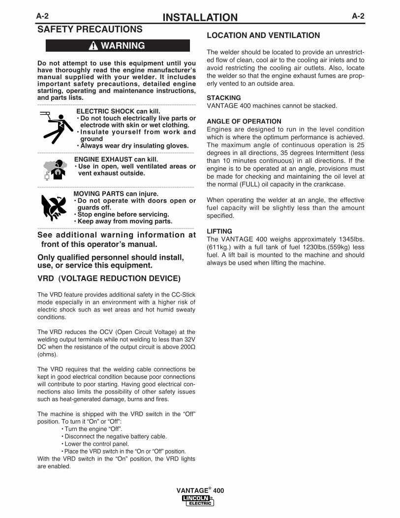
SAFETY PRECAUTIONS
Only qualified personnel should install, use, or service this equipment.
Do not attempt to use this equipment until youhave thoroughly read the engine manufacturerʼsmanual supplied with your welder. It includesimportant safety precautions, detailed enginestarting, operating and maintenance instructions,and parts lists.------------------------------------------------------------------------
ELECTRIC SHOCK can kill.• Do not touch electrically live parts or
electrode with skin or wet clothing.• Insulate yourself from work and
ground• Always wear dry insulating gloves.
------------------------------------------------------------------------ENGINE EXHAUST can kill.• Use in open, well ventilated areas or
vent exhaust outside.
------------------------------------------------------------------------MOVING PARTS can injure.• Do not operate with doors open or
guards off.• Stop engine before servicing.• Keep away from moving parts.
------------------------------------------------------------------------See additional warning information atfront of this operatorʼs manual.
WARNING
VRD (VOLTAGE REDUCTION DEVICE)
The VRD feature provides additional safety in the CC-Stickmode especially in an environment with a higher risk ofelectric shock such as wet areas and hot humid sweatyconditions.
The VRD reduces the OCV (Open Circuit Voltage) at thewelding output terminals while not welding to less than 32VDC when the resistance of the output circuit is above 200Ω(ohms).
The VRD requires that the welding cable connections bekept in good electrical condition because poor connectionswill contribute to poor starting. Having good electrical con-nections also limits the possibility of other safety issuessuch as heat-generated damage, burns and fires.
The machine is shipped with the VRD switch in the “Off”position. To turn it “On” or “Off”:
• Turn the engine “Off”.• Disconnect the negative battery cable.• Lower the control panel.• Place the VRD switch in the “On or “Off” position.
With the VRD switch in the “On” position, the VRD lightsare enabled.
LOCATION AND VENTILATION
The welder should be located to provide an unrestrict-ed flow of clean, cool air to the cooling air inlets and toavoid restricting the cooling air outlets. Also, locatethe welder so that the engine exhaust fumes are prop-erly vented to an outside area.
STACKINGVANTAGE 400 machines cannot be stacked.
ANGLE OF OPERATIONEngines are designed to run in the level conditionwhich is where the optimum performance is achieved.The maximum angle of continuous operation is 25degrees in all directions, 35 degrees Intermittent (lessthan 10 minutes continuous) in all directions. If theengine is to be operated at an angle, provisions mustbe made for checking and maintaining the oil level atthe normal (FULL) oil capacity in the crankcase.
When operating the welder at an angle, the effectivefuel capacity will be slightly less than the amountspecified.
LIFTINGThe VANTAGE 400 weighs approximately 1345lbs.(611kg.) with a full tank of fuel 1230lbs.(559kg) lessfuel. A lift bail is mounted to the machine and shouldalways be used when lifting the machine.

A-3INSTALLATION
VANTAGE® 400
A-3
HIGH ALTITUDE OPERATIONAt higher altitudes, output derating may be necessary. For max-imum rating, derate the machine 2.5% to 3.5% for every 1000 ft.(305m). Due to new EPA and other local emissions regulations,modifications to the engine for high altitude are restricted withinthe United States. For use above 6000 ft.(1828 m) an autho-rized Perkins engine field service shop should be contacted todetermine if any adjustments can be made for operation in high-er elevations.
HIGH TEMPERATURE OPERATIONAt temperatures above 104°F(40°C), Welder output derating isnecessary. For maximum output ratings, derate the welder out-put 2 volts for every 18°F(10°C) above 104°F(40°C).
Cold weather starting:
With a fully charged battery and the proper oil, the engineshould start satisfactorily down to -15°F(-26C°). If the enginemust be frequently started at or below 0°F (-18°C), it may bedesirable to install cold-starting aides. The use of No. 1Ddiesel fuel is recommended in place of No. 2D at tempera-tures below 23°F (-5°C). Allow the engine to warm up beforeapplying a load or switching to high idle.
Note: Extreme cold weather starting may requirelonger glow plug operation.
Under no conditions should ether or other startingfluids be used with this engine!------------------------------------------------------------------------TOWING
Use a recommended trailer for use with this equipment for road,in-plant and yard towing by a vehicle(1). If the user adapts anon-Lincoln trailer, he must assume responsibility that themethod of attachment and usage does not result in a safetyhazard or damage the welding equipment. Some of the factorsto be considered are as follows:
1. Design capacity of trailer vs. weight of Lincoln equipment andlikely additional attachments.
2. Proper support of, and attachment to, the base of the weldingequipment so there will be no undue stress to the framework.
3. Proper placement of the equipment on the trailer to insurestability side to side and front to back when being moved andwhen standing by itself while being operated or serviced.
4. Typical conditions of use, i.e., travel speed; roughness of sur-face on which the trailer will be operated; environmental con-ditions; like maintenance.
5. Conformance with federal, state and local laws.(1)
(1) Consult applicable federal, state and local laws regarding specific requirements for use on public high-
ways.
WARNING
• Lift only with equipment of ade-quate lifting capacity.
• Be sure machine is stable when lift-ing.
• Do not lift this machine using liftbail if it is equipped with a heavyaccessory such as trailer or gascylinder.
FALLING • Do not lift machine if lift bail is
EQUIPMENT can damaged.
cause injury. • Do not operate machine while
suspended from lift bail.
--------------------------------------------------------------------------------VEHICLE MOUNTING
Improperly mounted concentrated loads maycause unstable vehicle handling and tires or othercomponents to fail.
• Only transport this Equipment on serviceablevehicles which are rated and designed for suchloads.
• Distribute, balance and secure loads so vehicleis stable under conditions of use.
• Do not exceed maximum rated loads for compo-nents such as suspension, axles and tires.
• Mount equipment base to metal bed or frame ofvehicle.
• Follow vehicle manufacturerʼs instructions.------------------------------------------------------------------------
WARNING
PRE-OPERATION ENGINE SERVICEREAD the engine operating and maintenance instruc-tions supplied with this machine.
• Stop engine and allow to cool before fueling• Do not smoke when fueling.• Fill fuel tank at a moderate rate and do not over-
fill.• Wipe up spilled fuel and allow fumes to clear
before starting engine.• Keep sparks and flame away from tank.------------------------------------------------------------------------
WARNING
WARNING
OIL The VANTAGE 400 is shipped with the enginecrankcase filled with high quality SAE 10W-30 Oil thatmeets classification CG-4 or CH-4 for diesel engines.Check the oil level before starting the engine. If it isnot up to the full mark on the dip stick, add oil asrequired. Check the oil level every four hours of run-ning time during the first 50 running hours. Refer tothe engine Operatorʼs Manual for specific oil recom-mendations and break-in information. The oil changeinterval is dependent on the quality of the oil and theoperating environment. Refer to the Engine OperatorʼsManual for more details on the proper service andmaintenance intervals.
FUELDIESEL FUEL ONLY-Low sulphur fuel or ultralow sulphur fuel in U.S.A. and Canada.
• Fill the fuel tank with clean, fresh fuel. Thecapacity of the tank is 15 gals. (57 ltrs). Whenthe fuel gauge reads empty the tank containsapproximately 2 gals. (7.6ltrs.) of reserve fuel.
NOTE: A fuel shut off valve is located on the pre-filter/sediment filter. Which should be inthe closed position when the welder is notused for extended periods of time.
------------------------------------------------------------------------
ENGINE COOLING SYSTEMAir to cool the engine is drawn in the side andexhausted through radiator & case back. It isimportant that the intake and exhaust air is notrestricted. Allow a minimum clearance of 1ft.(0.6m) from the case back and 16in.(406mm) fromeither side of the base to a vertical surface.------------------------------------------------------------------------
BATTERY CONNECTIONUse caution as the electrolyte is a strong acid thatcan burn skin and damage eyes.------------------------------------------------------------------------The VANTAGE 400 is shipped with the negative bat-tery cable disconnected. Make certain that the RUN-STOP switch is in the STOP position. Remove the twoscrews from the battery tray using a screwdriver or a3/8" socket. Attach the negative battery cable to thenegative battery terminal and tighten using a 1/2"socket or wrench.
A-4INSTALLATION
VANTAGE® 400
A-4
NOTE: This machine is furnished with a wet chargedbattery; if unused for several months, the battery mayrequire a booster charge. Be careful to charge the bat-tery with the correct polarity. (See Battery in“Maintenance Section”)
MUFFLER OUTLET PIPEUsing the clamp provided secure the outlet pipe to theoutlet tube with the pipe positioned such that it willdirect the exhaust in the desired direction. Tightenusing a 9/16" socket or wrench.
SPARK ARRESTERSome federal, state or local laws may require thatgasoline or diesel engines be equipped with exhaustspark arresters when they are operated in certainlocations where unarrested sparks may present a firehazard. The standard muffler included with this welderdoes not qualify as a spark arrester. When required bylocal regulations, a suitable spark arrester, such asthe K903-1 must be installed and properly maintained.
An incorrect spark arrestor may lead to damage tothe engine or adversely affect performance.------------------------------------------------------------------------REMOTE CONTROLThe VANTAGE 400 is equipped with a 6-pin and a 14-pin connector. The 6-pin connector is for connectingthe K857 or K857-1 Remote Control or for TIG weld-ing, the K870 foot Amptrol or the K963-3 handAmptrol. When in the CC-STICK, DOWNHILL PIPE,or CV-WIRE modes and when a remote control isconnected to the 6-pin Connector, the auto-sensingcircuit automatically switches the OUTPUT controlfrom control at the welder to remote control.
When in TOUCH START TIG mode and when aAmptrol is connected to the 6-Pin Connector, theOUTPUT dial is used to set the maximum currentrange of the CURRENT CONTROL of the Amptrol.
The 14-pin connector is used to directly connect awire feeder control cable. In the CV-WIRE mode,when the control cable is connected to the 14-pin con-nector, the auto-sensing circuit automatically makesthe Output Control inactive and the wire feeder volt-age control active
NOTE: When a wire feeder with a built in weldingvoltage control is connected to the 14-pin connec-tor, do not connect anything to the 6-pin connec-tor.
------------------------------------------------------------------------
WARNING
WARNING
CAUTION
WARNING
WARNING
WARNING
A-5INSTALLATION
VANTAGE® 400
A-5
ELECTRICAL CONNECTIONS
MACHINE GROUNDINGBecause this portable engine driven welder creates itsown power, it is not necessary to connect its frame toan earth ground, unless the machine is connected topremises wiring (home, shop, etc.)
To prevent dangerous electric shock, other equipmentto which this engine driven welder supplies powermust:
• Be grounded to the frame of the welder using agrounded type plug or be double insulated.
• Do not ground the machine to a pipe that carriesexplosive or combustible material.
------------------------------------------------------------------------
When this welder is mounted on a truck or trailer, itsframe must be electrically bonded to the metal frameof the vehicle. Use a #8 or larger copper wire connect-ed between the machine grounding stud and theframe of the vehicle. When this engine driven welderis connected to premises wiring such as that in ahome or shop, its frame must be connected to thesystem earth ground. See further connection instruc-tions in the section entit led "Standby PowerConnections" as well as the article on grounding in thelatest National Electrical Code and the local code.
In general, if the machine is to be grounded, it shouldbe connected with a #8 or larger copper wire to a solidearth ground such as a metal water pipe going intothe ground for at least ten feet and having no insulat-ed joints, or to the metal framework of a buildingwhich has been effectively grounded.
The National Electrical Code lists a number of alter-nate means of grounding electrical equipment. Amachine grounding stud marked with the symbolis provided on the front of the welder.
WELDING TERMINALSThe VANTAGE 400 is equipped with a toggle switchfor selecting "hot" welding terminal when in the"WELD TERMINALS ON" position or "cold" weldingterminal when in the "REMOTELY CONTROLLED"position.
WARNING
WELDING OUTPUT CABLES With the engine off connect the electrode and workcables to the output studs. The welding process dic-tates the polarity of the electrode cable. These con-nections should be checked periodically and tightenedwith a 3/4" wrench.
Table A.1 lists recommended cable sizes and lengthsfor rated current and duty cycle. Length refers to thedistance from the welder to the work and back to thewelder. Cable diameters are increased for long cablelengths to reduce voltage drops.
TABLE A.1
CABLE INSTALLATIONInstall the welding cables to your VANTAGE 400 asfollows.
1. The engine must be OFF to install welding cables.
2. Remove the flanged nuts from the output terminals.3. Connect the electrode holder and work cables to
the weld output terminals. The terminals are identi-fied on the case front.
4. Tighten the flanged nuts securely.
5. Be certain that the metal piece you are welding (the“work”) is properly connected to the work clamp andcable.
6. Check and tighten the connections periodically.
• Loose connections will cause the output termi-nals to overheat. The terminals may eventuallymelt.
• Do not cross the welding cables at the output ter-minal connection. Keep the cables isolated andseparate from one another.
------------------------------------------------------------------------
TOTAL COMBINED LENGTH OFELECTRODE AND WORK CABLES
Cable Length
0-100 Ft. (0-30 meters)
100-150 Ft. (30-46 meters)
150-200 Ft. (46-61 meters)
Cable Size for 400 Amps
60% Duty Cycle2 / 0 AWG
2 / 0 AWG
3 / 0 AWG
CAUTION

All auxiliary power is protected by circuit breakers.The 120V has 20 Amp circuit breakers for eachduplex receptacle. The 120/240V Single Phase andthe 240V Three-Phases have a 50 Amp 3-pole CircuitBreaker that disconnects both hot leads and all ThreePhases simultaneously.
STANDBY POWER CONNECTIONS
The VANTAGE 400 is suitable for temporary, standbyor emergency power using the engine manufacturerʼsrecommended maintenance schedule.
The VANTAGE 400 can be permanently installed asa standby power unit for 240 VAC, 3 wire, singlephase, 50 amp service. Connections must be madeby a licensed electrician who can determine how the120/240 VAC power can be adapted to the particularinstallation and comply with all applicable electricalcodes.
• Install the double-pole, double-throw switchbetween the power company meter and the premis-es disconnect. Switch rating must be the same orgreater than the customerʼs premises disconnectand service over current protection.
• Take necessary steps to assure load is limited tothe capacity of the generator by installing a 50amp, 240 VAC double pole circuit breaker.Maximum rated load for each leg of the 240 VACauxiliary is 50 amperes. Loading above the ratedoutput will reduce output voltage below the allow-able - 10% of rated voltage which may damageappliances or other motor-driven equipment andmay result in overheating of the engine and/oralternator windings.
• Install a 50 amp, 120/240 VAC plug (NEMA Type14-50P) to the double-pole circuit breaker usingNo. 6, 4 conductor cable of the desired length. (The50 amp, 120/240 VAC plug is available in theoptional K802R plug kit or as part number T12153-9.)
• Plug this cable into the 50 Amp, 120/240 Voltreceptacle on the case front.
AUXILIARY POWER RECEPTACLES
Start the engine and set the “IDLER” control switch tothe “High Idle” mode. Voltage is now correct at thereceptacles for auxiliary power. This must be donebefore a tripped GFCI receptacle can be reset proper-ly. See the MAINTENANCE section for more detailedinformation on testing and resetting the GFCI recepta-cle.
The auxiliary power of the VANTAGE 400 consists oftwo 20 Amp-120 VAC (5-20R) duplex receptacles withGFCI protection, one 50 Amp 120/240 VAC (14-50R)receptacle and one 50 Amp 240VAC Three-Phase (15-50R) receptacle.
The auxiliary power capacity is 12,000 watts Peak,11,000 Watts Continuous of 60 Hz, single phasepower. The auxiliary power capacity rating in watts isequivalent to volt-amperes at unity power factor. Themax permissible current of the 240 VAC output is50amps.
The 240 VAC output can be split to provide two sepa-rate 120 VAC outputs with a max permissible currentof 50 Amps per output to two separate 120 VACbranch circuits (these circuits cannot be paralleled).Output voltage is within ± 10% at all loads up to ratedcapacity.
The Three-Phases auxiliary power capacity is 19,000watts peak, 17,000 watts continuous. The maximumcurrent is 45 amps.
120 V GFCI DUPLEX RECEPTACLES
A GFCI (Ground Fault Circuit Interrupter) electricalreceptacle is a device to protect against electric shockshould a piece of defective equipment connected to itdevelop a ground fault. If this situation should occur,the GFCI will trip, removing voltage from the output ofthe receptacle. If a GFCI receptacle is tripped see theMAINTENANCE section for detailed information ontesting and resetting it. A GFCI receptacle should beproperly tested at least once every month.
The 120 V auxiliary power receptacles should only beused with three wire grounded type plugs or approveddouble insulated tools with two wire plugs. The currentrating of any plug used with the system must be atleast equal to the current capacity of the associatedreceptacle.
NOTE: The 240 V receptacle has two 120 V circuits,but are of opposite polarities and cannot be paralleled.
A-6INSTALLATION
VANTAGE® 400
A-6
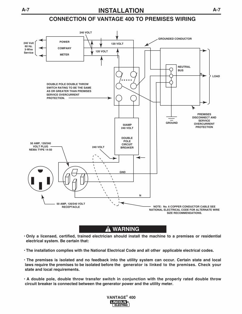
CONNECTION OF VANTAGE 400 TO PREMISES WIRING
WARNING• Only a licensed, certified, trained electrician should install the machine to a premises or residential
electrical system. Be certain that:
• The installation complies with the National Electrical Code and all other applicable electrical codes.
• The premises is isolated and no feedback into the utility system can occur. Certain state and locallaws require the premises to be isolated before the generator is linked to the premises. Check yourstate and local requirements.
• A double pole, double throw transfer switch in conjunction with the properly rated double throwcircuit breaker is connected between the generator power and the utility meter.
A-7INSTALLATION
VANTAGE® 400
A-7

CONNECTION OF LINCOLN ELECTRICWIRE FEEDERS
Connection of LN-7 or LN-8 to the VANTAGE 400
1. Shut the welder off.
2. Connect the LN-7 or LN-8 per instructions on theappropriate connection diagram in Section F.
3. Set the "WIRE FEEDER VOLTMETER" switch toeither "+" or "-" as required by the electrode beingused.
4. Set the "MODE" switch to the "CV WIRE " posi-tion.
5. Set the "ARC CONTROL" knob to "0" initially andadjust to suit.
6. Set the "WELD TERMINALS" switch to the"REMOTELY CONTROLLED" position.
7. Set the "IDLE" switch to the "HIGH" position.
Connection of LN-15 to the VANTAGE 400
1. Shut the welder off.
2. For electrode Positive, connect the electrodecable to the "+" terminal of the welder and workcable to the "-" terminal of the welder. For elec-trode Negative, connect the electrode cable to the"-" terminal of the welder and work cable to the "+"terminal of the welder.
3. Across The-Arc Model:
• Attach the single lead from the front of the LN-15to work using the spring clip at the end of thelead. This is a control lead to supply current tothe wire feeder motor; it does not carry weldingcurrent.
• Set the "WELD TERMINALS" switch to "WELDTERMINALS ON".
• When the gun trigger is closed, the current sens-ing circuit will cause the VANTAGE 400 engineto go to the high idle speed, the wire will begin tofeed and the welding process started. Whenwelding is stopped, the engine will revert to lowidle speed after approximately 12 secondsunless welding is resumed.
4. Control Cable Model:
• Connect Control Cable between Engine Welderand Feeder.
• Set the "WELD TERMINALS" switch to"REMOTELY CONTROLLED"
• Set the MODE switch to the "CV-WIRE " position.
• Set the "WIRE FEEDER VOLTMETER" switch toeither "+" or "-" as required by the electrode polar-ity being used.
• Set the "ARC CONTROL" knob to "0" initially andadjust to suit.
• Set the "IDLE" switch to the "AUTO" position.
• When the gun trigger is closed, the current sens-ing circuit will cause the VANTAGE 400 engine togo to the high idle speed, the wire will begin tofeed and the welding process started. Whenwelding is stopped, the engine will revert to lowidle speed after approximately 12 seconds unlesswelding is resumed.
A-8INSTALLATION
VANTAGE® 400
A-8

A-9INSTALLATION
VANTAGE® 400
A-9
Spool Gun (K487-25) and Cobramatic to VANTAGE400
• Shut the welder off.
• Connect per instructions on the appropriate connec-tion diagram in Section F.
Connection of PRINCE XL SPOOL GUN to theVANTAGE 400
Connection of the Prince XL Spool Gun requires theuse of the K1849-1 Adapter Module.
• Shut the Welder off.
• For electrode Positive, connect the electrode cableto the "+" terminal of the welder and work cable tothe "-" terminal of the welder. For electrodeNegative, connect the electrode cable "-" terminal ofthe welder and work cable to the "+" terminal of thewelder.
• Connect the Control Cable of the Spool Gun to theAdapter Module and connect the Control Cable ofthe Adapter Module to the Welder.
• Connect the Gas Hose.
• Set the MODE switch to the "CV-WIRE " position.
• Set the "WELD TERMINALS" switch to "WELDTERMINALS ON".
• Set the "ARC CONTROL" knob to "0" initially andadjust to suit.
• Set the “IDLE” switch to the “HIGH” position.
Connection of the LN-25 to the VANTAGE 400Shut off welder before making any electrical con-nections.------------------------------------------------------------------------The LN-25 with or without an internal contactor maybe used with the VANTAGE 400. See the appropriateconnection diagram in Section F.
1. Shut the welder off.
2. For electrode Positive, connect the electrodecable from the LN-25 to the "+" terminal of thewelder and work cable to the "-" terminal of thewelder. For electrode Negative, connect the elec-trode cable from the LN-25 to the "-" terminal ofthe welder and work cable to the "+" terminal ofthe welder.
3. Attach the single lead from the front of the LN-25to work using the spring clip at the end of the lead.This is a control lead to supply current to the wirefeeder motor; it does not carry welding current.
4. Set the MODE switch to the "CV-WIRE " position.
5. Set the "WELD TERMINALS" switch to "WELDTERMINALS ON"
6. Set the "ARC CONTROL" knob to "0" initially andadjust to suit.
7. Set the "IDLE" switch to the "AUTO" position.When not welding, the VANTAGE 400 engine willbe at the low idle speed. If you are using an LN-25with an internal contactor, the electrode is notenergized until the gun trigger is closed.
8. When the gun trigger is closed, the current sens-ing circuit will cause the VANTAGE 400 engine togo to the high idle speed, the wire will begin tofeed and the welding process started. When weld-ing is stopped, the engine will revert to low idlespeed after approximately 12 seconds unlesswelding is resumed.
If you are using an LN-25 without an internal con-tactor, the electrode will be energized when theVANTAGE 400 is started.------------------------------------------------------------------------
WARNING
CAUTION
B-1OPERATION
VANTAGE® 400
B-1
SAFETY PRECAUTIONS
Do not attempt to use this equipment until youhave thoroughly read the engine manufacturerʼsmanual supplied with your welder. It includesimportant safety precautions, detailed enginestarting, operating and maintenance instructions,and parts lists.------------------------------------------------------------------------
ELECTRIC SHOCK can kill.• Do not touch electrically live parts or
electrode with skin or wet clothing.• Insulate yourself from work and
ground• Always wear dry insulating gloves.
• Always operate the welder with the hinged doorclosed and the side panels in place.
• Read carefully the Safety Precautions pagebefore operating this machine. Always followthese and any other safety procedures includedin this manual and in the Engine InstructionManual.
GENERAL DESCRIPTIONThe VANTAGE 400 is a diesel engine powered DCmulti-process welding power source and 120 / 240volt AC power generator. The engine drives a genera-tor that supplies three phase power for the DC weld-ing circuit, single phase and Three Phase power forthe AC auxiliary outlets. The DC welding control sys-
tem uses state of the art Chopper Technology (CT™)for superior welding performance.
The Vantage 400 is f i t ted with a selectableVRD(Voltage Reduction Device). The VRD operatesin the CC-Stick mode reducing the OCV to <13 volts,increasing operator safety when welding is performedin environments with increased hazard of electricshock.
FOR AUXILIARY POWER:Start the engine and set the IDLER control switch tothe desired operating mode. Full power is availableregardless of the welding control settings providing nowelding current is being drawn.
ENGINE OPERATIONBefore Starting the Engine:
• Be sure the machine is on a level surface.• Open side engine door and remove the engine oil
dipstick and wipe it with a clean cloth. Reinsert thedipstick and check the level on the dipstick.
• Add oil (if necessary) to bring the level up to the fullmark. Do not overfill. Close engine door.
• Check radiator for proper coolant level. (Fill if nec-essary).
• See Engine Ownerʼs Manual for specific oil andcoolant recommendations.
ADD FUEL• Stop engine while fueling.• Do not smoke when fueling.• Keep sparks and flame away
from tank.• Do not leave unattended
while fueling.• Wipe up spilled fuel and allow
fumes to clear before startingengine.
• Do not overfil l tank, fuelexpansion may cause over-flow.
DIESEL FUEL ONLY- Low sulphur fuel or ultra lowsulphur fuel in U.S.A. and Canada.------------------------------------------------------------------------• Remove the fuel tank cap.
• Fill the tank. DO NOT FILL THE TANK TO THEPOINT OF OVERFLOW.
• Replace the fuel cap and tighten securely.
• See Engine Ownerʼs Manual for specific fuel recom-mendations.
BREAK-IN PERIOD
The engine will use a small amount of oil during its“break-in” period. The break-in period is about 50 run-ning hours.
Check the oil every four hours during break-in.Change the oil after the first 50 hours of operation andevery 200 hours thereafter. Change the oil filter ateach oil change.
During break-in, subject the Welder to moderateloads. Avoid long periods running at idle. Beforestopping the engine, remove all loads and allowthe engine to cool several minutes.------------------------------------------------------------------------
WARNING
WARNING
CAUTION
DIESEL FUELcan cause fire.

B-2OPERATIONB-2
WELDING CONTROLS (Figure B.1)
1. OUTPUT CONTROL- The OUTPUT dial isused to preset the output voltage or current as dis-played on the digital meters for the four weldingmodes. When in the CC-STICK, DOWNHILL PIPEor CV-WIRE modes and when a remote control isconnected to the 6-Pin or 14-Pin Connector, theauto-sensing circuit automatically switches theOUTPUT CONTROL from control at the welder tothe remote control.
In the CV-WIRE mode, if the feeder being used hasa voltage control when the wire feeder control cableis connected to the 14-Pin Connector, the auto-sensing circuit automatically makes OUTPUT CON-TROL inactive and the wire feeder voltage controlactive. Otherwise, the OUTPUT CONTROL is usedto preset the voltage
When in the TOUCH START TIG mode and whenan Amptrol is connected to the 6-Pin Connector, theOUTPUT dial is used to set the maximum currentrange of the CURRENT CONTROL of the Amptrol.
2. DIGITAL OUTPUT METERS-The digitalmeters allow the output voltage (CV-WIRE mode)or current (CC-STICK,DOWN HILL PIPE and TIGmodes) to be set prior to welding using the OUT-PUT control dial. During welding, the meter displaythe actual output voltage (VOLTS) and current(AMPS). A memory feature holds the display ofboth meters on for seven seconds after welding isstopped. This allows the operator to read the actualcurrent and voltage just prior to when welding wasceased.
While the display is being held the left-most deci-mal point in each display will be flashing. Theaccuracy of the meters is +/- 3%.
3. WELD MODE SELECTOR SWITCH-(Provides four selectable welding modes)
CV-WIREDOWNHILL PIPECC-STICKTOUCH START TIG
1
9
11
20
7
410
5
8
12
13
15
19
6
21
14
18
17
16
2
3
FIGURE B.1
VANTAGE® 400
B-3OPERATIONB-3
4. ARC CONTROL- The ARC CONTROL dial is active inthe CV-WIRE, CC-STICK and DOWNHILL PIPE modes,and has different functions in these modes. This control isnot active in the TIG mode.
CC-STICK mode: In this mode, the ARC CONTROL dialsets the short circuit current (arc-force) during stick weldingto adjust for a soft or crisp arc. Increasing the dial from –10(soft) to +10 (crisp) increases the short circuit current andprevents sticking of the electrode to the plate while welding.This can also increase spatter. It is recommended that theARC CONTROL be set to the minimum number withoutelectrode sticking. Start with a setting at 0.
DOWNHILL PIPE mode: In this mode, the ARC CONTROLdial sets the short circuit current (arc-force) during stickwelding to adjust for a soft or a more forceful digging arc(crisp). Increasing the number from –10 (soft) to +10 (crisp)increases the short circuit current which results in a moreforceful digging arc. Typically a forceful digging arc is pre-ferred for root and hot passes. A softer arc is preferred for filland cap passes where weld puddle control and deposition("stacking" of iron) are key to fast travel speeds. It is recom-mended that the ARC CONTROL be set initially at 0.
CV-WIRE mode: In this mode, turning the ARC CONTROLclock wise from –10 (soft) to +10 (crisp) changes the arcfrom soft and washed-in to crisp and narrow. It acts as aninductance/pinch control. The proper setting depends on theprocedure and operator preference. Start with a setting of 0.
5. WELD OUTPUT TERMINALS WITH FLANGENUT- Provides a connection point for the electrode andwork cables.
6. GROUND STUD- Provides a connection point forconnecting the machine case to earth ground.
7. 14-PIN CONNECTOR- For attaching wire feeder con-trol cables. Includes contactor closure circuit, auto-sensingremote control circuit, and 120V and 42V power. Theremote control circuit operates the same as the 6 PinAmphenol.
8. 6-PIN CONNECTOR- For attaching optional remotecontrol equipment. Includes auto-sensing remote controlcircuit.
9. WELD TERMINALS CONTROL SWITCH- In theWELD TERMINALS ON position, the output is electricallyhot all the time. In the REMOTELY CONTROLLED posi-tion, the output is controlled by a wire feeder or amptroldevice, and is electrically off until a remote switch isdepressed.
10. WIRE FEEDER VOLTMETER SWITCH:Matches the polarity of the wire feeder voltmeter tothe polarity of the electrode.
11. VRD (Voltage Reduction Device) INDICA-TOR LIGHTS- On the front panel of the Vantage400 are two indicator lights. A red light when lit indi-cates OCV(Open Circuit Voltage) is equal to orgreater than 32V and a green light when lit indicatesOCV(Open Circuit Voltage) is less than 32V.
The VRD “On/Off” switch inside the control panelmust be “On” for the VRD function to be active andthe lights to be enabled. When the machine is firststarted with VRD enabled, both lights will illuminatefor 5 seconds.
These lights monitor the OCV(Open Circuit Voltage)and weld voltage at all times. In the CC-Stick modewhen not welding the green light will illuminate indi-cating that the VRD has reduced the OCV to lessthan 32V. During welding the red light will illuminatewhenever the arc voltage is equal to or greater than32V. This means that the red and green light mayalternate depending on the weld voltage. This is nor-mal operation.
If the red light remains illuminated when not weldingin the CC-stick mode, the VRD is not functioningproperly. Please refer to your local field service shopfor service.
If the VRD is turned “On” and the lights donʼt come“On”, refer to the trouble shooting section.
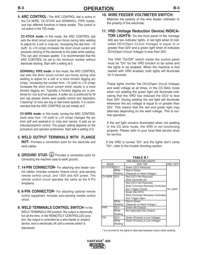
TABLE B.1VRD INDICATOR LIGHTS
MODE VRD "ON" VRD "OFF" CC-STICK OCV Green (OCV Reduced)
While Red or GreenWelding (Depends on Weld Voltage) *
CV-WIRE OCV Red (OCV Not Reduced)Weld Terminals OnRed (OCV Not Reduced)Weld Terminals Remotely ControlledGun Trigger Closed No LightsGreen (No OCV)Weld Terminals Remotely ControlledGun Trigger Open
While Red or GreenWelding (Depends on Weld Voltage) *
PIPE OCV Green (No Output)While Not Applicable (No Output)Welding
TIG OCV Green (Process is Low Voltage)While Green (Process is Low Voltage)Welding
* It is normal for the lights to alternate between colors while welding.
VANTAGE® 400

TYPICAL VANTAGE 400 FUEL CONSUMPTIONTABLE B.2
PERKINS 404C-22 & 404D-22Gal./Hr (Liters/Hr)
.26 (.97)
.42 (1.57)
1.18 (4.46)1.24 (4.68).90 (3.42)
Running Time for15 gallons / hours
58.59
36.06
12.7412.1416.62
Low Idle - No Load1400 R.P.M.High Idle - No Load1880 R.P.M.DC Weld Output400 Amps @ 36 Volts 17,000 Watts 3 Phase11,000 Watts 1 Phase
NOTE: This data is for reference only. Fuel consump-tion is approximate and can be influenced by manyfactors, including engine maintenance, environmentalconditions and fuel quality.
B-4OPERATIONB-4
ENGINE CONTROLS: 12. RUN/STOP SWITCH - RUN position energizes the
engine prior to starting. STOP position stops theengine. The oil pressure interlock switch prevents bat-tery drain if the switch is left in the RUN position andthe engine is not operating.
13. GLOW PLUG PUSH BUTTON -• When pushed activates the glow plugs. Glow plug
should not be activated for more than 20 seconds con-tinuously.
14. START PUSH BUTTON - Energizes the startermotor to crank the engine.
15. IDLER SWITCH- Has two positions as follows:1) In the HIGH position, the engine runs at the high idle
speed controlled by the engine governor.2) In the AUTO position, the idler operates as follows:• When switched from HIGH to AUTO or after starting
the engine, the engine will operate at full speed forapproximately 12 seconds and then go to low idlespeed.
• When the electrode touches the work or power isdrawn for lights or tools (approximately 100 Watts mini-mum), the engine accelerates and operates at fullspeed.
• When welding ceases or the AC power load is turnedoff, a fixed time delay of approximately 12 secondsstarts. If the welding or AC power load is not restartedbefore the end of the time delay, the idler reduces theengine speed to low idle speed.
• The engine will automatically return to high idle speedwhen there is welding load or AC power load reapplied.
16. ELECTRIC FUEL GAUGE- The electric fuelgauge gives accurate and reliable indication as to howmuch fuel is in the fuel tank.
17. ENGINE HOUR METER- Displays the total timethat the engine has been running. This meter is usefulfor scheduling prescribed maintenance.
18. ENGINE PROTECTION LIGHT- A warning indi-cator light for Low Oil Pressure and/or Coolant OverTemperature.The light is off when the systems are func-tioning properly. The light will come on and the enginewill shutdown when there is Low Oil Pressure and/orthe Coolant is Over Temperature.
Note: The light remains off when the RUN-STOP switchis in the "ON" posit ion prior to starting theengine.However if the engine is not started within 60seconds the light will come on. When this happens theRUN-STOP switch must be returned to the "OFF" posi-tion to reset the engine protection system and light.
19. BATTERY CHARGING LIGHT- A warning indica-tor light for Low/No battery charge. The light is off whenthe systems are functioning properly. The light willcome on if there is a Low/No battery condition but themachine will continue to run.
Note: The light may or may not come on when the RUN-STOP switch is in the "ON" position. It will come on duringcranking and stay on until the engine starts. After startingthe engine the light will go off unless a Low/No batterycharge condition exists.
20. COOLANT TEMPERATURE GAUGE-A indica-tor of engine coolant temperature.
21. OIL PRESSURE GAUGE- A indicator of engineOil Pressure.
STARTING THE ENGINE1. Remove all plugs connected to the AC power recepta-
cles.2. Set IDLER switch to AUTO.
3. Press Glow Plug Button and hold 15 to 20 seconds.4. Set the RUN/STOP switch to RUN.5. Press START button until the engine starts or for up to
10 seconds. Continue to hold the glow plug button for upto an additional 10 seconds.
6. Release the engine START button immediately whenthe engine starts.
7. The engine will run at high idle speed for approximately12 seconds and then drop to low idle speed. Allow theengine to warm up at low idle for several minutes beforeapplying a load and/or switching to high idle. Allow alonger warm up time in cold weather.
VANTAGE® 400

WELDER OPERATIONDUTY CYCLE
Duty Cycle is the percentage of time the load is beingapplied in a 10 minute period. For example a 60% dutycycle, represents 6 minutes of load and 4 minutes of noload in a 10 minute period.
ELECTRODE INFORMATION
For any electrode the procedures should be kept with-in the rating of the machine. For information on elec-trodes and their proper application see(www.lincolnelectric.com) or the appropriate Lincolnpublication.
The VANTAGE 400 can be used with a broad range ofDC stick electrodes. The MODE switch provides twostick welding settings as follows:
CONSTANT CURRENT (CC-STICK) WELDING
The CC-STICK position of the MODE switch is designedfor horizontal and vertical-up welding with all types ofelectrodes, especially low hydrogen. The OUTPUT CON-
B-5OPERATIONB-5
VANTAGE® 400
NOTE: If the unit fails to start turn Run/Stop switchto off and repeat step 3 through step 7 afterwaiting 30 seconds.
• Do not allow the starter motor to run continuouslyfor more than 20 seconds.
• Do not push the START button while the engineis running because this can damage the ringgear and/or the starter motor.
• IF the Engine Protection or Battery ChargingLights do “not” turn off shortly after starting theengine shut off the engine immediately anddetermine the cause.
-----------------------------------------------------------------------NOTE: When starting for the first time, or after andextended period of time of not operating, it will takelonger than normal to start because the fuel pump hasto fill the fuel system. For best results, bleed the fuelsystem as indicated in Maintenance Section of thismanual.
STOPPING THE ENGINERemove all welding and auxiliary power loads andallow the engine to run at low idle speed for a fewminutes to cool the engine.
STOP the engine by placing the RUN-STOP switch inthe STOP position.
NOTE: A fuel shut off valve is located on the fuel pre-filter.
CAUTION
TROL dial adjusts the full output range for stick weld-ing.The ARC CONTROL dial sets the short circuit current(arc-force) during stick welding to adjust for a soft orcrisp arc. Increasing the number from -10(soft) to+10(crisp) increases the short circuit current and pre-vents sticking of the electrode to the plate while welding.This can also increase spatter. It is recommended thatthe ARC CONTROL be set to the minimum numberwithout electrode sticking. Start with the dial set at 0.
NOTE: Due to the low OCV with the VRD on, avery slight delay during striking of the electrodesmay occur. Due to the requirement of the resis-tance in the circuit to be low for a VRD to operate, agood metal-to-metal contact must be madebetween the metal core of the electrode and thejob. A poor connection anywhere in the weldingoutput circuit may limit the operation of the VRD.This includes a good connection of the work clampto the job. The work clamp should be connected asclose as practical to where the welding will be per-formed.
A. For New ElectrodesE6010 - Touch, Lift to Start the ArcE7018, E7024 - Touch, Rock Back and Forth in
Joint, Lift .
Once the arc is started, normal welding techniquefor the application is then used.
B. For Re-Striking ElectrodesSome electrodes form a cone at the end of theelectrode after the welding arc has been broken,particularly iron powder and low hydrogen elec-trodes. This cone will need to be broken off in orderto have the metal core of the electrode make con-tact.
E6010 - Push, Twist in Joint, LiftE7018, E7024 - Push, Rock Back and Forth in
Joint, Lift.
Once the arc is started, normal welding techniquefor the application is then used.
For other electrodes the above techniques shouldbe tried first and varied as needed to suit operatorpreference. The goal for successful starting is goodmetal to metal contact.
For indicator light operation, see table B.1.
DOWNHILL PIPE Welding
This slope controlled setting is intended for "out-of-position" and "down hill" pipe welding where the oper-
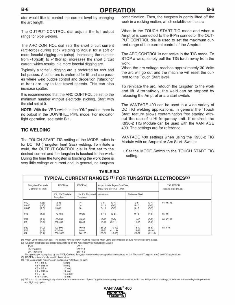
contamination. Then, the tungsten is gently lifted off thework in a rocking motion, which establishes the arc.
When in the TOUCH START TIG mode and when aAmptrol is connected to the 6-Pin connector the OUT-PUT CONTROL dial is used to set the maximum cur-rent range of the current control of the Amptrol.
The ARC CONTROL is not active in the TIG mode. ToSTOP a weld, simply pull the TIG torch away from thework. When the arc voltage reaches approximately 30 Voltsthe arc will go out and the machine will reset the cur-rent to the Touch Start level.
To reinitiate the arc, retouch the tungsten to the workand lift. Alternatively, the weld can be stopped byreleasing the Amptrol or arc start switch.
The VANTAGE 400 can be used in a wide variety ofDC TIG welding applications. In general the ʻTouchStartʼ feature allows contamination free starting with-out the use of a Hi-frequency unit. If desired, theK930-2 TIG Module can be used with the VANTAGE400. The settings are for reference.
VANTAGE 400 settings when using the K930-2 TIGModule with an Amptrol or Arc Start Switch:
• Set the MODE Switch to the TOUCH START TIGsetting.
ator would like to control the current level by changingthe arc length.
The OUTPUT CONTROL dial adjusts the full outputrange for pipe welding.
The ARC CONTROL dial sets the short circuit current(arc-force) during stick welding to adjust for a soft ormore forceful digging arc (crisp). Increasing the numberfrom -10(soft) to +10(crisp) increases the short circuitcurrent which results in a more forceful digging arc.
Typically a forceful digging arc is preferred for root andhot passes. A softer arc is preferred for fill and cap pass-es where weld puddle control and deposition (“stacking”of iron) are key to fast travel speeds. This can alsoincrease spatter.
It is recommended that the ARC CONTROL be set to theminimum number without electrode sticking. Start withthe dial set at 0.
NOTE: With the VRD switch in the “ON” position there isno output in the DOWNHILL PIPE mode. For indicatorlight operation, see table B.1.
TIG WELDING
The TOUCH START TIG setting of the MODE switch isfor DC TIG (Tungsten Inert Gas) welding. To initiate aweld, the OUTPUT CONTROL dial is first set to thedesired current and the tungsten is touched to the work.During the time the tungsten is touching the work there isvery little voltage or current and, in general, no tungsten
TYPICAL CURRENT RANGES (1) FOR TUNGSTEN ELECTRODES(2)
Tungsten Electrode DCEN (-) DCEP (+) Approximate Argon Gas Flow TIG TORCH
Diameter in. (mm) Flow Rate C.F.H. ( l /min.) Nozzle Size (4), (5)
1%, 2% Thoriated 1%, 2% Thoriated Aluminum Stainless SteelTungsten Tungsten
.010 (.25) 2-15 (3) 3-8 (2-4) 3-8 (2-4) #4, #5, #60.020 (.50) 5-20 (3) 5-10 (3-5) 5-10 (3-5)0.040 (1.0) 15-80 (3) 5-10 (3-5) 5-10 (3-5)
1/16 (1.6) 70-150 10-20 5-10 (3-5) 9-13 (4-6) #5, #6
3/32 (2.4) 150-250 15-30 13-17 (6-8) 11-15 (5-7) #6, #7, #81/8 (3.2) 250-400 25-40 15-23 (7-11) 11-15 (5-7)
5/32 (4.0) 400-500 40-55 21-25 (10-12) 13-17 (6-8) #8, #103/16 (4.8) 500-750 55-80 23-27 (11-13) 18-22 (8-10)1/4 (6.4) 750-1000 80-125 28-32 (13-15) 23-27 (11-13)
(1) When used with argon gas. The current ranges shown must be reduced when using argon/helium or pure helium shielding gases.(2) Tungsten electrodes are classified as follows by the American Welding Society (AWS):
Pure EWP1% Thoriated EWTh-12% Thoriated EWTh-2
Though not yet recognized by the AWS, Ceriated Tungsten is now widely accepted as a substitute for 2% Thoriated Tungsten in AC and DC applications.(3) DCEP is not commonly used in these sizes.(4) TIG torch nozzle "sizes" are in multiples of 1/16ths of an inch:
# 4 = 1/4 in. (6 mm)# 5 = 5/16 in. (8 mm)# 6 = 3/8 in. (10 mm)# 7 = 7/16 in. (11 mm)# 8 = _ in. (12.5 mm)#10 = 5/8 in. (16 mm)
(5) TIG torch nozzles are typically made from alumina ceramic. Special applications may require lava nozzles, which are less prone to breakage, but cannot withstand high temperaturesand high duty cycles.
B-6OPERATIONB-6
TABLE B.3
VANTAGE® 400

Carbon Diameter Current Range (DC, electrode positive)
1/8" 60-90 Amps
5/32" 90-150 Amps
3/16" 200-250 Amps
1/4" 300-400 Amps
5/16” 450-550 Amps
AUXILIARY POWER:Start the engine and set the IDLER control switch tothe desired operating mode. Full power is availableregardless of the welding control settings providing nowelding current is being drawn.
Simultaneous Welding and Auxiliary Power LoadsThe auxiliary power ratings are with no welding load.Simultaneous welding and power loads are specifiedin the following table.
WeldAmps
0100200300400500
1 PHASEWATTS AMPS11,000 4611,000 468,000 334700 201700 7
0 0
3 PHASEWATTS AMPS17,000 4115,400 3713,000 319400 233400 8
0 0
BOTH 1 & 3 PHASEWATTS AMPS11,000 -11,000 - 8,000 -4,700 -1,700 -
0 0
VANTAGE 400 Simultaneous Welding and Power Loads
PLUS OR OR
VANTAGE® 400
B-7OPERATIONB-7
ARC GOUGINGThe VANTAGE 400 can be used for arc gouging. For opti-mal performance, set the MODE switch to CC-STICK andthe ARC CONTROL to +10.
Set the OUTPUT CONTROL knob to adjust output currentto the desired level for the gouging electrode being usedaccording to the ratings in the following Table B.4.
• Set the "IDLER" Switch to the "AUTO" position.
• Set the "WELDING TERMINALS" switch to the"REMOTELY CONTROLLED" position. This will keep the"Solid State" contactor open and provide a "cold" elec-trode until the Amptrol or Arc Start Switch is pressed.
When using the TIG Module, the OUTPUT CONTROL onthe VANTAGE 400 is used to set the maximum range of theCURRENT CONTROL on the TIG Module or an Amptrol ifconnected to the TIG Module.NOTE: The TIG process is to receive a low voltage welding
process. There is no difference in operation with theVRD “On” or “Off” for this mode. For indicator lightoperation, see table B.1.
WIRE WELDING-CVConnect a wire feeder to the VANTAGE 400 according tothe instructions in INSTALLATION INSTRUCTIONSSection.
The VANTAGE 400 in the CV-WIRE mode, permits it to beused with a broad range of flux cored wire (Innershield andOutershield) electrodes and solid wires for MIG welding (gasmetal arc welding). Welding can be finely tuned using theARC CONTROL. Turning the ARC CONTROL clockwisefrom –10 (soft) to +10 (crisp) changes the arc from soft andwashed-in to crisp and narrow. It acts as an induc-tance/pinch control. The proper setting depends on the pro-cedure and operator preference. Start with the dial set at 0.
NOTE: In the CV-Mode with VRD “On”, the OCV(OpenCircuit Voltage) is not reduced. For indicator lightoperation, see table B.1.
TABLE B.4
TABLE B.5
VANTAGE 400 (CE) Extension Cord Length Recommendations(Use the shortest length extension cord possible sized per the following table.)
Current(Amps)
1520152044
VoltageVolts120120240240240
Load(Watts)18002400360048009500
30
60
(9)
(18)
40307560
(12)(9)
(23)(18)
7550
15010050
(23)(15)(46)(30)(15)
12588
22517590
(38)(27)(69)(53)(27)
175138350275150
(53)(42)
(107)(84)(46)
300225600450225
(91)(69)
(183)(137)(69)
Maximum Allowable Cord Length in ft. (m) for Conductor Size
Conductor size is based on maximum 2.0% voltage drop.
14 AWG 12 AWG 10 AWG 8 AWG 6 AWG 4 AWG
TABLE B.6

C-1ACCESSORIESC-1
FIELD INSTALLED OPTIONS / ACCES-SORIES
K2641-2 FOUR WHEELED STEERABLE YARD TRAILERFor in plant and yard towing. Comes standard with a Duo-Hitch™, a2” Ball and Lunette Eye combination Hitch.
K2636-1 TRAILER - Two-wheeled trailer with optional fender andlight package. For highway use, consult applicable federal, state,and local laws regarding possible additional requirements. Comesstandard with a Duo-Hitch™, a 2” Ball and Lunette Eye combinationhitch. Order:K2636-1 Trailer K2639-1 Fender & Light KitK2640-1 Cable Storage Rack
K903-1 SPARK ARRESTOR - Includes a heavy gage steel,approved spark arrestor, clamp and adapter for mounting to themuffler exhaust pipe.
K704 ACCESSORY SET - Includes 35 ft. (10m) of electrode cableand 30 ft. (9.1m) of work cable, head shield, work clamp electrodeholder. Cables are rated at 400 amps, 100% duty cycle.
K857 25 ft (7.6m) or K857-1 100 ft. (30.4m) REMOTE CONTROLPortable control provides same dial range as the output control onthe welder. Has a convenient 6 pin plug for easy connection to thewelder.
K802N POWER PLUG KITProvides four 120 volt plugs rated at 20 amps each and one dualvoltage, full KVA plug rated at 120/240 volts, 50 amps.
K802R POWER PLUG KITProvides four 120 volt plugs rated at 15 amps each and one dualvoltage, full KVA plug rated at 120/240 volts, 50 amps.
T12153-9 50 AMP, 120/240V POWER PLUG (1-Phase)T12153-10 50 AMP, 240V POWER PLUG (3-Phase)
K1816-1 FULL KVA ADAPTER KITPlugs into the 120/240V NEMA 14-50R receptacle on the case front(which accepts 4-prong plugs) and converts it to a NEMA 6-50Rreceptacle, (which accepts 3-prong plugs.) For connection ofLincoln equipment with NEMA 6-50 Plug.
K1858-1 SERVICE INDICATOR KIT- Provides a GO / NO-GO visu-al indication of air cleaner element useful service life. Filter servicebased on restriction readings allows the longest life possible fromthe filter and best engine protection.
K2679-1 COLD WEATHER HEATER AND TARP KITFor engine starting and operation in extreme cold weather condi-tions down to -40ºF / -40ºC (with the use of OW40 synthetic oil andarctic diesel fuel), includes 120VAC engine block heater, and radia-tor grill tarp.
WIRE FEEDER OPTIONS
K449 LN-25 - Includes internal contactor for across the arcoperation (no control cable). Provides “cold” electrode untilgun trigger is pressed. Includes gas solenoid.
K1870-1 LN-15 Across the Arc Wire Feeder.Portable, lightweight, compact CC/CV unit for flux-cored andMIG welding. Includes Gas Solenoid, adjustable flow meterand internal contactor. For 10-15 lb. (4.5-6.8kg) spools.
Magnum Gun and Magnum Gun Connector Kit are requiredfor gas-shielded welding. Innershield Gun is required forgasless welding.
K126-2 Magnum 350 Innershield GunK1802-1 Magnum 300 MIG Gun (for LN-25)K470-2 Magnum 300 MIG Gun (for LN-15, Includes
Connector Kit)K466-10 Connector Kit (for LN-15, K470-2)K1500-1 Gun Receiver Bushing (for LN-15 & K126-2)
K487-25 Magnum SG Spool GunHand held semiautomatic wire feeder. Requires SG ControlModule and Input Cable.
K488 SG Control Module (For Magnum Spool Gun)The Interface between the power source and the spool gun.Provides control of the wire speed and gas flow. For usewith a K487-25 spool gun.
K691-10 Input Cable (For SG Control Module)For Lincoln engine power sources with 14-pin MS-type con-nection, separate 115V NEMA receptacles and output studconnections.
Note: See Wire Feeder IM manuals for appropriate DriveRoll and Guide Tubes.
TIG OPTIONSK1783-9 Pro -Torch® PTA-26V TIG TorchAir Cooled 200 amp torch (2 piece) equipped with valve forgas flow control. 25 ft. (7.6m) length.
KP509 Magnum Parts Kit for PTA-26V TIG TorchMagnum Parts Kit provides all the torch accessories youneed to start welding. Parts kit provides collets, collet bod-ies, a black cap, alumina nozzles and tungstens in a varietyof sizes, all packaged in an easy to carry reclosable sack.
K870 Foot Amptrol®K963-3 Hand Amptrol®K2347-1 Precision TIG 185 Ready-Pak(For AC TIG)
K2350-1 Invertec® V205-T AC/DC One-Pak™ Package(For AC TIG)
PLASMA CUTTINGK1580-1 Pro-Cut 55Cuts metal using the 3-phase AC generator power from theengine driven welder. Accepts 3-phase or 1-phase inputpower. Requires the K1816-1 Full KVA adapter kit, if con-nected for 1-phase input power.
VANTAGE® 400
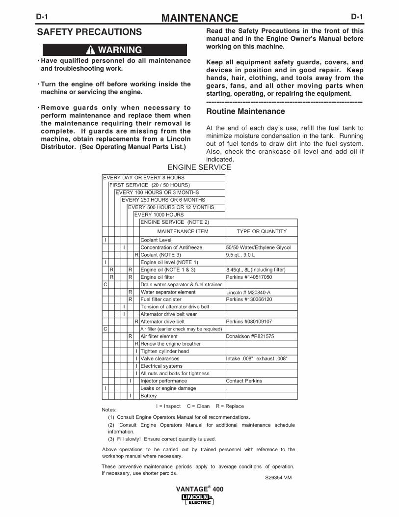
D-1MAINTENANCED-1
VANTAGE® 400
SAFETY PRECAUTIONS
• Have qualified personnel do all maintenanceand troubleshooting work.
• Turn the engine off before working inside themachine or servicing the engine.
• Remove guards only when necessary toperform maintenance and replace them whenthe maintenance requiring their removal iscomplete. If guards are missing from themachine, obtain replacements from a LincolnDistributor. (See Operating Manual Parts List.)
WARNING
Read the Safety Precautions in the front of thismanual and in the Engine Ownerʼs Manual beforeworking on this machine.
Keep all equipment safety guards, covers, anddevices in position and in good repair. Keephands, hair, clothing, and tools away from thegears, fans, and all other moving parts whenstarting, operating, or repairing the equipment.------------------------------------------------------------Routine Maintenance
At the end of each dayʼs use, refill the fuel tank tominimize moisture condensation in the tank. Runningout of fuel tends to draw dirt into the fuel system.Also, check the crankcase oil level and add oil ifindicated.
D-2MAINTENANCED-2
ENGINE OIL CHANGE
Drain the engine oil while the engine is warm to assurerapid and complete draining. It is recommended thateach time the oil is changed the oil filter be changed aswell.
• Be sure the unit is off. Disconnect the negative bat-tery cable to ensure safety.
• Locate oil drain hose and valve in bottom of baseand pull through the hole in the battery access panelon the welder.
• Open oil drain valve by lifting up spring loaded leverand rotate 90° counterclockwise. Pull to open anddrain the oil into a suitable container for disposal.
• Close the drain valve by rotating lever 90° clockwise.
• Re-fill the crankcase to the upper limit mark on thedipstick with the recommended oil (see engine oper-ation manual OR engine service items decal ORbelow). Replace and tighten the oil filler cap secure-ly.
• Push oil drain hose and valve back into unit, re-con-nect negative battery cable, and close doors andengine top cover before restarting unit.Wash yourhands with soap and water after handling used motoroil. Please dispose of used motor oil in a mannerthat is compatible with the environment. We suggestyou take it in a sealed container to your local servicestation or recycling center for reclamation. DO NOTthrow it in the trash; pour it on the ground or down adrain.
Use motor oil designed for diesel engines that meetsrequirements for API service classif icationCC/CD/CE/CF/CF-4/CG-4 or CH-4.
ACEA E1/E2/E3. Always check the API service labelon the oil container to be sure it includes the lettersindicated. (Note: An S-grade oil must not be used in adiesel engine or damage may result. It IS permissibleto use an oil that meets S and C grade service classifi-cations.)
SAE 10W30 is recommended for general, all tempera-ture use, 5F to 104F (-15C to 40C).
See engine ownerʼs manual for more specific informa-tion on oil viscosity recommendations.
OIL FILTER CHANGE
• Drain the oil.
• Remove the oil filter with an oil filter wrench anddrain the oil into a suitable container. Discard theused filter. Note: Care should be taken during filterremoval to not disrupt or damage in any way the fuellines.
• Clean the filter mounting base and coat the gasketof the new filter with clean engine oil.
• Screw the new filter on by hand until the gasket con-tacts the mounting base. Using an oil filter wrench,tighten the filter an additional 1/2 to 7/8 of a turn.
• Refill the crankcase with the specified amount of therecommended engine oil. Reinstall the oil filler capand tighten securely.
• Start the engine and check for oil filter leaks.
• Stop the engine and check the oil level. If neces-sary, add oil to the upper limit mark on the dipstick.
• Never use gasoline or low flash point solventsfor cleaning the air cleaner element. A fire orexplosion could result.
• Never run the engine without the air cleaner.Rapid engine wear will result from contaminants,such as dust and dirt being drawn into theengine.
------------------------------------------------------------------------AIR CLEANER
The diesel engine is equipped with a dry type air filter.Never apply oil to it. Service the air cleaner as follows:
Replace the element every 500 hours of operation.Under dusty conditions, replace sooner.
VANTAGE® 400
CAUTION
WARNING
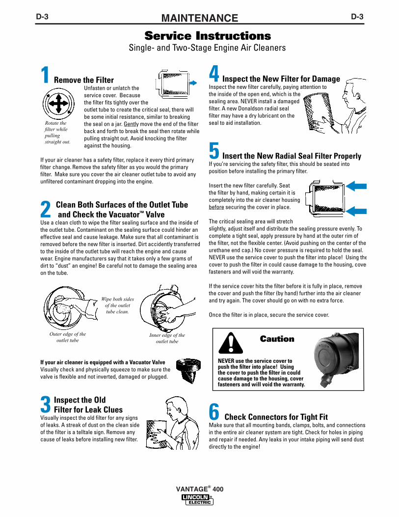
D-3MAINTENANCED-3
VANTAGE® 400
D-4MAINTENANCED-4
COOLING SYSTEM
HOT COOLANT can burn skin.
• Do not remove cap if radiator ishot.
------------------------------------------------------------------------Check the coolant level by observing the level in theradiator and recovery bottle. Add 50/50 antifreeze /water solution if the level is close to or below the"LOW" mark. do not fill above the "FULL" mark.Remove radiator cap and add coolant to radiator. Fillup to the top of the tube in the radiator filler neckwhich includes a connecting hose coming from thethermostat housing.
To drain the coolant, open the valve at the bottom ofthe radiator. Open the radiator cap to allow completedrainage. (Tighten the valve and refill with a 50/50antifreeze/water solution.) Use an automotive grade(low silicate) ethylene glycol antifreeze. The coolingsystem capacity is 8.0 quarts (7.6L.). Squeeze upperand lower radiator hoses while filling to bleed air fromsystem coolant. Replace and tighten the radiator cap.
Always premix the antifreeze and clean tap waterbefore adding to the radiator. It is very importantthat a precise 50/50 solution be used with thisengine year round. This gives proper cooling dur-ing hot weather and freezing protection to -34° F (-37° C).
Cooling solution exceeding 50% ethylene glycolcan result in engine overheating and damage tothe engine. Coolant solution must be premixedbefore adding to radiator.------------------------------------------------------------------------Periodically remove the dirt from the radiator fins.Periodically check the fan belt and radiator hoses.Replace if signs of deterioration are found.
TIGHTENING THE FAN BELT
If the fan belt is loose, the engine can overheat andthe battery lose its charge. Check tightness by press-ing on the belt midway between the pulleys. It shoulddeflect about .25 in.(6.4 mm) under a load of 20 lbs.(9Kg).
FUELDIESEL FUEL ONLY-Low sulphur fuel or ultralow sulphur fuel in U.S.A. and Canada.
At the end of each dayʼs use, refill the fuel tank to min-imize moisture condensation and dirt contamination inthe fuel line. Do not overfill; leave room for the fuel toexpand.
Use only fresh No. 2D diesel fuel, the use of No. 1Ddiesel fuel is recommended in place of No. 2D at tem-peratures below 23°F (-5°C). Do not use kerosene.
See the Engine Operator's Manual for instructions onreplacing the fuel filter.
BLEEDING THE FUEL SYSTEM
You may need to bleed air from the fuel system if thefuel filter or fuel lines have been detached, the fueltank has been ran empty or after periods of long stor-age. It is recommended that the fuel shutoff valve beclosed during periods of non-use.
To avoid personal injury, do not bleed a hotengine. This could cause fuel to spill onto a hotexhaust manifold, creating a danger of fire.------------------------------------------------------------------------Bleed the fuel system as follows:
1. Fill the fuel tank with fuel.2. Open the fuel shut off valve.3. Loosen bleed fitting on the fuel injector manifold.4. Operate hand priming lever until fuel comes out the
bleed screw on the injector manifold. This couldtake 20-30 seconds of rapid operation of the prim-ing lever. Tighten bleed fitting on injector manifold.
5. Follow normal STARTING procedures until enginestarts.
VANTAGE® 400
WARNING
CAUTION
WARNING

D-5MAINTENANCED-5
FUEL FILTER1. Check the fuel filter and fuel pre-filter for water
accumulation or sediment.
2. Replace the fuel filter if it is found with excessivewater accumulation or sediment. Empty fuel pre-fil-ter.
ENGINE ADJUSTMENTAdjustments to the engine are to be made only by aLincoln Service Center or an authorized Field ServiceShop.
BATTERY MAINTENANCETo access the battery, remove the battery tray fromthe front of the machine with 3/8” nut driver or flathead screw driver. Pull the tray out of machine farenough to disconnect the negative and then positivebattery cables. The tray can then be tilted and lifted toremove the entire tray and battery from the machinefor easy service.
GASES FROM BATTERY can explode.● Keep sparks, flame and cigarettes
away from battery.
To prevent EXPLOSION when:● INSTALLING A NEW BATTERY — disconnect
negative cable from old battery first and con-nect to new battery last.
● CONNECTING A BATTERY CHARGER —remove battery from welder by disconnectingnegative cable first, then positive cable andbattery clamp. When reinstalling, connectnegative cable last. Keep well ventilated.
● USING A BOOSTER — connect positive lead tobattery first then connect negative lead to neg-
ative battery lead at engine foot.BATTERY ACID can burn eyes andskin.● Wear gloves and eye protection
and be careful when working nearbattery.
● Follow instructions printed on battery.
VANTAGE® 400
OVERSPEED IS HAZARDOUSThe maximum allowable high idle speed for thismachine is 1890 RPM, no load. Do NOT tamperwith governor components or setting or make anyother adjustments to increase the maximumspeed. Severe personal injury and damage to themachine can result if operated at speeds abovemaximum.
CLEANING THE BATTERYKeep the battery clean by wiping it with a damp clothwhen dirty. If the terminals appear corroded, discon-nect the battery cables and wash the terminals with anammonia solution or a solution of 1/4 pound (0.1113kg) of baking soda and 1 quart (0.9461L) of water. Besure the battery vent plugs (if equipped) are tight sothat none of the solution enters the cells.After cleaning, flush the outside of the battery, the bat-tery compartment, and surrounding areas with clearwater. Coat the battery terminals lightly with petroleumjelly or a non-conductive grease to retard corrosion.Keep the battery clean and dry. Moisture accumula-tion on the battery can lead to more rapid dischargeand early battery failure.
CHECKING THE ELECTROLYTE LEVEL
If battery cells are low, fill them to the neck of the fillerhole with distilled water and recharge. If one cell islow, check for leaks.
CHARGING THE BATTERYWhen you charge, jump, replace, or otherwise con-nect battery cables to the battery, be sure the polarityis correct. Improper polarity can damage the chargingcircuit. The VANTAGE 400 positive (+) battery termi-nal has a red terminal cover.
If you need to charge the battery with an externalcharger, disconnect the negative cable first, then thepositive cable before you attach the charger leads.After the battery is charged, reconnect the positivebattery cable first and the negative cable last. Failureto do so can result in damage to the internal chargercomponents.Follow the instructions of the battery charger manu-facturer for proper charger settings and charging time.
SERVICING OPTIONAL SPARKARRESTORClean every 100 hours.
WARNING
WARNING
• MUFFLER MAY BE HOT
• ALLOW ENGINE TO COOL BEFORE INSTALLINGTHE SPARK ARRESTER!
• DO NOT OPERATE ENGINE WHILE INSTALLINGTHE SPARK ARRESTER!

D-6MAINTENANCED-6
VANTAGE® 400
WELDER / GENERATORMAINTENANCE
STORAGE: Store in clean, dry protected areas.
CLEANING: Blow out the generator and controls peri-odically with low pressure air. Do this at least once aweek in particularly dirty areas.
BRUSH REMOVAL AND REPLACEMENT: Itʼs nor-mal for the brushes and slip rings to wear and darkenslightly. Inspect the brushes when a generator over-haul is necessary.
• Do not attempt to polish slip rings while theengine is running.
GFCI RECEPTACLE TESTING AND RESET-TING PROCEDURE
The GFCI receptacle should be properly tested atleast once every month or whenever it is tripped. Toproperly test and reset the GFCI receptacle:
• If the receptacle has tripped, first carefully removeany load and check it for damage.
• If the equipment has been shut down, it must berestarted.
• The equipment needs to be operating at high idlespeed and any necessary adjustments made on thecontrol panel so that the equipment is providing atleast 80 volts to the receptacle input terminals.
• The circuit breaker for this receptacle must not betripped. Reset if necessary.
• Push the "Reset" button located on the GFCI recep-tacle. This will assure normal GFCI operation.
• Plug a night-light (with an "ON/OFF" switch) or otherproduct (such as a lamp) into the GFCI receptacleand turn the product "ON".
• Push the "Test" button located on the GFCI recepta-cle. The night-light or other product should go"OFF".
• Push the "Reset" button, again. The light or otherproduct should go "ON" again.
If the light or other product remains "ON" when the"Test" button is pushed, the GFCI is not working prop-erly or has been incorrectly installed (miswired). Ifyour GFCI is not working properly, contact a qualified,certified electrician who can assess the situation,rewire the GFCI if necessary or replace the device.
WARNING
• Service and Repair should only be performed byLincoln Electric Factory Trained Personnel.Unauthorized repairs performed on this equip-ment may result in danger to the technician andmachine operator and will invalidate your factorywarranty. For your safety and to avoid ElectricalShock, please observe all safety notes and pre-cautions.
CAUTION

E-1TROUBLESHOOTINGE-1
VANTAGE® 400
If for any reason you do not understand the test procedures or are unable to perform the tests/repairs safely, contact yourLocal Lincoln Authorized Field Service Facility for technical troubleshooting assistance before you proceed.
CAUTION
This Troubleshooting Guide is provided to help youlocate and repair possible machine malfunctions.Simply follow the three-step procedure listed below.
Step 1. LOCATE PROBLEM (SYMPTOM).Look under the column labeled “PROBLEM (SYMP-TOMS)”. This column describes possible symptomsthat the machine may exhibit. Find the listing thatbest describes the symptom that the machine isexhibiting.
Step 2. POSSIBLE CAUSE.The second column labeled “POSSIBLE CAUSE” liststhe obvious external possibilities that may contributeto the machine symptom.
Step 3. RECOMMENDED COURSE OF ACTIONThis column provides a course of action for thePossible Cause, generally it states to contact yourlocal Lincoln Authorized Field Service Facility.
If you do not understand or are unable to perform theRecommended Course of Action safely, contact yourlocal Lincoln Authorized Field Service Facility.
HOW TO USE TROUBLESHOOTING GUIDE
Service and Repair should only be performed by Lincoln Electric Factory Trained Personnel.Unauthorized repairs performed on this equipment may result in danger to the technician andmachine operator and will invalidate your factory warranty. For your safety and to avoid ElectricalShock, please observe all safety notes and precautions detailed throughout this manual.
__________________________________________________________________________
WARNING
E-2TROUBLESHOOTINGE-2
VANTAGE 400
Observe all Safety Guidelines detailed throughout this manual
If for any reason you do not understand the test procedures or are unable to perform the tests/repairs safely, contact yourLocal Lincoln Authorized Field Service Facility for technical troubleshooting assistance before you proceed.
CAUTION
PROBLEMS(SYMPTOMS)
POSSIBLECAUSE
RECOMMENDEDCOURSE OF ACTION
Major Physical or Electrical Damageis Evident.
Engine will not "crank".
Engine will "crank" but not start.
Engine shuts down shortly afterstarting.
1. Contact your local LincolnAuthorized Field ServiceFacility.
1. Battery is low, Charge Battery.2. Loose battery cable connections.
Inspect, clean and tighten terminals.3. Faulty engine starter motor.
Contact authorized local EngineService Shop.
1. Fuel shut off valve on Main FuelFilter in the OFF position. Openvalve (vertical) position of handle.
2. Fuel Filters dirty/clogged. Checkand replace main filter elementand/or Inline Fuel Filter.
3. Out of fuel. Fill tank and bleed fuelsystem.
4. High coolant temperature or lowoil pressure. (indictor lights lit)Check oil and coolant levels. Fill ifrequired. Check for loose or bro-ken fan belt.
5. Faulty fuel shutdown solenoid.Check that shutdown solenoid isfunctioning properly and not bind-ing/ contact authorized engineservice shop.
6. Faulty fuel pump. Check for fuelflow through filters. Contact autho-rized local Engine Service Shop.
1. High coolant temperature or lowoil pressure. (indictor light lit)Change oil and oil filters and fill toproper level. Check and fill coolantlevel. Check for loose or brokenfan belt. Start engine and look forleaks.
2. Faulty oil pressure switch or otherengine component. Contactauthorized local Engine ServiceShop.
3. Faulty Idler/Protection Board.
If all recommended possible areasof misadjustment have beenchecked and the problem persists,Contact your local LincolnAuthorized Field Service Facility.
E-3TROUBLESHOOTINGE-3Observe all Safety Guidelines detailed throughout this manual
If for any reason you do not understand the test procedures or are unable to perform the tests/repairs safely, contact yourLocal Lincoln Authorized Field Service Facility for technical troubleshooting assistance before you proceed.
CAUTION
PROBLEMS(SYMPTOMS)
POSSIBLECAUSE
RECOMMENDEDCOURSE OF ACTION
Engine shuts down while under aload.
Engine runs rough.
Battery does not stay charged.Engine alternator trouble light is onwhile machine is running.
Engine will not idle down to lowspeed.
Engine will not go to high idle whenattempting to weld.
1. High radiator coolant tempera-ture. Reduce load if it is exceed-ing machine rating. Add coolantto system if low. Clean fins onradiator if dirty. Tighten fan belt ifloose. Remove objects blockingor close to intake openings onboth sides of base and exhaustend (case back).
1. Dirty fuel or air filters. Inspect andclean/replace filters as needed.Inspect and clean/replace filtersas needed.
2. Water in fuel. If water found intank. Empty fuel tank and refillthen purge fuel lines.
1. Faulty battery. Replace.2. Loose connections at battery or
alternator. Clean and tighten con-nections.
3. Faulty engine alternator or charg-er module. Consult authorizedEngine Service Shop.
1. Idler switch in High idle position.Set switch to Auto.
2. External load on welder or auxil-iary power. Remove all externalloads.
3. Faulty PC board or idler sole-noid.
1. Poor work lead connection towork. Make sure work clamp istightly connected to clean basemetal.
2. "Contactor" switch is in wrongposition. Set to "Welding On" whenwelding without a control cable.Refer to Operations chapter for prop-er use of this switch.
3. Faulty PC board. Low idle speedset to low.
If all recommended possible areas ofmisadjustment have been checkedand the problem persists, Contactyour local Lincoln AuthorizedField Service Facility.
VANTAGE® 400
E-4TROUBLESHOOTINGE-4
VANTAGE® 400
Observe all Safety Guidelines detailed throughout this manual
If for any reason you do not understand the test procedures or are unable to perform the tests/repairs safely, contact yourLocal Lincoln Authorized Field Service Facility for technical troubleshooting assistance before you proceed.
CAUTION
PROBLEMS(SYMPTOMS)
POSSIBLECAUSE
RECOMMENDEDCOURSE OF ACTION
Engine will not go to high idle whenusing auxiliary power.
Engine wil l not go to high idleunder weld or auxiliary loading.
Engine does not develop fullpower. Engine runs rough.
Engine will not go to high idle whenattempting to weld or using auxil-iary power. Switching to manualhigh idle does not work.
Engine will not shut off.
Engine does not develop full power.Low weld and auxil iary output.Engine runs rough.
1. Auxiliary power load is less than100 watts. Idler may not respondwith less than a 100 watt load. Setidler to "High".
2. Faulty PC board.(Control or Idler).
1. Faulty idler solenoid. Check forbent linkage or broken spring.
2. Faulty PC board.(Control or Idler).
1. Fuel filter clogged, Replace.2. Air filter clogged, clean or replace.3. High idle setting incorrect, check
and adjust if required.4. Valves out of adjustment.5. Fuel contaminated with water or
sediment. Check fuel pre-filterand empty of water, bleed fuelsystem. Replace fuel in tank ifneeded.
1. Broken spring on Idle Solenoid,solenoid linkage binding, FaultyPC board (Control or Idler), lowidle speed set too low on idlesolenoid.
1. Fuel Shutdown solenoid not func-tioning properly / linkage binding.Stop engine by shutting off valvelocated on main fuel filter. Contactauthorized local Engine ServiceShop.
1. Fuel filter dirty/clogged. Replace.2. Air filter dirty/clogged. Replace Air
Filter Element.3. Fouled fuel injector(s). Contact
authorized Engine Service Shop.4. Fuel contaminated with water.
Check water separator for water.Clean and replace as needed.Replace fuel in tank.
5. Cracked or loose fuel hose.Replace hose and tighten clamps.
6. Valves out of adjustment. Contactauthorized local Engine ServiceShop.
If all recommended possible areasof misadjustment have beenchecked and the problem persists,Contact your local LincolnAuthorized Field Service Facility.

E-5TROUBLESHOOTINGE-5
VANTAGE® 400
Observe all Safety Guidelines detailed throughout this manual
If for any reason you do not understand the test procedures or are unable to perform the tests/repairs safely, contact yourLocal Lincoln Authorized Field Service Facility for technical troubleshooting assistance before you proceed.
CAUTION
PROBLEMS(SYMPTOMS)
POSSIBLECAUSE
RECOMMENDEDCOURSE OF ACTION
No welding power output.
Welder has output but no control.
Wire feeder does not work whencontrol cable is connected to 14 pinconnector.
No auxiliary power.
1. Poor work lead connection towork. Make sure work clamp istightly connected to clean basemetal.
2. "Weld Terminals" switch in wrongposition. Place switch in "WeldTerminals On" posit ion whenwelding without control cable.
3. Faulty PC board or welder alterna-tor.
1. Poor remote/control cable connec-tion to 6-pin or 14-pin connector.Check connections.
2. Faulty remote cable or faulty wirefeeder or wire feeder cable.Replace if necessary.
3. Faulty control potentiometer or PCboard.
1. Wire Feeder Power circuit breakeropen. Check 42V and 120Vbeakers and reset if tripped.
2. Faulty control cable. Repair orreplace cable.
3. Faulty wire feeder. Replace wirefeeder.
1. GFCI Receptacle may havetripped. Follow “GFCI ReceptacleTesting and Resetting Procedure”in the MAINTENANCE section ofthis manual.
2. Faulty connections to auxiliaryreceptacles. Check connections.
3. Faulty PC board or welder alterna-tor.
If all recommended possible areasof misadjustment have beenchecked and the problem persists,Contact your local LincolnAuthorized Field Service Facility.

E-6TROUBLESHOOTINGE-6Observe all Safety Guidelines detailed throughout this manual
If for any reason you do not understand the test procedures or are unable to perform the tests/repairs safely, contact yourLocal Lincoln Authorized Field Service Facility for technical troubleshooting assistance before you proceed.
CAUTION
PROBLEMS(SYMPTOMS)
POSSIBLECAUSE
RECOMMENDEDCOURSE OF ACTION
The welding arc is “cold.” The weld-ing arc is not stable or is not satis-factory. the engine runs normally.The auxiliary power is normal.
No output in Pipe Mode.
VRD Lights donʼt light up.
1. Make sure the MODE selectorswitch is in the correct position forthe process being used. (For exam-ple, CV-WIRE, PIPE, CC-STICK.)
2. Make sure the electrode (wire, gas,voltage, current etc.) is correct forthe process being used.
3. Check for loose or faulty connec-tions at the weld output terminalsand welding cable connections.
4. The welding cables may be too longor coiled, causing an excessivevoltage drop.
5. Faulty Control Board.
1. Make sure VRD ON/OFF toggleswitch is in the “OFF” position.
2. Poor work lead connection towork. Make sure work clamp istightly connected to clean basemetal.
3. "Weld Terminals" switch in wrongposition. Place switch in "WeldTerminals On" posit ion whenwelding without control cable.
4. Faulty PC board or welder alterna-tor.
1. Ensure VRD ON/OFF switch is inthe “ON” position.
2. If light is burned out, replace bothVRD lights.
3. Faulty OCV indicator PC board.
If all recommended possible areas ofmisadjustment have been checkedand the problem persists, Contactyour local Lincoln AuthorizedField Service Facility.
VANTAGE® 400

F-1DIAGRAMSF-1
VANTAGE® 400

F-2DIAGRAMSF-2
VANTAGE® 400

F-3DIAGRAMSF-3
VANTAGE® 400
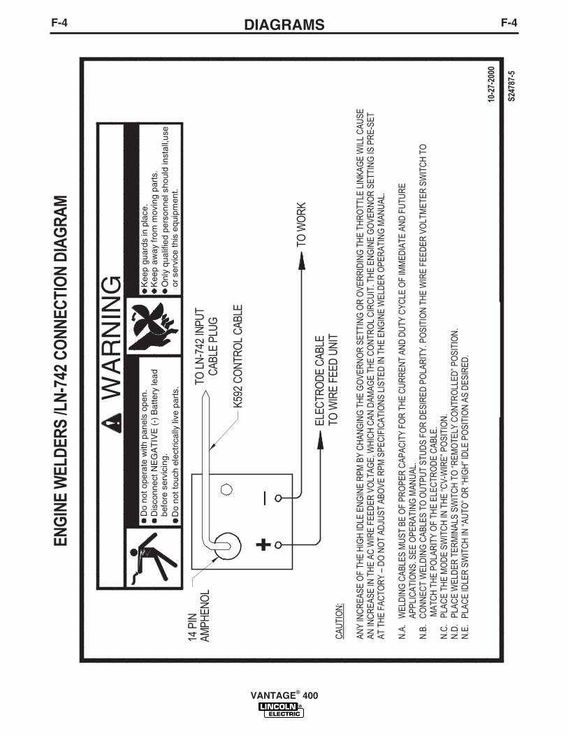
F-4DIAGRAMSF-4
VANTAGE® 400

F-5DIAGRAMSF-5
VANTAGE® 400
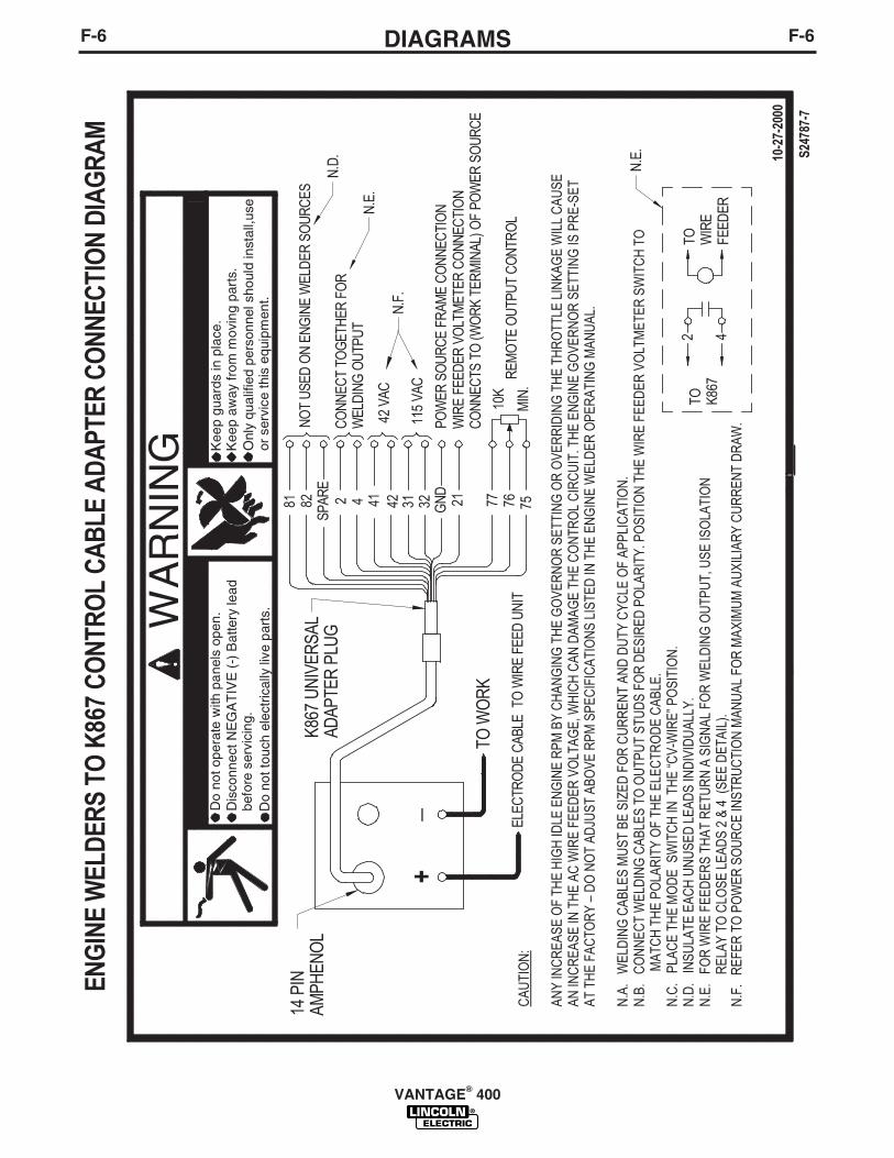
F-6DIAGRAMSF-6
VANTAGE® 400
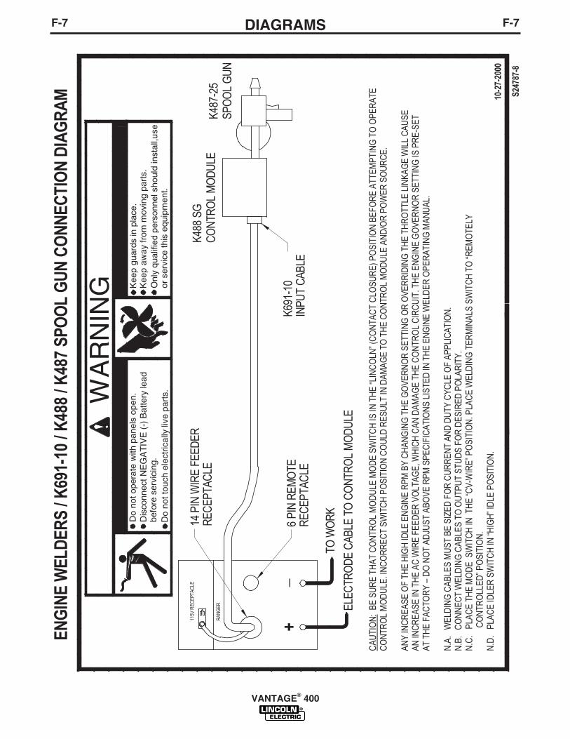
F-7DIAGRAMSF-7
VANTAGE® 400
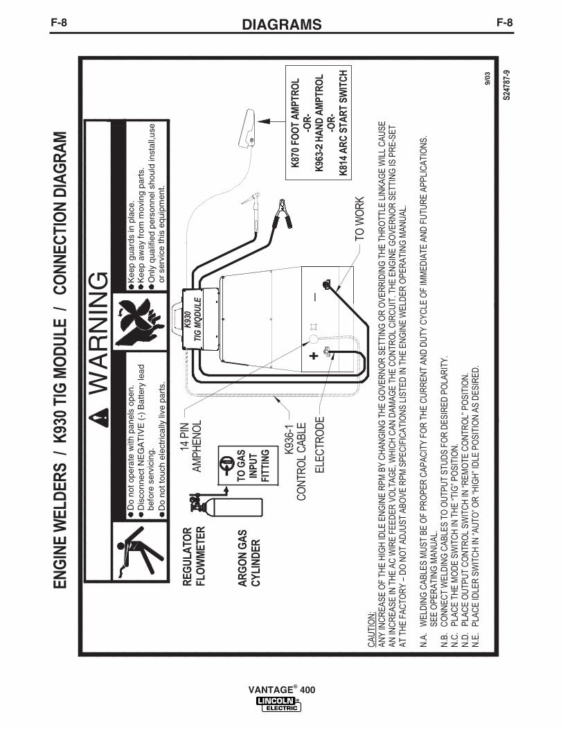
F-8DIAGRAMSF-8
VANTAGE® 400
2
9/03

F-9DIAGRAMSF-9
VANTAGE® 400

F-10WIRING DIAGRAMF-10
VANTAGE® 400
NO
TE
: T
his
dia
gra
m is
fo
r re
fere
nce
on
ly.
It m
ay n
ot
be
accu
rate
fo
r al
l mac
hin
es c
ove
red
by
this
man
ual
. T
he
spec
ific
dia
gra
m f
or
a p
arti
cula
r co
de
is in
clu
ded
wit
h t
he
mac
hin
e. I
f th
e d
iag
ram
is il
leg
ible
, wri
te t
o t
he
Ser
vice
Dep
artm
ent
for
a re
pla
cem
ent.
Giv
e th
e eq
uip
men
t co
de
nu
mb
er.
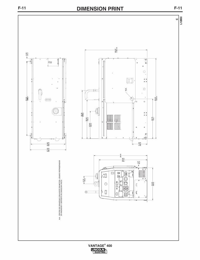
F-11DIMENSION PRINTF-11
VANTAGE® 400
L12853C
25.8
265
5.8
27.0
068
5.8
55.5
014
0914
09..7
2.25
57.2
5.75
146.
0
35.9
491
3.0
24.0
060
9.6
39.8
1
20.6
052
3.3
28.9
573
5.3
36.0
691
591
5.9
29.7
575
5.7
60.0
015
24.0
11.2
528
5.8
N.A
.
N.A
. C
EN
TR
O D
E G
RA
VE
DA
D C
ON
AC
EIT
E E
N M
OT
OR
, LÍQ
UID
O R
EF
RIG
ER
AD
OR
EN
RA
DIA
DO
R Y
DE
PÓ
SIT
O D
E G
AS
OLI
NA
VA
CÍO
.
1.27
32.3
46.6
211
84.1
5
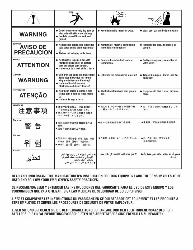
WARNING
AVISO DEPRECAUCION
ATTENTION
WARNUNG
ATENÇÃO
Spanish
French
German
Portuguese
Japanese
Chinese
Korean
Arabic
READ AND UNDERSTAND THE MANUFACTURER’S INSTRUCTION FOR THIS EQUIPMENT AND THE CONSUMABLES TO BEUSED AND FOLLOW YOUR EMPLOYER’S SAFETY PRACTICES.
SE RECOMIENDA LEER Y ENTENDER LAS INSTRUCCIONES DEL FABRICANTE PARA EL USO DE ESTE EQUIPO Y LOSCONSUMIBLES QUE VA A UTILIZAR, SIGA LAS MEDIDAS DE SEGURIDAD DE SU SUPERVISOR.
LISEZ ET COMPRENEZ LES INSTRUCTIONS DU FABRICANT EN CE QUI REGARDE CET EQUIPMENT ET LES PRODUITS AETRE EMPLOYES ET SUIVEZ LES PROCEDURES DE SECURITE DE VOTRE EMPLOYEUR.
LESEN SIE UND BEFOLGEN SIE DIE BETRIEBSANLEITUNG DER ANLAGE UND DEN ELEKTRODENEINSATZ DES HER-STELLERS. DIE UNFALLVERHÜTUNGSVORSCHRIFTEN DES ARBEITGEBERS SIND EBENFALLS ZU BEACHTEN.
● Do not touch electrically live parts orelectrode with skin or wet clothing.
● Insulate yourself from work andground.
● No toque las partes o los electrodosbajo carga con la piel o ropa moja-da.
● Aislese del trabajo y de la tierra.
● Ne laissez ni la peau ni des vête-ments mouillés entrer en contactavec des pièces sous tension.
● Isolez-vous du travail et de la terre.
● Berühren Sie keine stromführendenTeile oder Elektroden mit IhremKörper oder feuchter Kleidung!
● Isolieren Sie sich von denElektroden und dem Erdboden!
● Não toque partes elétricas e elec-trodos com a pele ou roupa molha-da.
● Isole-se da peça e terra.
● Keep flammable materials away.
● Mantenga el material combustiblefuera del área de trabajo.
● Gardez à l’écart de tout matérielinflammable.
● Entfernen Sie brennbarres Material!
● Mantenha inflamáveis bem guarda-dos.
● Wear eye, ear and body protection.
● Protéjase los ojos, los oídos y elcuerpo.
● Protégez vos yeux, vos oreilles etvotre corps.
● Tragen Sie Augen-, Ohren- und Kör-perschutz!
● Use proteção para a vista, ouvido ecorpo.

WARNING
AVISO DEPRECAUCION
ATTENTION
WARNUNG
ATENÇÃO
Spanish
French
German
Portuguese
Japanese
Chinese
Korean
Arabic
LEIA E COMPREENDA AS INSTRUÇÕES DO FABRICANTE PARA ESTE EQUIPAMENTO E AS PARTES DE USO, E SIGA ASPRÁTICAS DE SEGURANÇA DO EMPREGADOR.
● Keep your head out of fumes.● Use ventilation or exhaust to
remove fumes from breathing zone.
● Los humos fuera de la zona de res-piración.
● Mantenga la cabeza fuera de loshumos. Utilice ventilación oaspiración para gases.
● Gardez la tête à l’écart des fumées.● Utilisez un ventilateur ou un aspira-
teur pour ôter les fumées des zonesde travail.
● Vermeiden Sie das Einatmen vonSchweibrauch!
● Sorgen Sie für gute Be- undEntlüftung des Arbeitsplatzes!
● Mantenha seu rosto da fumaça.● Use ventilação e exhaustão para
remover fumo da zona respiratória.
● Turn power off before servicing.
● Desconectar el cable de ali-mentación de poder de la máquinaantes de iniciar cualquier servicio.
● Débranchez le courant avantl’entretien.
● Strom vor Wartungsarbeitenabschalten! (Netzstrom völlig öff-nen; Maschine anhalten!)
● Não opere com as tampas removidas.● Desligue a corrente antes de fazer
serviço.● Não toque as partes elétricas nuas.
● Do not operate with panel open orguards off.
● No operar con panel abierto oguardas quitadas.
● N’opérez pas avec les panneauxouverts ou avec les dispositifs deprotection enlevés.
● Anlage nie ohne Schutzgehäuseoder Innenschutzverkleidung inBetrieb setzen!
● Mantenha-se afastado das partesmoventes.
● Não opere com os paineis abertosou guardas removidas.

• Sales and Service through Subsidiaries and Distributors Worldwide •
Cleveland, Ohio 44117-1199 U.S.A. TEL: 216.481.8100 FAX: 216.486.1751 WEB SITE: www.lincolnelectric.com
• World's Leader in Welding and Cutting Products •