im hp protectus iii.book
TRANSCRIPT

E-C
od
E-C
od
HP PROTECTUS® III Installation and Maintenance Guide
HP
PRO
TEC
TUS®
III I
NST
ALL
ATI
ON
AN
D M
AIN
TEN
AN
CE
GU
IDE


HP PROTECTUS® III Installation and Maintenance Guide

Copyright
This manual is an unpublished work and contains the trade secrets and confidential information of Neptune Technology Group Inc., which are not to be divulged to third parties and may not be reproduced or transmitted in whole or part, in any form or by any means, electronic or mechanical for any purpose, without the express written permission of Neptune Technology Group Inc. All rights to designs or inventions disclosed herein, including the right to manufacture, are reserved to Neptune Technology Group Inc.
Neptune engages in ongoing research and development to improve and enhance its products. Therefore, Neptune reserves the right to change product or system specifications without notice.
Trademarks used in this manual
HP PROTECTUS III is a registered trademark of Neptune Technology Group Inc. T-10 is a registered trademark of Neptune Technology Group Inc. E-Coder is a registered trademark of Neptune Technology Group Inc. E-Coder)R900i is a trademark of Neptune Technology Group Inc.
Other brands or product names are the trademarks or registered trademarks of their respective holders.
Professional Installation
In accordance with section 15.203 of the FCC rules and regulations, the MIU must be professionally installed by trained utility meter installers. Changes or modifications not expressly approved by the party responsible for compliance could void the user's authority to operate the equipment.
Changes or modifications not expressly approved by the party responsible for compliance couldvoid the user's authority to operate the equipment.
HP PROTECTUS® III Installation and Maintenance Guide
Literature No. IM HP PROTECTUS III 11.15
Part No. 13505-021
Neptune Technology Group Inc.
1600 Alabama Highway 229
Tallassee, AL 36078
Tel: (800) 633-8754
Fax: (334) 283-7293Copyright © 2015
Neptune Technology Group Inc.
All Rights Reserved.

Contents
1 Introduction
Product Description . . . . . . . . . . . . . . . . . . . . . . . . . . . . . . . . . . . . . . . . . . . . . . . . . . . . . . . . . . . . . . . . . . . . . 1
Components . . . . . . . . . . . . . . . . . . . . . . . . . . . . . . . . . . . . . . . . . . . . . . . . . . . . . . . . . . . . . . . . . . . . . . . . . . 2
Turbine Measuring Element . . . . . . . . . . . . . . . . . . . . . . . . . . . . . . . . . . . . . . . . . . . . . . . . . . . . . . . . . . . 2
T-10 Bypass . . . . . . . . . . . . . . . . . . . . . . . . . . . . . . . . . . . . . . . . . . . . . . . . . . . . . . . . . . . . . . . . . . . . . . . 2
Throttle Valve . . . . . . . . . . . . . . . . . . . . . . . . . . . . . . . . . . . . . . . . . . . . . . . . . . . . . . . . . . . . . . . . . . . . . . 2
Knuckle Valve. . . . . . . . . . . . . . . . . . . . . . . . . . . . . . . . . . . . . . . . . . . . . . . . . . . . . . . . . . . . . . . . . . . . . . 2
UL/FM Basket Strainer . . . . . . . . . . . . . . . . . . . . . . . . . . . . . . . . . . . . . . . . . . . . . . . . . . . . . . . . . . . . . . . 3
HP PROTECTUS III General Information . . . . . . . . . . . . . . . . . . . . . . . . . . . . . . . . . . . . . . . . . . . . . . . . . . . . 3
Operation . . . . . . . . . . . . . . . . . . . . . . . . . . . . . . . . . . . . . . . . . . . . . . . . . . . . . . . . . . . . . . . . . . . . . . . . . 3
Construction . . . . . . . . . . . . . . . . . . . . . . . . . . . . . . . . . . . . . . . . . . . . . . . . . . . . . . . . . . . . . . . . . . . . . . . 3
Warranty. . . . . . . . . . . . . . . . . . . . . . . . . . . . . . . . . . . . . . . . . . . . . . . . . . . . . . . . . . . . . . . . . . . . . . . . . . 4
2 Specifications
Environmental Specifications . . . . . . . . . . . . . . . . . . . . . . . . . . . . . . . . . . . . . . . . . . . . . . . . . . . . . . . . . . . . . 5
HP PROTECTUS III Operating Characteristics. . . . . . . . . . . . . . . . . . . . . . . . . . . . . . . . . . . . . . . . . . . . . . . . 5
HP PROTECTUS III Dimensions. . . . . . . . . . . . . . . . . . . . . . . . . . . . . . . . . . . . . . . . . . . . . . . . . . . . . . . . . . . 6
3 Installing the HP PROTECTUS III
Prior to Installation. . . . . . . . . . . . . . . . . . . . . . . . . . . . . . . . . . . . . . . . . . . . . . . . . . . . . . . . . . . . . . . . . . . . . . 9
Storage. . . . . . . . . . . . . . . . . . . . . . . . . . . . . . . . . . . . . . . . . . . . . . . . . . . . . . . . . . . . . . . . . . . . . . . . . . . 9
Unpacking . . . . . . . . . . . . . . . . . . . . . . . . . . . . . . . . . . . . . . . . . . . . . . . . . . . . . . . . . . . . . . . . . . . . . . . . 9
Tools Needed . . . . . . . . . . . . . . . . . . . . . . . . . . . . . . . . . . . . . . . . . . . . . . . . . . . . . . . . . . . . . . . . . . . . . . 9
Safety and Preliminary Checks . . . . . . . . . . . . . . . . . . . . . . . . . . . . . . . . . . . . . . . . . . . . . . . . . . . . . . . 10
Installing the HP PROTECTUS III . . . . . . . . . . . . . . . . . . . . . . . . . . . . . . . . . . . . . . . . . . . . . . . . . . . . . . . . . 10
Installing Strainer . . . . . . . . . . . . . . . . . . . . . . . . . . . . . . . . . . . . . . . . . . . . . . . . . . . . . . . . . . . . . . . . . . 10
Recommended Installation. . . . . . . . . . . . . . . . . . . . . . . . . . . . . . . . . . . . . . . . . . . . . . . . . . . . . . . . . . . 10
Adjusting the Calibration Vane . . . . . . . . . . . . . . . . . . . . . . . . . . . . . . . . . . . . . . . . . . . . . . . . . . . . . . . . 12
Before Operation . . . . . . . . . . . . . . . . . . . . . . . . . . . . . . . . . . . . . . . . . . . . . . . . . . . . . . . . . . . . . . . . . . 12
HP PROTECTUS III Installation and Maintenance Guide iii

Contents
4 Maintaining the HP PROTECTUS III
Neptune’s UME Design . . . . . . . . . . . . . . . . . . . . . . . . . . . . . . . . . . . . . . . . . . . . . . . . . . . . . . . . . . . . . . . . . 15
Performing Maintenance on the Meter . . . . . . . . . . . . . . . . . . . . . . . . . . . . . . . . . . . . . . . . . . . . . . . . . . . . . 16
Low Side - T-10 . . . . . . . . . . . . . . . . . . . . . . . . . . . . . . . . . . . . . . . . . . . . . . . . . . . . . . . . . . . . . . . . . . . 16
Reassemble the T-10 . . . . . . . . . . . . . . . . . . . . . . . . . . . . . . . . . . . . . . . . . . . . . . . . . . . . . . . . . . . . 18
High Side - HP Turbine . . . . . . . . . . . . . . . . . . . . . . . . . . . . . . . . . . . . . . . . . . . . . . . . . . . . . . . . . . . . . 21
Inspect the Basket Strainer . . . . . . . . . . . . . . . . . . . . . . . . . . . . . . . . . . . . . . . . . . . . . . . . . . . . . . . . . . 22
Flush the Strainer Body . . . . . . . . . . . . . . . . . . . . . . . . . . . . . . . . . . . . . . . . . . . . . . . . . . . . . . . . . . 23
Knuckle Valve. . . . . . . . . . . . . . . . . . . . . . . . . . . . . . . . . . . . . . . . . . . . . . . . . . . . . . . . . . . . . . . . . . . . . 25
Removing the Knuckle Valve . . . . . . . . . . . . . . . . . . . . . . . . . . . . . . . . . . . . . . . . . . . . . . . . . . . . . . 26
Setting the Spring of the Knuckle Valve . . . . . . . . . . . . . . . . . . . . . . . . . . . . . . . . . . . . . . . . . . . . . . 27
Installing the New Knuckle Valve . . . . . . . . . . . . . . . . . . . . . . . . . . . . . . . . . . . . . . . . . . . . . . . . . . . 28
5 Contacting Neptune Customer Support
By Phone . . . . . . . . . . . . . . . . . . . . . . . . . . . . . . . . . . . . . . . . . . . . . . . . . . . . . . . . . . . . . . . . . . . . . . . . . . . . 31
By Fax . . . . . . . . . . . . . . . . . . . . . . . . . . . . . . . . . . . . . . . . . . . . . . . . . . . . . . . . . . . . . . . . . . . . . . . . . . . . . . 31
By Email . . . . . . . . . . . . . . . . . . . . . . . . . . . . . . . . . . . . . . . . . . . . . . . . . . . . . . . . . . . . . . . . . . . . . . . . . . . . 31
A Detaching the Basket Strainer
Detach Basket Strainer . . . . . . . . . . . . . . . . . . . . . . . . . . . . . . . . . . . . . . . . . . . . . . . . . . . . . . . . . . . . . . . . . 33
Reassemble the Victaulic Coupling . . . . . . . . . . . . . . . . . . . . . . . . . . . . . . . . . . . . . . . . . . . . . . . . . . . . . . . . 35
B HP PROTECTUS III Parts List
HP PROTECTUS III . . . . . . . . . . . . . . . . . . . . . . . . . . . . . . . . . . . . . . . . . . . . . . . . . . . . . . . . . . . . . . . . . . . 37
Cover Assembly . . . . . . . . . . . . . . . . . . . . . . . . . . . . . . . . . . . . . . . . . . . . . . . . . . . . . . . . . . . . . . . . . . . . . . 39
Glossary
Index
iv HP PROTECTUS III Installation and Maintenance Guide

Figures
Figure Title Page
1 HP PROTECTUS III . . . . . . . . . . . . . . . . . . . . . . . . . . . . . . . . . . . . . . . . . . . . . . . . . . . . . . . . . . . .12 HP PROTECTUS III Side View . . . . . . . . . . . . . . . . . . . . . . . . . . . . . . . . . . . . . . . . . . . . . . . . . . . .63 HP PROTECTUS III Top View . . . . . . . . . . . . . . . . . . . . . . . . . . . . . . . . . . . . . . . . . . . . . . . . . . . .74 HP PROTECTUS III End View . . . . . . . . . . . . . . . . . . . . . . . . . . . . . . . . . . . . . . . . . . . . . . . . . . . .75 Calibration Vane . . . . . . . . . . . . . . . . . . . . . . . . . . . . . . . . . . . . . . . . . . . . . . . . . . . . . . . . . . . . . .126 Bleed Screw . . . . . . . . . . . . . . . . . . . . . . . . . . . . . . . . . . . . . . . . . . . . . . . . . . . . . . . . . . . . . . . . .127 Main Components of the HP PROTECTUS III . . . . . . . . . . . . . . . . . . . . . . . . . . . . . . . . . . . . . . .148 Unitized Measuring Element (UME) . . . . . . . . . . . . . . . . . . . . . . . . . . . . . . . . . . . . . . . . . . . . . . .159 Remove T-10 Bolts . . . . . . . . . . . . . . . . . . . . . . . . . . . . . . . . . . . . . . . . . . . . . . . . . . . . . . . . . . . .1610 Remove Register . . . . . . . . . . . . . . . . . . . . . . . . . . . . . . . . . . . . . . . . . . . . . . . . . . . . . . . . . . . . .1611 Remove T-10 Top Plate . . . . . . . . . . . . . . . . . . . . . . . . . . . . . . . . . . . . . . . . . . . . . . . . . . . . . . . .1712 T-10 Gasket . . . . . . . . . . . . . . . . . . . . . . . . . . . . . . . . . . . . . . . . . . . . . . . . . . . . . . . . . . . . . . . . .1713 Removing the T-10 Strainer . . . . . . . . . . . . . . . . . . . . . . . . . . . . . . . . . . . . . . . . . . . . . . . . . . . . .1714 T-10 Strainer . . . . . . . . . . . . . . . . . . . . . . . . . . . . . . . . . . . . . . . . . . . . . . . . . . . . . . . . . . . . . . . . .1715 T-10 Disc Chamber . . . . . . . . . . . . . . . . . . . . . . . . . . . . . . . . . . . . . . . . . . . . . . . . . . . . . . . . . . . .1816 Throttle Valve . . . . . . . . . . . . . . . . . . . . . . . . . . . . . . . . . . . . . . . . . . . . . . . . . . . . . . . . . . . . . . . .1817 Throttle Valve Push Button . . . . . . . . . . . . . . . . . . . . . . . . . . . . . . . . . . . . . . . . . . . . . . . . . . . . . .1818 Square O-ring . . . . . . . . . . . . . . . . . . . . . . . . . . . . . . . . . . . . . . . . . . . . . . . . . . . . . . . . . . . . . . . .1919 Inserting the Disc Chamber. . . . . . . . . . . . . . . . . . . . . . . . . . . . . . . . . . . . . . . . . . . . . . . . . . . . . .1920 Inserting the Strainer. . . . . . . . . . . . . . . . . . . . . . . . . . . . . . . . . . . . . . . . . . . . . . . . . . . . . . . . . . .1921 Inserting New Gasket . . . . . . . . . . . . . . . . . . . . . . . . . . . . . . . . . . . . . . . . . . . . . . . . . . . . . . . . . .2022 Cleaning the Top Plate . . . . . . . . . . . . . . . . . . . . . . . . . . . . . . . . . . . . . . . . . . . . . . . . . . . . . . . . .2023 Reinstalling the Top Plate . . . . . . . . . . . . . . . . . . . . . . . . . . . . . . . . . . . . . . . . . . . . . . . . . . . . . . .2024 Removing the Bolts from the HP Turbine Top Plate . . . . . . . . . . . . . . . . . . . . . . . . . . . . . . . . . . .2125 Remove Register from the HP Turbine . . . . . . . . . . . . . . . . . . . . . . . . . . . . . . . . . . . . . . . . . . . . .2126 Remove the HP Turbine Top Plate . . . . . . . . . . . . . . . . . . . . . . . . . . . . . . . . . . . . . . . . . . . . . . . .2127 UME Attached to HP Turbine Top Plate . . . . . . . . . . . . . . . . . . . . . . . . . . . . . . . . . . . . . . . . . . . .2228 Installing the Register . . . . . . . . . . . . . . . . . . . . . . . . . . . . . . . . . . . . . . . . . . . . . . . . . . . . . . . . . .2229 Strainer Top Plate . . . . . . . . . . . . . . . . . . . . . . . . . . . . . . . . . . . . . . . . . . . . . . . . . . . . . . . . . . . . .2230 Strainer Top Plate Hook . . . . . . . . . . . . . . . . . . . . . . . . . . . . . . . . . . . . . . . . . . . . . . . . . . . . . . . .2331 Basket Strainer . . . . . . . . . . . . . . . . . . . . . . . . . . . . . . . . . . . . . . . . . . . . . . . . . . . . . . . . . . . . . . .2332 Inspect Basket. . . . . . . . . . . . . . . . . . . . . . . . . . . . . . . . . . . . . . . . . . . . . . . . . . . . . . . . . . . . . . . .2333 Pipe Plug. . . . . . . . . . . . . . . . . . . . . . . . . . . . . . . . . . . . . . . . . . . . . . . . . . . . . . . . . . . . . . . . . . . .2334 Replace Basket . . . . . . . . . . . . . . . . . . . . . . . . . . . . . . . . . . . . . . . . . . . . . . . . . . . . . . . . . . . . . . .2435 Strainer Case O-Ring . . . . . . . . . . . . . . . . . . . . . . . . . . . . . . . . . . . . . . . . . . . . . . . . . . . . . . . . . .2436 Strainer Top Plate . . . . . . . . . . . . . . . . . . . . . . . . . . . . . . . . . . . . . . . . . . . . . . . . . . . . . . . . . . . . .2437 Secure the Strainer Top Plate. . . . . . . . . . . . . . . . . . . . . . . . . . . . . . . . . . . . . . . . . . . . . . . . . . . .2538 Knuckle Valve Top Plate . . . . . . . . . . . . . . . . . . . . . . . . . . . . . . . . . . . . . . . . . . . . . . . . . . . . . . . .2539 Remove Knuckle Valve Top Plate. . . . . . . . . . . . . . . . . . . . . . . . . . . . . . . . . . . . . . . . . . . . . . . . .2540 Knuckle Valve . . . . . . . . . . . . . . . . . . . . . . . . . . . . . . . . . . . . . . . . . . . . . . . . . . . . . . . . . . . . . . . .2541 Knuckle Valve Housing - Small Bolts . . . . . . . . . . . . . . . . . . . . . . . . . . . . . . . . . . . . . . . . . . . . . .26
HP PROTECTUS III Installation and Maintenance Guide v

Figures
Figure Title Page42 Inside the Knuckle Valve Housing. . . . . . . . . . . . . . . . . . . . . . . . . . . . . . . . . . . . . . . . . . . . . . . . .2643 Removing the Knuckle Valve . . . . . . . . . . . . . . . . . . . . . . . . . . . . . . . . . . . . . . . . . . . . . . . . . . . .2644 Cleaning the Knuckle Valve Housing . . . . . . . . . . . . . . . . . . . . . . . . . . . . . . . . . . . . . . . . . . . . . .2745 Knuckle Valve Bolt Holes . . . . . . . . . . . . . . . . . . . . . . . . . . . . . . . . . . . . . . . . . . . . . . . . . . . . . . .2746 Compressing the Knuckle Valve . . . . . . . . . . . . . . . . . . . . . . . . . . . . . . . . . . . . . . . . . . . . . . . . . .2747 Locking the Spring . . . . . . . . . . . . . . . . . . . . . . . . . . . . . . . . . . . . . . . . . . . . . . . . . . . . . . . . . . . .2848 Handling the Knuckle Valve Tool . . . . . . . . . . . . . . . . . . . . . . . . . . . . . . . . . . . . . . . . . . . . . . . . .2849 Rubber Disk Facing HP Turbine . . . . . . . . . . . . . . . . . . . . . . . . . . . . . . . . . . . . . . . . . . . . . . . . . .2850 Inserting New Bolts . . . . . . . . . . . . . . . . . . . . . . . . . . . . . . . . . . . . . . . . . . . . . . . . . . . . . . . . . . . .2951 Remove Knuckle Valve Tool . . . . . . . . . . . . . . . . . . . . . . . . . . . . . . . . . . . . . . . . . . . . . . . . . . . . .2952 Knuckle Valve O-ring . . . . . . . . . . . . . . . . . . . . . . . . . . . . . . . . . . . . . . . . . . . . . . . . . . . . . . . . . .2953 Secure the Knuckle Valve Top Plate. . . . . . . . . . . . . . . . . . . . . . . . . . . . . . . . . . . . . . . . . . . . . . .3054 Victaulic Coupling . . . . . . . . . . . . . . . . . . . . . . . . . . . . . . . . . . . . . . . . . . . . . . . . . . . . . . . . . . . . .3355 Remove Bolts . . . . . . . . . . . . . . . . . . . . . . . . . . . . . . . . . . . . . . . . . . . . . . . . . . . . . . . . . . . . . . . .3356 Loosen Coupling . . . . . . . . . . . . . . . . . . . . . . . . . . . . . . . . . . . . . . . . . . . . . . . . . . . . . . . . . . . . . .3457 Victaulic Coupling Gasket . . . . . . . . . . . . . . . . . . . . . . . . . . . . . . . . . . . . . . . . . . . . . . . . . . . . . . .3458 Separate Strainer from HP Turbine. . . . . . . . . . . . . . . . . . . . . . . . . . . . . . . . . . . . . . . . . . . . . . . .3459 New Gasket. . . . . . . . . . . . . . . . . . . . . . . . . . . . . . . . . . . . . . . . . . . . . . . . . . . . . . . . . . . . . . . . . .3560 Reattach Victaulic Coupling . . . . . . . . . . . . . . . . . . . . . . . . . . . . . . . . . . . . . . . . . . . . . . . . . . . . .3561 Tighten Bolts . . . . . . . . . . . . . . . . . . . . . . . . . . . . . . . . . . . . . . . . . . . . . . . . . . . . . . . . . . . . . . . . .3562 Representative Breakdown of the HP PROTECTUS III . . . . . . . . . . . . . . . . . . . . . . . . . . . . . . . .3763 Representative Breakdown of the Cover Assembly . . . . . . . . . . . . . . . . . . . . . . . . . . . . . . . . . . .39
vi HP PROTECTUS III Installation and Maintenance Guide

Tables
Table Title Page
1 Environmental Specifications . . . . . . . . . . . . . . . . . . . . . . . . . . . . . . . . . . . . . . . . . . . . . . . . .52 Operating Characteristics . . . . . . . . . . . . . . . . . . . . . . . . . . . . . . . . . . . . . . . . . . . . . . . . . . . . 53 HP PROTECTUS III Dimensions - Side View . . . . . . . . . . . . . . . . . . . . . . . . . . . . . . . . . . . . . 64 HP PROTECTUS III Dimensions - Top and End View . . . . . . . . . . . . . . . . . . . . . . . . . . . . . . 75 Meter Registration (Per One Revolution of the Sweep Hand). . . . . . . . . . . . . . . . . . . . . . . . . 86 Maximum Dial Face Capacity (Six-Wheel Odometer) . . . . . . . . . . . . . . . . . . . . . . . . . . . . . . . 87 Tools Needed for Installation. . . . . . . . . . . . . . . . . . . . . . . . . . . . . . . . . . . . . . . . . . . . . . . . . . 98 HP PROTECTUS III Parts List . . . . . . . . . . . . . . . . . . . . . . . . . . . . . . . . . . . . . . . . . . . . . . . 389 Cover Assembly Parts . . . . . . . . . . . . . . . . . . . . . . . . . . . . . . . . . . . . . . . . . . . . . . . . . . . . . . 39
HP PROTECTUS III Installation and Maintenance Guide vii

Tables
Notes:
viii HP PROTECTUS III Installation and Maintenance Guide
1 Introduction
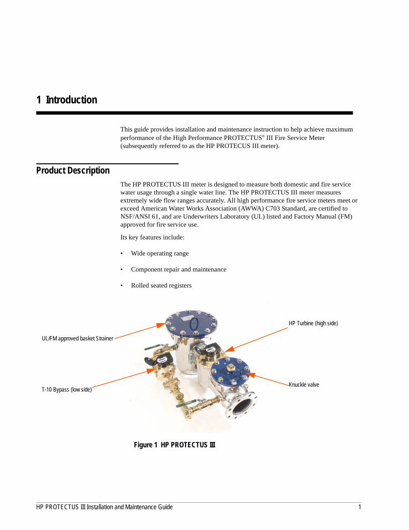
This guide provides installation and maintenance instruction to help achieve maximum performance of the High Performance PROTECTUS® III Fire Service Meter (subsequently referred to as the HP PROTECUS III meter).
Product DescriptionThe HP PROTECTUS III meter is designed to measure both domestic and fire service water usage through a single water line. The HP PROTECTUS III meter measures extremely wide flow ranges accurately. All high performance fire service meters meet or exceed American Water Works Association (AWWA) C703 Standard, are certified to NSF/ANSI 61, and are Underwriters Laboratory (UL) listed and Factory Manual (FM) approved for fire service use.
Its key features include:
• Wide operating range
• Component repair and maintenance
• Rolled seated registers
Figure 1 HP PROTECTUS III
UL/FM approved basket Strainer
T-10 Bypass (low side)
HP Turbine (high side)
Knuckle valve
HP PROTECTUS III Installation and Maintenance Guide 1

Introduction
ComponentsThe HP PROTECTUS III has five primary measurement components.
• Turbine measuring element
• T-10® bypass meter
• Throttle valve located inside the T-10 bypass meter
• Knuckle valve
• UL/FM Strainer
Turbine Measuring ElementFigure 8 on page 15 shows the turbine measuring assembly removed from the meter. Key components of the turbine measuring element are:
• O-ring assembly that seals the measuring element
• Turbine/rotor
The turbine measuring element sits in front of the knuckle valve. It is designed to handle medium to high flow.
T-10 BypassFigure 1 on page 1 shows the T-10 bypass on the left side of the assembly. The T-10 bypass meter is designed to capture the low flow that passes through the HP PROTECTUS III. When the flow rate is low, the water hits the knuckle valve located behind the turbine but it is not strong enough to overcome the spring force of the knuckle valve. Therefore, it is diverted through the T-10 on the bypass.
Throttle ValveThe T-10 bypass meter contains a throttle valve in the meter outlet. See Figure 16 on page 18. The throttle valve is used to regulate the amount of flow that is passing through the T-10 bypass. The valve serves to protect the T-10 from seeing excessive usage, and facilitates the meter’s transition through cross over.
Knuckle ValveThe knuckle valve sits behind the turbine measuring element. The knuckle valve is a rubber faced disc that is held closed with linkages. When the flow rate is low, the water does not have enough force to overcome the knuckle valve. The water hits the face of the knuckle valve and is diverted to the T-10 bypass. As the flow rate increases the water begins to push the knuckle valve open.
You must not replace the T-10 on a HP PROTECTUS III bypass with a T-10 meter that does not have the throttle valve installed in the T-10 outlet. You need to make sure the throttle valve is present in the outlet of the meter that is used as a replacement.
2 HP PROTECTUS III Installation and Maintenance Guide

Introduction
When the water is increasing in flow rate and the knuckle valve is transitioning from closed to open, the meter is transitioning through a state know as crossover. After transitioning through cross over, the meter is in a medium to high flow range. The T-10 bypass continues to constantly measure flow. The T-10 bypass should always be registering some flow as long as the flow rate is above the T-10’s minimum operating rate. The turbine measuring element can register flow when the rate is medium to high.
UL/FM Basket StrainerThe Strainer in the HP PROTECTUS III meter is a UL/FM-approved Strainer specially designed to handle fire service applications. The round style of the Strainer allows debris to fall to the bottom of the Strainer housing. This is significant, because the meter must be able to deliver the flow rate required for a fire situation even if debris has entered the meter. By having the debris fall to the bottom of the Strainer housing, it keeps the debris out of the line of the flow and does not obstruct a large flow. The basket can be removed and cleaned when necessary. There is also an o-ring seal between the cover and the body to protect against leaking. See Figure 35 on page 24.
HP PROTECTUS III General InformationThe following sections provide general information about the HP PROTECTUS III meter.
OperationAt low flow rates, all flow is through the bypass meter. As flow increases, pressure loss through the bypass meter increases, and the knuckle valve opens. This condition occurs, for example, when a fire sprinkler system goes into operation. This permits flow through the main turbine meter. As flow decreases, reduced pressure loss closes the knuckle valve, and flow is again directed through the bypass meter.
ConstructionThe HP PROTECTUS III meter consists of:
• Stainless steel mainline body
• Knuckle valve (rubber-faced, stainless steel spring-loaded type)
• Stainless Strainer body with stainless steel basket
• HP Turbine measuring element
• Bronze bypass assembly
• Lockable ball valves used on bypass
• Throttle valve
• 1-inch T-10 meter (on 4 inch size)
• 1.5-inch T-10 or 1.5-inch HP Turbine meter (on 6-inch sizes)
• 2-inch T-10 or 2-inch HP Turbine meter (on 8-inch and 10-inch sizes)
HP PROTECTUS III Installation and Maintenance Guide 3

Introduction
WarrantyNeptune provides a limited warranty with respect to its HP PROTECTUS III meters for performance, materials and workmanship.
The stainless steel body is warranted for 20 years. Ten of which are prorated.
Neptune fire service cold water meters perform, for a period of one year from date of shipment, to AWWA accuracy standards for new water meters.
When desired, owner maintenance is easily accomplished by inline replacement of major components, or a factory-calibrated Unitized Measuring Element (UME).
4 HP PROTECTUS III Installation and Maintenance Guide

2 Specifications
This chapter describes the specifications, operating characteristics, and dimensions for the HP PROTECTUS III meter.
Environmental SpecificationsThis section contains environmental specifications for the HP PROTECTUS III meter.
HP PROTECTUS III Operating CharacteristicsThis section provides a table of the operating characteristics of the HP PROTECTUS III meter.
Table 1 Environmental Specifications
Application Cold water measurement of flow in one direction
Maximum Operating Pressure 175 psi (1206 kPa)
Table 2 Operating Characteristics
Meter SizeNormal Operating Range @100% Accuracy (±1.5%) AWWA Standard
Low Flow@95% Accuracy
Maximum IntermittentFlow Rate
4 inch 3/4 to 1200 US gpm0.17 to 272.55 m3/h
4 to 700 US gpm0.91 to 1.59 m3/h
3/8 US gpm0.09 m3/h
1500 US gpm340.7 m3/h
6 inch 1 1/2 to 2500 US gpm0.34 to 567.81 m3/h
5 to 1600 US gpm1.14 to 363 m3/h
3/4 US gpm0.17 m3/h
3100 US gpm704.1 m3/h
8 inch 2 to 4000 US gpm0.45 to 908.5 m3/h
8 to 2800 US gpm1.8 to 636 m3/h
1 US gpm0.23 m3/h
5000 US gpm1135.6 m3/h
10 inch 2 to 6500 US gpm0.45 to 1476.31 m3/h
8 to 4400 US gpm1.8 to 999 m3/h
1 US gpm0.23 m3/h
8000 US gpm1817 m3/h
HP PROTECTUS III Installation and Maintenance Guide 5

Specifications
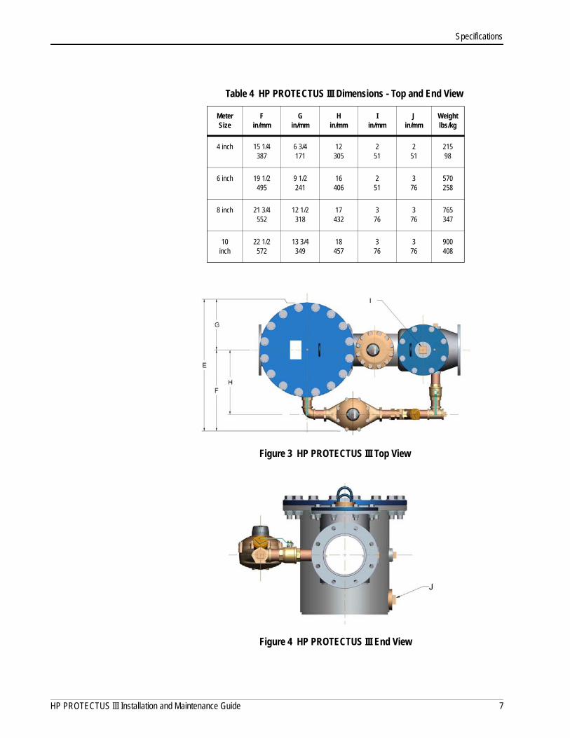
HP PROTECTUS III DimensionsThis section provides the dimensions, diagrams, and registration of the HP PROTECTUS III meter. Use the following table to read the dimensions of the HP PROTECTUS III.
Figure 2, Figure 3 on page 7, and Figure 4 on page 7 demonstrate the dimensions for the HP PROTECTUS III meter.
Figure 2 HP PROTECTUS III Side View
Table 3 HP PROTECTUS III Dimensions - Side View
Meter Size
Ain/mm
Bin/mm
Cin/mm
D in/mm
Weightlbs/kg
4 inch 33838
10254
10 3/4273
17 1/2445
21598
6 inch 451143
11 1/16281
11 3/8289
21 1/4540
570258
8 inch 531346
11 13/16300
13 29/64342
25 7/8657
765347
10 inch
681727
14 13/16376
15381
30 1/16764
900408
6 HP PROTECTUS III Installation and Maintenance Guide
Specifications
Figure 3 HP PROTECTUS III Top View
Figure 4 HP PROTECTUS III End View
Table 4 HP PROTECTUS III Dimensions - Top and End View
Meter Size
Fin/mm
Gin/mm
Hin/mm
Iin/mm
Jin/mm
Weightlbs/kg
4 inch 15 1/4387
6 3/4171
12305
251
251
21598
6 inch 19 1/2495
9 1/2241
16406
251
376
570258
8 inch 21 3/4552
12 1/2318
17432
376
376
765347
10 inch
22 1/2572
13 3/4349
18457
376
376
900408
HP PROTECTUS III Installation and Maintenance Guide 7

Specifications
Table 5 Meter Registration (Per One Revolution of the Sweep Hand)
US Gallon Imperial Gallon Cubic Feet Cubic Meters
Disc Side
1 inch 10 10 1 0.1
1 1/2 inch 100 100 10 1
2 inch 100 100 10 1
Turbine Side
4 inch 100 100 10 1
6 inch 1,000 1,000 100 10
8 inch 1,000 1,000 100 10
10 inch 1,000 1,000 100 10
Table 6 Maximum Dial Face Capacity (Six-Wheel Odometer)
US Gallon Imperial Gallon Cubic Feet Cubic Meters
Disc Side
1 inch 10,000,000 10,000,000 1,000,000 100,000
1 1/2 inch 100,000,000 100,000,000 10,000,000 1,000,000
2 inch 100,000,000 100,000,000 10,000,000 1,000,000
Turbine Side
4 inch 100,000,000 100,000,000 10,000,000 1,000,000
6 inch 1,000,000,000 1,000,000,000 100,000,000 10,000,000
8 inch 1,000,000,000 1,000,000,000 100,000,000 10,000,000
10 inch 1,000,000,000 1,000,000,000 100,000,000 10,000,000
8 HP PROTECTUS III Installation and Maintenance Guide

3 Installing the HP PROTECTUS III
This chapter is designed to step you through the installation process for the HP PROTECTUS III meter.
Prior to Installation
StorageUpon receipt, inspect shipping containers for damage and inspect the contents of any damaged cartons prior to storage.
Once the inspection is complete, store the cartons in a clean, dry environment.
Unpacking
After unpacking the HP PROTECTUS III meter, inspect it for damage. If the meter appears to be damaged, notify your Neptune Territory Manager or distributor. If one or more items requires reshipment, use the original cardboard box and packing material.
Tools Needed Table 7 shows the recommended tools you need to successfully install the HP PROTECTUS III meter.
Do not lift the assembly by a single center strap around the meter body, or by either end alone.
Table 7 is not a complete list of tools and materials.
Table 7 Tools Needed for Installation
Part Number Description
N/A Contains standard tools including:• Flathead Screwdriver• Hammer• Pliers• 7/16-inch Wrench
HP PROTECTUS III Installation and Maintenance Guide 9
Installing the HP PROTECTUS III
Safety and Preliminary ChecksComplete the following safety and preliminary checks before and during each installation:
• Verify that you are at the location specified on the site work order.
• Verify that the site is safe for you and your equipment.
Installing the HP PROTECTUS IIIThe HP PROTECTUS III meter operates more accurately and reliably if installed and maintained properly. HP PROTECTUS III meter performance is directly related to the flow conditions of the water entering the turbine portion of the meter. Four pipe diameters of straight pipe are needed in front of and behind the meter.
Installing StrainerThe HP PROTECTUS III meter assembly includes the required UL-listed and FM-approved basket-type Strainer in front of the fire service turbine and bypass. The Strainer, in addition to protecting the meter from debris in the line, also corrects the velocity profile of the flow to the turbine meter, and minimizes the effects of upstream piping variations. Proper service and cleaning of the Strainer is important for long term reliability and performance of the turbine measuring element.
When installing Neptune HP PROTECTUS III, a minimum of four pipe diameters of straight run pipe can include components that are fully open in their normal operating position. This is required upstream and downstream of the meter/Strainer assembly.
Recommended Installation
The HP PROTECTUS III meter assembly can be lowered into the meter vault and put in place by chains or straps. The chains or straps can be attached to the lifting hooks on the top of both the Strainer and knuckle valve.
5500-153, 154, 155 Tool to remove knuckle valve also called Valve Retainer Tool (size dependent)
Table 7 Tools Needed for Installation
Part Number Description
10 HP PROTECTUS III Installation and Maintenance Guide

Installing the HP PROTECTUS III
The recommended installation of the HP PROTECTUS III is in a horizontal position with its arrow pointing in the direction of the water flow. The HP PROTECTUS III bypass meter can be installed on either side of the mainline meter. Prior to installation, inspect the knuckle valve to make sure the valve is fully seated and the face is undamaged. A full-size bypass around the assembly is recommended, because it provides uninterrupted service capability during meter servicing periods.
As indicated previously, the required UL-listed and FM-approved Strainer provides protection against meter damage from rocks and debris in the lines and virtually eliminates the effects of variation in upstream piping.
A test port is provided on the top of the knuckle valve section to allow a means to field test the meter without removing it from the line.
The HP PROTECTUS III meter assembly must operate in a completely filled line at all times. The downstream piping must always provide sufficient back pressure to maintain a full line at the meter.
Do not lift the assembly by a single center strap around the meter body or by either end alone.
When installing an HP PROTECTUS III meter assembly, follow normal good piping practices. In particular, centrally locate all gaskets on their flanges with no overlap or interference with the pipe diameter.
The Strainer basket can be separated from the T-10 and HP Turbine for easier installation in a pit or basement. See Appendix A on page 33.
HP PROTECTUS III Installation and Maintenance Guide 11

Installing the HP PROTECTUS III
Adjusting the Calibration VaneNeptune equips all new turbine meters and UMEs with a calibration vane. If field calibration of the turbine element is required, complete the following steps.
1 Remove the seal pin from the register and twist off the register.
2 Loosen lock nut on adjusting stem by turning counter-clockwise.
3 Insert slotted screwdriver into slot in top of adjusting stem and do one of the following.
• Turn the adjusting stem toward the plus sign (+) to increase registration.
• Turn the adjusting stem toward the minus sign (-) to decrease the registration.
Figure 5 Calibration Vane
Before OperationBefore putting the HP PROTECTUS III meter assembly into service, complete the following steps.
1 Close all valves.
2 Turn the air bleed screw on the knuckle valve and stainer cover counter-clockwise one to two turns. See Figure 6.
3 Open slowly the mainline inlet side gate valve to pressurize the meter.
With the bleed screw open, you begin to hear air vent from the open bleed screw.
Figure 6 Bleed Screw
4 Wait until water begins to run from the bleed screw and does not sputter out.
This helps to vent some of the air before opening the downstream valve.
Turning the adjustment stem 15 degrees in either direction results in approximately one percent change in registration. The full range of the calibration vane is 180 degrees.
bleed screw
12 HP PROTECTUS III Installation and Maintenance Guide

Installing the HP PROTECTUS III
5 Close bleed screw (clockwise) on top of the meter.
6 Open slowly the outlet side gate valve until the downstream line is pressurized.
7 Open slowly the upstream ball valve on the bypass to pressurize the bypass meter.
8 Open slowly the downstream ball valve on the bypass.
There is still a high chance for entrapped air and the downstream valve should be opened slowly.
After installation, it is important that the upstream (inlet) valve is put in the full-open position during service.
HP PROTECTUS III Installation and Maintenance Guide 13
4 Maintaining the HP PROTECTUS III
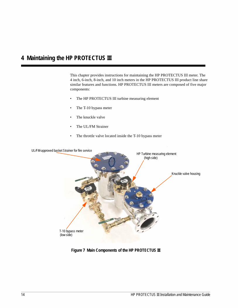
This chapter provides instructions for maintaining the HP PROTECTUS III meter. The 4 inch, 6-inch, 8-inch, and 10 inch meters in the HP PROTECTUS III product line share similar features and functions. HP PROTECTUS III meters are composed of five major components:
• The HP PROTECTUS III turbine measuring element
• The T-10 bypass meter
• The knuckle valve
• The UL/FM Strainer
• The throttle valve located inside the T-10 bypass meter
Figure 7 Main Components of the HP PROTECTUS III
HP Turbine measuring element
T-10 bypass meter
UL/FM-approved basket Strainer for fire service
Knuckle valve housing
(low side)
(high side)
14 HP PROTECTUS III Installation and Maintenance Guide
Maintaining the HP PROTECTUS III
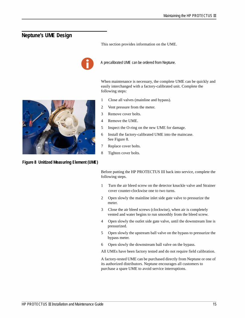
Neptune’s UME Design
This section provides information on the UME.
When maintenance is necessary, the complete UME can be quickly and easily interchanged with a factory-calibrated unit. Complete the following steps:
1 Close all valves (mainline and bypass).
2 Vent pressure from the meter.
3 Remove cover bolts.
4 Remove the UME.
5 Inspect the O-ring on the new UME for damage.
6 Install the factory-calibrated UME into the maincase. See Figure 8.
7 Replace cover bolts.
8 Tighten cover bolts.
Figure 8 Unitized Measuring Element (UME)
Before putting the HP PROTECTUS III back into service, complete the following steps.
1 Turn the air bleed screw on the detector knuckle valve and Strainer cover counter-clockwise one to two turns.
2 Open slowly the mainline inlet side gate valve to pressurize the meter.
3 Close the air bleed screws (clockwise), when air is completely vented and water begins to run smoothly from the bleed screw.
4 Open slowly the outlet side gate valve, until the downstream line is pressurized.
5 Open slowly the upstream ball valve on the bypass to pressurize the bypass meter.
6 Open slowly the downstream ball valve on the bypass.
All UMEs have been factory tested and do not require field calibration.
A factory-tested UME can be purchased directly from Neptune or one of its authorized distributors. Neptune encourages all customers to purchase a spare UME to avoid service interruptions.
A precalibrated UME can be ordered from Neptune.
HP PROTECTUS III Installation and Maintenance Guide 15
Maintaining the HP PROTECTUS III
Performing Maintenance on the MeterThis section provides information on maintaining the HP PROTECTUS III meter.
There are two sides to the HP PROTECTUS III meter.
• Low side - T-10
• High side - HP Turbine
Each side has its own register. The T-10 receives a T-10 register and the HP Turbine receives a HP PROTECTUS III register.
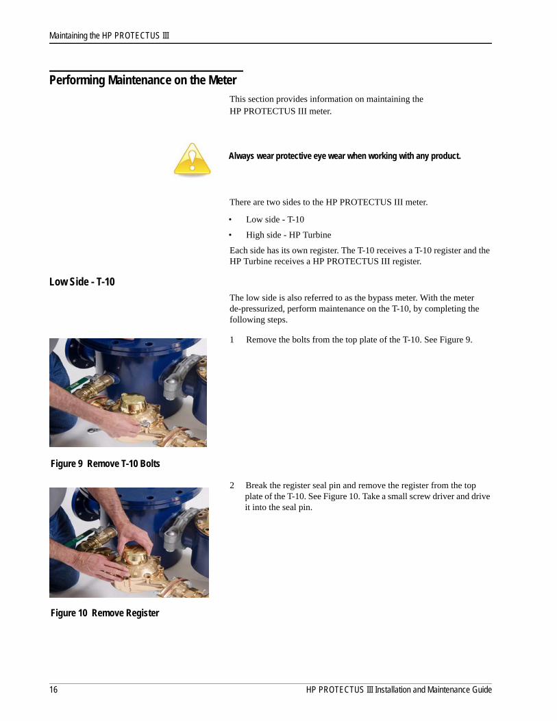
Low Side - T-10The low side is also referred to as the bypass meter. With the meter de-pressurized, perform maintenance on the T-10, by completing the following steps.
1 Remove the bolts from the top plate of the T-10. See Figure 9.
Figure 9 Remove T-10 Bolts
2 Break the register seal pin and remove the register from the top plate of the T-10. See Figure 10. Take a small screw driver and drive it into the seal pin.
Figure 10 Remove Register
Always wear protective eye wear when working with any product.
16 HP PROTECTUS III Installation and Maintenance Guide

Maintaining the HP PROTECTUS III
3 Remove the top plate of the T-10. See Figure 11.
Figure 11 Remove T-10 Top Plate
4 Remove the gasket from the T-10 and discard if damaged. See Figure 12.
Figure 12 T-10 Gasket
5 Remove the T-10 Strainer.
• Insert the screw driver between the Strainer and disc chamber and lift straight up. Tabs are located on top of the strainer to make removal of the strainer easier. Wedge the screwdriver underneath these tabs and lift the strainer straight up.See Figure 13.
• Inspect the Strainer and remove any debris. See Figure 14.
Figure 13 Removing the T-10 Strainer
Figure 14 T-10 Strainer
Strainer
HP PROTECTUS III Installation and Maintenance Guide 17

Maintaining the HP PROTECTUS III
6 Remove the T-10 disc chamber by lifting it straight up. See Figure 15.
The throttle valve is exposed. See Figure 16.
Figure 15 T-10 Disc Chamber
7 Inspect the throttle valve for damage (broken spring) and replace if needed.
Figure 16 Throttle Valve
Reassemble the T-10
Complete the following steps to reassemble the T-10 meter.
1 Reinstall the throttle valve. The push button on the throttle valve faces the inlet side and slides into the outlet of the meter. See Figure 17.
Figure 17 Throttle Valve Push Button
A replacement T-10 body does not include the throttle valve. Purchase one of the following:
• New T-10 with the throttle already installed, P/N 12001-000, 12001-100, or 12001-200 depending on size.
• Standalone new throttle valve, P/N 11668-000, 11668-100, or 11668-200 depending on size.
p
Push
button
18 HP PROTECTUS III Installation and Maintenance Guide

Maintaining the HP PROTECTUS III
2 Replace the square o-ring on the disc chamber. See Figure 18.
Figure 18 Square O-ring
3 Lower the disc chamber into the T-10 meter. See Figure 19.
Figure 19 Inserting the Disc Chamber
4 Insert the disc Strainer. Line it up with the notches inside the meter and make sure it is flush. See Figure 20.
Figure 20 Inserting the Strainer
O-ring
HP PROTECTUS III Installation and Maintenance Guide 19
Maintaining the HP PROTECTUS III
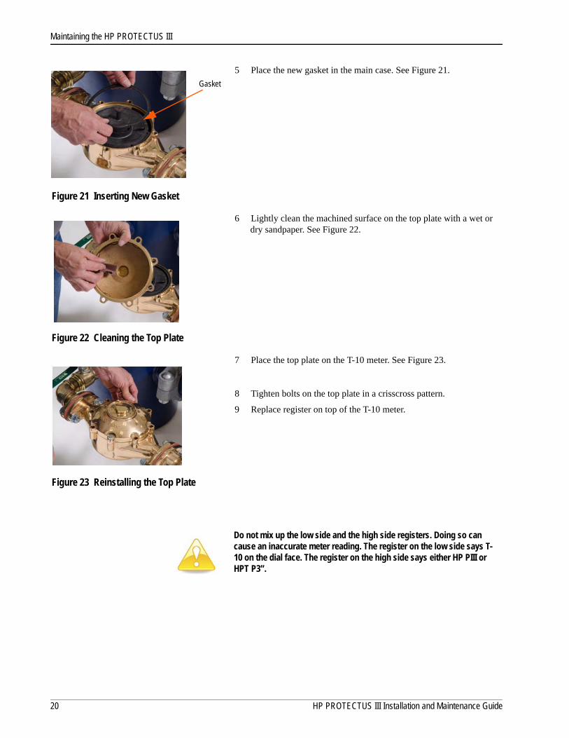
5 Place the new gasket in the main case. See Figure 21.
Figure 21 Inserting New Gasket
6 Lightly clean the machined surface on the top plate with a wet or dry sandpaper. See Figure 22.
Figure 22 Cleaning the Top Plate
7 Place the top plate on the T-10 meter. See Figure 23.
8 Tighten bolts on the top plate in a crisscross pattern.
9 Replace register on top of the T-10 meter.
Figure 23 Reinstalling the Top Plate
Do not mix up the low side and the high side registers. Doing so can cause an inaccurate meter reading. The register on the low side says T-10 on the dial face. The register on the high side says either HP PIII or HPT P3”.
Gasket
20 HP PROTECTUS III Installation and Maintenance Guide

Maintaining the HP PROTECTUS III
High Side - HP TurbineTo perform maintenance on the HP Turbine, complete the following steps.
1 Remove the bolts from the top plate of the HP Turbine. See Figure 24.
Figure 24 Removing the Bolts from the HP Turbine Top Plate
2 Break the register seal pin and remove the register from the top plate of the Turbine. Take a small screwdriver and drive it into the seal pin. See Figure 25.
Figure 25 Remove Register from the HP Turbine
3 Place a screw driver under the HP Turbine cover, in the slots provided to pop the top, and lift upwards to remove the cover. See Figure 26.
Figure 26 Remove the HP Turbine Top Plate
To prevent the epoxy coat from chipping when installing bolts, place a washer on top of and under the bolt holes.
HP PROTECTUS III Installation and Maintenance Guide 21
Maintaining the HP PROTECTUS III
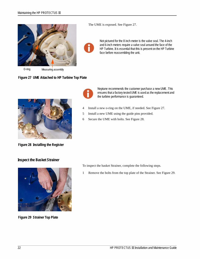
The UME is exposed. See Figure 27.
Figure 27 UME Attached to HP Turbine Top Plate
4 Install a new o-ring on the UME, if needed. See Figure 27.
5 Install a new UME using the guide pins provided.
6 Secure the UME with bolts. See Figure 28.
Figure 28 Installing the Register
Inspect the Basket StrainerTo inspect the basket Strainer, complete the following steps.
1 Remove the bolts from the top plate of the Strainer. See Figure 29.
Figure 29 Strainer Top Plate
Not pictured for the 8 inch meter is the valve seal. The 4-inch and 6-inch meters require a valve seal around the face of the HP Turbine. It is essential that this is present on the HP Turbine face before reassembling the unit.
Neptune recommends the customer purchase a new UME. This ensures that a factory tested UME is used as the replacement and the turbine performance is guaranteed.
O-ring Measuring assembly
22 HP PROTECTUS III Installation and Maintenance Guide
Maintaining the HP PROTECTUS III
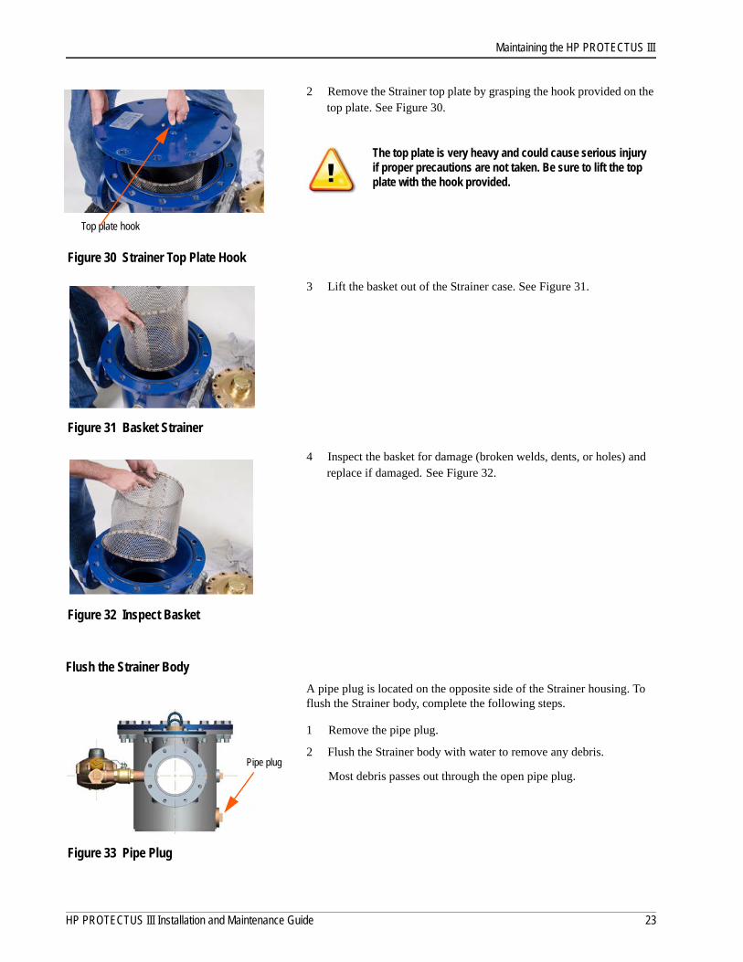
2 Remove the Strainer top plate by grasping the hook provided on the top plate. See Figure 30.
Figure 30 Strainer Top Plate Hook
3 Lift the basket out of the Strainer case. See Figure 31.
Figure 31 Basket Strainer
4 Inspect the basket for damage (broken welds, dents, or holes) and replace if damaged. See Figure 32.
Figure 32 Inspect Basket
Flush the Strainer Body
A pipe plug is located on the opposite side of the Strainer housing. To flush the Strainer body, complete the following steps.
1 Remove the pipe plug.
2 Flush the Strainer body with water to remove any debris.
Most debris passes out through the open pipe plug.
Figure 33 Pipe Plug
The top plate is very heavy and could cause serious injury if proper precautions are not taken. Be sure to lift the top plate with the hook provided.
Top plate hook
Pipe plug
HP PROTECTUS III Installation and Maintenance Guide 23

Maintaining the HP PROTECTUS III
3 Insert the basket into the Strainer case. See Figure 34.
Figure 34 Replace Basket
4 Make sure the O-ring is in the groove on the flange of the Strainer case and is not damaged. See Figure 35.
Figure 35 Strainer Case O-Ring
5 Place the Strainer top plate back on the Strainer case by using the hook provided. See Figure 36.
Figure 36 Strainer Top Plate
6 Line up the bolt holes on the top plate to the bolt holes on the Stainer body.
To prevent the epoxy coat from chipping when installing bolts, place a washer on top of and under the bolt holes.
24 HP PROTECTUS III Installation and Maintenance Guide

Maintaining the HP PROTECTUS III
7 Insert the bolts (with washers) through the top plate into the Strainer case in a crisscross pattern and tighten securely. See Figure 37.
Figure 37 Secure the Strainer Top Plate
Knuckle ValveTo perform maintenance on the knuckle valve, complete the following steps.
1 Remove the bolts from the cover of the knuckle valve. See Figure 38.
Figure 38 Knuckle Valve Top Plate
2 Remove the cover off the knuckle valve housing by using the hook provided. See Figure 39.
Figure 39 Remove Knuckle Valve Top Plate
The knuckle valve is revealed. See Figure 40.
Figure 40 Knuckle Valve
The top plate is very heavy and could cause bodily harm. Lift the top plate with the hook provided.
Washer
Knuckle Valve
HP PROTECTUS III Installation and Maintenance Guide 25
Maintaining the HP PROTECTUS III
Removing the Knuckle Valve
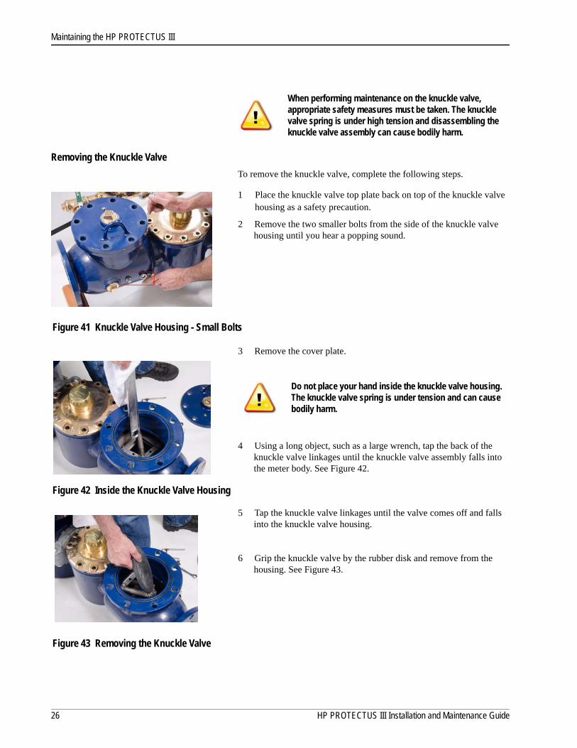
To remove the knuckle valve, complete the following steps.
1 Place the knuckle valve top plate back on top of the knuckle valve housing as a safety precaution.
2 Remove the two smaller bolts from the side of the knuckle valve housing until you hear a popping sound.
Figure 41 Knuckle Valve Housing - Small Bolts
3 Remove the cover plate.
4 Using a long object, such as a large wrench, tap the back of the knuckle valve linkages until the knuckle valve assembly falls into the meter body. See Figure 42.
Figure 42 Inside the Knuckle Valve Housing
5 Tap the knuckle valve linkages until the valve comes off and falls into the knuckle valve housing.
6 Grip the knuckle valve by the rubber disk and remove from the housing. See Figure 43.
Figure 43 Removing the Knuckle Valve
When performing maintenance on the knuckle valve, appropriate safety measures must be taken. The knuckle valve spring is under high tension and disassembling the knuckle valve assembly can cause bodily harm.
Do not place your hand inside the knuckle valve housing. The knuckle valve spring is under tension and can cause bodily harm.
26 HP PROTECTUS III Installation and Maintenance Guide
Maintaining the HP PROTECTUS III
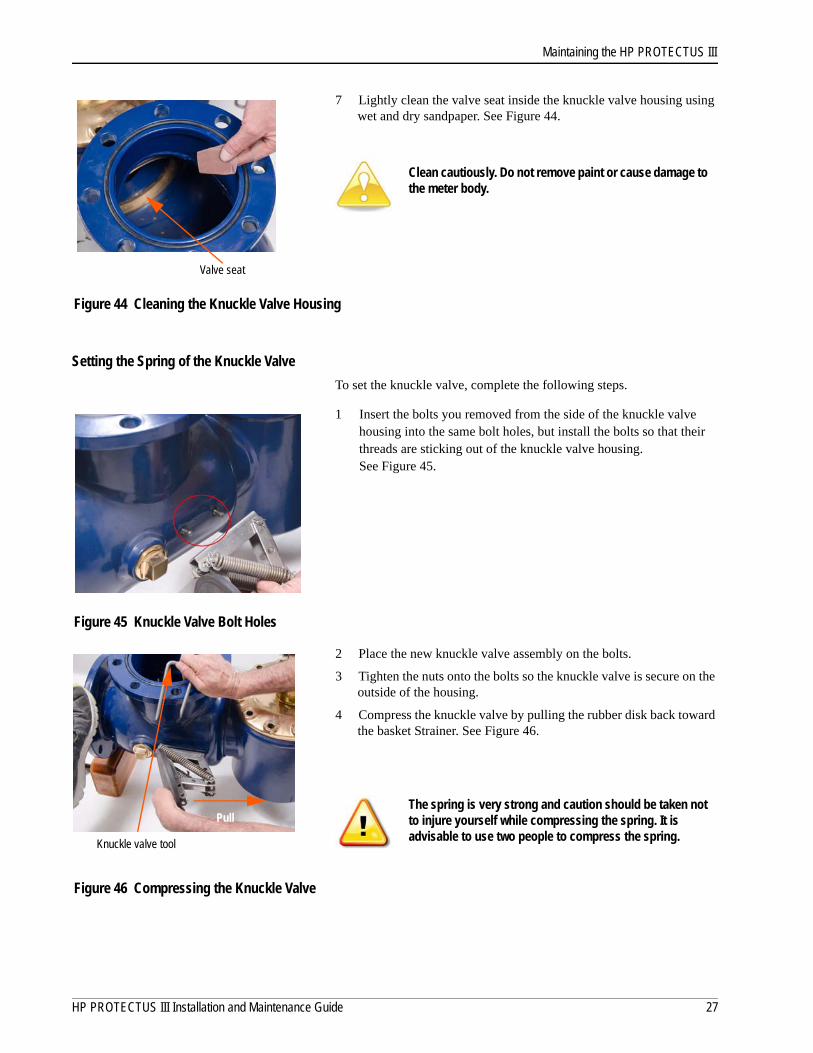
7 Lightly clean the valve seat inside the knuckle valve housing using wet and dry sandpaper. See Figure 44.
Figure 44 Cleaning the Knuckle Valve Housing
Setting the Spring of the Knuckle Valve
To set the knuckle valve, complete the following steps.
1 Insert the bolts you removed from the side of the knuckle valve housing into the same bolt holes, but install the bolts so that their threads are sticking out of the knuckle valve housing.See Figure 45.
Figure 45 Knuckle Valve Bolt Holes
2 Place the new knuckle valve assembly on the bolts.
3 Tighten the nuts onto the bolts so the knuckle valve is secure on the outside of the housing.
4 Compress the knuckle valve by pulling the rubber disk back toward the basket Strainer. See Figure 46.
Figure 46 Compressing the Knuckle Valve
Clean cautiously. Do not remove paint or cause damage to the meter body.
The spring is very strong and caution should be taken not to injure yourself while compressing the spring. It is advisable to use two people to compress the spring.
Valve seat
Knuckle valve tool
Pull
HP PROTECTUS III Installation and Maintenance Guide 27
Maintaining the HP PROTECTUS III
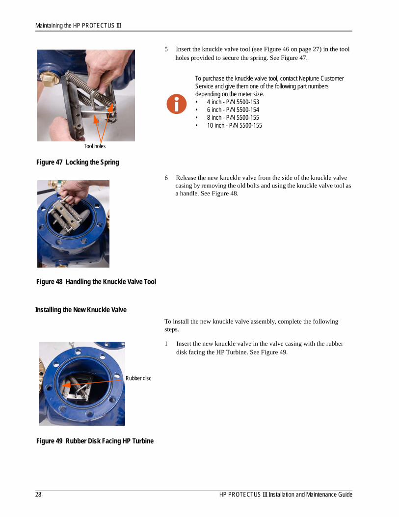
5 Insert the knuckle valve tool (see Figure 46 on page 27) in the tool holes provided to secure the spring. See Figure 47.
Figure 47 Locking the Spring
6 Release the new knuckle valve from the side of the knuckle valve casing by removing the old bolts and using the knuckle valve tool as a handle. See Figure 48.
Figure 48 Handling the Knuckle Valve Tool
Installing the New Knuckle Valve
To install the new knuckle valve assembly, complete the following steps.
1 Insert the new knuckle valve in the valve casing with the rubber disk facing the HP Turbine. See Figure 49.
Figure 49 Rubber Disk Facing HP Turbine
To purchase the knuckle valve tool, contact Neptune Customer Service and give them one of the following part numbers depending on the meter size.• 4 inch - P/N 5500-153• 6 inch - P/N 5500-154• 8 inch - P/N 5500-155• 10 inch - P/N 5500-155
Tool holes
Rubber disc
28 HP PROTECTUS III Installation and Maintenance Guide

Maintaining the HP PROTECTUS III
2 Reinstall the bolts holding the knuckle valve so that the threads are now going into the knuckle valve housing. If the old bolts are undamaged, reuse them. See Figure 50.
3 Tighten bolts until the valve is secure.
Figure 50 Inserting New Bolts
4 Insert a long object like a crowbar into the knuckle valve casing and hook the knuckle valve tool. See Figure 51.
5 Lift the knuckle valve tool up and away from the knuckle valve.
6 Make sure the bolts, washers, and nuts are secure.
Figure 51 Remove Knuckle Valve Tool
7 Make sure the O-ring is not damaged and is set in the grooves in the flange on top of the knuckle valve casing. See Figure 52.
Figure 52 Knuckle Valve O-ring
8 Place the top plate on the knuckle valve casing.
Do not place your hand inside the knuckle valve housing. The knuckle valve spring is under tension and can cause bodily harm.
Knuckle valve tool
O-ring
HP PROTECTUS III Installation and Maintenance Guide 29
Maintaining the HP PROTECTUS III
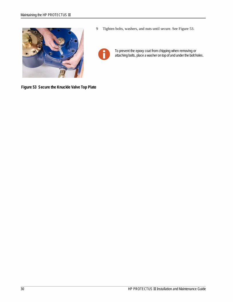
9 Tighten bolts, washers, and nuts until secure. See Figure 53.
Figure 53 Secure the Knuckle Valve Top Plate
To prevent the epoxy coat from chipping when removing or attaching bolts, place a washer on top of and under the bolt holes.
30 HP PROTECTUS III Installation and Maintenance Guide
5 Contacting Neptune Customer Support
Within North America, Neptune Customer Support is available Monday through Friday, 7:00 AM to 5:00 PM Central Standard Time by telephone, email, or fax.
By PhoneTo contact Neptune Customer Support by phone, complete the following steps.
1 Call (800) 647-4832.
2 Select one of the following options.
• Press 1 if you have a Technical Support Personal Identification Number (PIN).
• Press 2 if you do not have a Technical Support PIN number.
3 Enter the six digit PIN number and press #.
4 Select one of the following options.
• Press 2 for Technical Support.
• Press 3 for maintenance contracts or renewals.
• Press 4 for Return Material Authorization (RMA) for Canadian Accounts.
You are directed to the appropriate team of Customer Support Specialists. The specialists are dedicated to you until the issue is resolved to your satisfaction. When you call, be prepared to give the following information.
• Your name and utility or company name.
• A description of what occurred and what you were doing at the time.
• A description of any actions taken to correct the issue.
By FaxTo contact Neptune Customer Support by fax, send a description of your problem to (334) 283-7497. Please include on the fax cover sheet the best time of day for a customer support specialist to contact you.
By EmailTo contact Neptune Customer Support by email, send your message to [email protected].
HP PROTECTUS III Installation and Maintenance Guide 31

Contacting Neptune Customer Support
Notes:
32 HP PROTECTUS III Installation and Maintenance Guide
Appendix A: Detaching the Basket Strainer
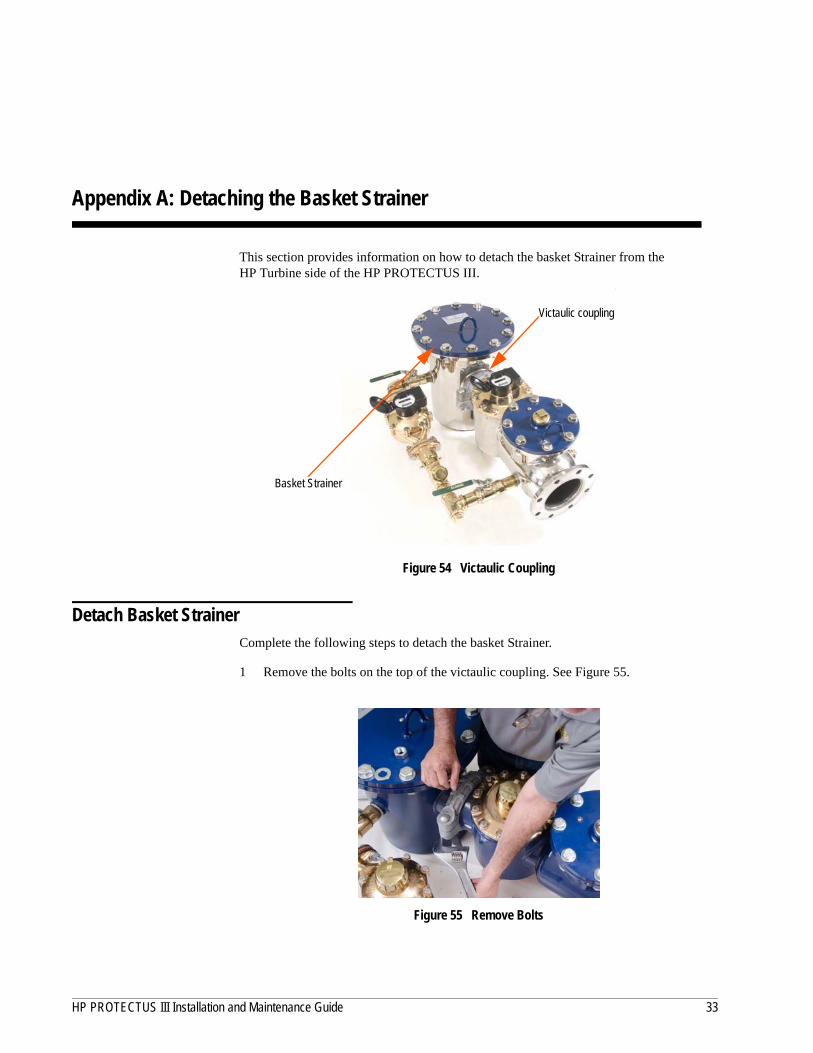
This section provides information on how to detach the basket Strainer from the HP Turbine side of the HP PROTECTUS III.
Figure 54 Victaulic Coupling
Detach Basket StrainerComplete the following steps to detach the basket Strainer.
1 Remove the bolts on the top of the victaulic coupling. See Figure 55.
Figure 55 Remove Bolts
Victaulic coupling
Basket Strainer
HP PROTECTUS III Installation and Maintenance Guide 33
Appendix A
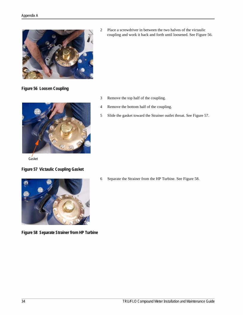
2 Place a screwdriver in between the two halves of the victaulic coupling and work it back and forth until loosened. See Figure 56.
Figure 56 Loosen Coupling
3 Remove the top half of the coupling.
4 Remove the bottom half of the coupling.
5 Slide the gasket toward the Strainer outlet throat. See Figure 57.
Figure 57 Victaulic Coupling Gasket
6 Separate the Strainer from the HP Turbine. See Figure 58.
Figure 58 Separate Strainer from HP Turbine
Gasket
34 TRU/FLO Compound Meter Installation and Maintenance Guide
Appendix A
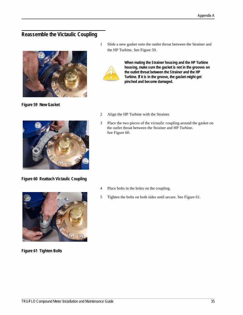
Reassemble the Victaulic Coupling
1 Slide a new gasket onto the outlet throat between the Strainer and
the HP Turbine. See Figure 59.
Figure 59 New Gasket
2 Align the HP Turbine with the Strainer.
3 Place the two pieces of the victaulic coupling around the gasket on the outlet throat between the Strainer and HP Turbine. See Figure 60.
Figure 60 Reattach Victaulic Coupling
4 Place bolts in the holes on the coupling.
5 Tighten the bolts on both sides until secure. See Figure 61.
Figure 61 Tighten Bolts
When mating the Strainer housing and the HP Turbine housing, make sure the gasket is not in the grooves on the outlet throat between the Strainer and the HP Turbine. If it is in the groove, the gasket might get pinched and become damaged.
TRU/FLO Compound Meter Installation and Maintenance Guide 35

Appendix A
Notes:
36 HP PROTECTUS III Installation and Maintenance Guide

Appendix B: HP PROTECTUS III Parts List
This appendix describes the individual parts that makeup the HP PROTECTUS III meter.
HP PROTECTUS IIIThe following diagrams are a representative breakdown of the HP PROTECTUS III. Table 8 on page 38 describes each part of the diagram.
Figure 62 Representative Breakdown of the HP PROTECTUS III
HP PROTECTUS III Installation and Maintenance Guide 37
Appendix B
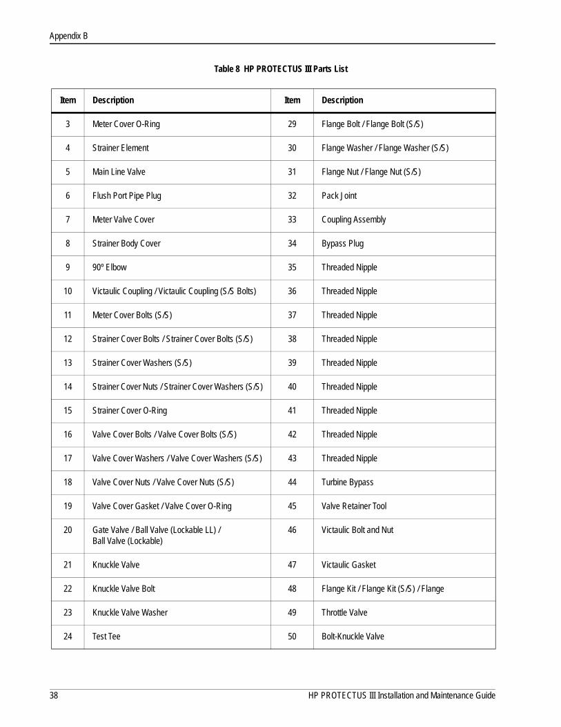
Table 8 HP PROTECTUS III Parts List
Item Description Item Description
3 Meter Cover O-Ring 29 Flange Bolt / Flange Bolt (S/S)
4 Strainer Element 30 Flange Washer / Flange Washer (S/S)
5 Main Line Valve 31 Flange Nut / Flange Nut (S/S)
6 Flush Port Pipe Plug 32 Pack Joint
7 Meter Valve Cover 33 Coupling Assembly
8 Strainer Body Cover 34 Bypass Plug
9 90º Elbow 35 Threaded Nipple
10 Victaulic Coupling / Victaulic Coupling (S/S Bolts) 36 Threaded Nipple
11 Meter Cover Bolts (S/S) 37 Threaded Nipple
12 Strainer Cover Bolts / Strainer Cover Bolts (S/S) 38 Threaded Nipple
13 Strainer Cover Washers (S/S) 39 Threaded Nipple
14 Strainer Cover Nuts / Strainer Cover Washers (S/S) 40 Threaded Nipple
15 Strainer Cover O-Ring 41 Threaded Nipple
16 Valve Cover Bolts / Valve Cover Bolts (S/S) 42 Threaded Nipple
17 Valve Cover Washers / Valve Cover Washers (S/S) 43 Threaded Nipple
18 Valve Cover Nuts / Valve Cover Nuts (S/S) 44 Turbine Bypass
19 Valve Cover Gasket / Valve Cover O-Ring 45 Valve Retainer Tool
20 Gate Valve / Ball Valve (Lockable LL) / Ball Valve (Lockable)
46 Victaulic Bolt and Nut
21 Knuckle Valve 47 Victaulic Gasket
22 Knuckle Valve Bolt 48 Flange Kit / Flange Kit (S/S) / Flange
23 Knuckle Valve Washer 49 Throttle Valve
24 Test Tee 50 Bolt-Knuckle Valve
38 HP PROTECTUS III Installation and Maintenance Guide
Appendix B
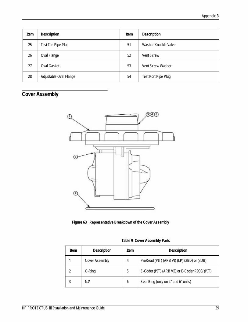
Cover Assembly
Figure 63 Representative Breakdown of the Cover Assembly
25 Test Tee Pipe Plug 51 Washer-Knuckle Valve
26 Oval Flange 52 Vent Screw
27 Oval Gasket 53 Vent Screw Washer
28 Adjustable Oval Flange 54 Test Port Pipe Plug
Item Description Item Description
Table 9 Cover Assembly Parts
Item Description Item Description
1 Cover Assembly 4 ProRead (PIT) (ARB VI) (LP) (2BD) or (3DB)
2 O-Ring 5 E-Coder (PIT) (ARB VII) or E-Coder R900i (PIT)
3 N/A 6 Seal Ring (only on 4” and 6” units)
HP PROTECTUS III Installation and Maintenance Guide 39

Appendix B
Notes:
40 HP PROTECTUS III Installation and Maintenance Guide

Glossary
AWWA American Water Works Association
bleed screw Valve used for allowing accumulations of gas in a liquid to blow off.
bypass meter Positive displacement, mutating disc type. It can be piped on the left or right side of the assembly.
bypass valve Valve placed to control the flow of liquid through a bypass.
flange Ring or collar, usually provided with holes for bolts.
FM Factory Manual
gasket Piece of rubber or some other material that is used to make a tight seal between two parts that are joined together.
HP High Performance
knuckle valve Rubber faced disc that is held closed with the springs or linkages visible.
leakage Accidental admission or escape of a fluid through a hole or crack.
registration Volume of water that went through the meter. Per seep hand revolution.
spring Resilient device, typically a helical metal coil, that can be pressed or pulled but returns to its former shape.
Strainer Strainer protecting the meter from debris in the line and corrects the velocity profile of the flow to the meter.
throttle valve Valve used to regulate the amount of flow that is passing through the T-10.
UL Underwriters Laboratory
UME Unitized Measuring Element
HP PROTECTUS III Installation and Maintenance Guide 41

Glossary
Victaulic® coupling A development in which a groove is cut around each end of pipe instead of the usual threads. Two ends of pipe are then lined up and a rubber ring is fitted around the joint. Two semicircular bands, forming a sleeve, are placed around the ring and are drawn together with two bolts, which have a ridge on both edges to fit into the groove of the pipe. As the bolts are tightened, the rubber ring is compressed, making a watertight joint, while the ridges fitting in the grooves make it strong mechanically.
42 HP PROTECTUS III Installation and Maintenance Guide

Index
A
accurately 10application 5AWWA 1, 4
B
back pressure 11basement 11basket 3, 10
stainless steel 3strainer 11, 22
bleed screw 12, 13, 15bypass, bronze 3
C
calibration vane 12characteristics, operating 5cover, HP turbine 21criss-cross 20
D
damage 9debris 3, 10, 17diagrams 6dial 8dimensions 6disc chamber 17, 18, 19disc strainer 19downstream ball valve 13, 15
E
epoxy coat 3
F
fire service 10flange 24flow rate 3flow rate, maximum intermittent 5
H
hook 23horizontal 11HP turbine 3, 16, 21
I
inlet side gate valve 12, 15inspect 9installation 9, 10
preliminary checks 10safety 10
K
knuckle valve 2, 3, 11, 14, 15, 25knuckle valve top plate 26
L
leaking 3lifting hook 10lock nut 12lockable ball valves 3low flow 5
M
mainline 11maximum operating pressure 5measuring element 2measuring element, turbine 3meters
construction 3operation 3
N
normal operating range 5
O
odometer 8operating, characteristics 5o-ring 2, 3, 24outlet 2outlet side gate valve 13, 15
P
pipe 10pit 11position, normal operating 10pressure loss 3push button, throttle valve 18

Index
R
range, normal operating 5register 3, 12registration 6regulate 2replacement 2return of damaged unit 9rotor 2
S
sandpaper 20seal pin 12specifications
environmental 5operating characteristic 5
square o-ring 19storage 9strainer 2, 3, 14
basket 11, 22case. 23cleaning 10disc 19installing 10top plate 22
sweep hand 8
T
T-10bypass 2, 3, 14disc chamber 19gasket 17top plate 16, 20
tension 26test port 11throttle valve 2, 14, 18
tools and materials 9top plate 20
knuckle valve 26strainer 22T-10 16
transitioning 3turbine measuring element 10, 14turbine, rotor 2
U
UME 4, 12, 15, 22design 15precalibrated 15replacing 16
unpacking 9upstream ball valve 13, 15
V
valvedownsteam ball 15downstream ball 13inlet side gate 12, 15knuckle 2, 3, 14, 15, 25lockable ball 3outlet side gate 13, 15throttle 2, 14, 18upstream ball 15upstream ball valve 13
variation 11vault 10
W
warranty 4work order 10
44 HP PROTECTUS III Installation and Maintenance Guide


neptunetg.com
TAKE CONTROL
IM HP PROTECTUS III 11.15 Part No. 13505-021 © Copyright 2015, Neptune Technology Group Inc. Neptune is a registered trademark of Neptune Technology Group Inc.
Neptune Technology Group Inc.1600 Alabama Highway 229Tallassee, AL 36078USATel: (800) 633-8754Fax: (334) 283-7293
Neptune Technology Group (Canada) Ltd.7275 West Credit AvenueMississauga, OntarioL5N 5M9CanadaTel: (905) 858-4211Fax: (905) 858-0428
Neptune Technology Group Inc.Avenida Ejército Nacional No. 418Piso 12, Despacho 1203Colonia Polanco V Sección. C.P. 11560Delegación Miguel HidalgoMéxico, Distrito FederalTel: +(525) 5203 5294 / +(525) 5203 4032Fax: +(525) 5203 6503