i.lon smartserver hardware guide - echelon...
TRANSCRIPT

i.LON® SmartServer Hardware Guide
0 7 8 - 0 3 4 6 - 0 1 C
®

ii
Echelon, i.LON, LON, LONORKS, LonTalk, Neuron, LONMARK, 3120, 3150, LNS, LonMaker, and the Echelon logo are trademarks of Echelon Corporation registered in the United States and other countries. LonPoint and LonSupport are trademarks of Echelon Corporation.
Other brand and product names are trademarks or registered trademarks of their respective holders.
Neuron Chips, LonPoint Modules, and other OEM Products were not designed for use in equipment or systems which involve danger to human health or safety or a risk of property damage and Echelon assumes no responsibility or liability for use of the Neuron Chips or LonPoint Modules in such applications.
Parts manufactured by vendors other than Echelon and referenced in this document have been described for illustrative purposes only, and may not have been tested by Echelon. It is the responsibility of the customer to determine the suitability of these parts for each application.
ECHELONMAKES NO REPRESENTATION, WARRANTY, OR CONDITION OF ANY KIND, EXPRESS, IMPLIED, STATUTORY, OR OTHERWISE OR IN ANY COMMUNICATION WITH YOU, INCLUDING, BUT NOT LIMITED TO, ANY IMPLIED WARRANTIES OF MERCHANTABILITY, SATISFACTORY QUALITY, FITNESS FOR ANY PARTICULAR PURPOSE, NONINFRINGEMENT, AND THEIR EQUIVALENTS.
No part of this publication may be reproduced, stored in a retrieval system, or transmitted, in any form or by any means, electronic, mechanical, photocopying, recording, or otherwise, without the prior written permission of Echelon Corporation.
Printed in the United States of America. Copyright ©1997–2008 by Echelon Corporation. Echelon Corporation www.echelon.com

i.LON SmartServer Hardware Guide iii
Preface
The i.LON® SmartServer is a low-cost, high-performance controller, network manager, router, remote network interface, and Web server that you can use to
connect LONWORKS®, Modbus, and M-Bus devices to corporate IP networks or the Internet.

iv Preface
FCC Compliance Statement – Class B This equipment has been tested and found to comply with the limits for a Class B digital device pursuant to Part 15 of the FCC Rules. These limits are designed to provide reasonable protection against harmful interference in a residential installation. This equipment generates, uses, and can radiate radio frequency energy and, if not installed and used in accordance with the manufacturer’s instruction manual, may cause interference with radio communications. However, there is no guarantee that interference will not occur in a particular installation. If this equipment does cause harmful interference to radio or television reception, which can be determined by turning the equipment off and on, you are encouraged to try to correct the interference by one or more of the following measures:
• Reorient or relocate the receiving antenna.
• Increase the separation between the equipment and the receiver.
• Connect the equipment into an outlet on a circuit different from that which the receiver is connected.
• Consult the dealer or an experienced radio/television technician for help.
• Changes or modifications not expressly approved by the party responsible for compliance could void the user’s authority to operate the equipment.
IC Compliance Statement – Class B This Class B digital apparatus meets the requirements of the Canadian Interference-Causing Equipment Regulations of ICES-003.
VCCI Compliance Statement – Class B ITE
This is a Class B product based on the standard of the Voluntary Control Council for Interference (VCCI) for information technology equipment. If this equipment is used near a radio or television receiver in a domestic environment, it may cause radio interference. Install and use the equipment according to the instruction manual.

i.LON SmartServer Hardware Guide v
Welcome The SmartServer is a low-cost, high-performance controller, network manager, router, remote network interface, and Web server that you can use to connect LONWORKS , Modbus, and M-Bus devices to corporate IP networks or the Internet.
You can connect the SmartServer to a LONWORKS TP/FT-10 channel using the LonTalk connections on the hardware and a high-voltage 100/240V AC mains connection. You can connect the SmartServer to a PL-20 LONWORKS channel through the high-voltage 100/240V AC mains connection. You can also connect a special PL-20 model of the SmartServer that has an external coupling circuit to a single-phase or three-phase external coupler.
The SmartServer hardware includes a RS-232 port for connecting external GSM modems, M-Bus and Modbus devices, and other device types, and a RS-485 port for connecting Modbus devices and other device types. In addition, the SmartServer has two digital inputs, two digital outputs, and two pulse meter inputs for connecting electric, gas, and water meters.
Once you have wired all the connections for the SmartServer, you can connect the SmartServer to TCP/IP networks using its RJ-45 10/100 BaseT Ethernet port. You can also connect models of the SmartServer that have built-in 56K V.90 analog modems to TCP/IP networks using their RJ-11 telephone line ports and a dial-out connection.
Optionally, you can connect the RS-232 console port on the SmartServer to a computer running a terminal emulation program such as Windows HyperTerminal. This enables you to configure the SmartServer using its console application. Note that you should configure the SmartServer with its built-in Web pages whenever possible.
Purpose This document describes how to assemble, mount, and wire the SmartServer hardware. It also describes the service buttons and LEDs on the SmartServer hardware.
Audience This guide is intended for Echelon’s customers, OEMs, system designers, and integrators with an understanding of control networks.
Models There are 13 models of the SmartServer available for use on TP/FT-10 free topology and PL-20 power line channels. This includes the following:
• Eight high-voltage TP/FT-10 models that include none to all of the following options: IP-852 routing, programming, and modem.
• Four PL-20 models that include none to all of the following options: IP-852 routing and programming.
• One PL-20 model that includes an external coupling circuit. The external coupling circuit enables the PL-20 model to communicate over virtually any AC or DC power mains.

vi Preface
The following table lists the SmartServer model numbers, the features included with the model, and the power supply used:
Options
IP-852
Routing Programming Modem
72101R-400 (FT)
72101R-408 (FT) x
72101R-409 (FT) x
72101R-410 (FT) x x
72102R-400 (FT) x
72102R-408 (FT) x x
72102R-409 (FT) x x
72102R-410 (FT) x x x
72103R-400 (PL)
72103R-408 (PL) x
72103R-409 (PL) x
72103R-410 (PL) x x
72103R-420 (PL) External coupling
Note: You can order programming and IP-852 routing licenses for units that do not have these options pre-installed.
Box Contents The i.LON SmartServer hardware ships with the following material:
• i.LON SmartServer DVD. This DVD contains the Echelon i.LON SmartServer software, Echelon i.LON Programming Tools Demo, Echelon i.LON Enterprise Services, Adobe® Contribute® CS3 Trial Edition, Echelon i.LON Vision software, Microsoft Internet Explorer 7, and Adobe Acrobat® Reader 8.1.1.
In addition, this DVD contains the installation software for the following support products that are required to run the i.LON SmartServer software: LNS 3 Service Pack 8, Update 2; LonMaker 3.1 Service Pack 3, Update 2, which updates the LNS runtime used by the LonMaker Integration Tool to the LNS Turbo Edition version; NodeBuilder Resource Editor 3.14, and OpenLDV 3.4.
This DVD also includes Adobe Acrobat PDF files for all the i.LON SmartServer documentation
• i.LON SmartServer Quick Start Guide. This document describes how to install the i.LON SmartServer software, connect the SmartServer hardware, set the SmartServer IP address, and select a network management service to run the network attached to your SmartServer.
New Hardware Features The hardware for the SmartServer version of the i.LON has been significantly enhanced. The most notable improvements are in the unit’s memory. Specifically, the SDRAM has been increased from 32 to 64MB, the NAND flash memory has been increased from 32 to 64MB, and the EEPROM has been increased from 512 to 2,048 bytes. These improvements support the new standalone and LNS network

i.LON SmartServer Hardware Guide vii
management features of the SmartServer software. Overall, the SmartServer version of the i.LON hardware includes the following new features and improvements:
• 64 MB SDRAM • 64 MB NAND flash memory • 2,048 bytes EEPROM • 2MB bootROM • Extended temperature (-40 to 60°C) for PL model components. • External coupling option available for PL model (Model 72103R-420) • Carrier detect line for external modems. • Reset line to internal modem • Improved surge performance • Improved RF immunity
i.LON SmartServer Documentation The documentation for the i.LON SmartServer is provided as Adobe Acrobat PDF files and online help files. The PDF files for all the SmartServer documents except for i.LON SmartServer Freely Programmable Module (FPM) Developer’s Guide are installed in the Echelon i.LON SmartServer program folder when you install the i.LON SmartServer software. The PDF file for the i.LON SmartServer Programming Tools User’s Guide is installed in the Echelon i.LON FPM Development folder when you install the i.LON SmartServer Programming Tools software. You can also find and download the latest i.LON SmartServer documentation, including the current version of this guide, from Echelon’s Web site at www.echelon.com/support/documentation/manuals/cis.
This hardware guide and the following documents comprise the SmartServer documentation suite:
• i.LON SmartServer User’s Guide. Describes how to configure the SmartServer and use its applications to manage control networks.
• i.LON SmartServer Power Line Repeating Network Management Guide. Describes how to install a PL-20 repeating network and how to use the i.LON to prepare, maintain, monitor and control, and connect the network.
• i.LON SmartServer Programming Tools User’s Guide. Describes how to create custom embedded applications and drivers, which are referred to as Freely Programmable Modules (FPMs), and deploy them on your SmartServer. FPMs let you implement custom functionality and tailor the SmartServer to meet your needs.
• i.LON SmartServer Programmer’s Reference. Describes how to configure the SmartServer using XML files and SOAP calls.
• IP-852 Channel User’s Guide. Describes how to configure an IP-852 channel with the Echelon LONWORKS/IP Configuration Server. You will need this information if you plan to use the SmartServer as an IP-852 router.
Related Reading The following additional documents may be useful if you are using certain features of the i.LON. You can download these documents from Echelon’s Web site at www.echelon.com.
• LonMaker® User’s Guide. Describes how to use the LonMaker tool, which you can use to install the SmartServer in a LONWORKS network.
• LNS® Programmer’s Guide. Describes how to write LNS applications that take advantage of the network design, installation, maintenance, and control/monitoring capabilities provided by the SmartServer.
• OpenLDV™ Programmer’s Guide, xDriver Supplement. Describes how an LNS or OpenLDV application can use the xDriver software to manage communications with multiple LONWORKS
viii Preface
networks over a TCP/IP network. The xDriver software is used to communicate with the SmartServer when it is functioning as a Remote Network Interface (RNI).
• NodeBuilder User’s Guide. Describes how to use the NodeBuilder tool to develop and test the applications for Neuron-hosted devices.
Content This guide includes the following content:
• Assembling the SmartServer Hardware. Describes how to mount the SmartServer hardware inside a suitable enclosure. Describes how to connect the SmartServer hardware to power supplies; LONWORKS FT-10 and PL-20 channels; digital input, digital output, and pulse meter input devices; and TCP/IP networks. Describes how to connect the SmartServer console port to access its console application.
• Using the SmartServer Service Buttons and LEDs. Describes how to use the service buttons and LEDs on the SmartServer hardware.
For More Information and Technical Support The i.LON SmartServer ReadMe provides descriptions of known problems and their workarounds. To view the i.LON SmartServer ReadMe, click Start, point to Programs, point to Echelon i.LON SmartServer Software, and then select i.LON SmartServer ReadMe First. You can also find additional information about the i.LON SmartServer online at www.echelon.com/products/cis/.
If you have technical questions that are not answered by the SmartServer documentation, SmartServer online help, or i.LON Web page, you can get technical support from Echelon. Your SmartServer distributor may also provide customer support. You can also enroll in training classes at Echelon or an Echelon training center to learn more about how to use the SmartServer.
To receive technical support from Echelon for the SmartServer, you must purchase support services from Echelon or an Echelon support partner. See www.echelon.com/support for more information on Echelon support and training services. There is no charge for software installation-related questions during the first 30 days after you receive the i.LON SmartServer DVD.
You can obtain technical support via phone, fax, or e-mail from your closest Echelon support center. The contact information is as follows:
Region Languages Supported Contact Information The Americas
English Japanese
Echelon Corporation Attn. Customer Support 550 Meridian Avenue San Jose, CA 95126 Phone (toll-free): 800 258 4LON(258-4566) Phone: 408 938 5200 Fax: 408 790 3801 [email protected]
Europe
English German French Italian
Echelon UK 16, The Courtyards Hatters Lane Watford Herts. WD18 8YH United Kingdom Phone: 44 0 1923 430200 Fax: 44 0 1923 430300
i.LON SmartServer Hardware Guide ix
Power Line Repeating Beta Note: European support for the Power Line Repeating Network Management Beta is being provided by the following:
Echelon EDC Herbert-Hinnendahl-Str 23 33602 Bielefeld Germany Main Phone: (49) 521-967 40 82Main Fax: (49) 521-967 40 83
Japan
Japanese Echelon Japan Holland Hills Mori Tower, 18F 5-11-2 Toranomon, Minato-ku Tokyo 105-0001 Japan Phone: 81 3 5733 3320 Fax: 81 3 5733 3321 [email protected]
China
Chinese English
Echelon Greater China Rm. 1007-1008, IBM Tower Pacific Century Place 2A Gong Ti Bei Lu Chaoyang District Beijing 100027, China Phone: 86 10 6539 3750 Fax: 86 106539 3754 [email protected]
Other Regions
English Phone: 408 938 5200 Fax: 408 328 3801 [email protected]
You can submit a feedback form with suggestions on how to improve the product’s functionality and documentation at www.echelon.com/company/feedback. This feedback form is not forwarded to technical support and should not be used to submit technical or product support related issues—send technical support questions to your Echelon support center.

x Preface
Table of Contents Preface .................................................................................................... iii
FCC Compliance Statement – Class B .......................................................... iv IC Compliance Statement – Class B........................................................ iv VCCI Compliance Statement – Class B ITE............................................ iv
Welcome.......................................................................................................... v Purpose ........................................................................................................... v Audience.......................................................................................................... v Models ............................................................................................................. v Box Contents .................................................................................................. vi New Hardware Features................................................................................. vi i.LON SmartServer Documentation................................................................vii Related Reading.............................................................................................vii Content ..........................................................................................................viii For More Information and Technical Support................................................viii Table of Contents ............................................................................................ x
1 Assembling the SmartServer Hardware.......................................... 1 Assembly Overview ......................................................................................... 2 Mounting the SmartServer............................................................................... 3 Wiring the SmartServer Connections .............................................................. 5
Connecting the Screw Terminals .............................................................. 6 Power Supply ..................................................................................... 6 LONWORKS Network............................................................................ 9 RS-232/RS-485 Serial Ports............................................................. 10 Digital Outputs .................................................................................. 13 Pulse Meter Inputs............................................................................ 14 Digital Inputs..................................................................................... 16 +12V < 20mA Output........................................................................ 17
Connecting the Ethernet Port ........................................................................18 Connecting the Console Port......................................................................... 18 Connecting the Telephone Line Port............................................................. 19 Applying Power to the SmartServer .............................................................. 19
2 Using the SmartServer LEDs and Service Buttons...................... 21 Using the SmartServer LEDs ........................................................................22 Using the SmartServer Service Buttons........................................................ 23
i.LON SmartServer Hardware Guide 1
1
Assembling the SmartServer Hardware
This chapter describes how to mount the SmartServer hardware inside a suitable enclosure. It describes how to connect the SmartServer hardware to a power supply;
LONWORKS FT-10 and PL-20 channels; digital input, digital output, and pulse meter input devices; and TCP/IP networks. It describes how to connect the SmartServer
console port to access its console application.

2 Assembling the SmartServer Hardware
Assembly Overview You need to assemble the SmartServer and connect it to a TCP/IP network before you can configure it and begin using its embedded applications. This section lists the general steps required to assemble and connect the SmartServer. These steps are then detailed in the referenced sections.
1. Mount the SmartServer inside a suitable enclosure. For more information on this step, see the next section, Mounting the SmartServer.
2. Connect the screw terminals on the SmartServer.
a. You must connect the power screw terminals for all SmartServer models as described in the Power Supply section in this chapter.
b. If you are assembling an FT-10 model of the SmartServer, you must connect a LONWORKS FT-10 channel to the LON A®/PLT + and LON B®/PLT - screw terminals on the hardware (screw terminals 18 and 17). For more information, see LONWORKS Network in this chapter.
If you are assembling the PL-20 model of the SmartServer with the external coupling option (Model 72103R-420), you can connect twisted pair wiring between screw terminals 17 and 18 and a single-phase or three-phase external coupler. For more information, see LONWORKS Network in this chapter. All other PL-20 models of the SmartServer communicate through the power supply and therefore do not require any additional connections.
c. Optionally, you can connect the screw terminals for the RS-232/RS-485 serial ports, digital outputs, pulse meter inputs, digital inputs, and +12V <20mA output on the hardware as described in the respective sections in this chapter for each of these connections.
3. Connect the Ethernet port on the SmartServer. Connect one end of an Ethernet cable to the Ethernet port on the SmartServer, and then connect the other end to an Ethernet hub or switch that can communicate with your computer (TCP/IP network). The Ethernet port on the SmartServer is auto-switching; therefore, you can use a straight-through or crossover Ethernet cable. For more information on this step, see Connecting the Ethernet Port in this chapter.
4. Optionally, you can connect the console port on the SmartServer. Connect one end of a RS-232 null modem cable to the console port on the SmartServer, and then connect the other end to one of the COM ports on your computer. You can then use a terminal emulation program such as Windows HyperTerminal on your computer to access the SmartServer’s console application and configure the SmartServer. The default communication properties for the SmartServer are 9600- 8-None-1-None. Note that you should use the SmartServer’s built-in Web pages to configure the SmartServer whenever possible. For more information on this step, see Connecting the Console Port in this chapter.
5. If you are assembling a SmartServer that has a built-in analog modem, connect the telephone port on the SmartServer. For more information on this step, see Connecting the Telephone Line Port in this chapter.
6. Apply power to the SmartServer. For more information on this step, see Applying Power to the SmartServer in this chapter.
7. Connect your SmartServer to a TCP/IP network.
a. If your computer is not on the subnet as your SmartServer, open a command prompt and type the following command (change “192.168.1.0” to the appropriate prefix for your subnet):
route add 192.168.1.0 mask 255.255.255.0 %computername%
Note: If you are running Windows Vista™ on your computer, you need to open the command prompt with administrator privileges. To do this, click Start, type cmd in the search box, right-click the cmd.exe, and then select Run as Administrator. If you receive a “The parameter is incorrect” error after entering the route command, replace %computername% with the IP address of your computer.
i.LON SmartServer Hardware Guide 3
b. Open Internet Explorer 6 or later and enter the following URL: 192.168.1.222. Your SmartServer home page opens.
c. Click the Login button. A login dialog appears. Enter ilon for both the User Name and the Password and then click OK. The i.LON SmartServer – Welcome Web page opens.
d. You can configure your SmartServer and begin using its embedded applications as described in the i.LON SmartServer User’s Guide.
Mounting the SmartServer
!
Caution The SmartServer is intended to be mounted inside a suitable, safety-agency approved enclosure that is mounted in a restricted access area. High-voltage wiring must be performed only by a qualified service person.
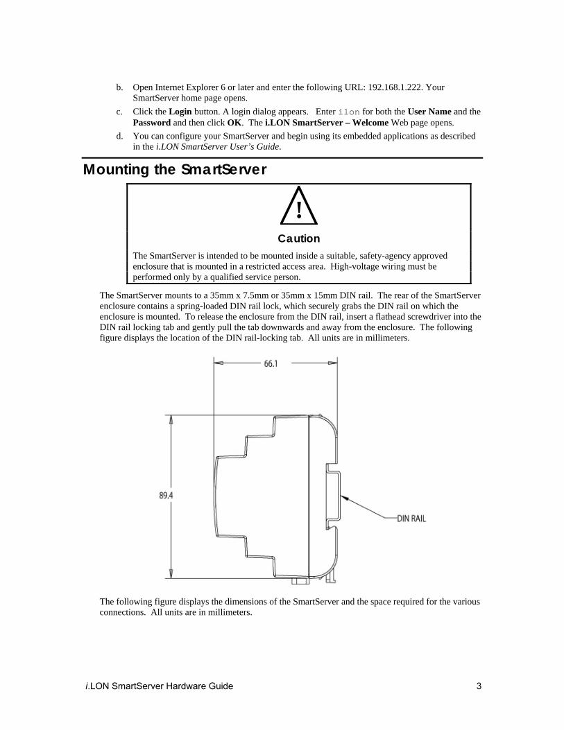
The SmartServer mounts to a 35mm x 7.5mm or 35mm x 15mm DIN rail. The rear of the SmartServer enclosure contains a spring-loaded DIN rail lock, which securely grabs the DIN rail on which the enclosure is mounted. To release the enclosure from the DIN rail, insert a flathead screwdriver into the DIN rail locking tab and gently pull the tab downwards and away from the enclosure. The following figure displays the location of the DIN rail-locking tab. All units are in millimeters.
The following figure displays the dimensions of the SmartServer and the space required for the various connections. All units are in millimeters.

4 Assembling the SmartServer Hardware

i.LON SmartServer Hardware Guide 5
Wiring the SmartServer Connections After you mount the SmartServer, you can wire its connections. The SmartServer has two rows of screw terminals, an RJ-45 10/100 Base T Ethernet port, a DB-9 console port, and an RJ-11 telephone line (SmartServer models 72102).
You must connect the power screw terminals for all SmartServer models as described in the Power Supply section. If you are assembling an FT-10 model of the SmartServer, you must connect a LONWORKS TP/FT-10 channel to the LON A® and LON B® screw terminals (18 and 17). Optionally, you can connect the other screw terminals on the SmartServer (the RS-232/RS-485 serial ports, digital outputs, pulse meter inputs, digital inputs, and the +12V <20mA output).
After you connect the screw terminals, you should use an Ethernet cable to connect the Ethernet port on the SmartServer to a TCP/IP network. This enables you to configure the SmartServer using its built-in Web pages and begin using its embedded applications. Optionally, you can connect the console port on the SmartServer so that you can use the SmartServer console application to configure the SmartServer. However, you should configure the SmartServer with the Web pages whenever possible.
If you are assembling the model 72102 of the SmartServer and you need a dial-out connection to connect the SmartServer to a TCP/IP network, you should wire the RJ-11 telephone port on the SmartServer.
The following figure illustrates the location of all the SmartServer connections.

6 Assembling the SmartServer Hardware
Connecting the Screw Terminals The SmartServer has two rows of screw terminals located on the top and bottom edges of the enclosure. The screw terminals on the bottom row are numbered 1 to 12 (from left to right), and the screw terminals on the top row are numbered 13 to 28 (from right to left). No that there is no polarity for DC connections.
The screw terminals accept 0.22mm – 3.3mm (22 – 12AWG) gauge solid wire. The optimum tightening torque for the screw terminals is 0.75 Newton-meters (6 lbs. in.) maximum. The ideal flathead screwdriver tip width for use with the screw terminal connectors is 3mm (0.12”). Wires should be stripped to a length of 7mm (0.28”). Optionally, you can use a soldering iron to tin the stripped lengths of any stranded wires to prevent fraying and inadvertent contact with adjacent terminals.
The screw terminals are divided into the following groups, which are each detailed in the subsequent sections.
• Power supply • LONWORKS network • RS-232/RS-485 serial ports • Digital outputs • Pulse meter inputs • Digital inputs • +12V<20mA output
Power Supply The SmartServer is powered by a 100/240V AC, -10% to +30%, 50/60Hz VAC power mains connection.
!
Safety Warning When connecting a unit, always connect earth ground first, then Neutral, and then Line. This minimizes the risk of shock or damage should power inadvertently be present on Line.
!
Safety Warning Fuse F350 in the SmartServer uses a Wickmann rated 250 VAC, .5 A, SLO-BLO, and it is not field replaceable.

i.LON SmartServer Hardware Guide 7
!
Safety Warning The SmartServer uses a Poly-carbonmonoflouride Lithium Coin battery. RISK OF EXPLOSION IF BATTERY IS REPLACED BY AN INCORRECT TYPE. DISPOSE OF UNUSED BATTERIES ACCORDING TO THE INSTRUCTIONS.
!
Safety Warning The SmartServer is not equipped with a power disconnect device. When the device is installed and mounted, the installer must provide a means to safely remove power, such as a power switch or a circuit breaker.
!
Safety Warning The high-voltage terminal block has a plastic cover protecting the screw terminals used to connect the high-voltage inputs. This cover MUST be replaced after the power wires are connected and before the power is activated.
The SmartServer is powered by a 100/240VAC, -10% to +30%, 50/60Hz VAC power mains connection. This connection is also used for LONWORKS network communication for the PL-20 models of the SmartServer. The SmartServer contains an auto-ranging, auto-setting mains power supply. You do not need to adjust any jumpers or other settings when connecting the SmartServer to the AC power mains.
The high-voltage connection is implemented on screw terminals 1 (Earth Ground), 3 (Neutral), and 4 (Line). Screw terminal 2 (NC) is not used, and it should remain unconnected. A solid earth ground via the terminal 1 connection is required for proper ESD and EMC performance of the SmartServer device. You connect the screw terminals for the high-voltage models of the SmartServer in the following order:
1. Insert the earth ground connection. 2. Insert the neutral connection. 3. Insert the line connection. DO NOT apply power to the SmartServer until you have checked all wiring connections and you are instructed to apply power.
The following figure illustrates the location of the high-voltage AC power mains screw terminals on the SmartServer.

8 Assembling the SmartServer Hardware
The following table lists the enclosure marking for each of the high-voltage AC power mains screw terminals and their connection type.
Screw Terminal Enclosure Marking Mains Connection
1 E Earth ground
2 NC Do not connect
3 N Neutral
4 L Line
!
Safety and High Voltage Warning Ensure that the AC power mains are turned OFF before removing the cover, handling the mains wiring, or connecting any power mains cabling to the SmartServer device.
DO NOT under any circumstances operate the SmartServer device to mains voltages outside of the range 100/240VAC, -10% to +30%, 50/60Hz ±2.5Hz.
Alerta de Seguridad y Alto Voltaje Asegúrese que la red electrica de corriente alterna AC este DESENERGIZADA antes de: quitar la cubierta, manipular los cables de alimentacion o conectar cualquier cableado al dispositivo SmartServer.
Bajo NINGUNA circunstancia conecte el dispositivo i.LON a redes electricas con voltajes fuera del rango 100/240VAC, -10% a +30%, 50/60Hz ±2.5Hz.
Sécurité et Avertissement Haute Tension Assurez vous que l'interrupteur Marche Arrêt est dans la position Arrêt avant d'enlever le capot, manipuler les câbles d'alimentation, ou bien quand vous branchez un cordon secteur au SmartServer.
Il ne faut JAMAIS connecter le SmartServer à une tension d'alimentation hors de la plage 100/240VAC, -10% à +30%, 50/60Hz ±2.5Hz.

i.LON SmartServer Hardware Guide 9
!
Sicherheitshinweis: Vorsicht Netzspannung! Stellen Sie sicher, daß die Netzspannung ausgeschaltet wurde (Schalterstellung OFF), ehe der Gehäusedeckel entfernt, an der Spannungsversorgung hantiert oder irgendeine Netzverbindung mit dem SmartServer Gerät hergestellt wird.
AUF KEINEN FALL darf das SmartServer mit Netzspannungen ausserhalb des Bereichs 100/240V, -10% bis +30%, 50/60Hz±2.5Hz betrieben werden.
Avvertenza sulla Sicurezza e sull'Alta Tensione
Assicurarsi che la rete elettrica sia SPENTA prima di rimuovere il coperchio, maneggiare i cavi di alimentazione, o connettere qualsiasi cavo al SmartServer.
NON connettere mai per nessun motivo il SmartServer a tensioni al di fuori del range 100/240VAC, da -10% a +30%, 50/60Hz +-2.5Hz.
LONWORKS Network The FT-10 models of the SmartServer contain one set of screw terminals (17-18) that you can use to connect the SmartServer to a TP/FT-10 LONWORKS channel. The TP/FT-10 interface is polarity-insensitive and requires connecting the twisted pair to terminals 17-18.
You can also use screw terminals 17–18 on the PL-20 model of the SmartServer with the external coupling circuit (Model 72103R-420) to connect the SmartServer a single-phase or three-phase external coupler. This enables you to operate the SmartServer on single-phase and three-phase PL-20 LONWORKS networks. In this case, the twisted pair interface is polarity-sensitive; therefore, you should connect terminal 18 on the SmartServer (PLT+) to the positive terminal of the external coupler and terminal 17 on the SmartServer (PLT-) to the ground terminal (low side) of the external coupler.
The length of the twisted pair connected to the 72103R-420 model of the SmartServer should not exceed 1m in order to provide flexibility in mounting the device in an enclosure. In addition, the 72103R-420 model of the SmartServer should be installed at least 30cm away from electrically noisy devices.
The following figure illustrates the location of the LONWORKS network screw terminals on the SmartServer.

10 Assembling the SmartServer Hardware
The following table lists the enclosure markings for the LONWORKS network screw terminals on the SmartServer and their connection type.
Screw Terminal Enclosure Marking LONWORKS Network Connection
17 LON®B/PLT + TP/FT-10 twisted pair
18 LON®A/PLT - TP/FT-10 twisted pair
RS-232/RS-485 Serial Ports The SmartServer includes one RS-232 serial port and one isolated RS-485 multi-drop bus port. The RS-232 serial connection is implemented on screw terminals 21–25. These connections are polarity-sensitive. You can connect an external GSM modem, M-Bus devices, Modbus devices, or legacy/nonnative devices (requires a Freely Programmable Module [FPM] driver) to the RS-232 serial port. Note that the RS-232 serial port supports only one of the aforementioned items at a time.
The RS-485 bus connection is implemented on screw terminals 25–28. These connections are polarity-sensitive: terminal 28 is marked positive (RT+), and terminal 27 is marked negative (RT-). Do not reverse the polarity of the RS-485 port will because it will cause improper bus operation. The RS-485 port picks up ground at terminal 25. The RS-485 connection is not susceptible to common mode ground differential voltage swings, but you should use a suitable shielded cable when connecting devices in noisy environments. You can connect Modbus devices or legacy/nonnative devices (requires an FPM driver) to the RS-485 port. Note that the RS-485 port supports only one of the aforementioned items at a time.
The following figure illustrates the location of the RS-232 and RS-485 screw terminals on the SmartServer.

i.LON SmartServer Hardware Guide 11
The following table lists the enclosure markings for the RS-232 and RS-485 port screw terminals and on the SmartServer and their connection types.
Screw Terminal Enclosure Marking EIA-232/RS-485 Connection
21 RTS RS-232 RTS
22 CTS RS-232 CTS
23 RXD RS-232 Receive
24 TXD RS-232 Transmit
25 GND RS-232 ground/RS-485 ground (as needed)
26 Shield GND RS-485 cable shield
27 RT- RS-485 (-)
28 RT+ RS-485 (+)
Connecting an External GSM Modem to the RS-232 Serial Port You can connect an external GSM modem to your SmartServer using the RS-232 serial port. To do this, you need to order a special cable from EBV Elektronik (part number ECH-RS232/500). For more information, go to the EBV Web site at www.ebv.com. The serial connector from the modem must be attached to the RS-232 ports on the SmartServer as specified in the following table.
External GSM Modem DB 9 Pin
Screw Terminal Enclosure Marking
1 NC N/A
2 23 RXD
3 24 TXD
4 NC N/A
5 25 GND
6 NC N/A
7 21 RTS
8 22 CTS
9 NC N/A

12 Assembling the SmartServer Hardware
Notes: If your external GSM modem requires a carrier detect line, you can attach one end of a 22-gauge (AWG) stranded wire to the carrier detect port on your modem, and then connect the other end of the wire to pin 1 of the RS-232 console port on the SmartServer.
If you are connecting an external GSM modem that uses a wireless antenna to your SmartServer, you must install the modem at least 1m away from the SmartServer.
If you are attaching an external GSM modem with a separate antenna to your SmartServer, you should install the antenna at least 1m away from the SmartServer and its associated wiring. In addition, you should install the antennas of high-powered modems (1 Watt or greater) outside the housing of any enclosure. Connecting a Multi-Tech MTCBA-G-F4 Modem to the RS-232 Serial Port You can connect a Multi-Tech MultiModem® GPRS external wireless modem (model number MTCBA-G-F4) to your SmartServer. For more information on this modem, go to the Multi-Tech® Systems site at www.multitech.com. To view the user’s guide for the MTCBA-G-F4 modem, go to www.multitech.com/DOCUMENTS/Collateral/manuals/S000443A.pdf .
The serial connector from the modem must be attached to the RS-232 ports on the SmartServer as specified in the following table.
MTCBA-G-F4 Modem DB 15 Pin
Screw Terminal Enclosure Marking
2 24 TXD
6 23 RXD
8, 12 21 RTS
9 25 GND
11 22 CTS
Note: The MTCBA-G-F4 modem uses a wireless antenna; therefore, you must install the modem at least 1m away from the SmartServer.
Connecting M-Bus Devices to the RS-232 Serial Port You can connect M-Bus devices to your SmartServer using the RS-232 serial port. To do this, you need to connect a level converter between the RS-232 port of the SmartServer and the M-Bus devices. This converts the M-Bus signals to RS-232 signals and supplies the M-Bus devices with power (similar to the LPT-11 Link Power Transceiver).
The class of level converter you should order depends on the number of M-Bus devices you are connecting to the SmartServer. You can order level converters that can drive anywhere from 3 to 250 devices. For more information and examples of these level converters, go to the following Web sites:
• www.relay.de (Level Converter PW3, PW20, PW60) • www.stv-automation.de (BIALON MPW-20 M-Bus) • www.hydrometer.de (HYDRO-CENTER 25, 60, 250)
For more information on the M-Bus, refer to the M-Bus User Group at www.m-bus.com.
Connecting Modbus Devices to the RS-232 and RS-485 Serial Ports You can connect Modbus devices to the SmartServer using the RS-232 and RS-485 serial ports. For more information on the Modbus protocol, go to www.modbus.org.

i.LON SmartServer Hardware Guide 13
Connecting Legacy or Nonnative Devices to the RS-232 and RS-485 Serial Ports You can connect legacy systems or nonnative networks such as BACnet and CAN (requires an external interface, sold separately) to the SmartServer’s RS-232 and RS-485 serial ports, and use a Freely Programmable Module (FPM) driver for communication between the SmartServer and the devices over the RS-232 or RS-485 serial interfaces.
You can create FPM drivers for your SmartServer with Echelon i.LON SmartServer Programming Tools. A demo version of the Echelon i.LON SmartServer Programming Tools is available on the i.LON SmartServer DVD. To build FPM drivers and deploy them on your SmartServer, you need to order the Echelon i.LON SmartServer Programming Tools DVD (Echelon part number 72111-409). To order this DVD, contact your Echelon sales representative.
In addition, a programming license must be installed on the SmartServer to deploy FPM drivers on it. If a programming license is not pre-installed on your SmartServer, you can order one (Echelon model number 72161) from the Echelon Web site at www.echelon.com/products/cis/activate.
For more information on creating FPM drivers and deploying them on your SmartServer, see the i.LON SmartServer Programming Tools User’s Guide.
Digital Outputs The SmartServer includes two high-voltage, high-current, single pole single throw (SPST) relay outputs rated at 230VAC @ 10 A or 24VDC @ 10A. The relay connections are implemented on screw terminals 5–8: Output 1 is connected to terminals 5-6; Output 2 is connected to terminals 7–8. The SPST relay contacts are polarity-insensitive, and they can be used to switch both AC and DC loads. The relays require a minimum load of 5V at 5mA in order to avoid low-voltage contact pitting, and therefore should not be used to switch TTL level signals.
Each of the relay outputs is controlled by a Digital Output application on the SmartServer. The relays can be triggered by the Digital Output applications or by the receipt of remote messages. See Chapter 9 of the i.LON SmartServer User’s Guide for configuring the SmartServer to use the digital outputs to which it is connected.
The following figure illustrates the location of the relay output screw terminals on the SmartServer.
The following table lists the enclosure markings for the relay output screw terminals on the SmartServer and their connection type.
Screw Terminal Enclosure Marking Relay Connection
5 Output 1 Relay output 1

14 Assembling the SmartServer Hardware
6 Output 1 Relay output 1
7 Output 2 Relay output 2
8 Output 2 Relay output 2
You can connect the dry contact relay outputs on the SmartServer to a voltage source and a load. When an ON value is asserted, the circuit will be closed and the voltage source will drive the load. The following figure demonstrates this configuration.
Pulse Meter Inputs The SmartServer includes two impulse meter inputs that comply with the DIN 43 864 impulse standard (open terminal voltage <12VDC, maximum current ≤27mA). The pulse meter input connections are implemented on screw terminals 9–12: Meter 2 is connected to terminals 9-10; Meter 1 is connected to terminals 11-12. These connections are polarity-sensitive: terminals 9 and 11 are marked positive (+), and terminals 10 and 12 are marked negative(-). You cannot reverse the polarity of the pulse meter inputs because it will cause improper operation of the measurement circuits.
Each of the pulse meter inputs is controlled by a Pulse Counter application on the SmartServer. A pulse input meter registers a pulse when the circuit between its positive and negative connections is closed (the voltage is 0) for 30ms or longer. The circuit must be open for a minimum of 30ms between pulses. See Chapter 9 of the i.LON SmartServer User’s Guide for configuring the SmartServer to use the pulse meter inputs to which it is connected.
The following figure illustrates the location of the pulse meter input screw terminals on the SmartServer.

i.LON SmartServer Hardware Guide 15
The following table lists the enclosure markings for the pulse meter input screw terminals on the SmartServer and their connection type.
Screw Terminal Enclosure Marking Pulse Meter Connection
9 Meter2- - Signal from Meter 2
10 Meter 2+ +Signal from Meter 2
11 Meter 1- - Signal from Meter 1
12 Meter 1+ + Signal from Meter 1
You can connect the pulse meter inputs on the SmartServer to either a dry contact relay, or to an active device output that generates pulses by closing the circuit between the two terminals. The following figure demonstrates both of these configurations.

16 Assembling the SmartServer Hardware
Digital Inputs The SmartServer has two optically isolated, polarity-sensitive digital inputs that you can use to monitor switch and sensor devices. The digital input connections are implemented on screw terminals 13–16: Input 2 is connected to terminals 13-14; Input 1 is connected to terminals 15–16. These connections are polarity-sensitive: terminals 14 and 16 are marked positive (+), and terminals 13 and 15 are marked negative (-). You cannot reverse the polarity of the digital inputs because it will cause improper operation of the monitoring circuits.
Each of the digital inputs is controlled by a Digital Input application on the SmartServer. See Chapter 9 of the i.LON SmartServer User’s Guide for configuring the SmartServer to use the digital inputs to which it is connected.
The following figure illustrates the location of the digital input screw terminals on the SmartServer.
The following table lists the enclosure markings for the digital input screw terminals on the SmartServer and their connection type.
Screw Terminal Enclosure Marking Digital Input Connection
13 Input 2- - Signal from input 2
14 Input 2+ + Signal from input 2
15 Input 1- - Signal from input 1
16 Input 1+ + Signal from input 1
You can connect the digital inputs on the SmartServer to a set of dry contacts, or to an active device output. The +12V < 20mA screw terminals (19–20), which are described in the next section, can be used as a voltage source for the digital inputs. The following figure demonstrates this configuration. Note that in this figure the connection between screw terminals 16 and 20 does not include screw terminal 19, as it is connected to the active device.

i.LON SmartServer Hardware Guide 17
+12V < 20mA Output The SmartServer contains one +12VDC outlet that can provide up to 20mA. The +12V <20mA output is implemented on screw terminals 19 and 20. Screw terminal 20 is the +12V <20mA connection. Screw terminal 19 is the system ground.
You can connect the +12V <20mA output on the SmartServer to a set of dry contacts in order to power an active device that is connected to the digital input screw terminals.
The following figure illustrates the location of the 12V <20mA output screw terminals on the SmartServer.
The following table lists the enclosure markings for the 12V <20mA output screw terminals on the SmartServer and their connection type.
Screw Terminal Enclosure Marking +12V < 20mA Connection
19 GND Ground
20 +12V < 20mA +12 Volt output.
+12V <20mA Output Digital Input Connectors

18 Assembling the SmartServer Hardware
Connecting the Ethernet Port After you have connected all the required screw terminals on the SmartServer for your system, you may connect the RJ-45 10/100 BaseT Ethernet on the SmartServer to an Ethernet hub or switch that can communicate with your computer. This will connect the SmartServer to a TCP/IP network, and enable you to configure the SmartServer with its built-in Web pages.
You can connect the Ethernet port on the SmartServer to a TCP/IP network using a Category 5 or Category 6 Ethernet cable with computer RJ-45 male connectors on both ends. You connect one end of the Ethernet cable to the Ethernet port on the SmartServer, and then connect the other end to an Ethernet hub or switch. The SmartServer will then automatically adjust to the speed of the data port, illuminate the LAN Link LED indicator on the front panel of the SmartServer device indicating that a connection has been made, and illuminate the LAN 100 LED indicator if a 100BaseT network connection has been established.
The SmartServer automatically detects whether it is connected to an Ethernet hub or switch or directly to a computer; therefore, you can use a straight-through or crossover Ethernet cable.
Connecting the Console Port You can connect the console port on the SmartServer so that you configure the TCP/IP, security, time, and other properties of the SmartServer using its console application. Using the console application is an alternative to configuring the SmartServer with its built-in Web pages; however, you should use the Web pages whenever possible. For more information on using the SmartServer console application, see Appendix B of the i.LON SmartServer User’s Guide.
To connect the console port on the SmartServer, connect one end of a RS-232 null modem cable that has female connectors on both ends to the console port on the SmartServer, and then connect the other end to one of the COM ports on your computer. You can then use a terminal emulation program such as Windows HyperTerminal on the computer to access the SmartServer console application. The default communication properties of the SmartServer are 9600- 8-None-1-None.
The following figure displays the alignment of the connector pins on the SmartServer console port, and the subsequent table describes each of the connector pins.
DB-9 (DTE) Pin Description
1 NC (No connect)
2 RxD (Receive Data)
3 TxD (Transmit Data)
4 NC (No connect)
5 GND (Ground)
6 NC (No connect)
7 NC (No connect)
8 NC (No connect)
9 NC (No connect)
DB-9 Shell Earth Ground
i.LON SmartServer Hardware Guide 19
Note: Pin 1 of the RS-232 console port can be attached to the carrier detect line of an external GSM modem.
Connecting the Telephone Line Port
!
Safety Warning The SmartServer’s telephone modem should only be used with telephone circuits equipped with proper lightning and transient protection circuitry. This minimizes the risk of shock or damage should lightning strike on or near a telephone circuit to which the SmartServer is connected.
For SmartServer models 72102, which contain a 56K V.90 analog modem, you can connect the RJ-11 telephone line port. This enables the SmartServer to make dial-out connections to TCP/IP networks. To connect the telephone line port on the SmartServer, you connect one end of a compatible two-wire POTS line with a suitable male RJ-11 connector to the telephone line port on the SmartServer and then connect the other end to a POTS line connection. Note that the SmartServer analog modem is not compatible with ISDN circuits.
!
Caution To reduce the risk of fire, use only No. 26 AWG or larger telecommunication line cord
Applying Power to the SmartServer Once you have mounted the SmartServer, connected all the wiring, and closed the enclosure, you can apply power to the SmartServer. The LEDs on the SmartServer will flash for several minutes as the unit boots. Once the unit is powered and operational, the green Power/Wink LED will stay solid ON.

20 Assembling the SmartServer Hardware

i.LON SmartServer Hardware Guide 21
2
Using the SmartServer LEDs and Service Buttons
This chapter describes how to use the LEDs and service buttons on the SmartServer hardware.

22 Using the SmartServer Service Buttons and LEDs
Using the SmartServer LEDs The SmartServer has a number of LEDs that provide status information. The following figure and table display and describes these LEDs.
Power/Wink Lights when the SmartServer has power. When the SmartServer receives a
LONWORKS wink command, this LED blinks on and off 5 times. When the SmartServer’s applications are not running, this LED blinks rapidly.
Service Indicates the state of the LonTalk application in the SmartServer. This LED is normally off. Blinking indicates the application is in the unconfigured state. This LED will remain lit when the SmartServer is in Security Access Mode.
Meter The SmartServer has two Meter LEDs, which are labeled 1 and 2. The Meter1 and Meter2 LEDs light when a pulse is received on the Meter1 and Meter2 inputs, respectively.
Input The SmartServer has two Input LEDs, which are labeled 1 and 2. The Input 1 and Input 2 LEDs light when an ON value is received on the Digital Input 1 and Digital Input 2 inputs, respectively.
The LEDs respond appropriately when the Invert option is selected. For example, if an open circuit is interpreted as ON, then the LED will light when the circuit is open and vice versa. The digital input requires a minimum voltage differential of 3.4V.
Output The SmartServer has two Output LEDs, which are labeled 1 and 2. The Output 1 and Output 2 LEDs light when power is applied to the Digital Output 1 and Digital Output 2 outputs, respectively. An Output LED lights when the relay contacts are closed, and it is off when the relay contacts are open.
LAN Link Lights when an Ethernet connection has been established.
LAN ACT Lights when there is activity on the Ethernet connection.
LAN 100 Lights when the Ethernet connection is operating at 100 Mbps. Note that power line models operate at 10 Mbps.
LON Connect Lights when the SmartServer is being used as a remote network interface (RNI) or an IP-852 router.

i.LON SmartServer Hardware Guide 23
LON BIU/RX For PL-20 models of the SmartServer, this LED is the Band In Use (BIU) indicator. It lights whenever there is a signal present on the band that is greater than 80dBµVrms (between 131.5kHz and 133.5kHz). If this LED is on, the SmartServer can not transmit LONWORKS data.
For FT-10 models of the SmartServer, this LED is the receive transmission (RX) indicator. It lights when the SmartServer receives LONWORKS data.
LON PKD/TX For PL-20 models of the SmartServer, this is the Packet Detect (PKD) indicator. It lights whenever the SmartServer receives a valid LonTalk® packet that has a signal greater than 36dBµVrms.
For FT-10 models of the SmartServer, this LED is the transmit data indicator. It lights when the SmartServer transmits LONWORKS data.
Using the SmartServer Service Buttons The SmartServer has two recessed push buttons: a service pin and a reset switch. You can use the service pin to commission the device or perform a security access reset. You can use the reset switch to reboot the SmartServer. The following figure and table display and describes these buttons.
Service Pin Sends a LONWORKS service pin message to the LONWORKS channel on which
the SmartServer is attached.
You can press the service pin to commission the SmartServer with a network management tool such as the LonMaker tool or the SmartServer.
You can also press and hold the service pin, and then press and hold the reset switch for approximately 10 seconds to perform a security access reset.
Reset Switch Reboots the SmartServer. The reset switch is located directly below the Output LEDs. You can press and release the reset switch using a small wire, such as a straightened paper clip, to reboot the SmartServer.
WARNING: You should only use this reboot method if you cannot use the SmartServer Web pages or the console application to reboot the SmartServer. Using the SmartServer Web pages or the console application enables the SmartServer to shutdown in an orderly manner before rebooting. Pressing the reset switch can corrupt files being written to the SmartServer flash disk.
• To reboot your SmartServer using the SmartServer Web pages, right-click the local SmartServer, point to Setup, and then click Reboot on the

24 Using the SmartServer Service Buttons and LEDs
shortcut menu. The Setup – Reboot dialog opens. Click Reboot to start the reboot.
• To reboot your SmartServer using the console application, enter the reboot command.
For more information on using the SmartServer Web pages and the console application to reboot the SmartServer, see the i.LON SmartServer User’s Guide.
www.echelon.com