ilock control unit wiring manual -...
TRANSCRIPT

iLock control unit –
Wiring Manual
e-mail: [email protected]
website: www.ilocksystems.com
phone: +(48) 61 669 06 87

1 | P a g e
[email protected] www.ilocksystems.com phone: +(48) 61 669 06 87
Table of contents 1. Basic information ........................................................................................................................................... 2
1.1. Scheme 01 .............................................................................................................................................. 3
2. Fingerprint scanner connection..................................................................................................................... 3
2.1. Scheme 02 .............................................................................................................................................. 6
2.2. Scheme 03 .............................................................................................................................................. 7
3. Connection of electric strike with door status microswitch. ......................................................................... 7
3.1. Scheme 04 .............................................................................................................................................. 9
4. Connection of Somfy Inteo RTS ................................................................................................................... 10
4.1. Scheme 05 ............................................................................................................................................ 11
5. Connection of EAV 3 Winkhaus lock and reel switch .................................................................................. 12
5.1. Scheme 06 ............................................................................................................................................ 14
6. Connection of Portos SIR Controller ............................................................................................................ 15
6.1. Scheme 07A .......................................................................................................................................... 17
6.2. Scheme 07B .......................................................................................................................................... 18

2 | P a g e
[email protected] www.ilocksystems.com phone: +(48) 61 669 06 87
1. Basic information For proper operation of the iLock control unit, power the device and connect it to your local area
network (LAN). Be careful and remember to disconnect the equipment from the power supply
when the cables are connecting.
List of connections: GND - Ground 12V - Power supply 12V (max 2A) I0L - Input 0 - Low I0H - Input 0 - High I1L - Input 1 - Low I1H - Input 1 - High I2L - Input 2 - Low I2H - Input 2 - High I3L - Input 3 - Low I3H - Input 3 - High
Relay 1 R0 - Output 0 R0 NC - Output normally closed R0 NO - Output normally open
Relay 2 R1 - Output 1 R1 NC - Output normally closed R1 NO - Output normally open
Relay 3 R2 - Output 2 R2 NC - Output normally closed R2 NO - Output normally open
Relay 4 R3 - Output 3 R3 NC - Output normally closed R3 NO - Output normally open
A description, list of connections and their location on the board can be found in Scheme 01 of the technical documentation.


4 | P a g e
[email protected] www.ilocksystems.com phone: +(48) 61 669 06 87
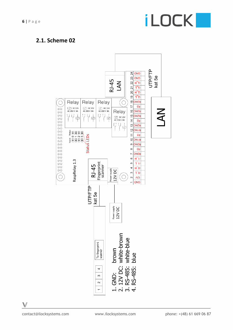
2. Fingerprint scanner connection. All wiring should be connected according to the diagram shown on Scheme 02 or Scheme 03
of the technical documentation.
The connection of the system must be carried out by a person with appropriate electrical
knowledge. Check the quality and correctness of the connections before the first use.
Be careful and remember to disconnect the equipment from the power supply when the cables
are connecting.
The Fig. 1 shows the description of the RJ45 T-568B plug. The plug is placed in the corresponding
slot on the iLock control unit.
Fig. 1 Rj45 plug with T-568B connection standard.
Please see how to connect the control unit to the fingerprint reader. Table 1 contains the
complete assignment of 4 wires used to connect the power supply and the communication bus
between the fingerprint reader and iLock.

5 | P a g e
[email protected] www.ilocksystems.com phone: +(48) 61 669 06 87
Numbering on the terminal
block (Fingerprint scanner)
Colour of the
cord
Numbering on the terminal block
(control unit) – DESCRIPTION
ABOVE
UTP/FTP to
fingerprint
scanner
4 Blue 4
3 White-blue 5
2 White-brown 7
1 Brown 8
Table 1 Connection of the fingerprint scanner.
Connection of the basic components can be found in Scheme 02 of the technical documentation.
Connect the UTP/FTP Cat 5e cable from the fingerprint reader to the appropriate RJ-45 socket.
Connect readers according to schematic: Scheme 02. If more than one reader is used, use
an additional connector block (see Scheme 03).


8 | P a g e
[email protected] www.ilocksystems.com phone: +(48) 61 669 06 87
3. Connection of electric strike with door status microswitch.
All wiring should be connected according to the diagram shown on Scheme 04 of the technical
documentation.
The connection of the system must be carried out by a person with appropriate electrical
knowledge. Check the quality and correctness of the connections before the first use.
Be careful and remember to disconnect the equipment from the power supply when the cables
are connecting.
Connection of the electric strike with external power supply:
Positive output of the external power supply (V+) should be connected to one of the unused relay
inputs: R0, R1, R2 or R3.
Connect the corresponding input: R0NO, R1NO, R2NO or R3NO (Depending on the selected relay,
for example, when V+ is connected to the input R0, select R0NO) to one of the double connector
jacks of electric strike. Negative output V- of the external power supply connects directly to the
second connector jack on the electric strike.
Door status microswitch (triple connector jack on the electric strike) should be connected to the
appropriate input on the iLock control unit, i.e. if electric strike is connected to the R0 and R0NO
then output C of the microswitch should be connected to IOL input. Connect the NO output to the
GND from the control unit (any output can be used).
Once all components have been correctly connected, connect the iLock to the LAN and the
appropriate power supply (also to the power supply of the electric strike).


10 | P a g e
[email protected] www.ilocksystems.com phone: +(48) 61 669 06 87
4. Connection of Somfy Inteo RTS All wiring should be connected according to the diagram shown on Scheme 05 of the technical
documentation.
The Scheme shows the connection of the Somfy Inteo RTS device only, connection diagrams
of readers or other components are presented in other chapters.
The connection of the system must be carried out by a person with appropriate electrical
knowledge. Check the quality and correctness of the connections before the first use.
Be careful and remember to disconnect the equipment from the power supply when the cables
are connecting.
Connect Somfy Inteo RTS connectors to selected unused relay outputs of iLock. Output C
(connector number 3) should be connected to the common inputs on the control unit e.g. R0 i R1.
Connectors 5 (down arrow) and 4 (up arrow), should be connected to the corresponding normally
open inputs of selected relays.
For example if output C (connector number 3) of the Somfy Inteo RTS device is connected to the
R0 and R1, the 5 connector (down arrow) should be connected to the R0NO and connector 4
(arrow up) analogically to R1NO.
Once all components have been correctly connected, connect the iLock to the LAN and the
appropriate power supply (also to the Somfy device, N – neutral, L - phase).


12 | P a g e
[email protected] www.ilocksystems.com phone: +(48) 61 669 06 87
5. Connection of EAV 3 Winkhaus lock and reel switch
All wiring should be connected according to the diagram shown on Scheme 06 of the technical
documentation.
The Scheme shows the connection of EAV 3 Winkhaus lock and reel switch only, connection
diagrams of readers or other components are presented in other chapters.
The connection of the system must be carried out by a person with appropriate electrical
knowledge. Check the quality and correctness of the connections before the first use.
Be careful and remember to disconnect the equipment from the power supply when the cables
are connecting.
a) Connection of EAV 3 Winkhaus lock The wires from the EAV 3 Winkhaus plug must be connected to the iLock control unit.
Socket Wire colour
1 White
2 Brown
3 Green
Not used Yellow
Not used Grey
Not used Pink
Table 2 Assignment of connections on the connecting block
From the connecting block (according to Table 2) wire number 1 (white) should be connected to
the selected unused relay outputs of iLock (e.g. R1), analogically the green wire (number 3) from
connecting block should be connected to normally open relay output (According to the example
above: R1NO).
Remember, to be sure that the EAV 3 Winkhaus lock is working properly the compatible power
supply is required.
Positive output of the power supply V+ should be connected to the 1 socket on the connecting
block, negative output of the power supply V- should be connected to the socket number 2 on the
connecting block also.

13 | P a g e
[email protected] www.ilocksystems.com phone: +(48) 61 669 06 87
b) Connection of the reel switch for door status
One of the wires from the reel switch should be connected to the GND output on the iLock control
unit (any output can be used). Second wire should be connected to the input (activated with low
signal) which number is corresponding to number of the relay used for the lock. So if the lock
if the lock is connected to the relay number 1 (R1) the second reel switch wire should be
connected to I1L input on iLock control unit.
Once all components have been correctly connected, connect the iLock to the LAN and the
appropriate power supply (also for the lock).


15 | P a g e
[email protected] www.ilocksystems.com phone: +(48) 61 669 06 87
6. Connection of Portos SIR Controller
All wiring should be connected according to the diagram shown on Scheme 07A or Scheme 07B
of the technical documentation.
The Scheme shows the connection of Portos SIR Controller only, connection diagrams of readers
or other components are presented in other chapters.
The connection of the system must be carried out by a person with appropriate electrical
knowledge. Check the quality and correctness of the connections before the first use.
Be careful and remember to disconnect the equipment from the power supply when the cables
are connecting.
a) Controlling one Portos SIR.
This connection method is shown in Scheme 07A of the technical documentation.
To connect one controller to the iLock, the triple connector jack on the Portos SIR will be used.
Connectors are described by up arrow, letter P and down arrow. Output P (middle one) should be
connected to should be connected to two of the unused relay inputs e.g. R0 and R1.
Outputs which are described by arrows should be connected to normally open relay inputs
corresponding to the selected before (used for P). For example: connector described by up arrow
should be connected to R0NO and down arrow to R1NO.
For connection of the motor and power supply - please refer to the Portos SIR documentation.
Once all components have been correctly connected, connect the iLock to the LAN and the
appropriate power supply.

16 | P a g e
[email protected] www.ilocksystems.com phone: +(48) 61 669 06 87
b) Group control
This connection method is shown in Scheme 07B of the technical documentation.
To connect one controller to the iLock, the fivefold connector jack (on the left side of the device)
on the Portos SIR will be used. Connectors are described by letters: PE, L, N and shapes: up arrow,
down arrow. Output L should be connected to should be connected to two of the unused relay
inputs e.g. R0 and R1
Outputs which are described by arrows should be connected to normally open relay inputs
corresponding to the selected before (used for L). For example: connector described by up arrow
should be connected to R0NO and down arrow to R1NO.
For connection of the motor and power supply - please refer to the Portos SIR documentation.
Once all components have been correctly connected, connect the iLock to the LAN and the
appropriate power supply.

