illustrated parts breakdown manual ez loader model ez12 · pdf fileez loader model ez12 xtreme...
TRANSCRIPT

Preliminary Manual August 23, 2007
Illustrated Parts Breakdown Manual
EZ LOADER
Model EZ12
Xtreme Manufacturing 1415 West Bonanza Road
Las Vegas, NV 89106 (702) 858-2404
www.xtrememanufacturing.com
Copyr ight © 2007 By Xt reme Manufactur ing

Xtreme Manufacturing EZ12 Easy Loader
August 23, 2007 Preliminary Manual A
List of Effective Pages
This manual consists of 94 pages as listed below:
Outside title page Inside title page Pages A through D Pages i through iv Pages 1-1 through 1-2 Pages 2-1 through 2-36 Pages 3-1 through 3-8 Pages 4-1 through 4-14 Pages 5-1 through 5-10 Index 1-1 through Index 1-20 Warranty 1 through Warranty 2 Inside back cover Outside back cover
Xtreme Manufacturing EZ12 Easy Loader
August 23, 2007 Preliminary Manual B
Service Bulletins
The following service bulletins have been incorporated in this manual:
Title Bulletin No. Comments
Xtreme Manufacturing EZ12 Easy Loader
August 23, 2007 Preliminary Manual C
Design Change Notices
The following design change notices have been incorporated in this manual:
Title Design Change Notice No. Comments

Xtreme Manufacturing EZ12 Easy Loader
August 23, 2007 Preliminary Manual D
THIS PAGE INTENTIONALLY LEFT BLANK

Xtreme Manufacturing EZ12 Easy Loader
August 23, 2007 Preliminary Manual i
Table of Contents
Chap./Par. Title Page
List of Effective Pages........................................................................................................................ A
Service Bulletins ................................................................................................................................. B
Design Change Notices ...................................................................................................................... C
Alphabetical List of Parts Breakdowns ............................................................................................ ii
Numerical List of Parts Breakdowns ................................................................................................ v
Section 1 – General Information ...................................................................................................... 1-1
Section 2 – Chassis .......................................................................................................................... 2-1
Section 3 – Decals............................................................................................................................. 3-1
Section 4 – Hydraulic System .......................................................................................................... 4-1
Section 5 – Electrical System .......................................................................................................... 5-1
Numerical and Alphabetical Indexes .............................................................................................. Index 1

Xtreme Manufacturing EZ12 Easy Loader
August 23, 2007 Preliminary Manual ii
Alphabetical List of Parts Breakdowns
Title Figure No. Page No.
Backup Light Assembly......................................... 5-2...............................................................................5-4 Cable Roller Assembly........................................ 2-13.............................................................................2-35 Check Valve Assembly ......................................... 4-5.............................................................................4-10 Control Valve Assembly ........................................ 4-3...............................................................................4-6 Cylinder Linkage Assembly................................. 2-10.............................................................................2-29 Decals ................................................................... 3-1...............................................................................3-2 Dove Tail Assembly .............................................. 2-5.............................................................................2-17 Dove Tail Linkage Assembly................................. 2-7.............................................................................2-22 Dove Tail Support Assembly................................. 2-6.............................................................................2-20 Final Bed Assembly .............................................. 2-1...............................................................................2-2 Flip Tail Assembly ................................................. 2-8.............................................................................2-24 Hose and Fitting Kit............................................... 4-6.............................................................................4-12 Hydraulic Filter Assembly...................................... 4-2...............................................................................4-4 Hydraulic Tank Assembly...................................... 4-1...............................................................................4-2 Junction Assembly ................................................ 4-4...............................................................................4-8 Main Bed Assembly .............................................. 2-2...............................................................................2-8 Marker Lamp Assembly, Red................................ 5-3...............................................................................5-6 Marker Lamp Assembly, Yellow............................ 5-4...............................................................................5-8 Retractor Link Assembly ....................................... 2-9.............................................................................2-27 Tail Idler Assembly.............................................. 2-12.............................................................................2-33 Tail Latch Assembly ............................................ 2-11.............................................................................2-31 Tail Light Assembly .............................................. 5-1...............................................................................5-2 Toolbox Assembly................................................. 2-4.............................................................................2-15 Winch Assembly.................................................... 2-3.............................................................................2-13

Xtreme Manufacturing EZ12 Easy Loader
August 23, 2007 Preliminary Manual iii
Numerical List of Parts Breakdowns
Figure No. Title Page No.
2-1 ............. Final Bed Assembly................................................................................................................2-2 2-2 ............. Main Bed Assembly................................................................................................................2-8 2-3 ............. Winch Assembly ...................................................................................................................2-13 2-4 ............. Toolbox Assembly ................................................................................................................2-15 2-5 ............. Dove Tail Assembly..............................................................................................................2-17 2-6 ............. Dove Tail Support Assembly ................................................................................................2-20 2-7 ............. Dove Tail Linkage Assembly ................................................................................................2-22 2-8 ............. Flip Tail Assembly ................................................................................................................2-24 2-9 ............. Retractor Link Assembly.......................................................................................................2-27 2-10 ........... Cylinder Linkage Assembly ..................................................................................................2-29 2-11 ........... Tail Latch Assembly .............................................................................................................2-31 2-12 ........... Tail Idler Assembly ...............................................................................................................2-33 2-13 ........... Cable Roller Assembly .........................................................................................................2-35
3-1 ............. Decals.....................................................................................................................................3-2
4-1 ............. Hydraulic Tank Assembly .......................................................................................................4-2 4-2 ............. Hydraulic Filter Assembly .......................................................................................................4-4 4-3 ............. Control Valve Assembly .........................................................................................................4-6 4-4 ............. Junction Assembly..................................................................................................................4-8 4-5 ............. Check Valve Assembly.........................................................................................................4-10 4-6 ............. Hose and Fitting Kit ..............................................................................................................4-12
5-1 ............. Tail Light Assembly ................................................................................................................5-2 5-2 ............. Backup Light Assembly ..........................................................................................................5-4 5-3 ............. Marker Lamp Assembly, Red .................................................................................................5-6 5-4 ............. Marker Lamp Assembly, Yellow .............................................................................................5-8

Xtreme Manufacturing EZ12 Easy Loader
August 23, 2007 Preliminary Manual iv
THIS PAGE INTENTIONALLY LEFT BLANK
Xtreme Manufacturing EZ12 Easy Loader
August 23, 2007 Preliminary Manual 1-1
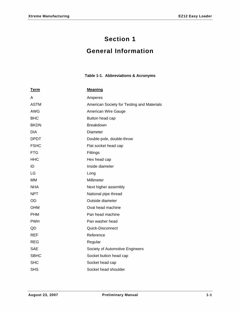
Section 1
General Information
Table 1-1. Abbreviations & Acronyms
Term Meaning
A Amperes
ASTM American Society for Testing and Materials
AWG American Wire Gauge
BHC Button head cap
BKDN Breakdown
DIA Diameter
DPDT Double-pole, double-throw
FSHC Flat socket head cap
FTG Fittings
HHC Hex head cap
ID Inside diameter
LG Long
MM Millimeter
NHA Next higher assembly
NPT National pipe thread
OD Outside diameter
OHM Oval head machine
PHM Pan head machine
PWH Pan washer head
QD Quick-Disconnect
REF Reference
REG Regular
SAE Society of Automotive Engineers
SBHC Socket button head cap
SHC Socket head cap
SHS Socket head shoulder

Xtreme Manufacturing EZ12 Easy Loader
August 23, 2007 Preliminary Manual 1-2
Term Meaning
SPDT Single-throw, double-pole
SPST Single-pole, single-throw
STR Straight
THD Thread
UNC Unified National Coarse
UNF Unified National Fine
V Volts

Xtreme Manufacturing EZ12 Easy Loader
August 23, 2007 Preliminary Manual 2-1
Section 2
Chassis

Xtreme Manufacturing EZ12 Easy Loader
August 23, 2007 Preliminary Manual 2-2
Figure 2-1. Final Bed Assembly (Sheet 1 of 4)

Xtreme Manufacturing EZ12 Easy Loader
August 23, 2007 Preliminary Manual 2-3
Figure 2-1. Final Bed Assembly (Sheet 2 of 4)
Xtreme Manufacturing EZ12 Easy Loader
August 23, 2007 Preliminary Manual 2-4
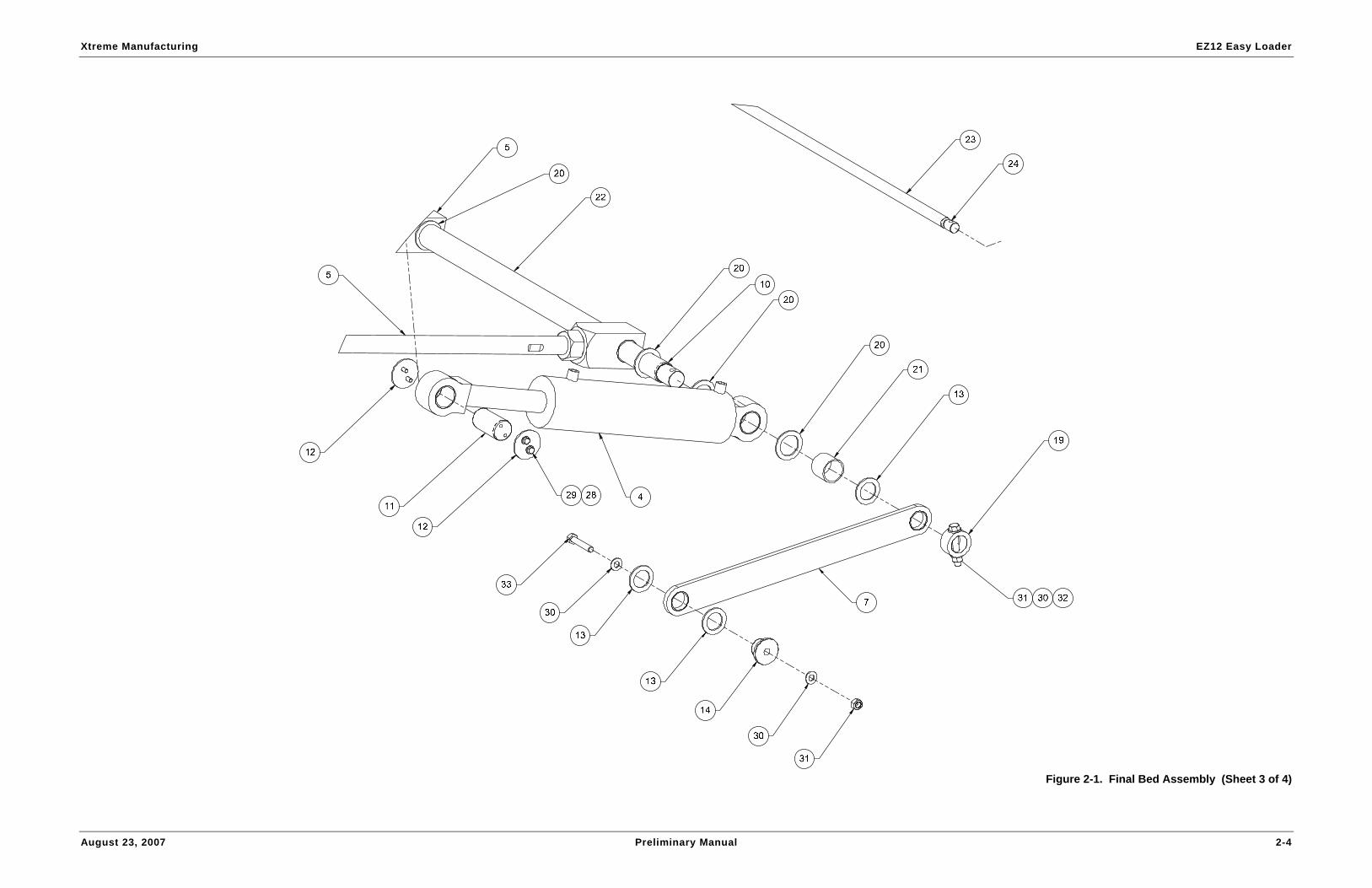
Figure 2-1. Final Bed Assembly (Sheet 3 of 4)

Xtreme Manufacturing EZ12 Easy Loader
August 23, 2007 Preliminary Manual 2-5
Figure 2-1. Final Bed Assembly (Sheet 4 of 4)

Xtreme Manufacturing EZ12 Easy Loader
August 23, 2007 Preliminary Manual 2-6
Table 2-1. Final Bed Assembly
Figure & Item No. Part No. Description Quantity Use On
– 50958-000 Final bed assembly – –
2-1-1 50841-000 Main bed assembly EZ12M 1 –
2-1-2 50840-000 Dove tail assembly EZ12M 1 –
2-1-3 50838-000 Flip tail assembly 1 –
2-1-4 50625-000 Dove tail cylinder assembly 2 –
2-1-5 50630-000 Dove tail support assembly 1 –
2-1-6 50145-000 Flip tail cylinder 1 –
2-1-7 50631-000 Dove tail linkage assembly 2 –
2-1-8 50832-000 Cable roller assembly 1 –
2-1-9 50926-000 Plate, dove tail cylinder mount 1 –
2-1-10 50667-000 Bar, dove tail cylinder mount 1 –
2-1-11 50714-000 Cylinder mount pin bar 2 –
2-1-12 50715-000 Sheet, pin retainer 4 –
2-1-13 13752-011 Mach bushing 1-1/2” x 10 GA 6 –
2-1-14 50700-000 Tail latch pivot bar 2 –
2-1-15 50694-000 Bar, linkage pin 1 –
2-1-16 50717-000 Flip tail cylinder mount pin bar 1 –
2-1-17 50718-000 Bar, flip tail cylinder mount 2 –
2-1-18 50701-000 Shaft collar tube 2 –
2-1-19 50720-000 Shaft collar tube 2 –
2-1-20 13752-014 Mach bushing 1-3/4” x 10 GA 8 –
2-1-21 50719-000 Spacer tube 2 –
2-1-22 50721-000 Spacer tube 1 –
2-1-23 50769-000 Dove tail pivot bar 1 –
2-1-24 50771-000 Pin retainer bar 2 –

Xtreme Manufacturing EZ12 Easy Loader
August 23, 2007 Preliminary Manual 2-7
Table 2-1. Final Bed Assembly
Figure & Item No. Part No. Description Quantity Use On
2-1-25 50770-000 Bar, flip tail pivot 2 –
2-1-26 50772-000 Pin retainer bar 4 –
2-1-27 60016-010 Winch guard 1 –
2-1-28 11001-005 Washer 5/16” SAE flat ASTM 16 –
2-1-29 10001-006 Screw 5/16-18UNC HHC x 3/4” 8 –
2-1-30 11001-008 Washer 1/2” SAE flat 8 –
2-1-31 10900-008 Nut 1/2-13UNC reg hex 4 –
2-1-32 10004-026 Screw 1/2-13UNC HHC x 3-1/4” 2 –
2-1-33 10004-022 Screw 1/2-13UNC HHC x 2-3/4” 2 –
2-1-34 10001-020 Screw 5/16-18UNC HHC x 2-1/2” 2 –
2-1-35 10908-005 Nut 5/16-18UNC hex lock reg 4 –
2-1-36 10001-016 Screw 5/16-18UNC HHC x 2” 2 –
2-1-37 11001-006 Washer 3/8” SAE flat 4 –
2-1-38 10002-010 Screw 3/8-16UNC HHC x 1-1/4” 4 –
Refer to Section 1 for the definition of acronyms and abbreviations used in the Description Column.

Xtreme Manufacturing EZ12 Easy Loader
August 23, 2007 Preliminary Manual 2-8
Figure 2-2. Main Bed Assembly (Sheet 1 of 3)

Xtreme Manufacturing EZ12 Easy Loader
August 23, 2007 Preliminary Manual 2-9
Figure 2-2. Main Bed Assembly (Sheet 2 of 3)

Xtreme Manufacturing EZ12 Easy Loader
August 23, 2007 Preliminary Manual 2-10
Figure 2-2. Main Bed Assembly (Sheet 3 of 3)
Xtreme Manufacturing EZ12 Easy Loader
August 23, 2007 Preliminary Manual 2-11
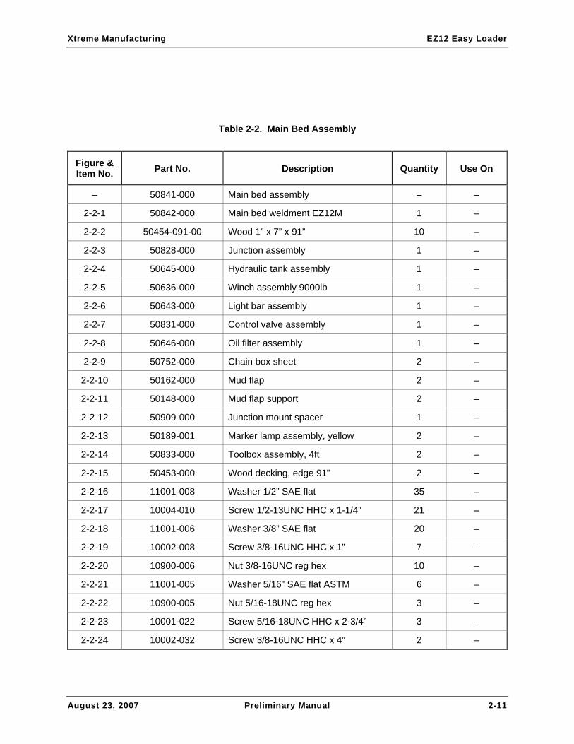
Table 2-2. Main Bed Assembly
Figure & Item No. Part No. Description Quantity Use On
– 50841-000 Main bed assembly – –
2-2-1 50842-000 Main bed weldment EZ12M 1 –
2-2-2 50454-091-00 Wood 1” x 7” x 91” 10 –
2-2-3 50828-000 Junction assembly 1 –
2-2-4 50645-000 Hydraulic tank assembly 1 –
2-2-5 50636-000 Winch assembly 9000lb 1 –
2-2-6 50643-000 Light bar assembly 1 –
2-2-7 50831-000 Control valve assembly 1 –
2-2-8 50646-000 Oil filter assembly 1 –
2-2-9 50752-000 Chain box sheet 2 –
2-2-10 50162-000 Mud flap 2 –
2-2-11 50148-000 Mud flap support 2 –
2-2-12 50909-000 Junction mount spacer 1 –
2-2-13 50189-001 Marker lamp assembly, yellow 2 –
2-2-14 50833-000 Toolbox assembly, 4ft 2 –
2-2-15 50453-000 Wood decking, edge 91” 2 –
2-2-16 11001-008 Washer 1/2” SAE flat 35 –
2-2-17 10004-010 Screw 1/2-13UNC HHC x 1-1/4” 21 –
2-2-18 11001-006 Washer 3/8” SAE flat 20 –
2-2-19 10002-008 Screw 3/8-16UNC HHC x 1” 7 –
2-2-20 10900-006 Nut 3/8-16UNC reg hex 10 –
2-2-21 11001-005 Washer 5/16” SAE flat ASTM 6 –
2-2-22 10900-005 Nut 5/16-18UNC reg hex 3 –
2-2-23 10001-022 Screw 5/16-18UNC HHC x 2-3/4” 3 –
2-2-24 10002-032 Screw 3/8-16UNC HHC x 4” 2 –

Xtreme Manufacturing EZ12 Easy Loader
August 23, 2007 Preliminary Manual 2-12
Table 2-2. Main Bed Assembly
Figure & Item No. Part No. Description Quantity Use On
2-2-25 10900-008 Nut 1/2-13UNC reg hex 14 –
2-2-26 11001-004 Washer 1/4SAE flat ASTM 16 –
2-2-27 10000-012 Screw 1/4-20UNC HHC x 1-1/2” 8 –
2-2-28 10908-004 Nut 1/4-20UNC hex lock reg 8 –
Refer to Section 1 for the definition of acronyms and abbreviations used in the Description Column.

Xtreme Manufacturing EZ12 Easy Loader
August 23, 2007 Preliminary Manual 2-13
Figure 2-3. Winch Assembly

Xtreme Manufacturing EZ12 Easy Loader
August 23, 2007 Preliminary Manual 2-14
Table 2-3. Winch Assembly
Figure & Item No. Part No. Description Quantity Use On
– 50636-000 Winch assembly – –
2-3-1 50635-000 Winch angle weldment 1 –
2-3-2 50146-000 Winch 9000 lb 1 –
2-3-3 50147-000 Winch winder level 1 –
2-3-4 11001-008 Washer 1/2” SAE flat 2 –
2-3-5 10004-018 Screw 1/2-13UNC HHC x 2-1/4” 2 –
Refer to Section 1 for the definition of acronyms and abbreviations used in the Description Column.
Xtreme Manufacturing EZ12 Easy Loader
August 23, 2007 Preliminary Manual 2-15
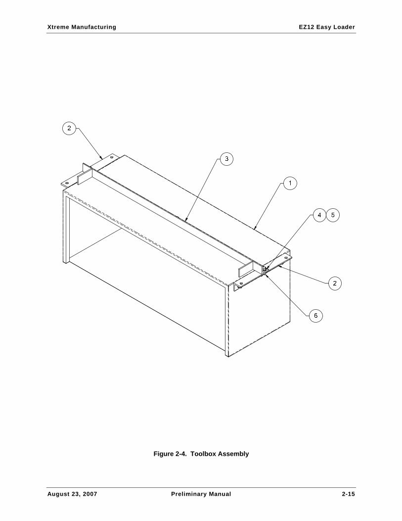
Figure 2-4. Toolbox Assembly

Xtreme Manufacturing EZ12 Easy Loader
August 23, 2007 Preliminary Manual 2-16
Table 2-4. Toolbox Assembly
Figure & Index No. Part No. Description Quantity Use On
– 50833-000 Toolbox assembly – –
2-4-1 50116-003 Toolbox, 4’ 1 –
2-4-2 50755-000 Angle, toolbox mount 2 –
2-4-3 50834-000 Toolbox mount weldment 1 –
2-4-4 11001-008 Washer 1/2” SAE flat 18 –
2-4-5 10004-010 Screw 1/2-13UNC HHC x 1-1/4” 9 –
2-4-6 10900-008 Nut 1/2-13UNC reg hex 9 –
Refer to Section 1 for the definition of acronyms and abbreviations used in the Description Column.
Xtreme Manufacturing EZ12 Easy Loader
August 23, 2007 Preliminary Manual 2-17
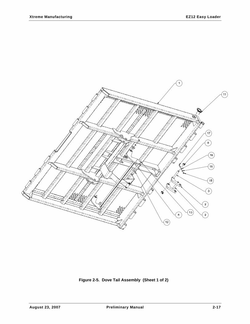
Figure 2-5. Dove Tail Assembly (Sheet 1 of 2)

Xtreme Manufacturing EZ12 Easy Loader
August 23, 2007 Preliminary Manual 2-18
Figure 2-5. Dove Tail Assembly (Sheet 2 of 2)

Xtreme Manufacturing EZ12 Easy Loader
August 23, 2007 Preliminary Manual 2-19
Table 2-5. Dove Tail Assembly
Figure & Item No. Part No. Description Quantity Use On
– 50840-000 Dove tail assembly – –
2-5-1 50839-000 Dove tail weldment EZ12M 1 –
2-5-2 50617-000 Cylinder linkage assembly 1 –
2-5-3 50694-000 Linkage pin bar 1 –
2-5-4 50619-000 Tail latch assembly 1 –
2-5-5 50950-000 Tail idler assembly 1 –
2-5-6 50104-000 Pivot pin 5” 1 –
2-5-7 50700-000 Tail latch pivot bar 2 –
2-5-8 50701-000 Shaft collar tube 2 –
2-5-9 50702-000 Hanger plate 1 –
2-5-10 13739-008 Bushing 1-1/2” ID x 1/2” LG 4 –
2-5-11 50189-000 Marker lamp assembly, red 2 –
2-5-12 11203-012 Rollpin 5/16” dia x 1-1/2” LG 2 –
2-5-13 11003-006 Washer 3/8” flat fender 2 –
2-5-14 10002-008 Screw 3/8-16UNC HHC x 1” 2 –
2-5-15 11001-008 Washer 1/2” SAE flat 2 –
2-5-16 10004-020 Screw 1/2-13UNC HHC x 2-1/2” 2 –
Refer to Section 1 for the definition of acronyms and abbreviations used in the Description Column.

Xtreme Manufacturing EZ12 Easy Loader
August 23, 2007 Preliminary Manual 2-20
3
2
2
5
5
1
1
4
4
4
4
6
6
Figure 2-6. Dove Tail Support Assembly

Xtreme Manufacturing EZ12 Easy Loader
August 23, 2007 Preliminary Manual 2-21
Table 2-6. Dove Tail Support Assembly
Figure & Item No. Part No. Description Quantity Use On
– 50630-000 Dove tail support assembly – –
2-6-1 50705-000 Bar, support pivot 2 –
2-6-2 50706-000 Bar, dove tail support 2 –
2-6-3 50707-000 Tube, dove tail support 1 –
2-6-4 13740-024 Bushing 1.75” x 1.5” 4 –
2-6-5 10901-024 Nut 1-1/2-12UNF reg hex 2 –
2-6-6 11205-020 Rollpin 1/2” dia x 2-1/2” LG 2 –
Refer to Section 1 for the definition of acronyms and abbreviations used in the Description Column.

Xtreme Manufacturing EZ12 Easy Loader
August 23, 2007 Preliminary Manual 2-22
Figure 2-7. Dove Tail Linkage Assembly

Xtreme Manufacturing EZ12 Easy Loader
August 23, 2007 Preliminary Manual 2-23
Table 2-7. Dove Tail Linkage Assembly
Figure & Item No. Part No. Description Quantity Use On
– 50631-000 Dove tail linkage assembly – –
2-7-1 50716-000 Dove tail linkage plate 1 –
2-7-2 13739-008 Bushing 1-1/2” ID x 1/2” LG 2 –
Refer to Section 1 for the definition of acronyms and abbreviations used in the Description Column.

Xtreme Manufacturing EZ12 Easy Loader
August 23, 2007 Preliminary Manual 2-24
Figure 2-8. Flip Tail Assembly (Sheet 1 of 2)

Xtreme Manufacturing EZ12 Easy Loader
August 23, 2007 Preliminary Manual 2-25
Figure 2-8. Flip Tail Assembly (Sheet 2 of 2)

Xtreme Manufacturing EZ12 Easy Loader
August 23, 2007 Preliminary Manual 2-26
Table 2-8. Flip Tail Assembly
Figure & Item No. Part No. Description Quantity Use On
– 50838-000 Flip tail assembly – –
2-8-1 50837-000 Flip tail weldment 1 –
2-8-2 50623-000 Retractor link assembly 1 –
2-8-3 50708-000 Linkage pin bar 1 –
2-8-4 50701-000 Shaft collar tube 2 –
2-8-5 50197-000 Backup light assembly 2 –
2-8-6 50196-000 Tail light assembly 2 –
2-8-7 50194-000 Marker lamp, red 3 –
2-8-8 50195-000 Light, license 1 –
2-8-9 10001-016 Screw 5/16-18UNC HHC x 2 2 –
2-8-10 11203-012 Nut 5/16-18UNC hex lock reg 2 –
Refer to Section 1 for the definition of acronyms and abbreviations used in the Description Column.

Xtreme Manufacturing EZ12 Easy Loader
August 23, 2007 Preliminary Manual 2-27
2
1
3
4
3
1
4
6
5
3
Figure 2-9. Retractor Link Assembly

Xtreme Manufacturing EZ12 Easy Loader
August 23, 2007 Preliminary Manual 2-28
Table 2-9. Retractor Link Assembly
Figure & Item No. Part No. Description Quantity Use On
– 50623-000 Retractor link assembly – –
2-9-1 50703-000 Retractor bar 2 –
2-9-2 50704-000 Linkage spacer bar 1 –
2-9-3 13737-016 Bushing 1” x 1” 4 –
2-9-4 11001-006 Washer 3/8” SAE flat 2 –
2-9-5 10002-044 Screw 3/8-16UNC HHC x 5-1/2” 1 –
2-9-6 10900-006 Nut 3/8-16UNC reg hex 1 –
Refer to Section 1 for the definition of acronyms and abbreviations used in the Description Column.

Xtreme Manufacturing EZ12 Easy Loader
August 23, 2007 Preliminary Manual 2-29
Figure 2-10. Cylinder Linkage Assembly

Xtreme Manufacturing EZ12 Easy Loader
August 23, 2007 Preliminary Manual 2-30
Table 2-10. Cylinder Linkage Assembly
Figure & Item No. Part No. Description Quantity Use On
– 50617-000 Cylinder linkage assembly – –
2-10-1 50692-000 Flip tail cylinder linkage plate 2 –
2-10-2 50693-000 Linkage spacer bar 1 –
2-10-3 13737-016 Bushing 1” x 1” 4 –
2-10-4 11001-006 Washer 3/8” SAE flat 2 –
2-10-5 10002-064 Screw 3/8-16UNC HHC x 8” 1 –
2-10-6 10900-006 Nut 3/8-16UNC reg hex 1 –
Refer to Section 1 for the definition of acronyms and abbreviations used in the Description Column.

Xtreme Manufacturing EZ12 Easy Loader
August 23, 2007 Preliminary Manual 2-31
Figure 2-11. Tail Latch Assembly

Xtreme Manufacturing EZ12 Easy Loader
August 23, 2007 Preliminary Manual 2-32
Table 2-11. Tail Latch Assembly
Figure & Item No. Part No. Description Quantity Use On
– 50619-000 Tail latch assembly – –
2-11-1 50618-000 Tail latch weldment 1 –
2-11-2 13739-008 Bushing 1-1/2” ID x 1/2” LG 2 –
Refer to Section 1 for the definition of acronyms and abbreviations used in the Description Column.
Xtreme Manufacturing EZ12 Easy Loader
August 23, 2007 Preliminary Manual 2-33
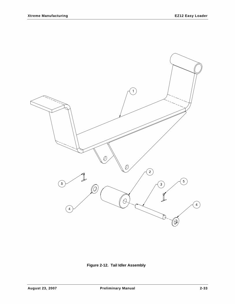
Figure 2-12. Tail Idler Assembly

Xtreme Manufacturing EZ12 Easy Loader
August 23, 2007 Preliminary Manual 2-34
Table 2-12. Tail Idler Assembly
Figure & Item No. Part No. Description Quantity Use On
– 50950-000 Tail idler assembly – –
2-12-1 50951-000 Tail idler weldment 1 –
2-12-2 50795-000 Tail idler roller 1 –
2-12-3 50796-000 Idler roller pin 1 –
2-12-4 11001-008 Washer 1/2” SAE flat 2 –
2-12-5 11236-004 Cotter pin 1/8” x 1” 2 –
Refer to Section 1 for the definition of acronyms and abbreviations used in the Description Column.

Xtreme Manufacturing EZ12 Easy Loader
August 23, 2007 Preliminary Manual 2-35
Figure 2-13. Cable Roller Assembly

Xtreme Manufacturing EZ12 Easy Loader
August 23, 2007 Preliminary Manual 2-36
Table 2-13. Cable Roller Assembly
Figure & Item No. Part No. Description Quantity Use On
– 50832-000 Cable roller assembly – –
2-13-1 50883-000 Cable roller tube 1 –
2-13-2 50882-000 Roller end bar 2 –
2-13-3 13734-016 Bushing 7/8” ID x 1” LG 4 –
Refer to Section 1 for the definition of acronyms and abbreviations used in the Description Column.

Xtreme Manufacturing EZ12 Easy Loader
August 23, 2007 Preliminary Manual 3-1
Section 3
Decals

Xtreme Manufacturing EZ12 Easy Loader
August 23, 2007 Preliminary Manual 3-2
Figure 3-1. Decals (Sheet 1 of 5)

Xtreme Manufacturing EZ12 Easy Loader
August 23, 2007 Preliminary Manual 3-3
1
2
3
Figure 3-1. Decals (Sheet 2 of 5)

Xtreme Manufacturing EZ12 Easy Loader
August 23, 2007 Preliminary Manual 3-4
4
5
6
Figure 3-1. Decals (Sheet 3 of 5)
Xtreme Manufacturing EZ12 Easy Loader
August 23, 2007 Preliminary Manual 3-5
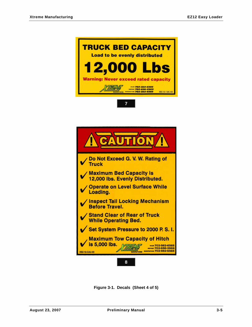
7
8
Figure 3-1. Decals (Sheet 4 of 5)

Xtreme Manufacturing EZ12 Easy Loader
August 23, 2007 Preliminary Manual 3-6
9
Figure 3-1. Decals (Sheet 5 of 5)

Xtreme Manufacturing EZ12 Easy Loader
August 23, 2007 Preliminary Manual 3-7
Table 3-1. Decals
Figure & Item No. Part No. Description Quantity Use On
3-1-1 18042-000 Decal, Xtreme Manufacturing 2 –
3-1-2 18108-000 Decal, Danger, Pinch Point 8 –
3-1-3 18112-000 Decal, Controls 1 –
3-1-4 18113-000 Decal, E-Z Loader 2 –
3-1-5 18007-999 Decal, Reflective 2 –
3-1-6 18101-000 Decal, Warning, Tail Capacity 2 –
3-1-7 18100-000 Decal, Warning, Bed Capacity 2 –
3-1-8 18102-000 Decal, Caution, Vehicle Information 2 –
3-1-9 18114-000 Decal, Vehicle Identification 1 –

Xtreme Manufacturing EZ12 Easy Loader
August 23, 2007 Preliminary Manual 3-8
THIS PAGE INTENTIONALLY LEFT BLANK

Xtreme Manufacturing EZ12 Easy Loader
August 23, 2007 Preliminary Manual 4-1
Section 4
Hydraulic System

Xtreme Manufacturing EZ12 Easy Loader
August 23, 2007 Preliminary Manual 4-2
Figure 4-1. Hydraulic Tank Assembly

Xtreme Manufacturing EZ12 Easy Loader
August 23, 2007 Preliminary Manual 4-3
Table 4-1. Hydraulic Tank Assembly
Figure & Item No. Part No. Description Quantity Use On
– 50645-000 Hydraulic tank assembly – –
4-1-1 50644-000 Hydraulic tank weldment 1 –
4-1-2 50151-000 Breather cap 3/4” NPT 1 –
4-1-3 50152-000 Fitting STR -12MP-12MJ 1 –
4-1-4 50153-000 Fitting STR -16MP-16MJ 1 –
4-1-5 50157-000 Gauge 5” sight 1 –
Refer to Section 1 for the definition of acronyms and abbreviations used in the Description Column.

Xtreme Manufacturing EZ12 Easy Loader
August 23, 2007 Preliminary Manual 4-4
2
5
4
3
1
3
Figure 4-2. Hydraulic Filter Assembly

Xtreme Manufacturing EZ12 Easy Loader
August 23, 2007 Preliminary Manual 4-5
Table 4-2. Hydraulic Filter Assembly
Figure & Item No. Part No. Description Quantity Use On
– 50646-000 Hydraulic filter assembly – –
4-2-1 50186-000 Hydraulic filter 1 –
4-2-2 50759-000 Filter mount plate 1 –
4-2-3 50152-000 Fitting STR -12MP-12MJ 2 –
4-2-4 11001-004 Washer 1/4” SAE flat ASTM 2 –
4-2-5 10000-006 Screw 1/4-20UNC HHC x 3/4” 2 –
Refer to Section 1 for the definition of acronyms and abbreviations used in the Description Column.

Xtreme Manufacturing EZ12 Easy Loader
August 23, 2007 Preliminary Manual 4-6
4 2
6
5
5
5
3
5 5
2
6
1
Figure 4-3. Control Valve Assembly

Xtreme Manufacturing EZ12 Easy Loader
August 23, 2007 Preliminary Manual 4-7
Table 4-3. Control Valve Assembly
Figure & Index No. Part No. Description Quantity Use On
– 50831-000 Control valve assembly – –
4-3-1 50184-000 Control valve 1 –
4-3-2 11699-006 Plug hex SOC -08MB 2 –
4-3-3 11699-003 Plug hex SOC -04MB 1 –
4-3-4 11666-007 Fitting elbow 90 -08MBA-06MJ 1 –
4-3-5 11660-001 Fitting STR 04MB-04MJ 5 –
4-3-6 11660-014 Fitting STR 08MB-08MJ 2 –
Refer to Section 1 for the definition of acronyms and abbreviations used in the Description Column.

Xtreme Manufacturing EZ12 Easy Loader
August 23, 2007 Preliminary Manual 4-8
Figure 4-4. Junction Assembly

Xtreme Manufacturing EZ12 Easy Loader
August 23, 2007 Preliminary Manual 4-9
Table 4-4. Junction Assembly
Figure & Item No. Part No. Description Quantity Use On
– 50828-000 Junction assembly – –
4-4-1 50777-000 Junction mount plate 1 –
4-4-2 50829-000 Check valve assembly 1 –
4-4-3 50470-000 Surface mount junction box 1 –
4-4-4 50471-000 Junction box filler plug 5 –
4-4-5 50473-000 Strain relief 3/4” 3 –
4-4-6 13051-000 Back-up alarm 1 –
4-4-7 11001-006 Washer 3/8” SAE flat 1 –
4-4-8 10900-006 Nut 3/8-16UNC reg hex 1 –
4-4-9 10156-020 Screw 3/8-16UNC FSHC x 2-1/2” 1 –
4-4-10 11001-003 Washer #10 SAE flat 8 –
4-4-11 10253-006 Screw #10-24UNC PHM x 3/4” 4 –
4-4-12 10908-003 Nut #10-24UNC hex lock 4 –
4-4-13 11001-004 Washer 1/4” SAE flat ASTM 4 –
4-4-14 10000-006 Screw 1/4-20UNC HHC x 3/4” 2 –
4-4-15 10900-004 Nut 1/4-20UNC reg hex 2 –
Refer to Section 1 for the definition of acronyms and abbreviations used in the Description Column.

Xtreme Manufacturing EZ12 Easy Loader
August 23, 2007 Preliminary Manual 4-10
1
2
3
Figure 4-5. Check Valve Assembly

Xtreme Manufacturing EZ12 Easy Loader
August 23, 2007 Preliminary Manual 4-11
Table 4-5. Check Valve Assembly
Figure & Item No. Part No. Description Quantity Use On
– 50829-000 Check valve assembly – –
4-5-1 50830-000 Check valve 1 –
4-5-2 11660-010 Fitting STR -08MB-06MJ 1 –
4-5-3 11702-006 Fitting elbow 90-06MBA-06MFS 1 –
Refer to Section 1 for the definition of acronyms and abbreviations used in the Description Column.

Xtreme Manufacturing EZ12 Easy Loader
August 23, 2007 Preliminary Manual 4-12
Figure 4-6. Hose and Fitting Kit

Xtreme Manufacturing EZ12 Easy Loader
August 23, 2007 Preliminary Manual 4-13
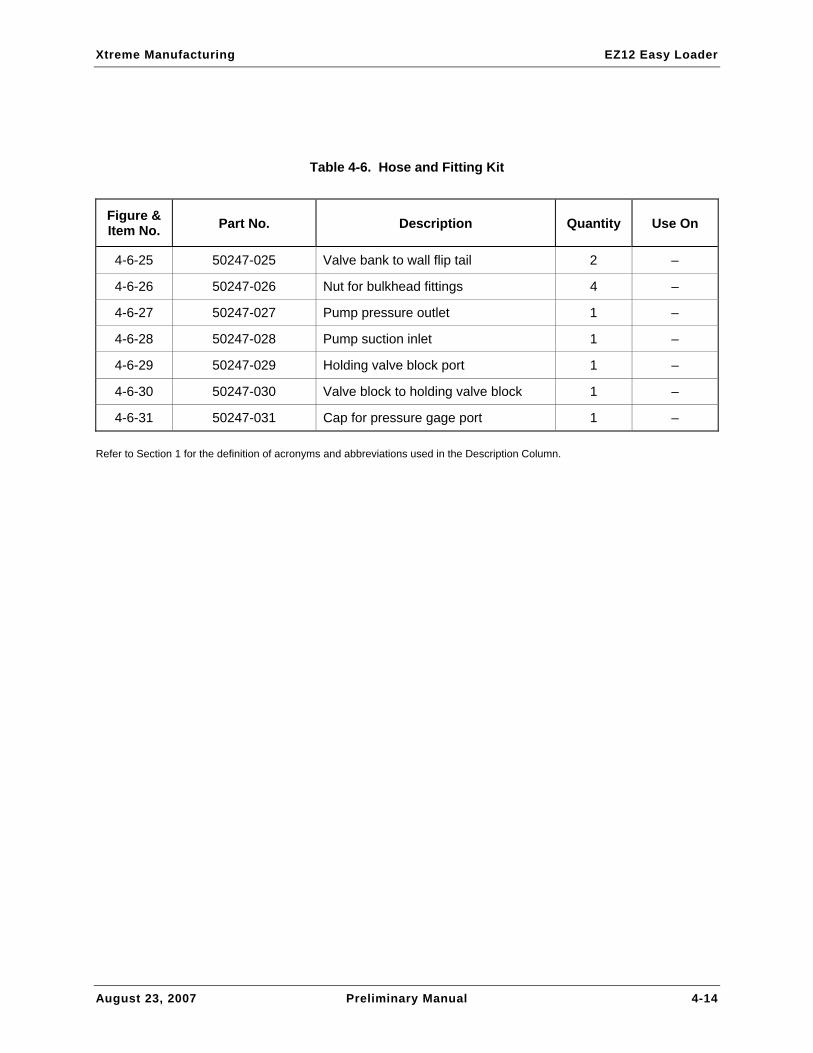
Table 4-6. Hose and Fitting Kit
Figure & Item No. Part No. Description Quantity Use On
– 50247-000 Hose and fitting kit – –
4-6-1 50247-001 Valve bank to bed 4 –
4-6-2 50247-002 Valve bank to winch 2 –
4-6-3 50247-003 Rear plate to flip tail 1 –
4-6-4 50247-004 Rear plate to flip tail 1 –
4-6-5 50247-005 Wall to dove tail cylinder 1 –
4-6-6 50247-006 Wall to dove tail cylinder 1 –
4-6-7 50247-007 Wall to dove tail cylinder 1 –
4-6-8 50247-008 Wall to dove tail cylinder 1 –
4-6-9 50247-009 Wall to valve 1 –
4-6-10 50247-010 Pump to valve body 1 –
4-6-11 50247-011 Filter to valve 1 –
4-6-12 50247-012 Filter to tank 1 –
4-6-13 50247-013 Pump to tank 1 –
4-6-14 50247-014 Winch motor 2 –
4-6-15 50247-015 A & B ports directional valve bank 5 –
4-6-16 50247-016 Valve bank outlet to filter 1 –
4-6-17 50247-017 Pump to valve bank inlet 1 –
4-6-18 50247-018 Inlet adapter for pressure gauge 1 –
4-6-19 50247-019 Holding valve block port 1 –
4-6-20 50247-020 Cylinder port 6 –
4-6-21 50247-021 In/outlet for filter 2 –
4-6-22 50247-022 Return to tank from filter 1 –
4-6-23 50247-023 Tank suction to pump 1 –
4-6-24 50247-024 Valve bank to wall dove tail 2 –
Xtreme Manufacturing EZ12 Easy Loader
August 23, 2007 Preliminary Manual 4-14
Table 4-6. Hose and Fitting Kit
Figure & Item No. Part No. Description Quantity Use On
4-6-25 50247-025 Valve bank to wall flip tail 2 –
4-6-26 50247-026 Nut for bulkhead fittings 4 –
4-6-27 50247-027 Pump pressure outlet 1 –
4-6-28 50247-028 Pump suction inlet 1 –
4-6-29 50247-029 Holding valve block port 1 –
4-6-30 50247-030 Valve block to holding valve block 1 –
4-6-31 50247-031 Cap for pressure gage port 1 –
Refer to Section 1 for the definition of acronyms and abbreviations used in the Description Column.
Xtreme Manufacturing EZ12 Easy Loader
August 23, 2007 Preliminary Manual 5-1
Section 5
Electrical System

Xtreme Manufacturing EZ12 Easy Loader
August 23, 2007 Preliminary Manual 5-2
Figure 5-1. Tail Light Assembly

Xtreme Manufacturing EZ12 Easy Loader
August 23, 2007 Preliminary Manual 5-3
Table 5-1. Tail Light Assembly
Figure & Item No. Part No. Description Quantity Use On
– 50196-000 Tail light assembly – –
5-1-1 50196-001 Light 1 –
5-1-2 50196-002 Grommet 1 –
5-1-3 50196-003 Plug 1 –
Refer to Section 1 for the definition of acronyms and abbreviations used in the Description Column.

Xtreme Manufacturing EZ12 Easy Loader
August 23, 2007 Preliminary Manual 5-4
Figure 5-2. Backup Light Assembly

Xtreme Manufacturing EZ12 Easy Loader
August 23, 2007 Preliminary Manual 5-5
Table 5-2. Backup Light Assembly
Figure & Index No. Part No. Description Quantity Use On
– 50197-000 Backup light assembly – –
5-2-1 50197-001 Light 1 –
5-2-2 50196-002 Grommet 1 –
5-2-3 50196-003 Plug 1 –
Refer to Section 1 for the definition of acronyms and abbreviations used in the Description Column.

Xtreme Manufacturing EZ12 Easy Loader
August 23, 2007 Preliminary Manual 5-6
Figure 5-3. Marker Lamp Assembly, Red

Xtreme Manufacturing EZ12 Easy Loader
August 23, 2007 Preliminary Manual 5-7
Table 5-3. Marker Lamp Assembly, Red
Figure & Item No. Part No. Description Quantity Use On
– 50189-000 Marker lamp assembly, red – –
5-3-1 50190-000 Grommet 1 –
5-3-2 50192-000 Light 1 –
5-3-3 50193-000 Plug 1 –
Refer to Section 1 for the definition of acronyms and abbreviations used in the Description Column.

Xtreme Manufacturing EZ12 Easy Loader
August 23, 2007 Preliminary Manual 5-8
Figure 5-4. Marker Lamp Assembly, Yellow

Xtreme Manufacturing EZ12 Easy Loader
August 23, 2007 Preliminary Manual 5-9
Table 5-4. Marker Lamp Assembly, Yellow
Figure & Item No. Part No. Description Quantity Use On
– 50189-001 Marker lamp assembly, yellow – –
5-4-1 50190-000 Grommet 1 –
5-4-2 50191-000 Light 1 –
5-4-3 50193-000 Plug 1 –
Refer to Section 1 for the definition of acronyms and abbreviations used in the Description Column.
Xtreme Manufacturing EZ12 Easy Loader
August 23, 2007 Preliminary Manual 5-10
THIS PAGE INTENTIONALLY LEFT BLANK

Xtreme Manufacturing EZ12 Easy Loader
August 23, 2007 Preliminary Manual Index-1
Numerical and Alphabetical Indexes
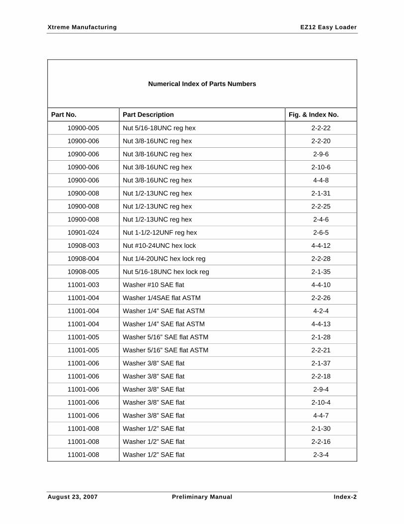
Numerical Index of Parts Numbers
Part No. Part Description Fig. & Index No.
10000-006 Screw 1/4-20UNC HHC x 3/4” 4-2-5
10000-006 Screw 1/4-20UNC HHC x 3/4” 4-4-14
10000-012 Screw 1/4-20UNC HHC x 1-1/2” 2-2-27
10001-006 Screw 5/16-18UNC HHC x 3/4” 2-1-29
10001-016 Screw 5/16-18UNC HHC x 2” 2-1-36
10001-020 Screw 5/16-18UNC HHC x 2-1/2” 2-1-34
10001-022 Screw 5/16-18UNC HHC x 2-3/4” 2-2-23
10002-008 Screw 3/8-16UNC HHC x 1” 2-2-19
10002-008 Screw 3/8-16UNC HHC x 1” 2-5-14
10002-010 Screw 3/8-16UNC HHC x 1-1/4” 2-1-38
10002-032 Screw 3/8-16UNC HHC x 4” 2-2-24
10002-044 Screw 3/8-16UNC HHC x 5-1/2” 2-9-5
10002-064 Screw 3/8-16UNC HHC x 8” 2-10-5
10004-010 Screw 1/2-13UNC HHC x 1-1/4” 2-2-17
10004-010 Screw 1/2-13UNC HHC x 1-1/4” 2-4-5
10004-018 Screw 1/2-13UNC HHC x 2-1/4” 2-3-5
10004-020 Screw 1/2-13UNC HHC x 2-1/2” 2-5-16
10004-022 Screw 1/2-13UNC HHC x 2-3/4” 2-1-33
10004-026 Screw 1/2-13UNC HHC x 3-1/4” 2-1-32
10156-020 Screw 3/8-16UNC FSHC x 2-1/2” 4-4-9
10253-006 Screw #10-24UNC PHM x 3/4” 4-4-11
10900-004 Nut 1/4-20UNC reg hex 4-4-15
Xtreme Manufacturing EZ12 Easy Loader
August 23, 2007 Preliminary Manual Index-2
Numerical Index of Parts Numbers
Part No. Part Description Fig. & Index No.
10900-005 Nut 5/16-18UNC reg hex 2-2-22
10900-006 Nut 3/8-16UNC reg hex 2-2-20
10900-006 Nut 3/8-16UNC reg hex 2-9-6
10900-006 Nut 3/8-16UNC reg hex 2-10-6
10900-006 Nut 3/8-16UNC reg hex 4-4-8
10900-008 Nut 1/2-13UNC reg hex 2-1-31
10900-008 Nut 1/2-13UNC reg hex 2-2-25
10900-008 Nut 1/2-13UNC reg hex 2-4-6
10901-024 Nut 1-1/2-12UNF reg hex 2-6-5
10908-003 Nut #10-24UNC hex lock 4-4-12
10908-004 Nut 1/4-20UNC hex lock reg 2-2-28
10908-005 Nut 5/16-18UNC hex lock reg 2-1-35
11001-003 Washer #10 SAE flat 4-4-10
11001-004 Washer 1/4SAE flat ASTM 2-2-26
11001-004 Washer 1/4” SAE flat ASTM 4-2-4
11001-004 Washer 1/4” SAE flat ASTM 4-4-13
11001-005 Washer 5/16” SAE flat ASTM 2-1-28
11001-005 Washer 5/16” SAE flat ASTM 2-2-21
11001-006 Washer 3/8” SAE flat 2-1-37
11001-006 Washer 3/8” SAE flat 2-2-18
11001-006 Washer 3/8” SAE flat 2-9-4
11001-006 Washer 3/8” SAE flat 2-10-4
11001-006 Washer 3/8” SAE flat 4-4-7
11001-008 Washer 1/2” SAE flat 2-1-30
11001-008 Washer 1/2” SAE flat 2-2-16
11001-008 Washer 1/2” SAE flat 2-3-4
Xtreme Manufacturing EZ12 Easy Loader
August 23, 2007 Preliminary Manual Index-3
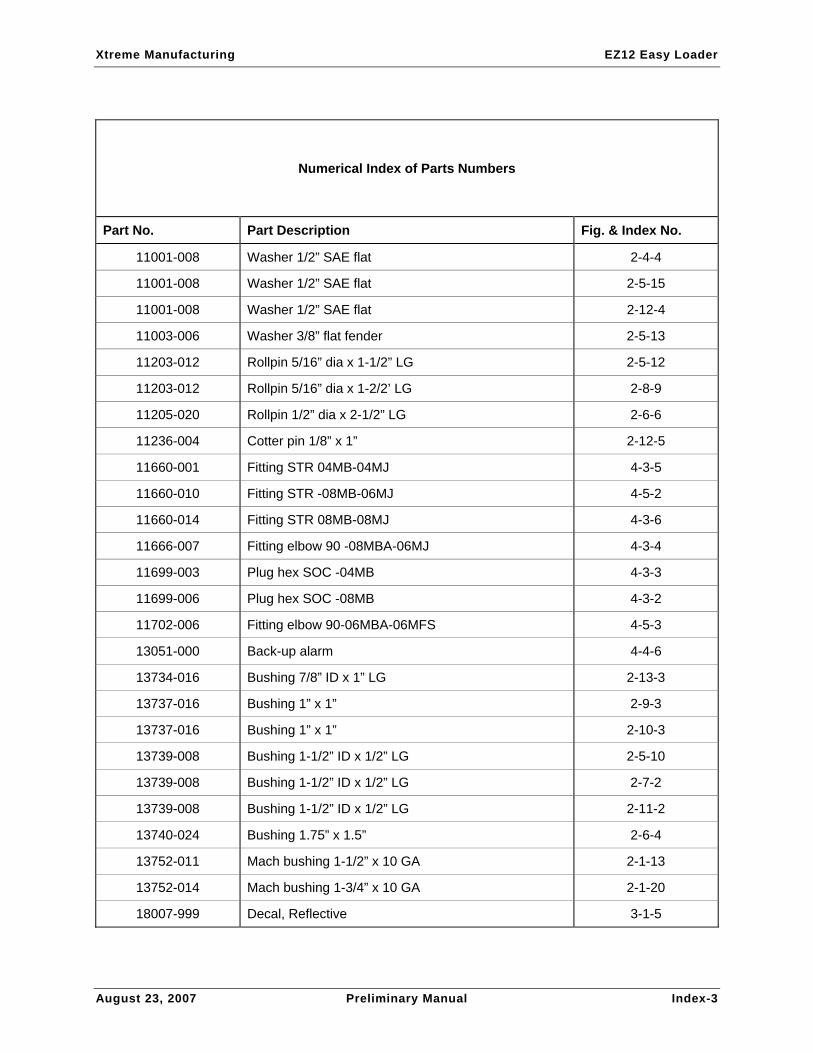
Numerical Index of Parts Numbers
Part No. Part Description Fig. & Index No.
11001-008 Washer 1/2” SAE flat 2-4-4
11001-008 Washer 1/2” SAE flat 2-5-15
11001-008 Washer 1/2” SAE flat 2-12-4
11003-006 Washer 3/8” flat fender 2-5-13
11203-012 Rollpin 5/16” dia x 1-1/2” LG 2-5-12
11203-012 Rollpin 5/16” dia x 1-2/2’ LG 2-8-9
11205-020 Rollpin 1/2” dia x 2-1/2” LG 2-6-6
11236-004 Cotter pin 1/8” x 1” 2-12-5
11660-001 Fitting STR 04MB-04MJ 4-3-5
11660-010 Fitting STR -08MB-06MJ 4-5-2
11660-014 Fitting STR 08MB-08MJ 4-3-6
11666-007 Fitting elbow 90 -08MBA-06MJ 4-3-4
11699-003 Plug hex SOC -04MB 4-3-3
11699-006 Plug hex SOC -08MB 4-3-2
11702-006 Fitting elbow 90-06MBA-06MFS 4-5-3
13051-000 Back-up alarm 4-4-6
13734-016 Bushing 7/8” ID x 1” LG 2-13-3
13737-016 Bushing 1” x 1” 2-9-3
13737-016 Bushing 1” x 1” 2-10-3
13739-008 Bushing 1-1/2” ID x 1/2” LG 2-5-10
13739-008 Bushing 1-1/2” ID x 1/2” LG 2-7-2
13739-008 Bushing 1-1/2” ID x 1/2” LG 2-11-2
13740-024 Bushing 1.75” x 1.5” 2-6-4
13752-011 Mach bushing 1-1/2” x 10 GA 2-1-13
13752-014 Mach bushing 1-3/4” x 10 GA 2-1-20
18007-999 Decal, Reflective 3-1-5

Xtreme Manufacturing EZ12 Easy Loader
August 23, 2007 Preliminary Manual Index-4
Numerical Index of Parts Numbers
Part No. Part Description Fig. & Index No.
18042-000 Decal, Xtreme Manufacturing 3-1-1
18100-000 Decal, Warning, Bed Capacity 3-1-7
18101-000 Decal, Warning, Tail Capacity 3-1-6
18102-000 Decal, Caution, Vehicle Information 3-1-8
18108-000 Decal, Danger, Pinch Point 3-1-2
18112-000 Decal, Controls 3-1-3
18113-000 Decal, E-Z Loader 3-1-4
18114-000 Decal, Vehicle Identification 3-1-9
50104-000 Pivot pin, 5” 2-5-6
50116-003 Toolbox, 4’ 2-4-1
50145-000 Flip tail cylinder 2-1-6
50146-000 Winch 9000 lb 2-3-2
50147-000 Winch winder level 2-3-3
50148-000 Mud flap support 2-2-11
50151-000 Breather cap 3/4” NPT 4-1-2
50152-000 Fitting STR -12MP-12MJ 4-1-3
50152-000 Fitting STR -12MP-12MJ 4-2-3
50153-000 Fitting STR -16MP-16MJ 4-1-4
50157-000 Gauge 5” sight 4-1-5
50162-000 Mud flap 2-2-10
50184-000 Control valve 4-3-1
50186-000 Hydraulic filter 4-2-1
50189-000 Marker lamp assembly, red 2-5-11
50189-000 Marker lamp assembly, red –
50189-001 Marker lamp assembly, yellow 2-2-13
50189-001 Marker lamp assembly, yellow –

Xtreme Manufacturing EZ12 Easy Loader
August 23, 2007 Preliminary Manual Index-5
Numerical Index of Parts Numbers
Part No. Part Description Fig. & Index No.
50190-000 Grommet 5-3-1
50190-000 Grommet 5-4-1
50191-000 Light 5-4-2
50192-000 Light 5-3-2
50193-000 Plug 5-3-3
50193-000 Plug 5-4-3
50194-000 Marker lamp, red 2-8-7
50195-000 Light, license 2-8-8
50196-000 Tail light assembly 2-8-6
50196-000 Tail light assembly –
50196-001 Light 5-1-1
50196-002 Grommet 5-1-2
50196-002 Grommet 5-2-2
50196-003 Plug 5-1-3
50196-003 Plug 5-2-3
50197-000 Backup light assembly 2-8-5
50197-000 Backup light assembly –
50197-001 Light 5-2-1
50247-000 Hose and fitting kit –
50247-001 Valve bank to bed 4-6-1
50247-002 Valve bank to winch 4-6-2
50247-003 Rear plate to flip tail 4-6-3
50247-004 Rear plate to flip tail 4-6-4
50247-005 Wall to dove tail cylinder 4-6-5
50247-006 Wall to dove tail cylinder 4-6-6
50247-007 Wall to dove tail cylinder 4-6-7

Xtreme Manufacturing EZ12 Easy Loader
August 23, 2007 Preliminary Manual Index-6
Numerical Index of Parts Numbers
Part No. Part Description Fig. & Index No.
50247-008 Wall to dove tail cylinder 4-6-8
50247-009 Wall to valve 4-6-9
50247-010 Pump to valve body 4-6-10
50247-011 Filter to valve 4-6-11
50247-012 Filter to tank 4-6-12
50247-013 Pump to tank 4-6-13
50247-014 Winch motor 4-6-14
50247-015 A & B ports directional valve bank 4-6-15
50247-016 Valve bank outlet to filter 4-6-16
50247-017 Pump to valve bank inlet 4-6-17
50247-018 Inlet adapter for pressure gauge 4-6-18
50247-019 Holding valve block port 4-6-19
50247-020 Cylinder port 4-6-20
50247-021 In/outlet for filter 4-6-21
50247-022 Return to tank from filter 4-6-22
50247-023 Tank suction to pump 4-6-23
50247-024 Valve bank to wall dove tail 4-6-24
50247-025 Valve bank to wall flip tail 4-6-25
50247-026 Nut for bulkhead fittings 4-6-26
50247-027 Pump pressure outlet 4-6-27
50247-028 Pump suction inlet 4-6-28
50247-029 Holding valve block port 4-6-29
50247-030 Valve block to holding valve block 4-6-30
50247-031 Cap for pressure gage port 4-6-31
50453-000 Wood decking, edge 91” 2-2-15
50454-091-00 Wood 1” x 7” x 91” 2-2-2

Xtreme Manufacturing EZ12 Easy Loader
August 23, 2007 Preliminary Manual Index-7
Numerical Index of Parts Numbers
Part No. Part Description Fig. & Index No.
50470-000 Surface mount junction box 4-4-3
50471-000 Junction box filler plug 4-4-4
50473-000 Strain relief 3/4” 4-4-5
50617-000 Cylinder linkage assembly 2-5-2
50617-000 Cylinder linkage assembly –
50618-000 Tail latch weldment 2-11-1
50619-000 Tail latch assembly 2-5-4
50619-000 Tail latch assembly –
50623-000 Retractor link assembly 2-8-2
50623-000 Retractor link assembly –
50625-000 Dove tail cylinder assembly 2-1-4
50630-000 Dove tail support assembly 2-1-5
50630-000 Dove tail support assembly –
50631-000 Dove tail linkage assembly 2-1-7
50631-000 Dove tail linkage assembly –
50635-000 Winch angle weldment 2-3-1
50636-000 Winch assembly 9000lb 2-2-5
50636-000 Winch assembly –
50643-000 Light bar assembly 2-2-6
50644-000 Hydraulic tank weldment 4-1-1
50645-000 Hydraulic tank assembly 2-2-4
50645-000 Hydraulic tank assembly –
50646-000 Oil filter assembly 2-2-8
50646-000 Hydraulic filter assembly –
50667-000 Bar, dove tail cylinder mount 2-1-10
50692-000 Flip tail cylinder linkage plate 2-10-1

Xtreme Manufacturing EZ12 Easy Loader
August 23, 2007 Preliminary Manual Index-8
Numerical Index of Parts Numbers
Part No. Part Description Fig. & Index No.
50693-000 Linkage spacer bar 2-10-2
50694-000 Bar, linkage pin 2-1-15
50694-000 Linkage pin bar 2-5-3
50700-000 Tail latch pivot bar 2-1-14
50700-000 Tail latch pivot bar 2-5-7
50701-000 Shaft collar tube 2-1-18
50701-000 Shaft collar tube 2-5-8
50701-000 Shaft collar tube 2-8-4
50702-000 Hanger plate 2-5-9
50703-000 Retractor bar 2-9-1
50704-000 Linkage spacer bar 2-9-2
50705-000 Bar, support pivot 2-6-1
50706-000 Bar, dove tail support 2-6-2
50707-000 Tube, dove tail support 2-6-3
50708-000 Linkage pin bar 2-8-3
50714-000 Cylinder mount pin bar 2-1-11
50715-000 Sheet, pin retainer 2-1-12
50716-000 Dove tail linkage plate 2-7-1
50717-000 Flip tail cylinder mount pin bar 2-1-16
50718-000 Bar, flip tail cylinder mount 2-1-17
50719-000 Spacer tube 2-1-21
50720-000 Shaft collar tube 2-1-19
50721-000 Spacer tube 2-1-22
50752-000 Chain box sheet 2-2-9
50755-000 Angle, toolbox mount 2-4-2
50759-000 Filter mount plate 4-2-2

Xtreme Manufacturing EZ12 Easy Loader
August 23, 2007 Preliminary Manual Index-9
Numerical Index of Parts Numbers
Part No. Part Description Fig. & Index No.
50769-000 Dove tail pivot bar 2-1-23
50770-000 Bar, flip tail pivot 2-1-25
50771-000 Pin retainer bar 2-1-24
50772-000 Pin retainer bar 2-1-26
50777-000 Junction mount plate 4-4-1
50795-000 Tail idler roller 2-12-2
50796-000 Idler roller pin 2-12-3
50828-000 Junction assembly 2-2-3
50828-000 Junction assembly –
50829-000 Check valve assembly 4-4-2
50829-000 Check valve assembly –
50830-000 Check valve 4-5-1
50831-000 Control valve assembly 2-2-7
50831-000 Control valve assembly –
50832-000 Cable roller assembly 2-1-8
50832-000 Cable roller assembly –
50833-000 Toolbox assembly, 4ft 2-2-14
50833-000 Toolbox assembly –
50834-000 Toolbox mount weldment 2-4-3
50837-000 Flip tail weldment 2-8-1
50838-000 Flip tail assembly 2-1-3
50838-000 Flip tail assembly –
50839-000 Dove tail weldment EZ12M 2-5-1
50840-000 Dove tail assembly EZ12M 2-1-2
50840-000 Dove tail assembly –
50841-000 Main bed assembly EZ12M 2-1-1

Xtreme Manufacturing EZ12 Easy Loader
August 23, 2007 Preliminary Manual Index-10
Numerical Index of Parts Numbers
Part No. Part Description Fig. & Index No.
50841-000 Main bed assembly –
50841-000 Main bed assembly –
50842-000 Main bed weldment EZ12M 2-2-1
50882-000 Roller end bar 2-13-2
50883-000 Cable roller tube 2-13-1
50909-000 Junction mount spacer 2-2-12
50926-000 Plate, dove tail cylinder mount 2-1-9
50950-000 Tail idler assembly 2-5-5
50950-000 Tail idler assembly –
50951-000 Tail idler weldment 2-12-1
50958-000 Final bed assembly –
50958-000 Final bed assembly –
60016-010 Winch guard 2-1-27

Xtreme Manufacturing EZ12 Easy Loader
August 23, 2007 Preliminary Manual Index-11
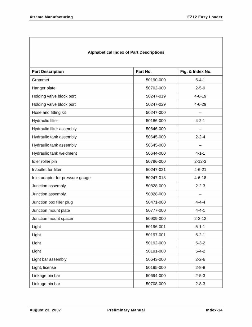
Alphabetical Index of Part Descriptions
Part Description Part No. Fig. & Index No.
A & B ports directional valve bank 50247-015 4-6-15
Angle, toolbox mount 50755-000 2-4-2
Back-up alarm 13051-000 4-4-6
Backup light assembly 50197-000 2-8-5
Backup light assembly 50197-000 –
Bar, dove tail cylinder mount 50667-000 2-1-10
Bar, dove tail support 50706-000 2-6-2
Bar, flip tail cylinder mount 50718-000 2-1-17
Bar, flip tail pivot 50770-000 2-1-25
Bar, linkage pin 50694-000 2-1-15
Bar, support pivot 50705-000 2-6-1
Breather cap 3/4” NPT 50151-000 4-1-2
Bushing 1.75” x 1.5” 13740-024 2-6-4
Bushing 1” x 1” 13737-016 2-9-3
Bushing 1” x 1” 13737-016 2-10-3
Bushing 1-1/2” ID x 1/2” LG 13739-008 2-5-10
Bushing 1-1/2” ID x 1/2” LG 13739-008 2-7-2
Bushing 1-1/2” ID x 1/2” LG 13739-008 2-11-2
Bushing 7/8” ID x 1” LG 13734-016 2-13-3
Cable roller assembly 50832-000 2-1-8
Cable roller assembly 50832-000 –
Cable roller tube 50883-000 2-13-1
Cap for pressure gage port 50247-031 4-6-31
Chain box sheet 50752-000 2-2-9
Check valve 50830-000 4-5-1
Xtreme Manufacturing EZ12 Easy Loader
August 23, 2007 Preliminary Manual Index-12
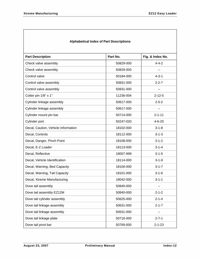
Alphabetical Index of Part Descriptions
Part Description Part No. Fig. & Index No.
Check valve assembly 50829-000 4-4-2
Check valve assembly 50829-000 –
Control valve 50184-000 4-3-1
Control valve assembly 50831-000 2-2-7
Control valve assembly 50831-000 –
Cotter pin 1/8” x 1” 11236-004 2-12-5
Cylinder linkage assembly 50617-000 2-5-2
Cylinder linkage assembly 50617-000 –
Cylinder mount pin bar 50714-000 2-1-11
Cylinder port 50247-020 4-6-20
Decal, Caution, Vehicle Information 18102-000 3-1-8
Decal, Controls 18112-000 3-1-3
Decal, Danger, Pinch Point 18108-000 3-1-2
Decal, E-Z Loader 18113-000 3-1-4
Decal, Reflective 18007-999 3-1-5
Decal, Vehicle Identification 18114-000 3-1-9
Decal, Warning, Bed Capacity 18100-000 3-1-7
Decal, Warning, Tail Capacity 18101-000 3-1-6
Decal, Xtreme Manufacturing 18042-000 3-1-1
Dove tail assembly 50840-000 –
Dove tail assembly EZ12M 50840-000 2-1-2
Dove tail cylinder assembly 50625-000 2-1-4
Dove tail linkage assembly 50631-000 2-1-7
Dove tail linkage assembly 50631-000 –
Dove tail linkage plate 50716-000 2-7-1
Dove tail pivot bar 50769-000 2-1-23
Xtreme Manufacturing EZ12 Easy Loader
August 23, 2007 Preliminary Manual Index-13
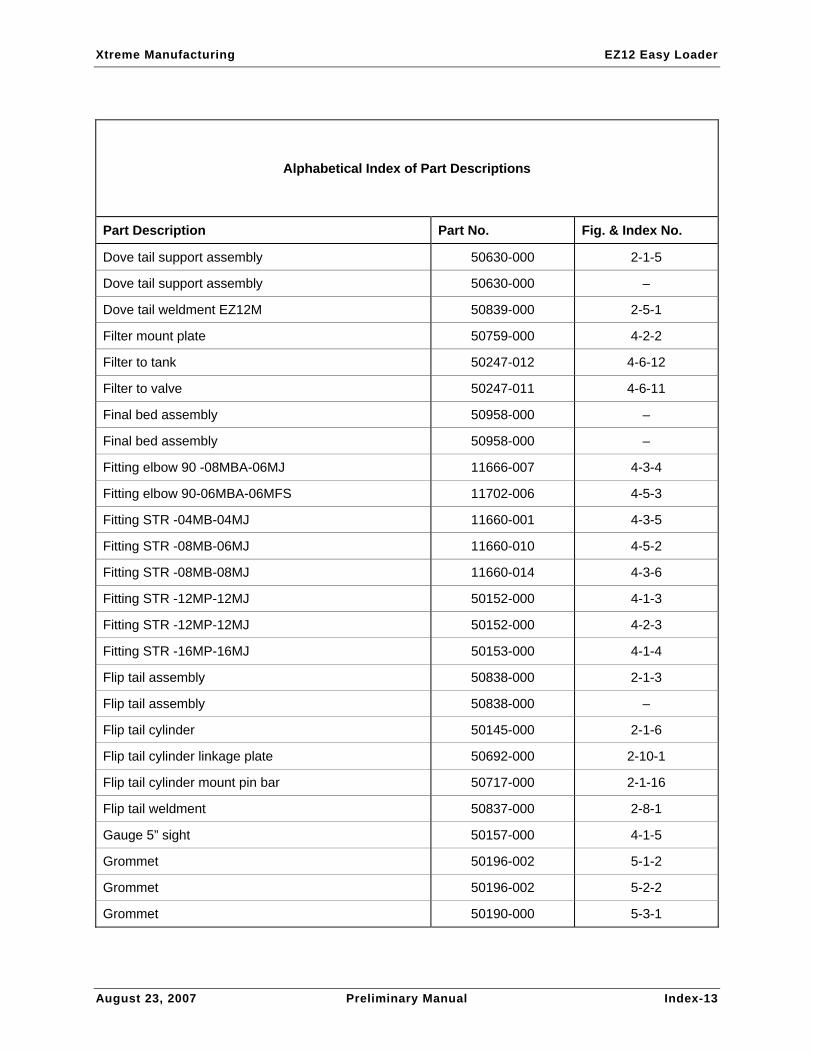
Alphabetical Index of Part Descriptions
Part Description Part No. Fig. & Index No.
Dove tail support assembly 50630-000 2-1-5
Dove tail support assembly 50630-000 –
Dove tail weldment EZ12M 50839-000 2-5-1
Filter mount plate 50759-000 4-2-2
Filter to tank 50247-012 4-6-12
Filter to valve 50247-011 4-6-11
Final bed assembly 50958-000 –
Final bed assembly 50958-000 –
Fitting elbow 90 -08MBA-06MJ 11666-007 4-3-4
Fitting elbow 90-06MBA-06MFS 11702-006 4-5-3
Fitting STR -04MB-04MJ 11660-001 4-3-5
Fitting STR -08MB-06MJ 11660-010 4-5-2
Fitting STR -08MB-08MJ 11660-014 4-3-6
Fitting STR -12MP-12MJ 50152-000 4-1-3
Fitting STR -12MP-12MJ 50152-000 4-2-3
Fitting STR -16MP-16MJ 50153-000 4-1-4
Flip tail assembly 50838-000 2-1-3
Flip tail assembly 50838-000 –
Flip tail cylinder 50145-000 2-1-6
Flip tail cylinder linkage plate 50692-000 2-10-1
Flip tail cylinder mount pin bar 50717-000 2-1-16
Flip tail weldment 50837-000 2-8-1
Gauge 5” sight 50157-000 4-1-5
Grommet 50196-002 5-1-2
Grommet 50196-002 5-2-2
Grommet 50190-000 5-3-1
Xtreme Manufacturing EZ12 Easy Loader
August 23, 2007 Preliminary Manual Index-14
Alphabetical Index of Part Descriptions
Part Description Part No. Fig. & Index No.
Grommet 50190-000 5-4-1
Hanger plate 50702-000 2-5-9
Holding valve block port 50247-019 4-6-19
Holding valve block port 50247-029 4-6-29
Hose and fitting kit 50247-000 –
Hydraulic filter 50186-000 4-2-1
Hydraulic filter assembly 50646-000 –
Hydraulic tank assembly 50645-000 2-2-4
Hydraulic tank assembly 50645-000 –
Hydraulic tank weldment 50644-000 4-1-1
Idler roller pin 50796-000 2-12-3
In/outlet for filter 50247-021 4-6-21
Inlet adapter for pressure gauge 50247-018 4-6-18
Junction assembly 50828-000 2-2-3
Junction assembly 50828-000 –
Junction box filler plug 50471-000 4-4-4
Junction mount plate 50777-000 4-4-1
Junction mount spacer 50909-000 2-2-12
Light 50196-001 5-1-1
Light 50197-001 5-2-1
Light 50192-000 5-3-2
Light 50191-000 5-4-2
Light bar assembly 50643-000 2-2-6
Light, license 50195-000 2-8-8
Linkage pin bar 50694-000 2-5-3
Linkage pin bar 50708-000 2-8-3

Xtreme Manufacturing EZ12 Easy Loader
August 23, 2007 Preliminary Manual Index-15
Alphabetical Index of Part Descriptions
Part Description Part No. Fig. & Index No.
Linkage spacer bar 50704-000 2-9-2
Linkage spacer bar 50693-000 2-10-2
Mach bushing 1-1/2” x 10 GA 13752-011 2-1-13
Mach bushing 1-3/4” x 10 GA 13752-014 2-1-20
Main bed assembly 50841-000 –
Main bed assembly 50841-000 –
Main bed assembly EZ12M 50841-000 2-1-1
Main bed weldment EZ12M 50842-000 2-2-1
Marker lamp assembly, red 50189-000 2-5-11
Marker lamp assembly, red 50189-000 –
Marker lamp assembly, yellow 50189-001 2-2-13
Marker lamp assembly, yellow 50189-001 –
Marker lamp, red 50194-000 2-8-7
Mud flap 50162-000 2-2-10
Mud flap support 50148-000 2-2-11
Nut #10-24UNC hex lock 10908-003 4-4-12
Nut 1/2-13UNC reg hex 10900-008 2-1-31
Nut 1/2-13UNC reg hex 10900-008 2-2-25
Nut 1/2-13UNC reg hex 10900-008 2-4-6
Nut 1/4-20UNC hex lock reg 10908-004 2-2-28
Nut 1/4-20UNC reg hex 10900-004 4-4-15
Nut 1-1/2-12UNF reg hex 10901-024 2-6-5
Nut 3/8-16UNC reg hex 10900-006 2-2-20
Nut 3/8-16UNC reg hex 10900-006 2-9-6
Nut 3/8-16UNC reg hex 10900-006 2-10-6
Nut 3/8-16UNC reg hex 10900-006 4-4-8

Xtreme Manufacturing EZ12 Easy Loader
August 23, 2007 Preliminary Manual Index-16
Alphabetical Index of Part Descriptions
Part Description Part No. Fig. & Index No.
Nut 5/16-18UNC hex lock reg 10908-005 2-1-35
Nut 5/16-18UNC reg hex 10900-005 2-2-22
Nut for bulkhead fittings 50247-026 4-6-26
Oil filter assembly 50646-000 2-2-8
Pin retainer bar 50771-000 2-1-24
Pin retainer bar 50772-000 2-1-26
Pivot pin 5” 50104-000 2-5-6
Plate, dove tail cylinder mount 50926-000 2-1-9
Plug 50196-003 5-1-3
Plug 50196-003 5-2-3
Plug 50193-000 5-3-3
Plug 50193-000 5-4-3
Plug hex SOC -04MB 11699-003 4-3-3
Plug hex SOC -08MB 11699-006 4-3-2
Pump pressure outlet 50247-027 4-6-27
Pump suction inlet 50247-028 4-6-28
Pump to tank 50247-013 4-6-13
Pump to valve bank inlet 50247-017 4-6-17
Pump to valve body 50247-010 4-6-10
Rear plate to flip tail 50247-003 4-6-3
Rear plate to flip tail 50247-004 4-6-4
Retractor bar 50703-000 2-9-1
Retractor link assembly 50623-000 2-8-2
Retractor link assembly 50623-000 –
Return to tank from filter 50247-022 4-6-22
Roller end bar 50882-000 2-13-2
Xtreme Manufacturing EZ12 Easy Loader
August 23, 2007 Preliminary Manual Index-17
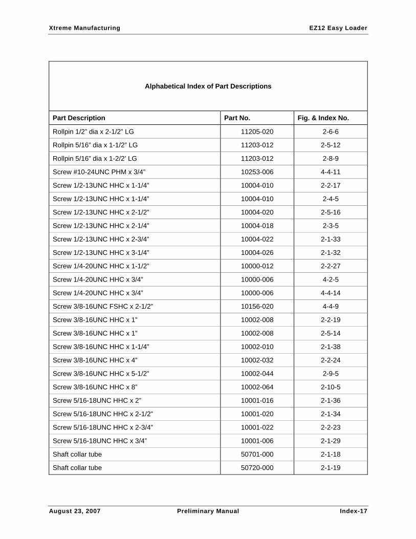
Alphabetical Index of Part Descriptions
Part Description Part No. Fig. & Index No.
Rollpin 1/2” dia x 2-1/2” LG 11205-020 2-6-6
Rollpin 5/16” dia x 1-1/2” LG 11203-012 2-5-12
Rollpin 5/16” dia x 1-2/2’ LG 11203-012 2-8-9
Screw #10-24UNC PHM x 3/4” 10253-006 4-4-11
Screw 1/2-13UNC HHC x 1-1/4” 10004-010 2-2-17
Screw 1/2-13UNC HHC x 1-1/4” 10004-010 2-4-5
Screw 1/2-13UNC HHC x 2-1/2” 10004-020 2-5-16
Screw 1/2-13UNC HHC x 2-1/4” 10004-018 2-3-5
Screw 1/2-13UNC HHC x 2-3/4” 10004-022 2-1-33
Screw 1/2-13UNC HHC x 3-1/4” 10004-026 2-1-32
Screw 1/4-20UNC HHC x 1-1/2” 10000-012 2-2-27
Screw 1/4-20UNC HHC x 3/4” 10000-006 4-2-5
Screw 1/4-20UNC HHC x 3/4” 10000-006 4-4-14
Screw 3/8-16UNC FSHC x 2-1/2” 10156-020 4-4-9
Screw 3/8-16UNC HHC x 1” 10002-008 2-2-19
Screw 3/8-16UNC HHC x 1” 10002-008 2-5-14
Screw 3/8-16UNC HHC x 1-1/4” 10002-010 2-1-38
Screw 3/8-16UNC HHC x 4” 10002-032 2-2-24
Screw 3/8-16UNC HHC x 5-1/2” 10002-044 2-9-5
Screw 3/8-16UNC HHC x 8” 10002-064 2-10-5
Screw 5/16-18UNC HHC x 2” 10001-016 2-1-36
Screw 5/16-18UNC HHC x 2-1/2” 10001-020 2-1-34
Screw 5/16-18UNC HHC x 2-3/4” 10001-022 2-2-23
Screw 5/16-18UNC HHC x 3/4” 10001-006 2-1-29
Shaft collar tube 50701-000 2-1-18
Shaft collar tube 50720-000 2-1-19

Xtreme Manufacturing EZ12 Easy Loader
August 23, 2007 Preliminary Manual Index-18
Alphabetical Index of Part Descriptions
Part Description Part No. Fig. & Index No.
Shaft collar tube 50701-000 2-5-8
Shaft collar tube 50701-000 2-8-4
Sheet, pin retainer 50715-000 2-1-12
Spacer tube 50719-000 2-1-21
Spacer tube 50721-000 2-1-22
Strain relief 3/4” 50473-000 4-4-5
Surface mount junction box 50470-000 4-4-3
Tail idler assembly 50950-000 2-5-5
Tail idler assembly 50950-000 –
Tail idler roller 50795-000 2-12-2
Tail idler weldment 50951-000 2-12-1
Tail latch assembly 50619-000 2-5-4
Tail latch assembly 50619-000 –
Tail latch pivot bar 50700-000 2-1-14
Tail latch pivot bar 50700-000 2-5-7
Tail latch weldment 50618-000 2-11-1
Tail light assembly 50196-000 2-8-6
Tail light assembly 50196-000 –
Tank suction to pump 50247-023 4-6-23
Toolbox assembly 50833-000 –
Toolbox assembly, 4ft 50833-000 2-2-14
Toolbox mount weldment 50834-000 2-4-3
Toolbox, 4’ 50116-003 2-4-1
Tube, dove tail support 50707-000 2-6-3
Valve bank outlet to filter 50247-016 4-6-16
Valve bank to bed 50247-001 4-6-1
Xtreme Manufacturing EZ12 Easy Loader
August 23, 2007 Preliminary Manual Index-19
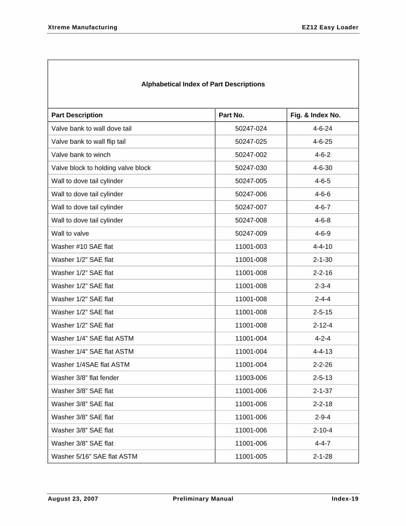
Alphabetical Index of Part Descriptions
Part Description Part No. Fig. & Index No.
Valve bank to wall dove tail 50247-024 4-6-24
Valve bank to wall flip tail 50247-025 4-6-25
Valve bank to winch 50247-002 4-6-2
Valve block to holding valve block 50247-030 4-6-30
Wall to dove tail cylinder 50247-005 4-6-5
Wall to dove tail cylinder 50247-006 4-6-6
Wall to dove tail cylinder 50247-007 4-6-7
Wall to dove tail cylinder 50247-008 4-6-8
Wall to valve 50247-009 4-6-9
Washer #10 SAE flat 11001-003 4-4-10
Washer 1/2” SAE flat 11001-008 2-1-30
Washer 1/2” SAE flat 11001-008 2-2-16
Washer 1/2” SAE flat 11001-008 2-3-4
Washer 1/2” SAE flat 11001-008 2-4-4
Washer 1/2” SAE flat 11001-008 2-5-15
Washer 1/2” SAE flat 11001-008 2-12-4
Washer 1/4” SAE flat ASTM 11001-004 4-2-4
Washer 1/4” SAE flat ASTM 11001-004 4-4-13
Washer 1/4SAE flat ASTM 11001-004 2-2-26
Washer 3/8” flat fender 11003-006 2-5-13
Washer 3/8” SAE flat 11001-006 2-1-37
Washer 3/8” SAE flat 11001-006 2-2-18
Washer 3/8” SAE flat 11001-006 2-9-4
Washer 3/8” SAE flat 11001-006 2-10-4
Washer 3/8” SAE flat 11001-006 4-4-7
Washer 5/16” SAE flat ASTM 11001-005 2-1-28

Xtreme Manufacturing EZ12 Easy Loader
August 23, 2007 Preliminary Manual Index-20
Alphabetical Index of Part Descriptions
Part Description Part No. Fig. & Index No.
Washer 5/16” SAE flat ASTM 11001-005 2-2-21
Winch 9000 lb 50146-000 2-3-2
Winch angle weldment 50635-000 2-3-1
Winch assembly 50636-000 –
Winch assembly 9000lb 50636-000 2-2-5
Winch guard 60016-010 2-1-27
Winch motor 50247-014 4-6-14
Winch winder level 50147-000 2-3-3
Wood 1” x 7” x 91” 50454-091-00 2-2-2
Wood decking, edge 91” 50453-000 2-2-15

Contact
Xtreme Manufacturing 1415 West Bonanza Road
Las Vegas, NV 89106 (702) 851-3750
www.xtrememanufacturing.com
Sales (702) 858-2404
Product Support (702) 636-2969
Engineering (702) 851-3750

Xtreme Manufacturing EZ12 Easy Loader
August 23, 2007 Preliminary Manual Warranty-1
Limited Warranty
Products Warranted
This Limited Warranty applies to new Xtreme Manufacturing brand telescopic handlers, and attachments bearing the Xtreme Manufacturing trademarks, herein referred to as Product(s), which are marketed by Xtreme Manufacturing.
Warranty Period
Xtreme Manufacturing Warrants, its Authorized Sales and Service Centers (herein referred to as “SSC”), new Product(s) to be free from defect in material or manufacture for thirty-six (36) months after date of delivery to the purchaser, except the engine which will be covered for twenty-four (24) months. Additionally, the main frame shall be free from defect in material or workmanship for ten (10) years. This Warranty is made to the original owner of the new Product(s) and is transferable for the duration of the period of coverage, to subsequent owners with prior written approval of Xtreme Manufacturing (See Limitations).
Coverage
The Xtreme Manufacturing SSC shall repair or, at Xtreme Manufacturing's option, replace any Product(s) shown to be defective in material or manufacture. Xtreme Manufacturing shall pay to the extent it has established in its applicable service policy in effect at the time of delivery of the Product(s), the cost of labor reasonably necessary to install any repaired or replaced part provided under this Warranty. The remedies set forth in this paragraph are exclusive and correction by Xtreme Manufacturing or its SSC of Product non-conformities in the manner provided above shall constitute fulfillment of all liabilities and obligations of Xtreme Manufacturing or its SSC to those entitled to the benefit of this Limited Warranty.
Exclusions
This Limited Warranty shall not apply to general maintenance services (including but not limited to, engine tune-up, brake adjustment, etc.) or to general maintenance parts (including but not limited to, fluids, lubricants, light bulbs, etc.). In addition, this Limited Warranty shall not apply to parts/options not manufactured by Xtreme Manufacturing which are warranted by their respective manufacturers including but not limited to engines, tires, batteries, etc.
Owner Responsibilities
The owner is responsible for proper maintenance of the products(s). Any improper use including failure to provide proper maintenance, operation after discovery of defective or worn parts, operation beyond rated capacity, substitution of parts not approved by Xtreme Manufacturing, alteration or repair in such a manner as in Xtreme Manufacturing's judgment adversely affects the Product(s), shall void this Warranty, if requested by Xtreme Manufacturing, product(s) or parts, for which a warranty claim is made, are to be returned, freight prepaid, to Xtreme Manufacturing.

Xtreme Manufacturing EZ12 Easy Loader
August 23, 2007 Preliminary Manual Warranty-2
Limitations
Xtreme Manufacturing's obligation under this Limited Warranty is expressly limited to the conditions as stated above and shall not include duty, taxes, or any other charges whatsoever, or any liability for direct, indirect, incidental, or consequential damage or delay. XTREME MANUFACTURING MAKES NO OTHER WARRANTY, EXPRESSED OR IMPLIED, INCLUDING WITHOUT LIMITATION ANY WARRANTY OF MERCHANTABILITY OR FITNESS FOR ANY PARTICULAR PURPOSE. No employee or representative is authorized to change this Warranty in any way or grant any other Warranty, unless such change is made in writing and signed by an officer of Xtreme Manufacturing.
Applicable Law
This Warranty shall be govemed by and interpreted in accordance with the laws of the State of Nevada. This Warranty is applicable to contracts made and performed in Nevada.
Contact
Xtreme Manufacturing, LLC 1415 West Bonanza Road
Las Vegas, NV 89106 (702) 851-3750
www.xtrememanufacturing.com
Sales (702) 858-2404
Product Support (702) 636-2969
Engineering (702) 851-3750 (702) 646-2196 (fax)
MODEL NO. ____________________
SERIAL NO. ____________________