ilc damping ring lattice – status report - computing damping ring lattice – status report louis...
TRANSCRIPT

ILC Damping Ring Lattice
– Status Report
Louis Emery and Aimin XiaoArgonne National LaboratoryPresented at KEK workshop Dec 18th, 2007

2L. Emery and A. Xiao, 12/18/07ILC Damping Ring Lattice
Outline
New 8-fold symmetric lattice on ILC Cornell wiki pages, as of 12/18/2007– Separated injection/extraction line– Lumped injection/extraction kickers (10 kV pulsers)– RF sections adjusted to accommodate SC rf cavities– Phase trombone– Circumference-adjustment chicane– Dynamic Aperture
Next iteration to be completed soon (not in time for 12/18/2007)– Go back to separated groups of kickers (7 kV pulsers)– Path length adjusters split unequally among injection and extraction
section (from FODO cell alternative) FODO-cell alternative lattice (separate talk)
– All straight-section features in two sections– DA performance comparison
Near term deliverables
3L. Emery and A. Xiao, 12/18/07ILC Damping Ring Lattice
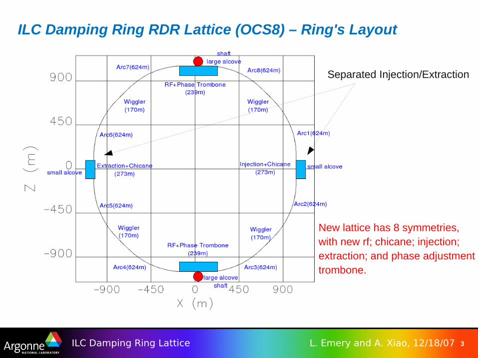
ILC Damping Ring RDR Lattice (OCS8) – Ring's Layout
Separated Injection/Extraction
New lattice has 8 symmetries,with new rf; chicane; injection;extraction; and phase adjustmenttrombone.
4L. Emery and A. Xiao, 12/18/07ILC Damping Ring Lattice
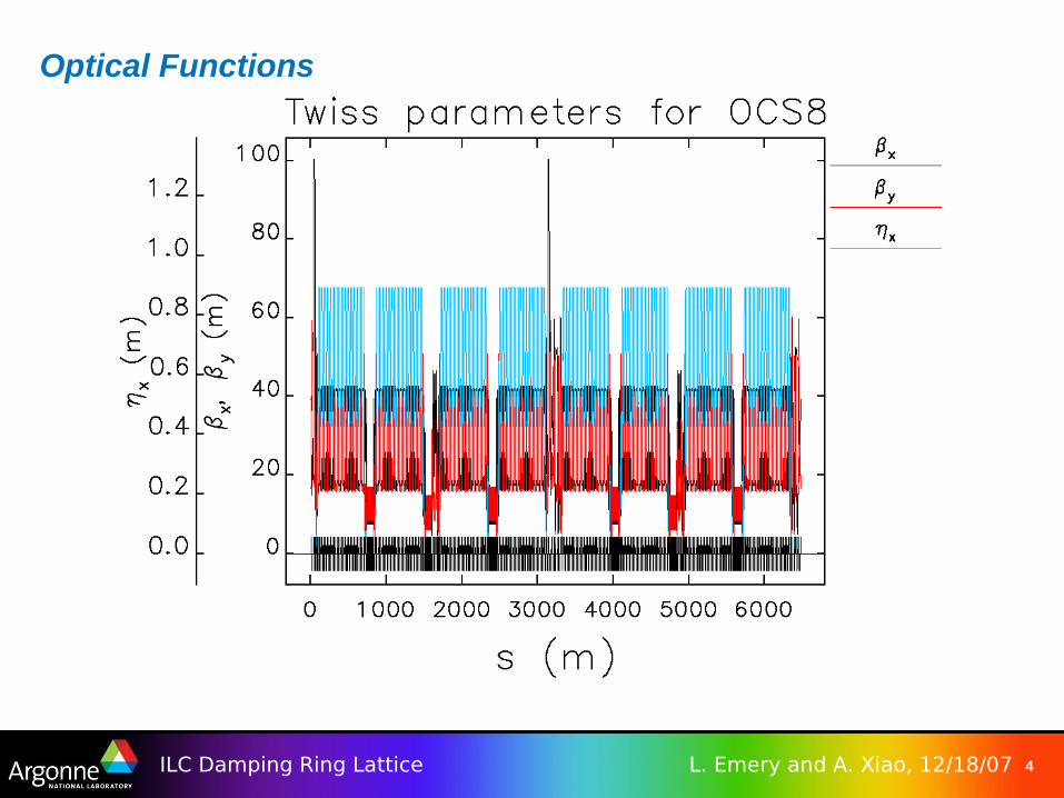
Optical Functions

5L. Emery and A. Xiao, 12/18/07ILC Damping Ring Lattice
Main Parameters

6L. Emery and A. Xiao, 12/18/07ILC Damping Ring Lattice
Lumped Injection/Extraction Line (now superceded)Injected beam
Design of Injection/Extraction
● Strength of fast strip-line kicker is very weak.● With 70 mm gap and 10 kV pulser voltage on
opposite strip-lines, 23 strip-line kickers are needed, and can be put into one straight section.
● Extraction line is the same as injection line but with fewer strip-line kickers.
7L. Emery and A. Xiao, 12/18/07ILC Damping Ring Lattice
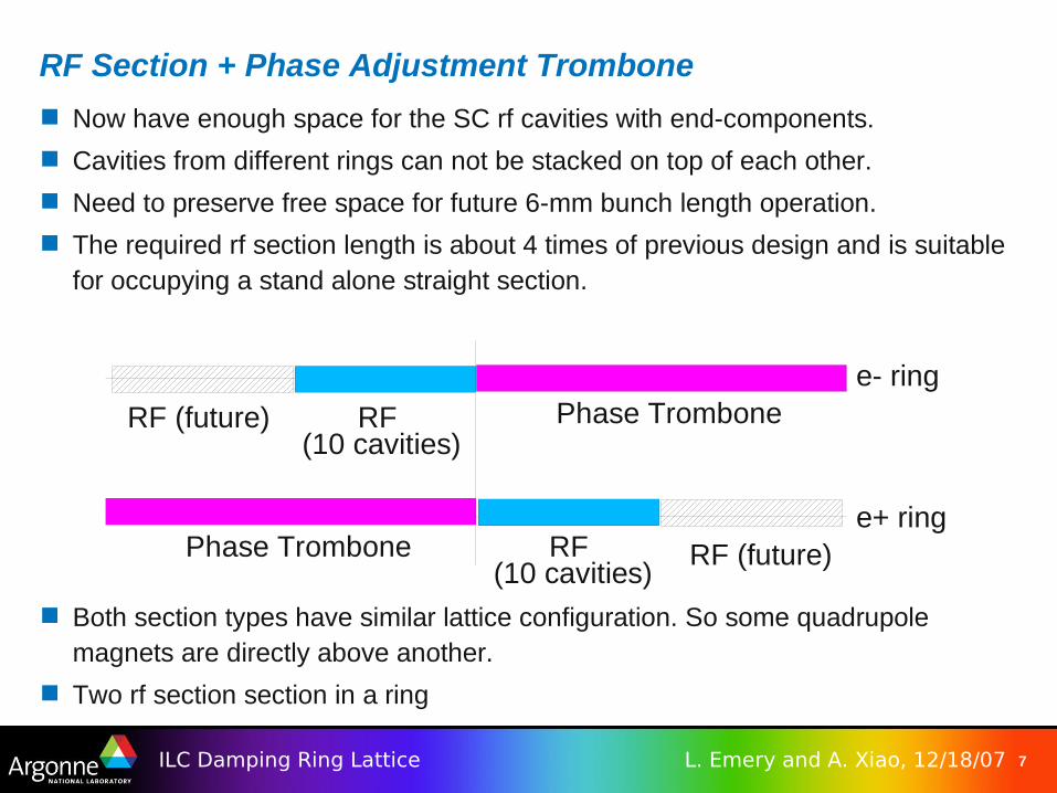
RF Section + Phase Adjustment Trombone
Now have enough space for the SC rf cavities with end-components.
Cavities from different rings can not be stacked on top of each other.
Need to preserve free space for future 6-mm bunch length operation.
The required rf section length is about 4 times of previous design and is suitable for occupying a stand alone straight section.
Both section types have similar lattice configuration. So some quadrupole magnets are directly above another.
Two rf section section in a ring
RF (10 cavities)
Phase Trombone
Phase Trombone
RF (future)
RF (future)e+ ring
e- ring
RF (10 cavities)
8L. Emery and A. Xiao, 12/18/07ILC Damping Ring Lattice
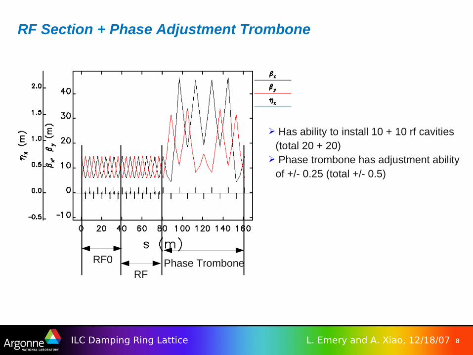
RF Section + Phase Adjustment Trombone
RF
RF0 Phase Trombone
➢ Has ability to install 10 + 10 rf cavities (total 20 + 20)
➢ Phase trombone has adjustment ability of +/- 0.25 (total +/- 0.5)

9L. Emery and A. Xiao, 12/18/07ILC Damping Ring Lattice
Circumference Adjustment Chicane
Adjustment ability: ±7.5 mm
Emittance dilution: ~15%
Total 4 cells
Min. path length
Max. path length
Make this nominal path length

10L. Emery and A. Xiao, 12/18/07ILC Damping Ring Lattice
Dynamic Aperture – Without Multipole Errors
Injection beam size: 20 mm (H) x 12 mm (V)

11L. Emery and A. Xiao, 12/18/07ILC Damping Ring Lattice
Dynamic Aperture – with Multipole Errors
Injection beam size: 20 mm (H) x 12 mm (V)
Error specified by Y. Cai (SLAC). • The original data is for bore radius of 50mm.• We scaled the data to bore radius of 30mm.• Larger magnet size (= weaker multipole error
strength) gives larger dynamic aperture.

12L. Emery and A. Xiao, 12/18/07ILC Damping Ring Lattice
Summary of work as of Nov. 2007
New injection/extraction configuration with one group of kickers– To be changed in next version
The circumference was adjusted to suit the new rf harmonic number
New rf region for accommodating large SC rf cavity
Added phase trombone (may not be needed) and chicane
The dynamic aperture had been checked with and without error
13L. Emery and A. Xiao, 12/18/07ILC Damping Ring Lattice
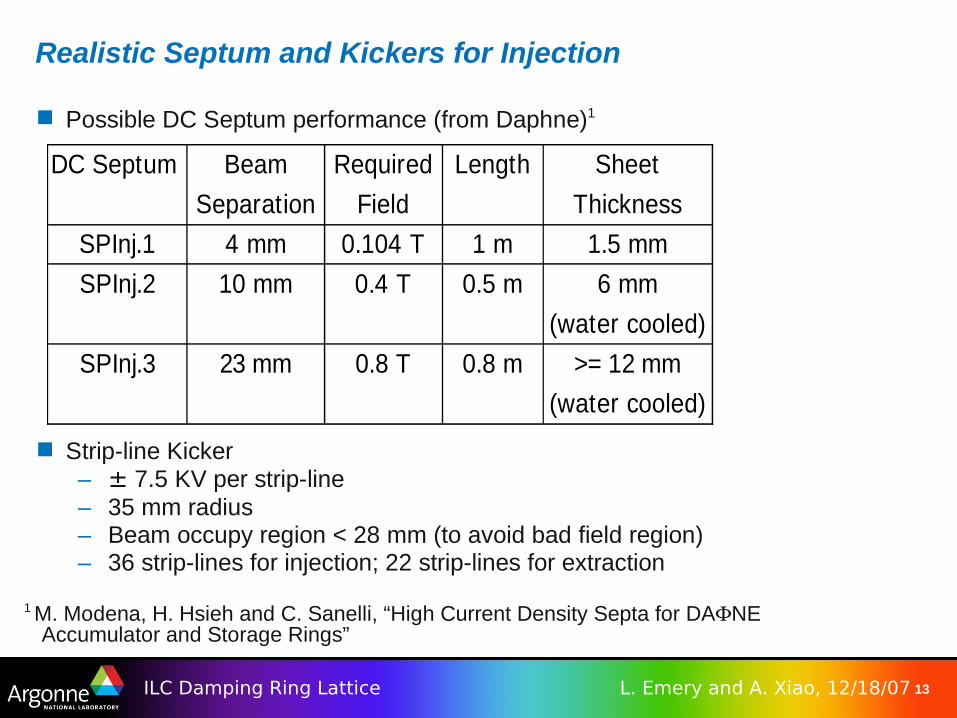
Realistic Septum and Kickers for Injection
DC Septum Beam Required Length Sheet
Separation Field Thickness
4 mm 0.104 T 1 m 1.5 mm
10 mm 0.4 T 0.5 m 6 mm
(water cooled)
23 mm 0.8 T 0.8 m >= 12 mm
(water cooled)
SPInj.1
SPInj.2
SPInj.3
Possible DC Septum performance (from Daphne)1
Strip-line Kicker– ± 7.5 KV per strip-line– 35 mm radius– Beam occupy region < 28 mm (to avoid bad field region)– 36 strip-lines for injection; 22 strip-lines for extraction
1 M. Modena, H. Hsieh and C. Sanelli, “High Current Density Septa for DANE Accumulator and Storage Rings”

14L. Emery and A. Xiao, 12/18/07ILC Damping Ring Lattice
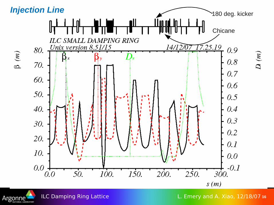
Injection Line
kickers Septum (off)
Stored-beam envelope
Beam direction

15L. Emery and A. Xiao, 12/18/07ILC Damping Ring Lattice
Injection Line Beam direction
kickers Septum (on)
16L. Emery and A. Xiao, 12/18/07ILC Damping Ring Lattice
Injection Line 180 deg. kicker
Chicane
17L. Emery and A. Xiao, 12/18/07ILC Damping Ring Lattice
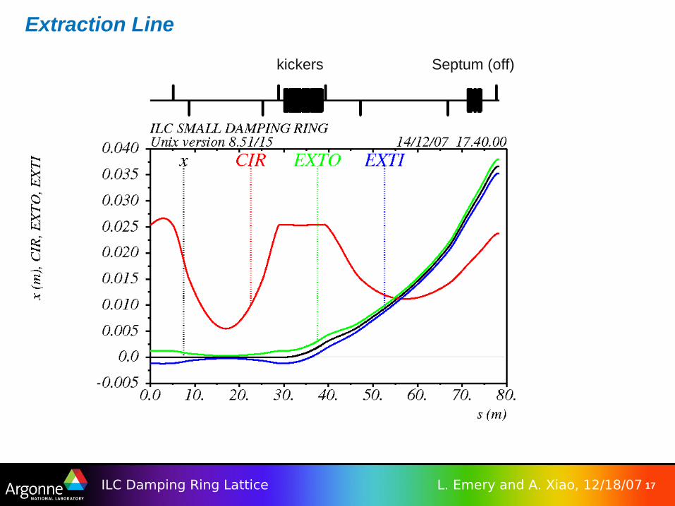
Extraction Line
kickers Septum (off)

18L. Emery and A. Xiao, 12/18/07ILC Damping Ring Lattice
Chicanes
19L. Emery and A. Xiao, 12/18/07ILC Damping Ring Lattice
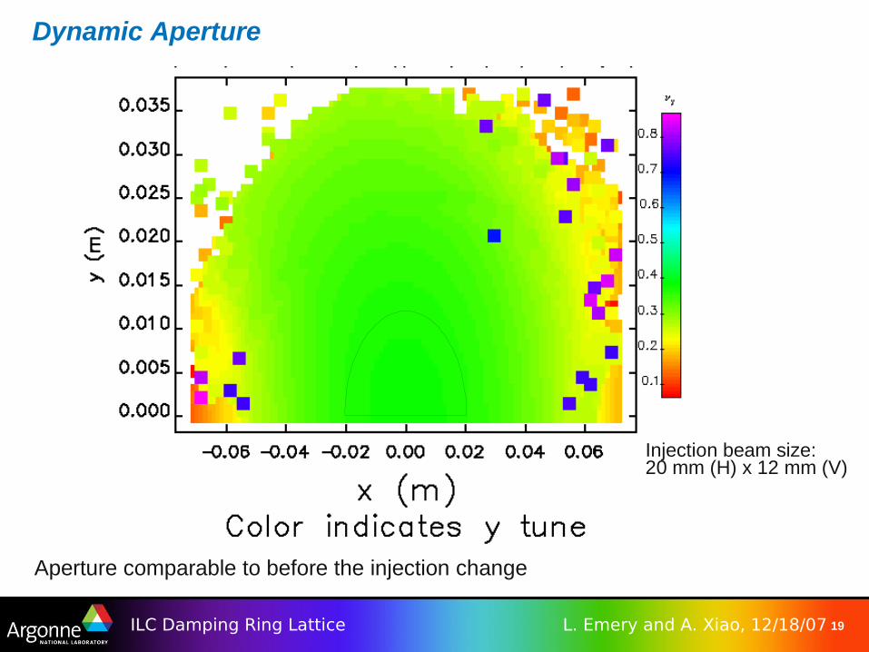
Dynamic Aperture
Aperture comparable to before the injection change
Injection beam size:20 mm (H) x 12 mm (V)
20L. Emery and A. Xiao, 12/18/07ILC Damping Ring Lattice
FODO cell Evaluation
Alternate DR with FODO cells and differently-configured straight sections Fewer quadrupoles and more dipoles Initial estimate is that DA for FODO cells in arc by itself is really no worse or
no better than TME cells– Result is that both lattices have DA that exceeds requirements
Note that original gain in DA for TME-cell is due to phase advance optimization in straight-section– May be applicable to FODO cells– Not tried with FODO cells

21L. Emery and A. Xiao, 12/18/07ILC Damping Ring Lattice
Near-Term Deliverables
Transfer lines Collimation