iki sing tak garap(2)
TRANSCRIPT
KELOMPOK 2 :
1.FAJAR MAJIDAH
2.SULUNG WISNU BRATA
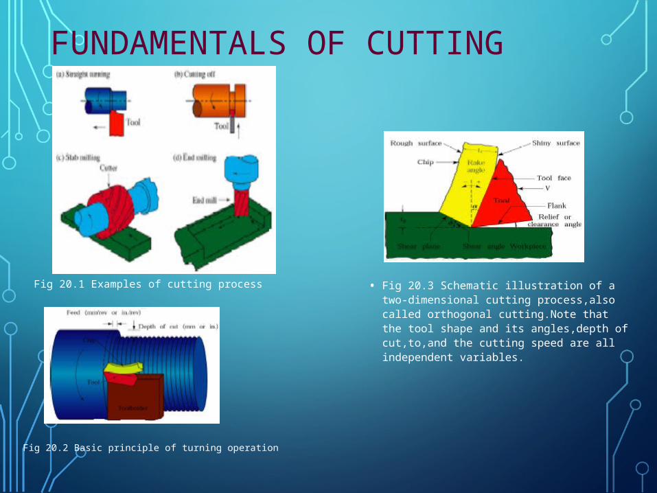
FUNDAMENTALS OF CUTTING
• Fig 20.3 Schematic illustration of a two-dimensional cutting process,also called orthogonal cutting.Note that the tool shape and its angles,depth of cut,to,and the cutting speed are all independent variables.
Fig 20.1 Examples of cutting process
Fig 20.2 Basic principle of turning operation
INTRODUCTION :•Cutting process : Remove material from the
surface of the work piece by producing chips
• Turning operation : the work piece is rotated an a cutting tool removes a layer of material as it moves to the left
•Cutting off: Cutting tool moves radially inwards and separated the right piece from the back of the blank.
• Slab-milling rotating cutting tool removes a layer of material from the surface of the work piece
• End-milling rotating cutter travels along a certain depth in the work piece and produces a cavity
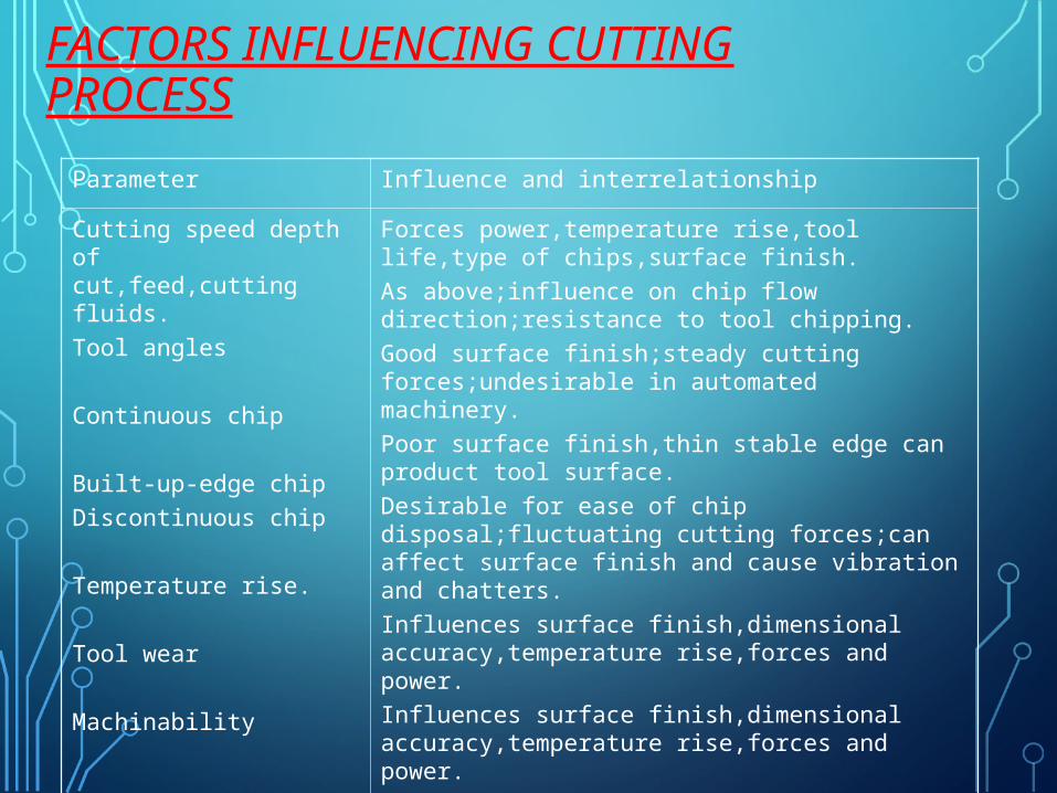
FACTORS INFLUENCING CUTTING PROCESS
Parameter Influence and interrelationship
Cutting speed depth of cut,feed,cutting fluids.
Tool angles
Continuous chip
Built-up-edge chip
Discontinuous chip
Temperature rise.
Tool wear
Machinability
Forces power,temperature rise,tool life,type of chips,surface finish.
As above;influence on chip flow direction;resistance to tool chipping.
Good surface finish;steady cutting forces;undesirable in automated machinery.
Poor surface finish,thin stable edge can product tool surface.
Desirable for ease of chip disposal;fluctuating cutting forces;can affect surface finish and cause vibration and chatters.
Influences surface finish,dimensional accuracy,temperature rise,forces and power.
Influences surface finish,dimensional accuracy,temperature rise,forces and power.
Related to tool life,surface finish,forces and power
MECHANICS OF CHIP FORMATION :
• Orthogonal cutting
• Rake angle – Alpha
• Relief angle ( clearance angle)
• Shear angle ( Pi)
• Thickness of a chip – Tc
• Depth of cut- T0
• Cutting ratio r = To / Tc
= Sin Pi / Cos ( pi- Alpha )
MECHANISM OF CHIP FORMATION
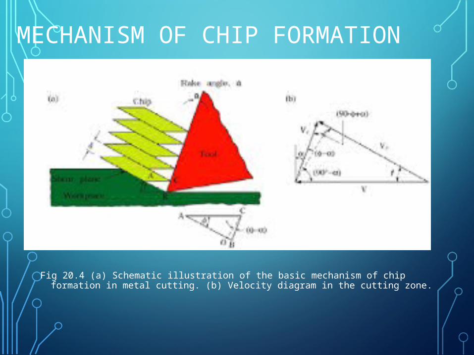
Fig 20.4 (a) Schematic illustration of the basic mechanism of chip formation in metal cutting. (b) Velocity diagram in the cutting zone.
MECHANISM OF CHIP FORMATION
• Chip compression ratio = 1 / r
• Always > unity
• On the basis of fig 20.4-a
• Shear strain gama
• Gama = AB/OC = AO/OC + OB/OC
• Gama = Cot Pi + tan ( Pi – Alpha )
• Note : for actual cutting operation shear strain > 5
MECHANISM OF CHIP FORMATION
• Shear angle adjusts itself to minimize cutting force
• Shear plane is the plane of maximum shear stress
• Pi = 45 + Alpha / 2 – Beta / 2
• Beta : Friction angle
• Mu – coefficient of friction
• Mu = tan beta
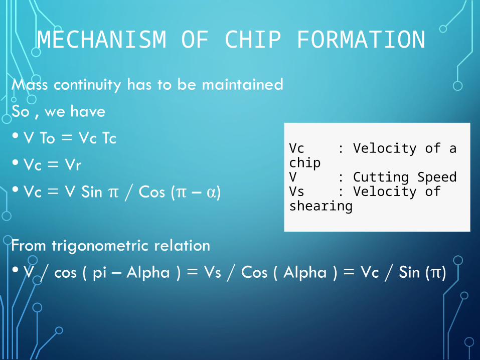
MECHANISM OF CHIP FORMATION
Vc : Velocity of a chipV : Cutting Speed Vs : Velocity of shearing
TYPES OF CHIPS
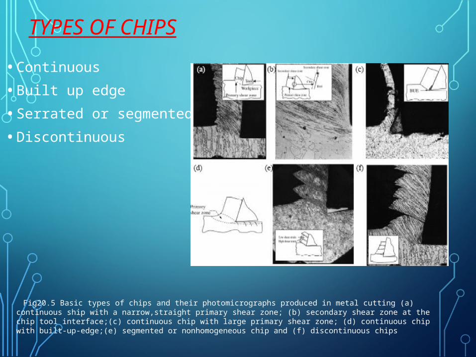
• Continuous
• Built up edge
• Serrated or segmented
• Discontinuous
Fig20.5 Basic types of chips and their photomicrographs produced in metal cutting (a) continuous ship with a narrow,straight primary shear zone; (b) secondary shear zone at the chip tool interface;(c) continuous chip with large primary shear zone; (d) continuous chip with built-up-edge;(e) segmented or nonhomogeneous chip and (f) discontinuous chips
CONTINUOUS CHIPS
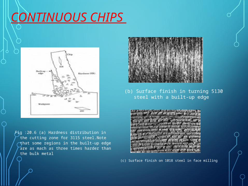
Fig :20.6 (a) Hardness distribution in the cutting zone for 3115 steel.Note that some regions in the built-up edge are as mach as three times harder than the bulk metal
(b) Surface finish in turning 5130 steel with a built-up edge
(c) Surface finish on 1018 steel in face milling
• Continuous chips are usually formed at high rake angles and/or high cutting speeds.
• A good surface finish is generally produced.
• continuous chips are not always desirable, particularly in automated machine tools,
• tend to get tangled around the tool
• operation has to be stopped to clear away the chips.
Continuous chips
BUILT-UP EDGES CHIPS• BUE consists of layers of material from the
workpiece that are gradually deposited on the tool.
• BUE then becomes unstable and eventually breaks up
• BUE material is carried away on the tool side of the chip
• the rest is deposited randomly on the workpiece surface.
• BUE results in poor surface finish
• reduced by increasing the rake angle and therefore decreasing the depth of cut.
DISCONTINUOUS CHIPS
•Discontinuous chips consist of segments that may be firmly or loosely attached to each other
• These chips occur when machining hard brittle materials such as cast iron.
• Brittle failure takes place along the shear plane before any tangible plastic flow occurs
•Discontinuous chips will form in brittle materials at low rake angles (large depths of cut).
SERRATED CHIPS
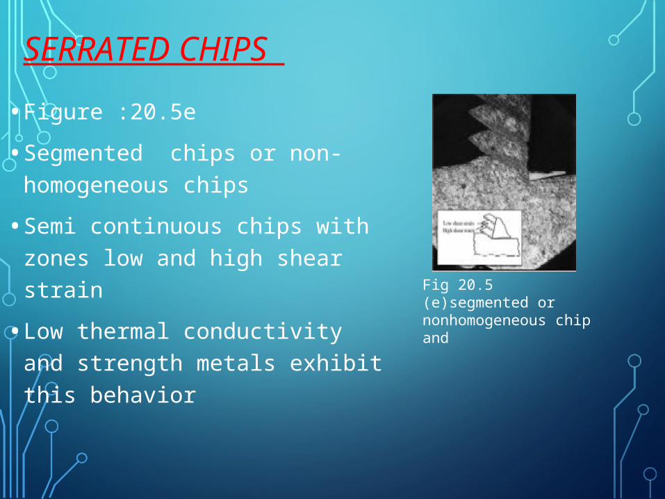
• Figure :20.5e
• Segmented chips or non-homogeneous chips
• Semi continuous chips with zones low and high shear strain
• Low thermal conductivity and strength metals exhibit this behavior
Fig 20.5 (e)segmented or nonhomogeneous chip and
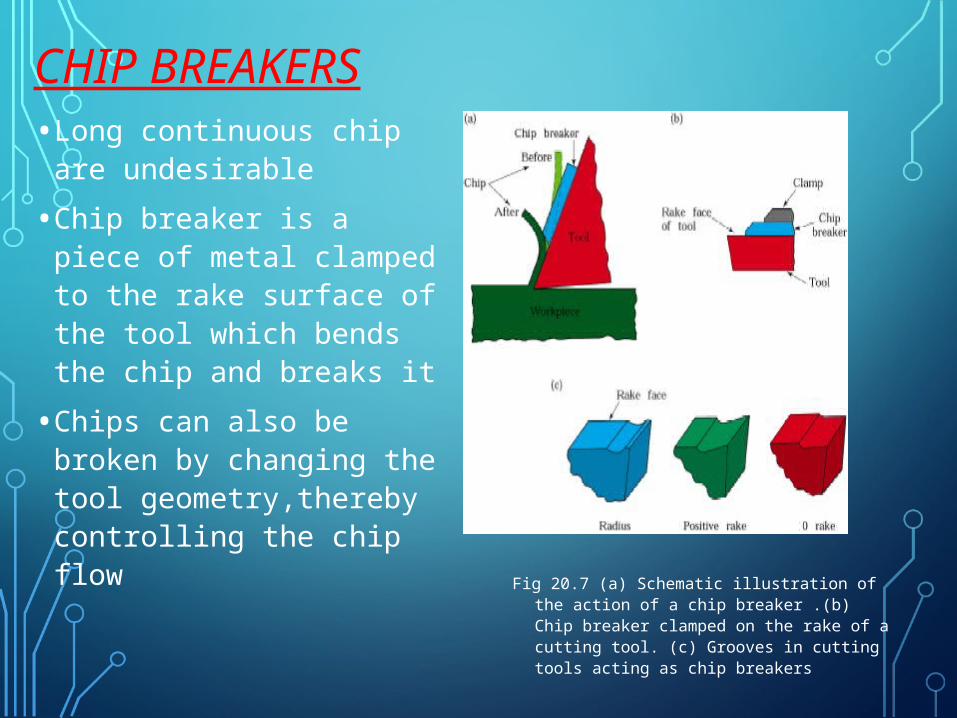
CHIP BREAKERS• Long continuous chip
are undesirable
• Chip breaker is a piece of metal clamped to the rake surface of the tool which bends the chip and breaks it
• Chips can also be broken by changing the tool geometry,thereby controlling the chip flow Fig 20.7 (a) Schematic illustration of the
action of a chip breaker .(b) Chip breaker clamped on the rake of a cutting tool. (c) Grooves in cutting tools acting as chip breakers
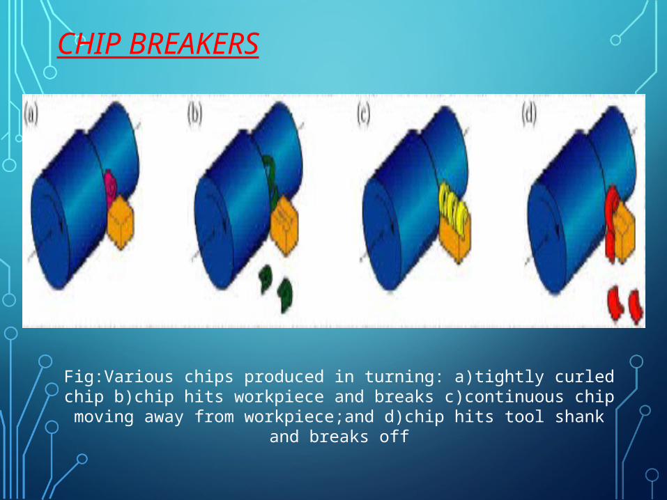
CHIP BREAKERS
Fig:Various chips produced in turning: a)tightly curled chip b)chip hits workpiece and breaks c)continuous chip moving away from workpiece;and d)chip hits tool
shank and breaks off
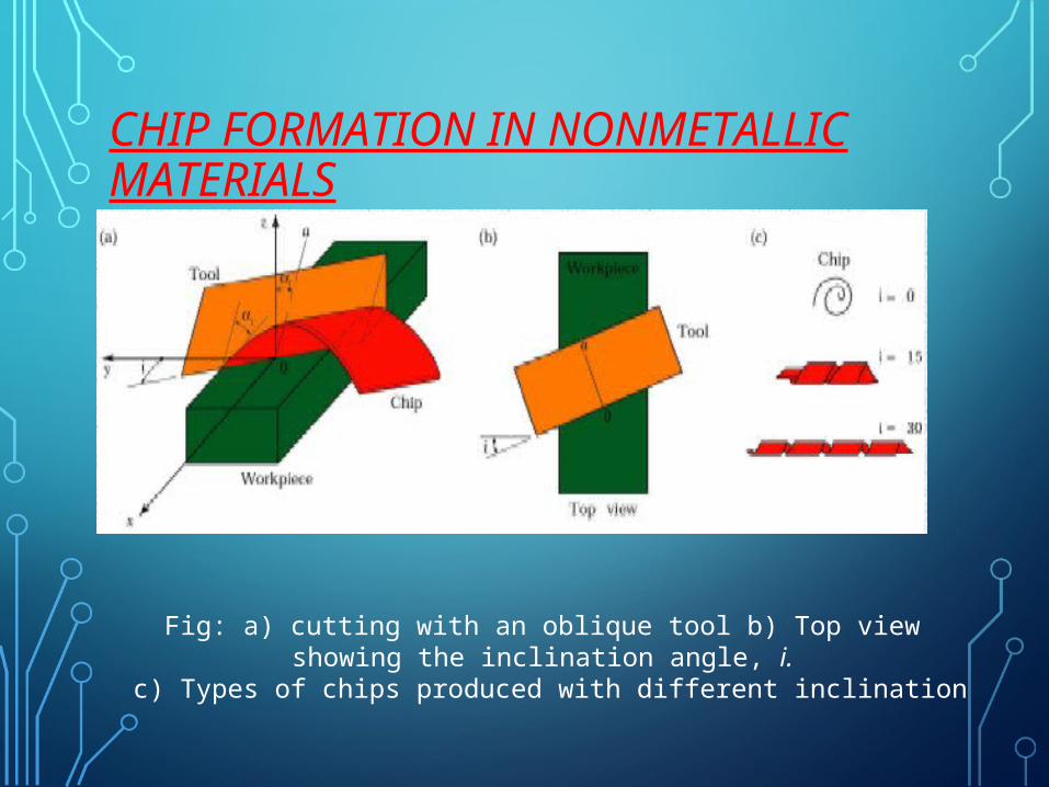
CHIP FORMATION IN NONMETALLIC MATERIALS
Fig: a) cutting with an oblique tool b) Top view showing the inclination angle, i. c) Types of chips produced with different inclination
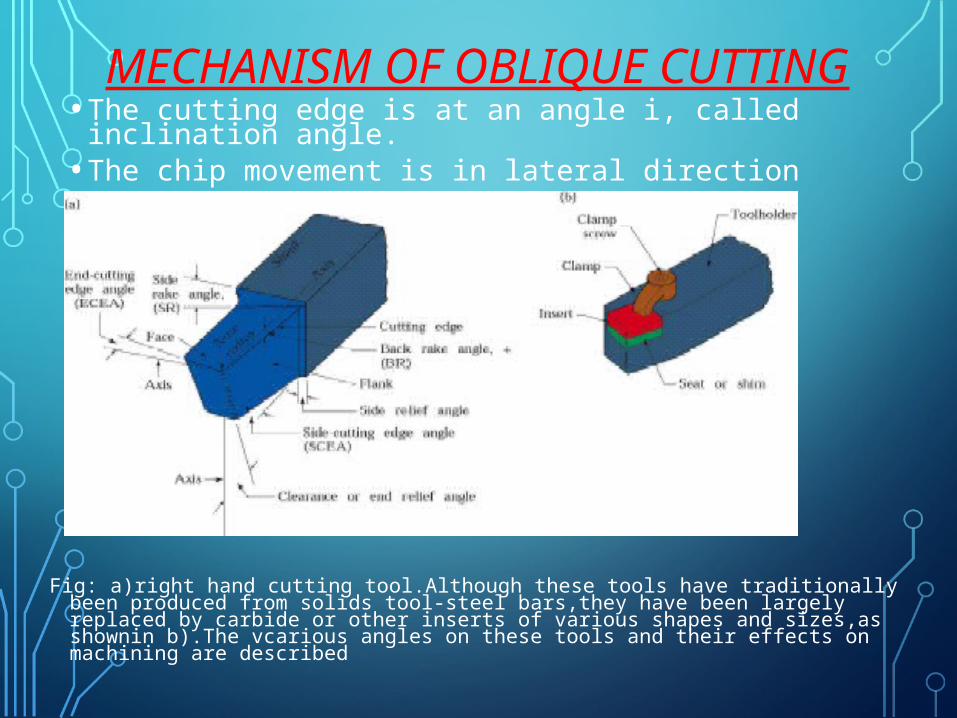
MECHANISM OF OBLIQUE CUTTING• The cutting edge is at an angle i, called inclination
angle.• The chip movement is in lateral direction
Fig: a)right hand cutting tool.Although these tools have traditionally been produced from solids tool-steel bars,they have been largely replaced by carbide or other inserts of various shapes and sizes,as shownin b).The vcarious angles on these tools and their effects on machining are described
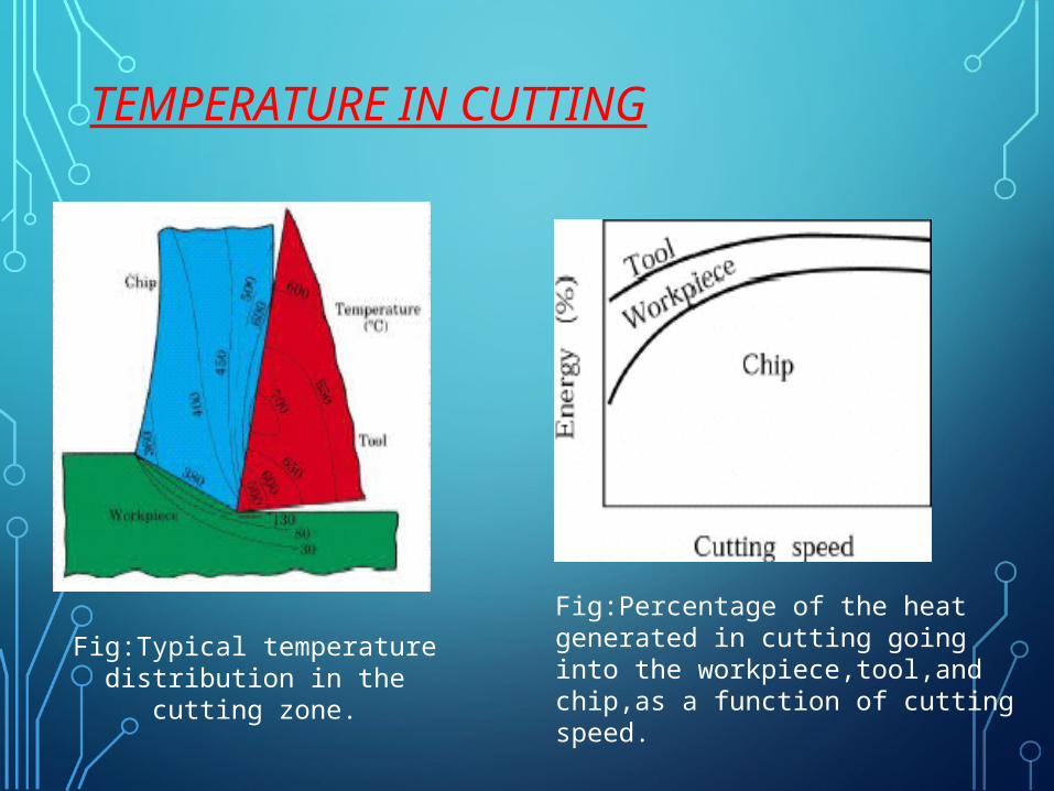
TEMPERATURE IN CUTTING
Fig:Typical temperature distribution in the cutting zone.
Fig:Percentage of the heat generated in cutting going into the workpiece,tool,and chip,as a function of cutting speed.
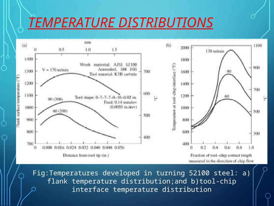
TEMPERATURE DISTRIBUTIONS
Fig:Temperatures developed in turning 52100 steel: a) flank temperature distribution;and b)tool-chip interface temperature distribution
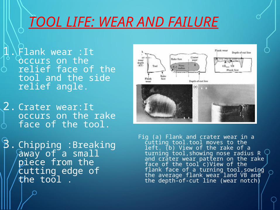
TOOL LIFE: WEAR AND FAILURE
1. Flank wear :It occurs on the relief face of the tool and the side relief angle.
2. Crater wear:It occurs on the rake face of the tool.
3. Chipping :Breaking away of a small piece from the cutting edge of the tool .
Fig (a) Flank and crater wear in a cutting tool.tool moves to the left. (b) View of the rake of a turning tool,showing nose radius R and crater wear pattern on the rake face of the tool c)View of the flank face of a turning tool,sowing the average flank wear land VB and the depth-of-cut line (wear notch)
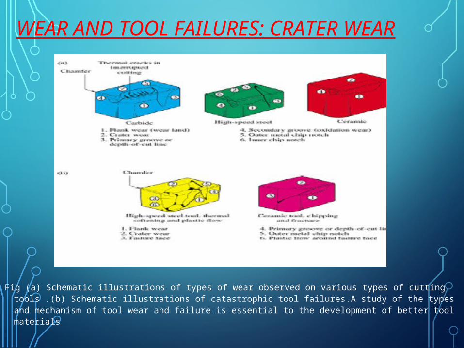
WEAR AND TOOL FAILURES: CRATER WEAR
Fig (a) Schematic illustrations of types of wear observed on various types of cutting tools .(b) Schematic illustrations of catastrophic tool failures.A study of the types and mechanism of tool wear and failure is essential to the development of better tool materials
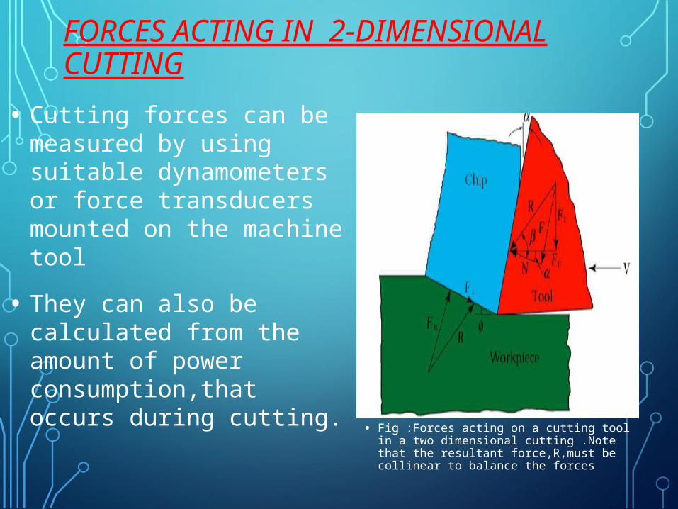
FORCES ACTING IN 2-DIMENSIONAL CUTTING
• Fig :Forces acting on a cutting tool in a two dimensional cutting .Note that the resultant force,R,must be collinear to balance the forces
• Cutting forces can be measured by using suitable dynamometers or force transducers mounted on the machine tool
• They can also be calculated from the amount of power consumption,that occurs during cutting.

THANK YOU …
THE END