iitm hpc training - indian institute of tropical...
TRANSCRIPT

IITM – HPCS Training
Day – 1
© 2013 IBM Corporation

Agenda
� Technical Infrastructure
–Cluster layout –Compute
• Sandy bridge
–Management
� Intel Cluster Studio
–Compiler• Optimization
methodology
–MPI/OpenMP• Features and
� Job Scheduler / Cluster Manager
–LSF• Basic Architecture
• Current configuration
• Scheduling policies
• Troubleshooting
© 2013 IBM Corporation
–Management • xCAT
(Provisioning tool)
–Interconnect• FDR Mellanox
–Storage• GPFS
–Software stack
• Features and
optimizations
–Math Library (MKL)–Debugging
• Parallel application
debugging
–Profiling/Tracing• VTUNE trace
analyzer
• Troubleshooting
• Profiling
• Queues and Priorities
• Fault tolerance
• Submission and
Management
–Hands On
Technical Infrastructure
© 2013 IBM Corporation
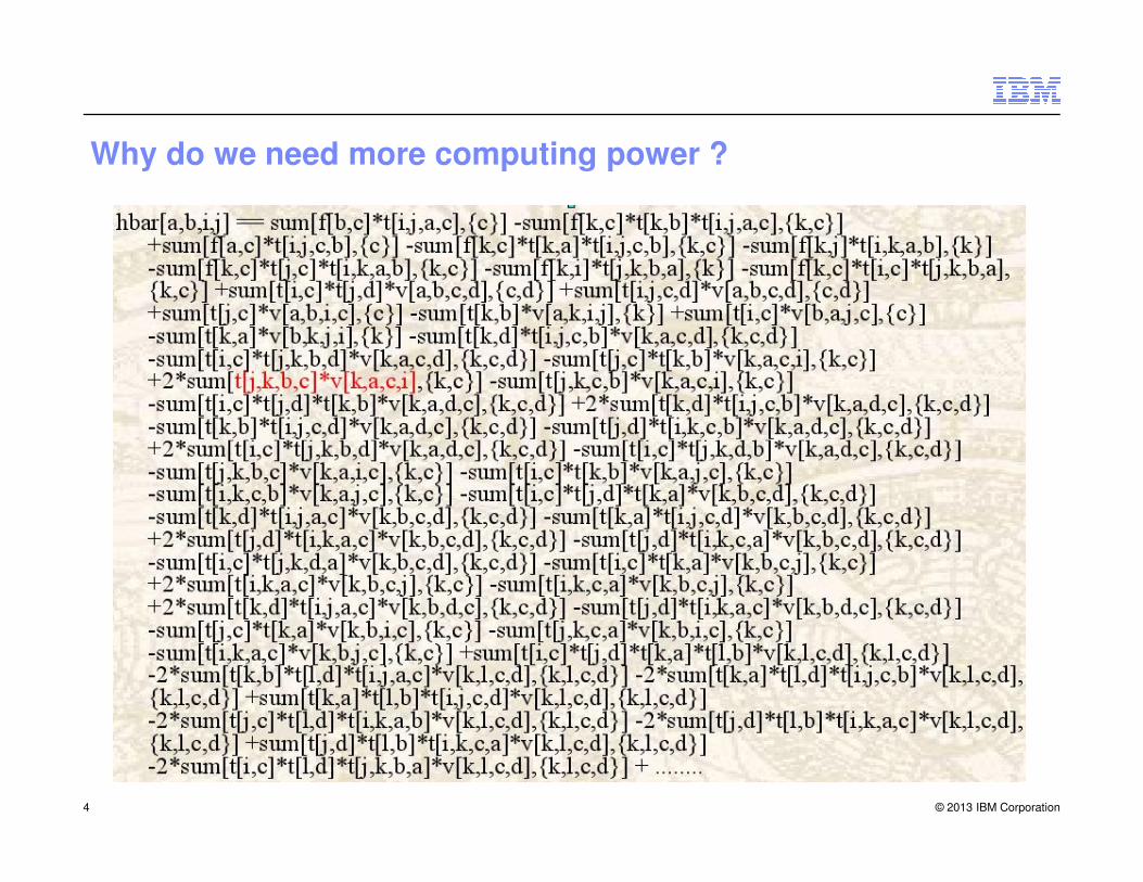
Why do we need more computing power ?
© 2013 IBM Corporation4

Seismic Analysis
Derivative Analysis
Actuarial Analysis
Mechanical/ Electric Design
Process Simulation
DrugDiscovery
Collaborative Research
Bandwidth
High Performance Computing Segments
© 2013 IBM Corporation5
Energy Finance Mfg Life Sciences Media Gov’t
Seismic Analysis
Reservoir Analysis
Asset Liability Management
Portfolio RiskAnalysis
StatisticalAnalysis
Finite Element Analysis
Failure Analysis
Protein Folding
MedicalImaging
Digital Rendering
WeatherAnalysis
High Energy Physics
Bandwidth Consumption
Gaming

Tools Compilers
Applications
Scientific Libraries Message Passing Interface
High performance computing stack
© 2013 IBM Corporation
Operating System
Parallel File System
Job Scheduler Cluster Administration
Hardware
Cluster Overview
� 800 TeraFlops High Performance Computing System IBM iDataPlex cluster, which
features 38,144 Intel Sandy Bridge processors and 149 TB of memory
� The login and compute nodes are populated with two Intel Sandy Bridge 8-core
processors.
� FDR 14 Infiniband interconnect in a Fat Tree configuration as its high-speed
network for MPI messages and IO traffic
� For High performance parallel file system we used GPFS, a most stable and higly
© 2013 IBM Corporation
� For High performance parallel file system we used GPFS, a most stable and higly
reliable for HPC clusters
� compute node has two 8-core processors (16 cores) with its own Red Hat
Enterprise Linux OS, sharing 64 GBytes of memory
� The cluster is intended to be used as a batch-scheduled jobs
� All executions that require large amounts of system resources must be sent to the
compute nodes by batch job submission through job scheduler

© 2013 IBM Corporation

© 2013 IBM Corporation

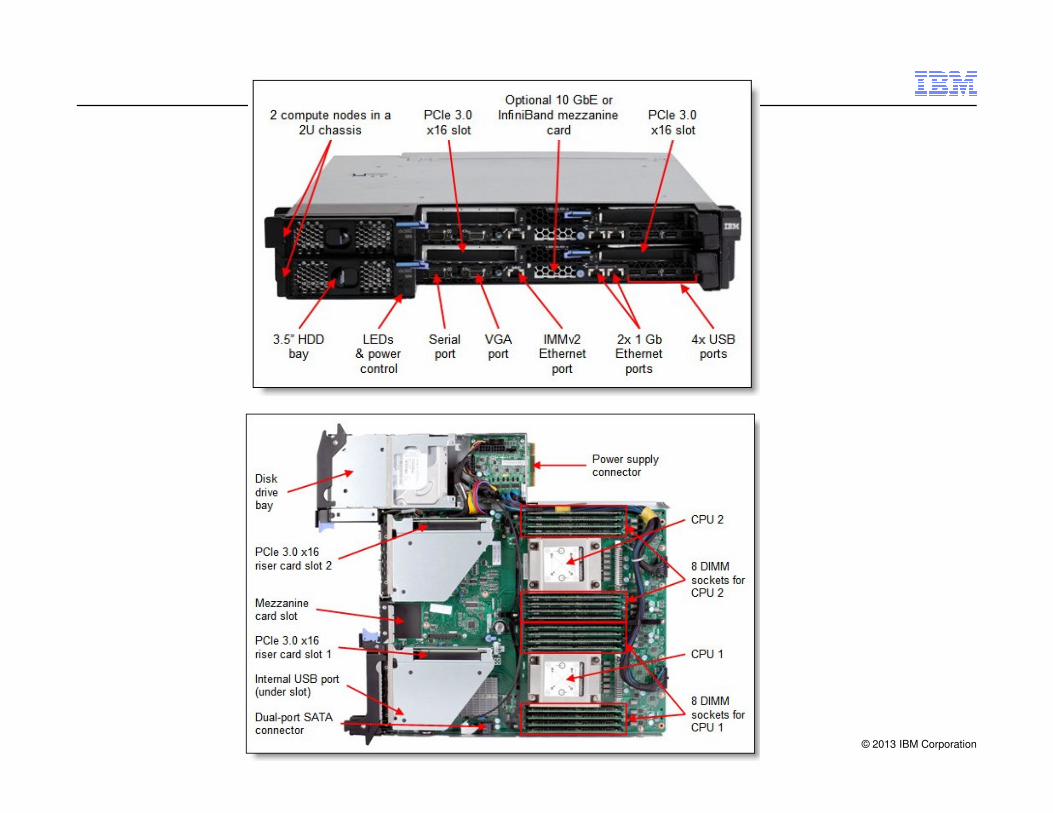
IBM System x iDataPlex Compute Building Block
� 72 x IBM System x iDataPlex dx360 M4 server
– 2x E5-2670 SandyBridge-EP 2.6GHz/1600 cache 20MB 8-core
– 8 x 8G DDR3-1600 DIMMs (4GB/core) Total: 64GB/node
– Dual-port Infiniband FDR14 Mezzazine Card
� 4 X Mellanox 36-port Managed FDR14 IB Switch
– 4 Leaf IB Switch
– 18 x compute nodes connected to each leaf switches.
– 18 Uplinks from every leaf switch connects at IB Main Switches
© 2013 IBM Corporation
– 18 Uplinks from every leaf switch connects at IB Main Switches
� Management Network
– 2 x BNT RackSwitch G8052F
– 4 x 1 Gb Connections from each switch acts as uplink for a
flawless flow of management traffic
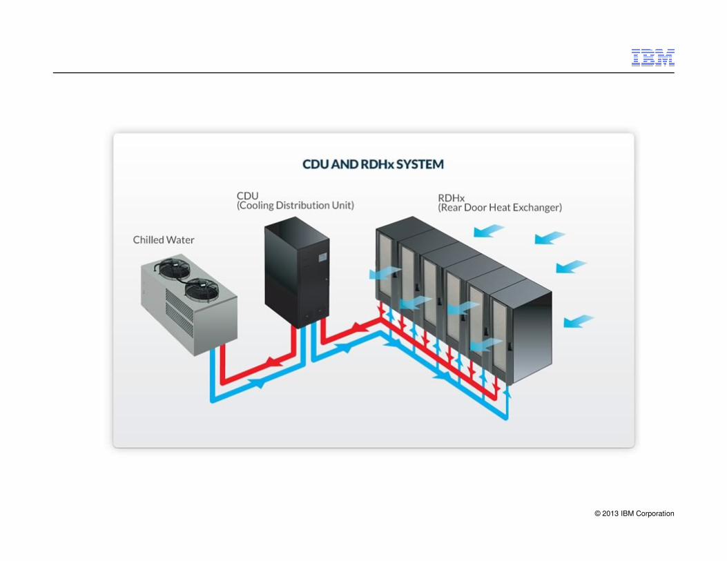
� IBM System x iDataPlex Rack with with RDHX (water cooling)
� Performance
– –2.60 GHz x 8 Flops/cycle (AVX) = 20.8 GFlops/core
– –16 core x 20.8 GFlops/core = 332.8 GFlops/node
– –72 nodes x 332.8 GFlops/node = 23.96 TFlops/rack

© 2013 IBM Corporation

© 2013 IBM Corporation

Compute
© 2013 IBM Corporation

IBM System x iDataPlex dx360 M4 Compute Node
� iDataPlex Rack server
� 1U Node Density 84 Nodes / 84U Rack
� Support SSI Planars (EP & EN)
� Shared Power –Common Form Factor (CFF)
� Shared Cooling –80mm Fans
� HPC Nodes incl 2x 1GbE down and 10GbE
© 2013 IBM Corporation
� HPC Nodes incl 2x 1GbE down and 10GbE
� 40G/QSFP IB Mezz card option
© 2013 IBM Corporation

Intel SandyBridge microprocessor
� Architecture (Tock cycle) features:
– Up to 8 cores per socket
– AVX vector units (double peak FP performance)
– Larger and faster caches
– Improved TLB ( Turbo lookaside buffer)
– Higher memory bandwidth per core
– Enhanced Turbo Mode
– Enhanced Hyper Threading mode
© 2013 IBM Corporation
– Enhanced Hyper Threading mode
– …
SandyBridge-EP model

Intel Processors Evolution
� Tock = new micro architecture
– Westmere � SandyBridge
� Tick = new manufacturing process
– (shrink of lithography)
© 2013 IBM Corporation
Sandy
Bridge EP

Intel® Core™ Microarchitecture
MeromMerom
65nm65nm
PenrynPenryn
45nm45nm
Intel® MicroarchitectureCodename Nehalem
NehalemNehalem
45nm45nm
WestmereWestmere
32nm32nm
Intel® MicroarchitectureCodename Sandy Bridge
SandySandy
BridgeBridge
32nm32nm
Ivy Ivy
BridgeBridge
22nm22nm
Intel® MicroarchitectureCodename Haswell
HaswellHaswell
22nm22nm
BroadwellBroadwell
14nm14nm
Intel Tick-Tock Development Model:Sustained Microprocessor Leadership
© 2013 IBM Corporation
TOCK
New
Micro-architecture
65nm65nm
TICK
New
Process Technology
45nm45nm
TOCK
New
Micro-architecture
45nm45nm
TICK
32nm32nm
New
Process Technology
TOCK
32nm32nm
New
Micro-architecture
TICK
22nm22nm
New
Process Technology
TOCK
22nm22nm
New
Micro-architecture
TICK
14nm14nm
New
Process Technology
18

SandyBridge-EP microprocessor
© 2013 IBM Corporation
� In addition, Sandy Bridge also introduces support for AVX (Advanced vector)extensions within an updated execution stack, enabling 256-bit floating point (FP) operations to be decoded and executed as a single micro-operation (uOp).
� The effect of this is a doubling in peak FP capability, sustaining 8 double precision FLOPs/cycle.

SandyBridge-EP microprocessor
� Sandy Bridge processor integrates a high performance, bidirectional ring architecture interconnecting
– CPU cores, Last Level Cache (LLC, or L3), PCIe, QPI, memory controller
– Able to return 32 Bytes of data on each cycle
� each physical LLC segment is loosely
© 2013 IBM Corporation
� each physical LLC segment is loosely associated with a corresponding core
– But cache is also shared among all cores as a logical unit
� The ring and LLC are clocked with the CPU core, so cache and memory
– latencies have dropped as compared to the previous generation architecture
– bandwidths are significantly improved.

Turbo Boost
� Turbo Boost– Allows dynamically increasing
CPU clock-speed on demand• « Dynamic over clocking »
– Frequency will increase in increments of 100 MHz
• When the processor has not reached its thermal and electrical limits
• When the user's workload demands additional
© 2013 IBM Corporation
demands additional performance
• Until a thermal or power limit is reachedorUntil the maximum speed for the number of active cores is reached
� Important note: – On 4 sockets systems (like x3750m4), the 2.4GHz CPU will only achieve 2.8GHz
Turbo upside on a 4S-EP (this is intentionally limited by Intel) – It is lower than the turbo upside for an equivalent 2-socket EP processor (which
would achieve 3.1GHz).
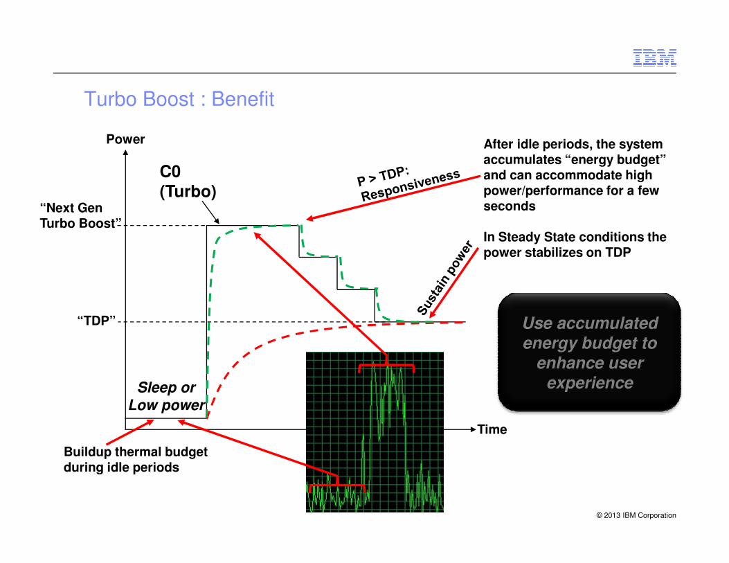
Turbo Boost : Benefit
Power
“Next Gen Turbo Boost”
C0(Turbo)
After idle periods, the system accumulates “energy budget” and can accommodate high power/performance for a few seconds
In Steady State conditions the power stabilizes on TDP
© 2013 IBM Corporation
Time
Sleep or
Low power
“TDP”
Buildup thermal budget during idle periods
Use accumulated
energy budget to
enhance user experience

FLOPS
� FLOPS (or flops or flop/s) is an acronym meaning FLoating point OPerations per Second.
� The FLOPS is a measure of a computer's performance, especially in fields of scientific calculations that make heavy use of floating point calculations.
� teraFLOPs => 10^12
© 2013 IBM Corporation23
� petaFLOPS => 10^15
� exaFLOPS => 10^18
� zettaFLOPS => 10^21

Theoretical Peak (Rpeak) vs. Sustained Peak (Rmax)
Theoretical Peak:
� Theoretical peak is the total flops which a system can perform– Let's take a system : iDataplex 2.3GHz, E5-2670V3, 2 sockets, 12 cores per socket. How do I
calculate the theoretical total flops of this box
� Flops = 24 (cores) * 2.3 (cpu clock speed) * 16 (FLOPs/cycle) = 883.2 Gflops (1 billion is 10^9 i.e. 1 gigaflops)
© 2013 IBM Corporation
� Note: 2.6GHz is 2.6 billion clock cycles per second. Haswell does 16 floating point operations for each clock cycle, whereas the previous generation Sandy bridge / Ivy bridge does 8 floating point operations for each clock cycle.
Sustained Peak:
� This is the maximal achieved performance by the system (i.e. Rmax)
24

Infiniband Interconnect
© 2013 IBM Corporation
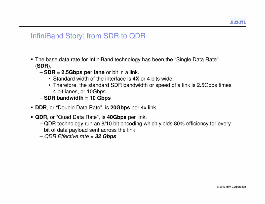
InfiniBand Story: from SDR to QDR
� The base data rate for InfiniBand technology has been the “Single Data Rate”
(SDR),
– SDR = 2.5Gbps per lane or bit in a link.
• Standard width of the interface is 4X or 4 bits wide.
• Therefore, the standard SDR bandwidth or speed of a link is 2.5Gbps times
4 bit lanes, or 10Gbps.
– SDR bandwidth = 10 Gbps
© 2013 IBM Corporation
� DDR, or “Double Data Rate”, is 20Gbps per 4x link.
� QDR, or “Quad Data Rate”, is 40Gbps per link.
– QDR technology run an 8/10 bit encoding which yields 80% efficiency for every
bit of data payload sent across the link.
– QDR Effective rate = 32 Gbps
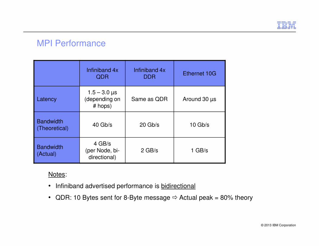
MPI Performance
Infiniband 4x QDR
Infiniband 4x DDR
Ethernet 10G
Latency1.5 – 3.0 µs
(depending on # hops)
Same as QDR Around 30 µs
Bandwidth 40 Gb/s 20 Gb/s 10 Gb/s
© 2013 IBM Corporation
Bandwidth (Theoretical)
40 Gb/s 20 Gb/s 10 Gb/s
Bandwidth (Actual)
4 GB/s(per Node, bi-
directional)2 GB/s 1 GB/s
Notes:
• Infiniband advertised performance is bidirectional
• QDR: 10 Bytes sent for 8-Byte message � Actual peak = 80% theory
Storage
© 2013 IBM Corporation
GPFS Storage server
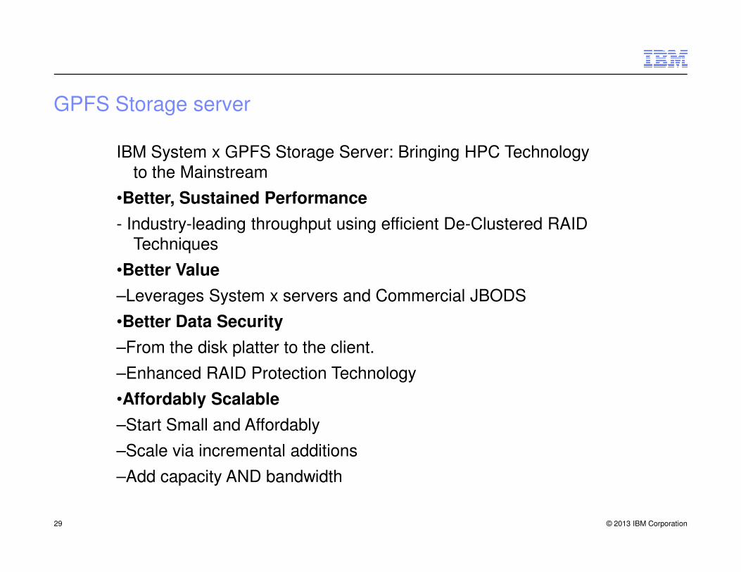
IBM System x GPFS Storage Server: Bringing HPC Technology to the Mainstream
•Better, Sustained Performance
- Industry-leading throughput using efficient De-Clustered RAID Techniques
•Better Value
–Leverages System x servers and Commercial JBODS
© 2013 IBM Corporation29
–Leverages System x servers and Commercial JBODS
•Better Data Security
–From the disk platter to the client.
–Enhanced RAID Protection Technology
•Affordably Scalable
–Start Small and Affordably
–Scale via incremental additions
–Add capacity AND bandwidth

•3 Year Warranty –Manage and budget costs •IT-Facility Friendly –Industry-standard 42u 19 inch rack mounts –No special height requirements –Client Racks are OK!
© 2013 IBM Corporation
•And all the Data Management/Life Cycle Capabilities of GPFS – Built in!
© 2013 IBM Corporation

© 2013 IBM Corporation

© 2013 IBM Corporation

© 2013 IBM Corporation
© 2013 IBM Corporation
© 2013 IBM Corporation

© 2013 IBM Corporation

General Parallel file system
© 2013 IBM Corporation

LAN
NSD ClientsMassive namespace
support
Architecture : Diagram
© 2013 IBM Corporation
SANSAN
GPFS
Seamless capacity
and performance
scaling
Centrally deployed,
managed, backed up
and grown
NSD Servers

� Optimizes storage utilization by centralizing management
� Provides a flexible scalable alternative to a growing number of NAS appliances
SAN
GPFS
© 2013 IBM Corporation
� Highly available grid computing infrastructure
� Scalable information lifecycle tools to manage growing data volumes
SAN

Parallel Filesystem
GPFS: A file system for high performance computing.as a shared disk, parallel file system for AIX, Linux clusters
Number of files:
• 2 Billion per file system
• 256 file systems
• Max File System Size: 2^99 bytes
Disk IO:
•AIX 134 GB/sec •Linux 66 GB/sec
Number of nodes:
© 2013 IBM Corporation41
Software features: snapshots, replication and multi-site connectivity are included in the GPFS license. There are no license keys besides client and server to add-on, you get all of the features up front.
• Max File System Size: 2^99 bytes
• Max File Size = File system size
Number of nodes:
• 1 to 8192

• GPFS 2.3, or later, architectural file system size limit
– 2^99 bytes
– Current tested limit ~2 PB
• Total number of files per file system
– 4,000,000,000 (four billion - GPFS 3.4 created file system, two billion on 3.2 or earlier
GPFS versions)
• Total number of nodes: 8,192
– A node is in a cluster if:
Architecture Stat
© 2013 IBM Corporation
– A node is in a cluster if:
• The node shows in mmlscluster (shows up in mmlscluster) or
• The node is in a remote cluster and is mounting a file system in the local cluster
• Maximum number of mounted file systems
– 256
– Before GPFS 3.2, 64 file systems
• Maximum disk size
– Limited by disk device driver and O/S

GPFS provides a highly scalable file management infrastructure
� Optimizes storage utilization by centralizing management
� Provides a flexible scalable alternative to a growing number of NAS appliances
What GPFS provides
© 2013 IBM Corporation
NAS appliances
� Highly available grid computing infrastructure
� Scalable information lifecycle tools to manage growing data volumes

Internal design
© 2013 IBM Corporation
• The GPFS kernel extension provides:
– Interfaces to the operating system vnode and VFS.
• Flow:
– Application makes file system calls to the O/S.
– O/S presents calls to the GPFS kernel extension.
• GPFS appears to the application as just another file system.
– GPFS kernel extension will either satisfy requests using information already available
or send a message to the GPFS daemon to complete the request.
Kernel Extension
© 2013 IBM Corporation
or send a message to the GPFS daemon to complete the request.
– The GPFS daemon
• It performs all I/O and buffer management, including read ahead for sequential reads
and write behind operations.
• All I/O is protected by token management to ensure file system consistency.
• Multi-threaded with some threads dedicated to specific functions.
– Examples include space allocation, directory management (insert and removal), and
quotas.
• Disk I/O is initiated on threads of the daemon.

Manager nodes
• Global lock manager
• File system configuration: recovery, adding disks, …
• Disk space allocation manager
• Quota manager
• File metadata manager - maintains file metadata integrity
Node Roles
© 2013 IBM Corporation
File system nodes
• Run user programs, read/write data to/from storage nodes
• Implement virtual file system interface
• Cooperate with manager nodes to perform metadata operations
Storage nodes
• Implement block I/O interface
• Shared access to file system and manager nodes
• Interact with manager nodes for recovery

ILM tools� Storage pools
– A collection of disks or arrays with similar properties that are managed together as a group.
� File placement policies– Determines where the file data is
placed on creation.
� File management policies– Migrates or deletes file based on
business rules
Storage
Pool
Storage
PlacementPolicies
Filesets
© 2013 IBM Corporation© Copyright IBM Corporation 2010, 2013. All Rights Reserved.
business rules
� Filesets– Logical subtrees within a file system
that act as metadata containers for files.
Storage
Pool
Storage
Pool
ManagementPolicies

What is a storage pool?
� Two types of storage pools
– Internal
– External
� Internal: A collection of disks or arrays with similar properties that are managed
together as a group.
– Group storage devices and create classes of storage within a file system
– Match the cost of storage to the value of the data
– Improved performance
© 2013 IBM Corporation© Copyright IBM Corporation 2010, 2013. All Rights Reserved.
– Improved performance
– Improved reliability
� External
– An interface to an external application

What are filesets?
� A fileset is a sub-tree of a file system namespace that provides a means of
partitioning the file system to allow administrative operations.
– In many ways behaves like an independent file system
– Used to define quotas on data blocks and inodes
� A fileset has a root directory.
– All files belonging to the fileset are only accessible through this root directory
– No hard links between filesets are allowed
– Renames are not allowed to cross fileset boundaries
© 2013 IBM Corporation© Copyright IBM Corporation 2010, 2013. All Rights Reserved.
– Renames are not allowed to cross fileset boundaries
Policy-based management
� Two types of policies
– File placement
– File management
� File placement policies
• Determine the initial storage pool for each file’s data
►The data will be striped across all disks in the selected pool
• Also determines the file’s replication factor
© 2013 IBM Corporation© Copyright IBM Corporation 2010, 2013. All Rights Reserved.
� File management policies
• Determines when a file’s data should be migrated
• Determines where the data should go
Policy rules
� Similar syntax to SQL 92 standard
� You can have 1 MB of rule text
� Rule order matters
– Rules are evaluated top to bottom
– Once a rule matches processing ends for that file
� You can use built-in functions. Examples: – Date: Current_Timestamp, DayOfWeek, DAY(), HOUR()
© 2013 IBM Corporation© Copyright IBM Corporation 2010, 2013. All Rights Reserved.
– Date: Current_Timestamp, DayOfWeek, DAY(), HOUR()
– String: LOWER(), UPPER(),LENGTH()
– Numeric: INT(), MOD()

Rule syntax: Placement policy
� SyntaxRULE ['RuleName']
SET POOL 'PoolName'
[LIMIT (OccupancyPercentage)]
[REPLICATE (DataReplication)]
[FOR FILESET (FilesetName[,FilesetName]...)]
[WHERE SqlExpression]
� Can be set on attributes you know about a file when it is created
© 2013 IBM Corporation© Copyright IBM Corporation 2010, 2013. All Rights Reserved.
� Can be set on attributes you know about a file when it is created
– Name, location, user

File management policy processing� Batch process
� Very efficient metadata scans
� When a batch is executed there are three
steps:
– Directory scan
– Rule evaluation
– File operations
� Can operate in parallel over multiple
Scan Files
1
Apply Rules2
© 2013 IBM Corporation© Copyright IBM Corporation 2010, 2013. All Rights Reserved.
� Can operate in parallel over multiple
machines Apply Rules2
Perform File Operations
3

High availability
� Infrastructure– Storage– SAN– Networking– Server HW
© 2013 IBM Corporation© Copyright IBM Corporation 2010, 2013. All Rights Reserved.
� GPFS– Node location– Quorum – Replication– Multi-site

Replication examples
� Full replication– Two failure groups
– Data and metadata
– On failure file system all ok
� Metadata Replication– Replicate only metadata
– On failure data missing file
system stays mounted
Failure Group 1
Failure Group 1
inode
Metadata OK
© 2013 IBM Corporation© Copyright IBM Corporation 2010, 2013. All Rights Reserved.
Failure Group 1
Failure Group 2
Failure Group 2
Failure Group 3
Failure Group 4
inode
Missing Data
Failure Group 3 (Desc Only)
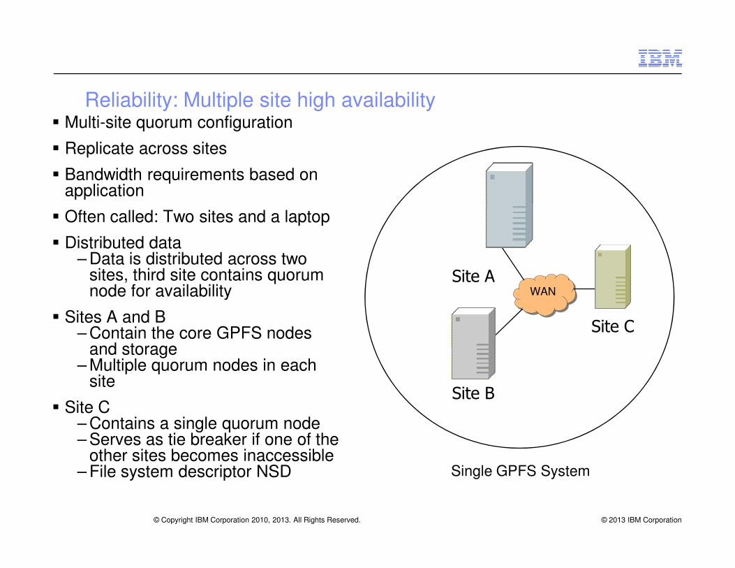
Reliability: Multiple site high availability� Multi-site quorum configuration
� Replicate across sites
� Bandwidth requirements based on application
� Often called: Two sites and a laptop
� Distributed data– Data is distributed across two
sites, third site contains quorum node for availability
Site A
© 2013 IBM Corporation© Copyright IBM Corporation 2010, 2013. All Rights Reserved.
node for availability
� Sites A and B – Contain the core GPFS nodes
and storage– Multiple quorum nodes in each
site
� Site C – Contains a single quorum node– Serves as tie breaker if one of the
other sites becomes inaccessible – File system descriptor NSD Single GPFS System
Site A
Site B
Site C
WAN

� Use mmdelnode to remove a node from a cluster:mmdelnode { -a | -N Node[,Node…] |
NodeFile|NodeClass]
–Cannot be primary or secondary GPFS cluster configuration node (unless removing entire cluster)
–Cannot be an NSD server (unless removing entire cluster) –Can be run from any node remaining in the GPFS cluster
Adminitration : Node Deletion
© 2013 IBM Corporation
–Can be run from any node remaining in the GPFS cluster–GFPS daemon must be stopped on node being deleted
� Deleting some nodes:–Avoid unexpected consequences due to quorum loss
� Deleting a cluster using the mmdelnode command:mmdelnode -a
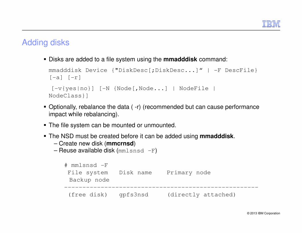
� Disks are added to a file system using the mmadddisk command:
mmadddisk Device {"DiskDesc[;DiskDesc...]“ | -F DescFile}
[-a] [-r]
[-v{yes|no}] [-N {Node[,Node...] | NodeFile |
NodeClass}]
� Optionally, rebalance the data ( -r) (recommended but can cause performance
impact while rebalancing).
Adding disks
© 2013 IBM Corporation
impact while rebalancing).
� The file system can be mounted or unmounted.
� The NSD must be created before it can be added using mmadddisk.
– Create new disk (mmcrnsd)– Reuse available disk (mmlsnsd –F)
# mmlsnsd -F
File system Disk name Primary node
Backup node
-----------------------------------------------------
(free disk) gpfs3nsd (directly attached)

� Managing disks within a file system
– Disk errors
– Performance evaluation
– Planning for migration
� Modify disk state using the mmchdisk command# mmchdisk
Usage:
mmchdisk Device {resume | start} -a
Changing disk attributes
© 2013 IBM Corporation
mmchdisk Device {resume | start} -a
[-N {Node[,Node...] | NodeFile |
NodeClass}]
or
mmchdisk Device {suspend | resume | stop | start |
change}
{-d "DiskDesc[;DiskDesc...]" | -F DescFile}
[-N {Node[,Node...] | NodeFile |
NodeClass}]
� Example
– Restart disk after fixing storage failure

� A disk can be replaced by a new disk.– Need a free NSD as large or larger than original– Cannot replace stopped disk– Cannot replace disk if only disk in file system– Do not need to unmount file system– No need to re-stripe– File system can be mounted or unmounted
Replacing Disks
© 2013 IBM Corporation
� It is replaced using the mmrpldisk command.
� Usage:mmrpldisk Device DiskName {DiskDesc | -F DescFile}
[-v {yes | no}]
[-N {Node[,Node...] | NodeFile
| NodeClass}]

� Disks are removed from a file system using the mmldedisk command.– Migrates data to remaining disks in file system– Removes disk from file system descriptor– Can be run from any node in cluster
� The mmdeldisk command:– Usage:
mmdeldisk Device {"DiskName[;DiskName...]" | -F
DiskFile} [-a] [-c]
[-r] [-N {Node[,Node...] | NodeFile |
NodeClass}]
Deleting a Disk
© 2013 IBM Corporation
NodeClass}]
� Usage scenarios:– If disk is not failing and still readable by GPFS:
• Suspend the disk (mmchdisk disk_name suspend).• Re-stripe to rebalance all data onto other disks (mmrestripefs –b).• Delete the disk (mmdeldisk).
� If disk is permanently damaged and file system is replicated:– Suspend and stop disk (mmchdisk disk_name suspend; mmchdisk disk_name stop)
– Re-stripe and restore replication for the file system, if possible (mmrestripefs –r)
– Delete the disk from the file system (mmdeldisk)

� mmchfs command
– Usage:mmchfs Device [-A {yes | no | automount}] [-D {posix |
nfs4}] [-E {yes | no}]
[-F
MaxNumInodes[:NumInodesToPreallocate]]
[-k {posix | nfs4 | all}] [-K {no |
whenpossible | always}]
[-m DefaultMetadataReplicas] [-o
File system
© 2013 IBM Corporation
[-m DefaultMetadataReplicas] [-o
MountOptions]
[-Q {yes | no}] [-r
DefaultDataReplicas] [-S {yes | no}]
[-T Mountpoint] [-t DriveLetter] [-V
{full | compat}] [-z {yes | no}]
ormmchfs Device -W NewDeviceName
� Cannot modify
– Blocksize
– Logfile (-L LogFileSize in mmcrfs)
– MaxDataReplicas and MaxMetadataReplicas
– numnodes

� Quotas are set using the mmedquota command.
� Issue mmedquota to explicitly set quotas for a user, groups, or filesets.mmedquota {-u [-p ProtoUser] User... |
-g [-p ProtoGroup] Group... |
-j [-p ProtoFileset] Fileset... |
-d {-u User... | -g Group... | -j Fileset}
|
-t {-u | -g | -j}}
– Confirm using mmrepquota command.
Setting up user quota
© 2013 IBM Corporation
– Confirm using mmrepquota command.
� Example: Edit quota for user user1# mmedquota –u user1
*** Edit quota limits for USR tests
NOTE: block limits will be rounded up to the next
multiple of the block size.
block units may be: K, M, or G.
fs1: blocks in use: 0K, limits (soft = 0K, hard = 0K)
inodes in use: 0, limits (soft = 0, hard = 0)
RDHX
© 2013 IBM Corporation
© 2013 IBM Corporation

Cluster management
© 2013 IBM Corporation
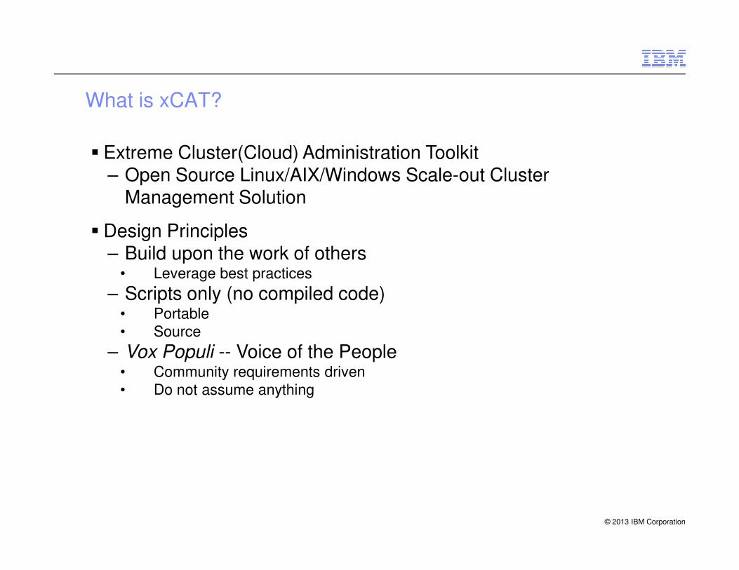
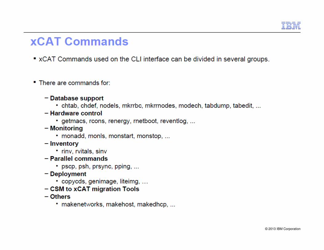
What is xCAT?
� Extreme Cluster(Cloud) Administration Toolkit– Open Source Linux/AIX/Windows Scale-out Cluster
Management Solution
� Design Principles– Build upon the work of others
• Leverage best practices
– Scripts only (no compiled code)
© 2013 IBM Corporation
– Scripts only (no compiled code)• Portable
• Source
– Vox Populi -- Voice of the People• Community requirements driven
• Do not assume anything

What does xCAT do?
� Remote Hardware Control– Power, Reset, Vitals, Inventory, Event Logs, SNMP alert processing– xCAT can even tell you which light path LEDs are lit up remotely
� Remote Console Management– Serial Console, SOL, Logging / Video Console (no logging)
� Remote Destiny Control– Local/SAN Boot, Network Boot, iSCSI Boot
� Remote Automated Unattended Network Installation
© 2013 IBM Corporation
� Remote Automated Unattended Network Installation– Auto-Discovery
• MAC Address Collection• Service Processor Programming• Remote Flashing
– Kickstart, Autoyast, Imaging, Stateless/Diskless, iSCSI
� Scales! Think 100,000 nodes.
� xCAT will make you lazy. No need to walk to datacenter again.

Functionality
� Remote Hardware Control
– Power, reset, vitals, inventory, event logs, SNMP alert processing
� Remote Console Management
– Serial console, SOL, logging
� Remote Destiny Control
– Local boot, network boot, iSCSI boot
� Parallel Cluster control
© 2013 IBM Corporation
� Parallel Cluster control
– parallel shell, parallel rsync, parallel secure copy, parallel ping
� Remote Automated Unattended Network Installation
– Auto-discovery
• MAC address collection
• Service processor programming
– Remote flashing
– Kickstart, Autoyast, imaging, stateless/diskless
� Easy to Use and it Scales! Think 100000 nodes
– xCAT will make you lazy - no need to walk to datacenter again
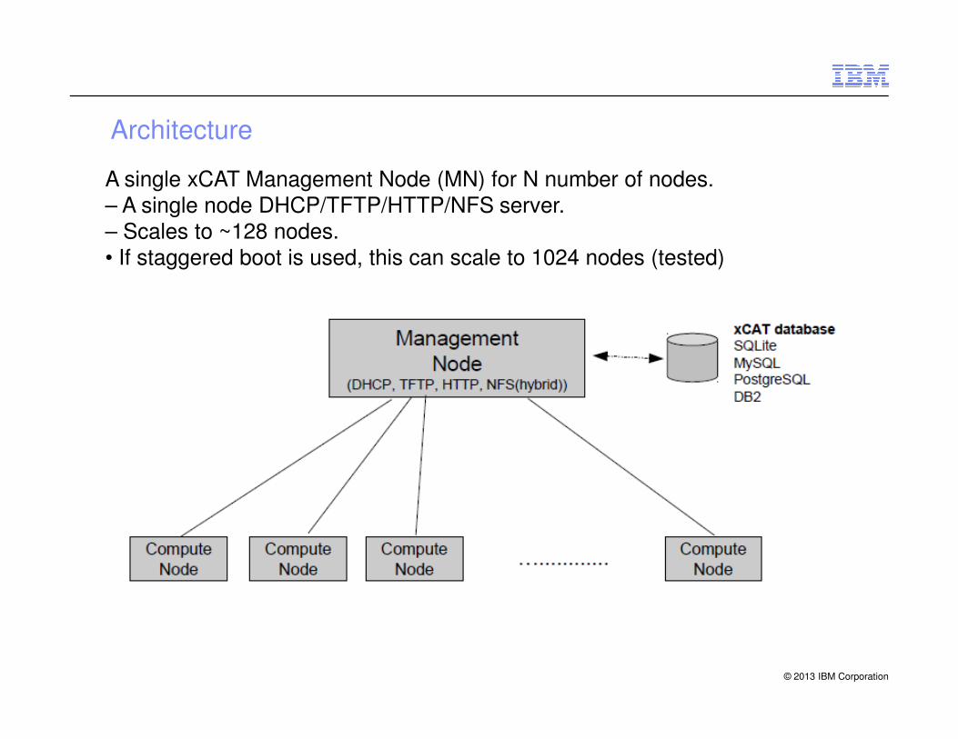
Architecture
A single xCAT Management Node (MN) for N number of nodes.– A single node DHCP/TFTP/HTTP/NFS server.– Scales to ~128 nodes.• If staggered boot is used, this can scale to 1024 nodes (tested)
© 2013 IBM Corporation

Scale Infrastructure
� A single xCAT management node with multiple service nodes providing boot services to increasing scaling.
� Can scale to 1000s and 10000s of nodes.
� xCAT already provides this support for large diskfull clusters and it can by applied to stateless as well.
� The number of nodes and network infrastructure will determine the number of DHCP/TFTP/HTTP servers required for a parallel reboot with no DHCP/TFTP/HTTP timeouts.
� The number of DHCP servers does not need to equal the number of TFTP or HTTP servers. TFTP servers NFS mount read-only the /tftpboot and image directories from the
© 2013 IBM Corporation
servers. TFTP servers NFS mount read-only the /tftpboot and image directories from the management node to provide a consistent set of kernel, initrd, and file system images.
node001 node002 ... nodennn
DHCP TFTP HTTP NFS(hybrid)
DHCP TFTP HTTP NFS(hybrid)
nodennn + 1 nodennn + 2 ... nodennn + m
DHCP TFTP HTTP NFS(hybrid)
...
IMNmgmt node
service node01 service node02 service nodeNN
IMN...
Tables and Database
� xCAT stores all information about the nodes and subsystems it manages in a
database.
– XCAT default database is located in /etc/xcat in sqlite tables. XCAT can be
instructed to store the tables in MySQL, PostgreSQL or DB2 as well.
� For most installations you won't need to even fill up half of the tables!
– And for the tables that you do need, in most cases you'll only need to put one
line in the table!
� There are lot of tables but only some tables are for common to Linux and AIX, some
© 2013 IBM Corporation
� There are lot of tables but only some tables are for common to Linux and AIX, some
are for only AIX, some just for monitoring, some for advanced functions (virtual
machines, iSCSI settings), …
� xCAT comes with a rich set of functions for manipulating tables.
© 2013 IBM Corporation

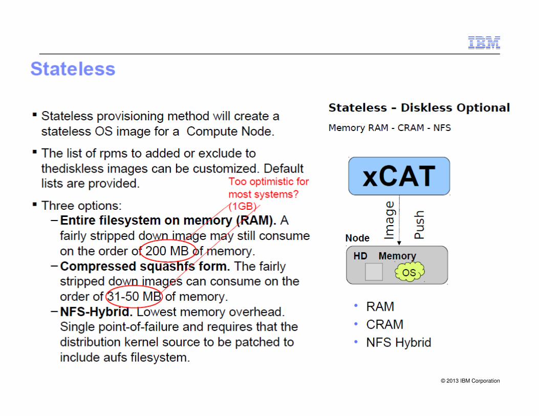
Provisioning methods
xCAT
Stateful –
Diskful
Local - HD - Flash
Stateful –
Disk-Elsewhere
San - iSCSi
Stateless –
Disk Optional
Memory RAM - CRAM - NFS
xCAT xCAT
OS
In
sta
lle
r
OS
In
sta
lle
r
Ima
ge
Pu
sh
© 2013 IBM Corporation
HD Memory
Node
OS
In
sta
lle
r
HD Memory HD Memory
SAN/iSCSI/NAS
OS
In
sta
lle
r
Ima
ge
Pu
sh
Node Node
OS
OS
• HD
• Flash
• RAM
• CRAM
OS
Statelite
© 2013 IBM Corporation

© 2013 IBM Corporation
© 2013 IBM Corporation

Management &Monitoring
© 2013 IBM Corporation
Big Endian vs. Little Endian
© 2013 IBM Corporation

Byte Addressability
� Bytes are always 8 bits
� Word length typically ranges from 16 to 64 bits.
� Memory location assignments refer to successive byte locations in memory
• Memory is byte-accessible.
� For 8086, a Word is 16-bits (2 bytes)
© 2013 IBM Corporation

Data Type - C
Type Storage size Value range
char 1 byte -128 to 127 or 0 to 255
unsigned char 1 byte 0 to 255
signed char 1 byte -128 to 127
© 2013 IBM Corporation
signed char 1 byte -128 to 127
int 2 or 4 bytes-32,768 to 32,767 or -2,147,483,648 to 2,147,483,647
unsigned int 2 or 4 bytes0 to 65,535 or 0 to 4,294,967,295
short 2 bytes -32,768 to 32,767
unsigned short 2 bytes 0 to 65,535
long 4 bytes-2,147,483,648 to 2,147,483,647
unsigned long 4 bytes 0 to 4,294,967,295
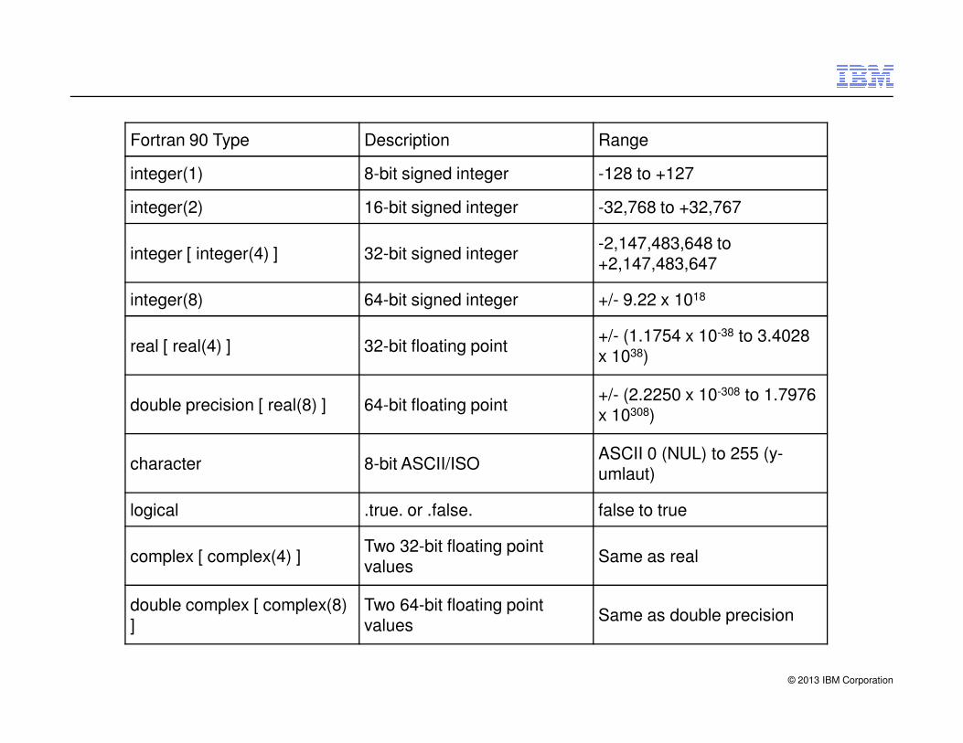
Fortran 90 Type Description Range
integer(1) 8-bit signed integer -128 to +127
integer(2) 16-bit signed integer -32,768 to +32,767
integer [ integer(4) ] 32-bit signed integer-2,147,483,648 to +2,147,483,647
integer(8) 64-bit signed integer +/- 9.22 x 10¹⁸
real [ real(4) ] 32-bit floating point+/- (1.1754 x 10-38 to 3.4028 x 1038)
© 2013 IBM Corporation
double precision [ real(8) ] 64-bit floating point+/- (2.2250 x 10-308 to 1.7976 x 10308)
character 8-bit ASCII/ISOASCII 0 (NUL) to 255 (y-umlaut)
logical .true. or .false. false to true
complex [ complex(4) ]Two 32-bit floating point values
Same as real
double complex [ complex(8) ]
Two 64-bit floating point values
Same as double precision

Word Length
�For the 8086, a Word is 16-bits (2 bytes)
© 2013 IBM Corporation
A Signed Integer
b15 b14 … … … … b1 b0
<------------------------------16 bits ----------------------------->
2 Characters
8 bits 8 bits
<----- ASCII character -----> <----- ASCII character ----->
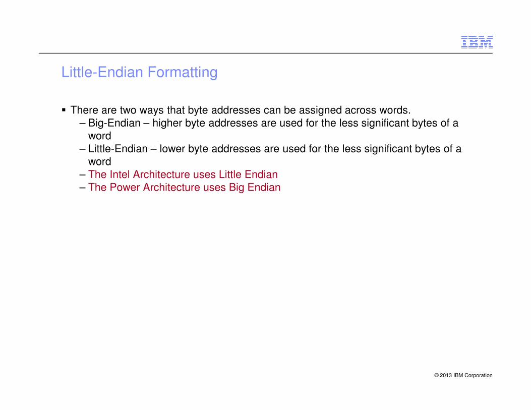
Little-Endian Formatting
� There are two ways that byte addresses can be assigned across words.
– Big-Endian – higher byte addresses are used for the less significant bytes of a
word
– Little-Endian – lower byte addresses are used for the less significant bytes of a
word
– The Intel Architecture uses Little Endian
– The Power Architecture uses Big Endian
© 2013 IBM Corporation

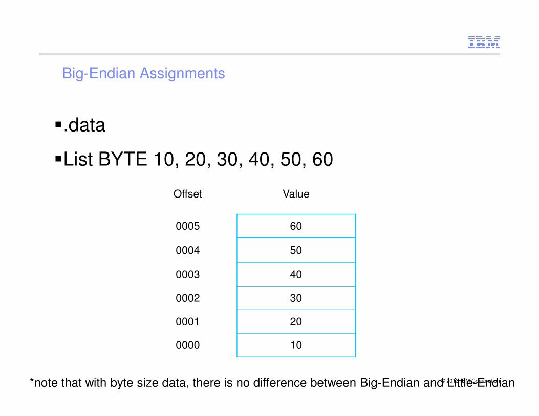
Little-Endian Assignments
�.data
�List BYTE 10, 20, 30, 40, 50, 60
Offset Value
© 2013 IBM Corporation
0005 60
0004 50
0003 40
0002 30
0001 20
0000 10
*note that with byte size data, there is no difference between Big-Endian and Little-Endian
Big-Endian Assignments
�.data
�List BYTE 10, 20, 30, 40, 50, 60
Offset Value
© 2013 IBM Corporation
0005 60
0004 50
0003 40
0002 30
0001 20
0000 10
*note that with byte size data, there is no difference between Big-Endian and Little-Endian
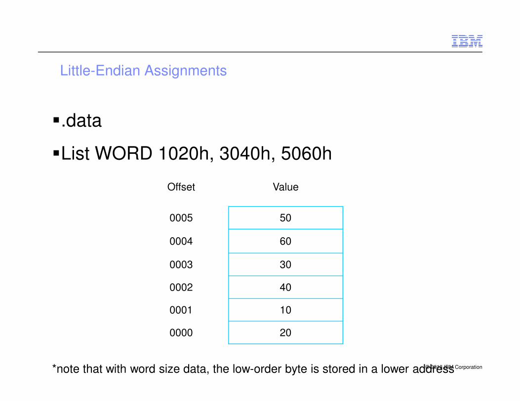
Little-Endian Assignments
�.data
�List WORD 1020h, 3040h, 5060h
Offset Value
© 2013 IBM Corporation
0005 50
0004 60
0003 30
0002 40
0001 10
0000 20
*note that with word size data, the low-order byte is stored in a lower address
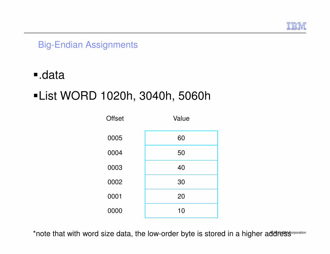
Big-Endian Assignments
�.data
�List WORD 1020h, 3040h, 5060h
Offset Value
© 2013 IBM Corporation
0005 60
0004 50
0003 40
0002 30
0001 20
0000 10
*note that with word size data, the low-order byte is stored in a higher address

Little-Endian Assignments
�.data
�List DWORD 10203040h, 50607080h
Offset Value
© 2013 IBM Corporation
0005 70
0004 80
0003 10
0002 20
0001 30
0000 40
*note that with word size data, the low-order byte is stored in a lower address
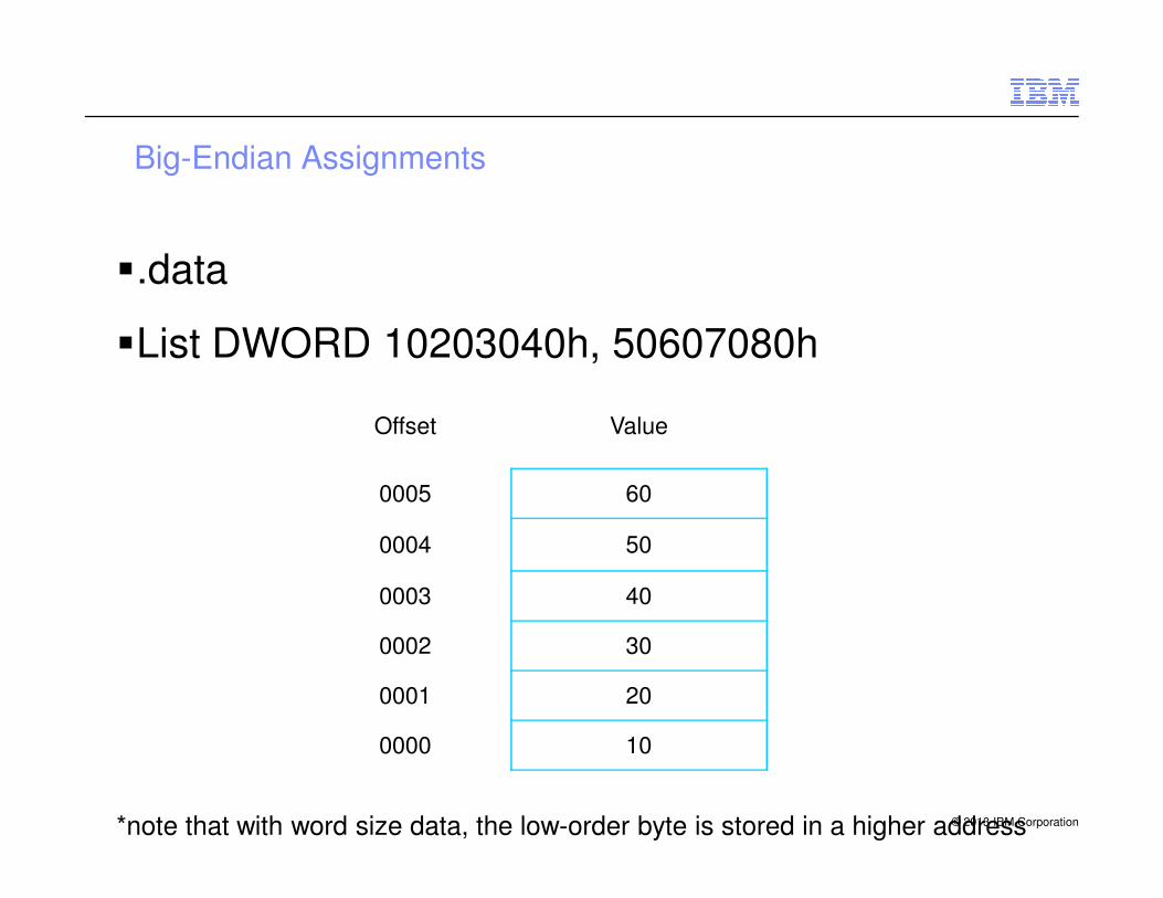
Big-Endian Assignments
�.data
�List DWORD 10203040h, 50607080h
Offset Value
© 2013 IBM Corporation
0005 60
0004 50
0003 40
0002 30
0001 20
0000 10
*note that with word size data, the low-order byte is stored in a higher address

Environment variable - F_UFMTENDIAN
Examples
� F_UFMTENDIAN=big
– All input/output operations perform conversion from big-endian to little-endian on
READ and from little-endian to big-endian on WRITE.
� F_UFMTENDIAN="little;big:10,20“
� F_UFMTENDIAN=big:10,20
© 2013 IBM Corporation
� F_UFMTENDIAN=big:10,20
� F_UFMTENDIAN=10,20
– The input/output operations perform big-endian to little endian conversion only on
unit numbers 10 and 20.
� F_UFMTENDIAN="big;little:8"
– No conversion operation occurs on unit number 8. On all other units, the
input/output operations perform big-endian to little-endian conversion.
� F_UFMTENDIAN=10-20
– The input/output operations perform big-endian to little-endian conversion on units
10, 11, 12 , ... 19, 20.
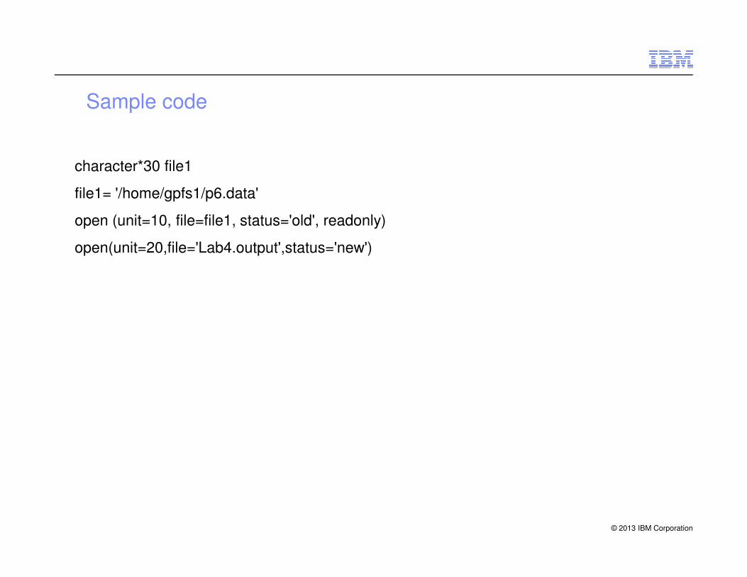
Sample code
character*30 file1
file1= '/home/gpfs1/p6.data'
open (unit=10, file=file1, status='old', readonly)
open(unit=20,file='Lab4.output',status='new')
© 2013 IBM Corporation

Compiler flag
� ifort -convert big_endian convert_data.f90
– The Intel compiler has a "-convert big_endian" flag to read and write big-endian
files.
© 2013 IBM Corporation
Next…
Job SchedulerIntel Cluster suite
© 2013 IBM Corporation
Intel Cluster suite