iii. r & d related to a future rare isotope … · r & d related to a future rare isotope...
TRANSCRIPT

III. R & D Related to a Future Rare Isotope Accelerator Facility -151-
III. R & D RELATED TO A FUTURE RARE ISOTOPE ACCELERATOR FACILITY OVERVIEW The Rare Isotope Accelerator (RIA), a next-generation facility for basic research in nuclear physics, continues to be a high priority for construction in the United States by the Department of Energy Office of Science. In late 2003 RIA was ranked a very high priority in the Office of Science 20-year plan. The CD-0 milestone for RIA was passed early in 2004. To prepare for RIA design and construction it is essential to continue a vigorous R&D program for RIA. This section is a progress report on the RIA R&D efforts at Argonne during 2004. The RIA R&D topics addressed at Argonne during the year 2004 are covered in three main sub-sections of this chapter: (A) Superconducting RF, (B) Beam Dynamics and Injectors, and (C) Rare Isotope Production and Separation. We continued to develop and improve the baseline design for the RIA proposal. Highlights of developments during 2004 include: • Completion of the design and significant progress on the construction of a
prototype RIA drift-tube cryomodule that will also be used for the ATLAS Energy Upgrade Accelerator Improvement Project.
• Successful operation of a fully dressed prototype triple-spoke beta = 0.5 superconducting drift-tube resonator.
• Continued development of the beam dynamics for an alternative RIA Driver Linac option based on a 345-MHz triple-spoke resonator including studies to quantify the effects of misalignment and RF setting errors, and the development of algorithms for optimization of the longitudinal tuning of multiple-charge-state beams.
• Application of a failure modes and effects analysis (FMEA) to the RIA driver linac design.
• Update of the design of the low q/m injector of the RIA RIB Post Accelerator.

-152- III. R & D Related to a Future Rare Isotope Accelerator Facility
• Significant progress towards to the construction of a full power prototype module of the RIA Driver RFQ.
• Preliminary development and design of a prototype system to demonstrate a
thin film liquid lithium stripper for the RIA driver linac. • Characterization of a full-scale RIA prototype fast gas catcher at the RIA
beam energies at the GSI Fragment Separator.

III. R & D Related to a Future Rare Isotope Accelerator Facility -153-
A. SUPERCONDUCTING RF a.1. Spoke Cavity Development for RIA (Z. Conway, J. Fuerst, M. Kedzie, M. Kelly, and
K. W. Shepard) A prototype 345 MHz, β = 0.5 triple-spoke cavity has been completed, the niobium cavity shell being enclosed in an integral stainless-steel helium jacket. The prototype has been tested at 4.2 K and 2 K, and could be operated cw at accelerating gradients exceeding 10 MV/m, as is detailed in Fig. III-1. With
an active length of 65 cm, at the gradients achieved, the cavity produces more than 6 MV of accelerating potential. The prototype shows good mechanical properties. The Lorenz de-tuning was measured to be 7 Hz per (MV/m)2 and microphonics were measured while operating at 9.5 MV/m at 4.2 K to be less than 2 Hz RMS.
Fig. III-1. Left: cut-away view of the prototype 345 MHz, β = 0.5 triple-spoke cavity showing the niobium shell contained within the integral stainless-steel helium jacket. Right: Cavity Q at 4.2 and 2 K. The cavity operated cw
at accelerating gradients of more than 10 MV/m. A prototype 345 MHz, β = 0.62 triple-spoke cavity has been completed, and the cavity is being readied for cold tests. Figure III-2 shows the 82 cm long
niobium shell just prior to attachment of the end-faces by electron beam welding
Fig. III-2. Niobium elements of the prototype β = 0.64 triple-spoke cavity after electropolishing and before the final
closure welds.

-154- III. R & D Related to a Future Rare Isotope Accelerator Facility
a.2. Superconducting Cavity Surface Processing Facilities (M. Kedzie, M. Kelly, and K. Shepard)
The Physics Division is coordinating construction of a surface processing facility for superconducting cavities at Argonne in a collaborative project with
Fermi National Accelerator Laboratory. Two chemical processing rooms and a 2500 CFM air-scrubber have been completed, as shown in Fig. III-3.
Fig. III-3. Chemical-processing rooms and a 2500 CFM air-scrubber, installed as part of a surface processing facility for superconducting cavities.
Installation of a class-100 clean area is underway, and is expected to be completed in 2005. The multi-partitioned clean area will have a latticed floor with an underlying drainage system which will facilitate a variety of configurations for ultra-pure, high-pressure water rinse-cleaning of superconducting components.
The completed facility will enable development of superconducting cavities and surface processing techniques for a variety of applications such as RIA, the 8 GeV proton driver, ILC, fourth-generation light-source, etc.
a.3. Tuners and Couplers for the RIA Cavities (Z. Conway, J. Fuerst, M. Kedzie,
M. Kelly, and K. W. Shepard) We are developing tuners and couplers to control the amplitude and phase of RF fields in the superconducting cavities to the level of precision
required for RIA. Figure III-4 shows a photograph of a prototype tuner installed on a spoke-cavity assembly and a microphonics response curve for the system.
III. R & D Related to a Future Rare Isotope Accelerator Facility -155-
Fig. III-4. A prototype piezo-electric fast tuner that can rapidly tune the rf frequency of the spoke-loaded cavity to
which it is attached by 800 Hz. This tuning bandwidth is much more than needed to control the observed microphonic detuning, which is typically 1 Hz.
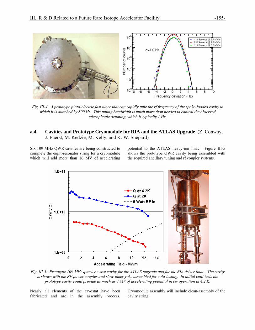
a.4. Cavities and Prototype Cryomodule for RIA and the ATLAS Upgrade (Z. Conway,
J. Fuerst, M. Kedzie, M. Kelly, and K. W. Shepard) Six 109 MHz QWR cavities are being constructed to complete the eight-resonator string for a cryomodule which will add more than 16 MV of accelerating
potential to the ATLAS heavy-ion linac. Figure III-5 shows the prototype QWR cavity being assembled with the required ancillary tuning and rf coupler systems.
Fig. III-5. Prototype 109 MHz quarter-wave cavity for the ATLAS upgrade and for the RIA driver linac. The cavity
is shown with the RF power coupler and slow-tuner yoke assembled for cold-testing. In initial cold-tests the prototype cavity could provide as much as 3 MV of accelerating potential in cw operation at 4.2 K.
Nearly all elements of the cryostat have been fabricated and are in the assembly process.
Cryomodule assembly will include clean-assembly of the cavity string.

-156- III. R & D Related to a Future Rare Isotope Accelerator Facility

III. R & D Related to a Future Rare Isotope Accelerator Facility -157-
B. BEAM DYNAMICS AND INJECTORS b.1. Design and Construction of a One-Segment Prototype of the RIA Driver RFQ
(P. N. Ostroumov, A. Barcikowski, F. DePaola, B. Rusthoven, S. Sharma, V. E. Vinogradov, D. Schrage,* and J. Rathke†)
We continue development of fabrication techniques for the 57.5 MHz driver linac RFQ. Successful tests of the RFQ prototype over a wide range of power levels (by a factor of 70) will demonstrate the feasibility of acceleration of masses from protons up to uranium in a single RFQ. The ANL infrastructure is being used for the preliminary machining, first-stage brazing, mechanical, vacuum and rf tests of the RFQ prototype. The work in 2004 has been concentrated on the fabrication of the resonator parts and preparation to the final machining, assembly and brazing. A full set of construction drawings has been completed. Significant contributions have been made by LANL and AES engineers to provide state-of-the-art fabrication technology for the OFE copper resonator. Figure III-6 shows a general view of the RFQ when completed. The right picture of Fig. III-6 presents an exploded view of major RFQ resonator parts that will be brazed together in a large high-temperature furnace in a hydrogen atmosphere using Cusil alloy
(72Ag-28Cu). To verify the correct engineering choice of the brazing seams and alloy we have performed a braze test for OFE copper pieces. The tests have confirmed the particular design of grooves for the alloy and overall brazing procedure. The brazed seams have been tested for vacuum and structural stability and have shown the expected performance. After the purchase of OFE copper for the vanes, quadrants and flanges, the material samples were sent for chemical analysis in terms of oxygen content. In some samples the oxygen content exceeded standard limitations and we have done ‘blister’ test of the material samples at ANL central shops. These tests have shown that the purchased OFE copper material is suitable to proceed with the high-temperature brazing. The OFE copper has been used for machining of all quadrants, vanes, flanges and end caps of the resonator. After preliminary machining of quadrants and vanes the water plugs and stainless steel insertions have been brazed. Figure III-7 shows a quadrant and a vane after the first-step brazing at ANL CMS. All manufacturing steps are completed except final machining and the following assembly of the resonator.
__________________ *Los Alamos National Laboratory, †Advanced Energy Systems.
1
23
4 Fig. III-6. Engineering 3-D model of the one-segment RFQ assembly (on the left) and exploded view (on the right).
1) vanes; 2) quadrant plates; 3) main flanges; 4) end caps.

-158- III. R & D Related to a Future Rare Isotope Accelerator Facility
Fig. III-7. Quadrant (on the left) and vane (on the right) after first-step brazing. b.2. Alternating-Phase Focusing in a Low-Velocity Heavy-Ion Superconducting Linac
(P. N. Ostroumov, K. W. Shepard, A. A. Kolomiets,* and E. S. Masunov†) The low-charge-state radioactive ion beam (RIB) accelerator requires strong transverse focusing, particularly at low velocities. For the charge-to-mass ratios considered here (q/A > 1/66) the proper focusing can be reached by using strong SC solenoid lenses with a field of up to ~15 T. Both the number of the solenoids and field can be reduced applying Alternating Phase Focusing (APF). A method to set the rf field phases has been developed and studied both analytically and with the help of the three-dimensional ray tracing code TRACK.1,2 As a reference design of the RIB linac we consider the focusing by high-field SC solenoids alternating with SC resonators. For the acceleration of heavy ions with q/A = 1/66 from 75 keV/u to 1.0 MeV/u with effective phase angle -20°, the RIB linac requires a
total of 63 resonators of four different types. The constant average beam radius along the linac can be provided with average focusing field 14.7 T. The cavities and solenoids will be distributed in seven cryostats with ~7 m length each. There is a drift space between the cryostats which is ~50 cm. Appropriate beam matching in both transverse and longitudinal phase space can be provided without any additional accelerating or focusing elements. However, careful tuning of the solenoids and resonator phases at each cryostat interface is required. Beam dynamics simulations in the reference design of the RIB linac performed with the code TRACK have shown that there is minor emittance growth along the structure as is seen in Fig. III-8.

III. R & D Related to a Future Rare Isotope Accelerator Facility -159-
0.05
0.10
0.15
0.20
0.25
0 10 20 30 40 50 60
0.1
0.2
0.3
Distance (m)
99.5%
99.5%
rms
rms
Longitudinal
Transversem
m m
rad
keV/
uns
ec
0.05
0.10
0.15
0.20
0.25
0 10 20 30 40 50 60
0.1
0.2
0.3
Distance (m)
99.5%
99.5%
rms
rms
Longitudinal
Transversem
m m
rad
keV/
uns
ec
Distance (m)
99.5%
99.5%
rms
rms
Longitudinal
Transversem
m m
rad
keV/
uns
ec
0.05
0.10
0.15
0.20
0.25
0 10 20 30 4
0.1
0.2
0.3
0.4
0.5
0Distance (m)
99.5%
99.5%
rms
rms
Longitudinal
Transverse
keV
/uns
ecm
m m
rad
0.05
0.10
0.15
0.20
0.25
0 10 20 30 4
0.1
0.2
0.3
0.4
0.5
0Distance (m)
99.5%
99.5%
rms
rms
Longitudinal
Transverse
keV
/uns
ecm
m m
rad
Figure III-8. Emittance evolution along the baseline (on the left) and CFS (on the right) designs of the RIB linac
simulated by the TRACK code. The reference design completely meets the specifications for the RIB linac. However, it is achieved with a significant number of solenoids and the linac is long. As a result the accelerating gradient real-estate is ~30% of the gradient provided by the SC cavities. Also, very high-field SC solenoids are required due to the high value of the defocusing factor in the SC resonators. The strong defocusing can be converted to focusing by applying an alternating phase focusing (APF). As a result, the accelerating gradient real-estate can be increased. To create the APF, the effective ‘synchronous’ phase angle ϕe must be alternated between positive and negative values. The analytical estimate has shown,1 that the simultaneous stability of the transverse and longitudinal motion can be achieved despite significant phase slippage of up to 100° in an individual cavity. However to create a sufficient stability area, large values of the effective phase angles ⎜ϕe⎜ in the cavities are required. The area of stability can be extended even for lower values of ⎜ϕe⎜by adding a solenoid into the focusing period that will also allow separate control of transverse and longitudinal beam dynamics. The combined focusing
structure (CFS) includes both SC solenoid and APF in every focusing period. We have designed an accelerator section from 75 keV/u to 1.0 MeV/u using CFS concept. Figure III-8 shows an evolution of transverse and longitudinal emittances in the CFS. As in the reference design there is no transverse emittance growth while the longitudinal rms emittance growth is 35% and emittance containing 99.5% of particles increases even more. The longitudinal emittance growth is a consequence of the electric field dependence from the radial coordinate in the low-velocity accelerating structures. This effect takes place in the first several resonators and can be minimized by lowering accelerating gradients or re-arranging the focusing period. Some additional studies are required to minimize the longitudinal emittance growth in the CFS. The CFS allows reduction of the number of solenoids more than 50% and reduces the real-estate length of the linac. In addition the required solenoid fields are lower. A significant saving in the total cost of the accelerator is expected. The disadvantage of the CFS is in strong coupling of the transverse and longitudinal degrees of ion motion and higher growth in longitudinal emittance. The combined focusing structure can be effectively used in many other applications of heavy ion accelerators.
__________________ *On leave from Institute of Theoretical and Experimental Physics, Moscow, Russia, †Moscow Physical Engineering Institute, Moscow, Russia. 1E. S. Masunov, D. A. Efimov, and P. N. Ostroumov, RF Focusing of Low-Charge-to-Mass-Ratio Heavy-Ions in a Superconducting Linac, Proc. of the EPAC-2004, Lucerne, Switzerland, p. 1405. 2P. N. Ostroumov, K. W. Shepard, A. A. Kolomiets, and E. S. Masunov. Alternating Phase Focusing in Low-Velocity Heavy-Ion Superconducting Linac, Proc. of the LINAC-2004, Lubeck, Germany, p. 374.

-160- III. R & D Related to a Future Rare Isotope Accelerator Facility
b.3. Design Update of the Injector Section of the RIA Post-Accelerator (P. N. Ostroumov, A. A. Kolomiets, and V. N. Aseev)
The original design of the injector section of the post-accelerator included a 380 kV open-air variable-voltage platform that consist of a multi-harmonic buncher, first two sections of 12 MHz RFQ, and both helium gas stripper cells. Our objective of the front end design modifications was to reduce the potential of the HV deck significantly while keeping capabilities to form high quality beams. Main features of the updated design of the RIB injector are: • Beam energy of ions entering RFQ is
significantly reduced down to 0.4 keV/u which allows us to lower the bias potential of the HV deck;
• Ion source voltage can be reduced down to
60 kV; • Use an external buncher and additional bunching
inside the RFQ; • Use a separate beamline for acceleration of ions
with mass numbers below 66. The beamline #2 may be necessary if the main beamline #1 is not stable at very low rf power level tuned for acceleration of light ions.
The simplified layout of the RIB injector section without focusing elements is shown in Fig. III-9. Ions with charge-to-mass ratio in the range 1/240 ≤ q/A ≤ 1/66 are accelerated in line #1 that consists of conventional RFQ and Hybrid RFQ (HRFQ). Both structures are operated at 12.125 MHz. Energies of the beam exiting RFQ (7.4 keV/u) and HRFQ (24.4 keV/u) have been chosen to optimize efficiency of the gas stripping.
To adjust energies of different ions extracted from ion source at constant voltage 60 keV, the RFQ is placed on open-air HV deck, potential of which should be adjusted within -26 kV ≤ U ≤ 44 kV to obtain the required velocity for different ions. The accelerating structures on beamline #1 require very low rf power for acceleration of light ions that can be unstable due to multipacting, for example. Beamline #2 can be constructed specifically for the acceleration of light ions. The RFQ on beamline #2 operates at 24.25 MHz and requires an injection energy of 1.6 keV/u. The latter requires a voltage adjustment of the HV deck in the range -46 kV ≤ U ≤ 52 kV. Note, the bunching frequency is 12.125 MHz which is the fundamental frequency in the post-accelerator. Due to the fact that RFQ focusing is scaled as
2λqA ,
where λ is the rf wavelength, the RFQs on both beamlines can be designed with the same average radius R0 and inter-electrode voltage. Beams from both lines enter the second HRFQ operating at 24.25 MHz and are accelerated up to 92.7 keV/u which is sufficient to inject into the SC linac. The longitudinal emittance of heavy-ion beam is formed using a two-stage bunching process. The TRACK simulations have been performed using full 3D fields. The results obtained for 2⋅105 simulated particles with charge-to-mass ratio q/A = 240 in beamline #1 are shown in Fig. III-10. Longitudinal emittance evolution along the front-end structures is shown in Fig. III-11. Table III-1 lists emittance values along the elements of the RIB injector.
__________________ 1P. N. Ostroumov, M. P. Kelly, A. A. Kolomiets, J. A. Nolen, M. Portillo, and K. W. Shepard, A Post Accelerator for the U.S. Rare Isotope Accelerator Facility, Nucl. Instrum. Methods B204, 433 (2003).

III. R & D Related to a Future Rare Isotope Accelerator Facility -161-
High Voltage PlatformBuncherStripper
IS
V=60
kV
24 M
Hz
HR
FQ
Beamline 2
Beamline 1
12 MHz RFQ 12 MHz HRFQ
24 MHz RFQ
High Voltage PlatformBuncherStripper
High Voltage PlatformBuncherStripper
IS
V=60
kV
24 M
Hz
HR
FQ
Beamline 2
Beamline 1
12 MHz RFQ 12 MHz HRFQ
24 MHz RFQ
IS
V=60
kV
24 M
Hz
HR
FQ
Beamline 2
Beamline 1
12 MHz RFQ 12 MHz HRFQ
24 MHz RFQ
Fig. III-9. Schematic layout of upgraded front end of the RIA post-accelerator.
Phase (deg) Phase (deg)
dW/W
(%)
dW/W
(%)
A B
Phase (deg) Phase (deg)
dW/W
(%)
dW/W
(%)
A B
Fig. III-10. Beam longitudinal phase space plots after the external buncher (A) and RFQ internal buncher (B). The
red dashed line represents the RFQ separatrix.
A B C
Phase (deg)Phase (deg) Phase (deg)
dW/W
(%)
dW/W
(%)
dW/W
(%)
A B C
Phase (deg)Phase (deg) Phase (deg)
dW/W
(%)
dW/W
(%)
dW/W
(%)
Fig. III-11. Beam longitudinal phase space plots after the RFQ (A), Hybrid RFQ (B) and second Hybrid RFQ (C).

-162- III. R & D Related to a Future Rare Isotope Accelerator Facility Table III-1. Beam parameters along the injector elements of beamline #1.
RFQ HRFQ 1 HRFQ 2 Beam energy (keV/u) 7.4 24.4 92.7 Long. emittance (4 rms, keV/u⋅nsec) 0.057 0.059 0.065 Long. emittance (95%, keV/u⋅nsec) 0.082 0.098 0.103 Trans. emittance (4 rms, π mm⋅mrad) 0.035 0.036 0.039 Trans. emittance (95%, π mm⋅mrad) 0.041 0.043 0.051
b.4. Progress with the 2Q-LEBT Prototype (N. E. Vinogradov, P. N. Ostroumov, R. Pardo,
and R. Scott) A prototype injector of the RIA Driver Linac is being developed at the high bay area of the Physics Division Dynamitron. On the final stage of the project, the prototype called 2Q-LEBT will include an ECR ion source installed on 100 kV high voltage platform, an achromatic bending system consisting of two 60° bending magnets, a gridless multi-harmonic buncher and 57.5 MHz RFQ segment. At the present moment, the 2Q-LEBT facility consists of BIE-100 ECR ion source, 60° bending magnet and beam diagnostic system. A number of modifications were implemented to increase beam production performance of the original source. A new Einzel lens, a puller, a high voltage insulator between source body and main beamline have been fabricated. Additionally, we have redesigned the injection assembly and heating oven, and equipped the facility with a new interlock system. A dipole magnet has been installed in the beamline downstream of the Einzel lens for vertical steering of the beam. In some cases, adjustment of the beam position in vertical direction allows us to increase output current up to
30%. For careful studies of the output beam the emittance measurement station based on a combination of slit and scanning wire have been designed and built. A fully automatic LabVIEW control system provides user with an on-line data treatment. At present, comprehensive measurements of various beams are being carried out. Figure III-12 represents an example of Argon beam spectrum measured at relatively low level of the rf power. Three typical patterns of measured beam emittances are shown in Fig. III-13. In the concept of simultaneous acceleration of two charge states developed for the RIA, it is assumed that the ECR source forms a beam with similar phase space distributions of the neighboring charge states. Typical values of different charge state intensities along with corresponding normalized emittances and Twiss parameters are listed in Table III-2. As is seen in the table, Twiss parameters of different charge states generated by BIE-100 are very close to each other. Installation of the HV platform and related equipment including isolation transformer is planed to complete in 2005.

III. R & D Related to a Future Rare Isotope Accelerator Facility -163-
1000 1200 1400 1600 1800 2000 22000
10
20
30
40
50
60
70
Beam
Inte
nsity
, uA
BM Field, G
+7Ar
+8Ar
+9Ar+10Ar
1000 1200 1400 1600 1800 2000 22000
10
20
30
40
50
60
70
Beam
Inte
nsity
, uA
BM Field, G
+7Ar
+8Ar
+9Ar+10Ar
Fig. III-12. Argon charge state distribution at 250 W rf power and 20 kV source bias.
Argon 9+
-20 -15 -10 -5 0 5 10 15 20-30
-20
-10
0
10
20
30
X, mm
X',
mra
d
-20 -15 -10 -5 0 5 10 15 20-30
-20
-10
0
10
20
30
X, mm
X',
mra
d
Argon 7+
-20 -15 -10 -5 0 5 10 15 20-30
-20
-10
0
10
20
30
X, mm
X',
mra
d
Argon 8+ Argon 9+
-20 -15 -10 -5 0 5 10 15 20-30
-20
-10
0
10
20
30
X, mm
X',
mra
d
-20 -15 -10 -5 0 5 10 15 20-30
-20
-10
0
10
20
30
X, mm
X',
mra
d
Argon 7+
-20 -15 -10 -5 0 5 10 15 20-30
-20
-10
0
10
20
30
X, mm
X',
mra
d
Argon 8+
Fig. III-13. Typical emittance patterns for Argon beam.
Table III-2. Beam intensities, normalized emittances and Twiss parameters for sample Argon and Xenon beams.
Charge State Intensity, eµA Normalized RMS emittance, πmmmrad
α β, mm/mrad
+7Ar 22 0.07 -2.08 1.23 +8Ar 49 0.07 -1.9 1.28 +9Ar 19 0.05 -2.3 1.18 +13Xe 20 0.10 -1.1 0.83 +14Xe 17 0.10 -1.3 0.97 +15Xe 14 0.11 -1.34 0.91
b.5. Modifications and rf Tests of the 12 MHz RFQ for Acceleration of a 240U1+ Beam
(P. N. Ostroumov, A. A. Kolomiets, and N. E. Vinogradov) A proper choice of the peak surface field Ep is extremely important for reliable cw operation of accelerating structures. In the case of RFQ, Ep is
defined by breakdown voltage between adjacent electrodes which depends on vane tip width, average aperture and electrodes modulation. The available

-164- III. R & D Related to a Future Rare Isotope Accelerator Facility experimental data can not be directly extended to any type of RFQ structure due to strong dependence of the breakdown limit on operating frequency, shape and material of electrodes, manufacture and assembly procedures, conditioning and other features of the specific design. A full power prototype of the 12 MHz split-coaxial RFQ structure for the RIA post-accelerator has been designed and tested for acceleration of Xe1+ beam.1 It has demonstrated a high performance enabling one to achieve ~130 MV/m peak surface field at 90 kV inter-vane voltage and mean bore radius of 10 mm. At the same time, a resonator detuning and reduction of the quality factor have been observed at ~90 kV due to over-heating of vane tips which are not directly water cooled.1 We propose to modify the split-coaxial electrodes for acceleration of 240U1+ beam and include appropriate water cooling of vanes. The design value of the peak surface field for the new RFQ vanes is based on operational experience of the 12 MHz RFQ
prototype1 and ISAC 35 MHz RFQ.2 The computer simulations by the code CST EM Studio have been performed to define Ep for the existing and proposed geometries of modulated vanes (see Fig. III-14). The simulation results are consistent with the reported experimental data within less than 10%. According to this model, the 12 MHz RFQ for acceleration of a 240U1+ beam can be designed with 6.8 mm average aperture radius and 2.6 mm vane tips curvature radius. The required inter-vane voltage is 68 kV and corresponds to Ep = 135 kV/cm, which is slightly lower than in the ISAC RFQ. To verify the breakdown voltage we propose to carry out high power rf test using the existing 12 MHz RFQ tank. The RFQ tank is being prepared for this test. Currently, we are modifying the vacuum system of the tank to use one turbo pump in combination with oil-free scroll backing pump and one or two 500 l/s Perkin Elmer ions pumps for continuous operation. A special fixture table equipped with alignment mechanism is being designed and fabricated to replace the vanes of the RFQ.
__________________ 1M. P. Kelly et al., Proc. of the 2001 PAC Accel. Conf., Chicago, p. 506, 2001. 2R. L. Poirier et al., Proc. of the 2000 Linac Conf., Monterey, CA, p. 1023.
CST Model of an RFQ Electrodes Electric Field DistributionCST Model of an RFQ Electrodes Electric Field Distribution
Fig. III-14. Modulated RFQ vanes in the CST EM Studio model.
b.6. Error Simulations and Beam Loss Studies in the RIA Driver Linac (B. Mustapha,
P. N. Ostroumov, and V. A. Aseev) The RIA Facility includes a high-intensity 1.4 GeV driver linac. To avoid problems from beam-induced radio-activation, beam losses must be limited to low values, particularly in the high-energy section of the linac, where the fractional beam loss must be less than 10-4. Beam dynamics studies including all sources of error are necessary in order to identify the possible sources of beam halo formation that could lead to excessive beam losses. The study of beam
losses to the level of 10-4-10-5 requires the simulation of large number of particles which calls for the use of parallel computing. The code TRACK was then parallelized and simulations performed on the computer cluster JAZZ at Argonne. End-to-end (from the ECR ion source to the target) simulations including all possible sources of error were performed in order to study the effect of the different errors and identify the most critical ones. The simulations were performed for a multi-

III. R & D Related to a Future Rare Isotope Accelerator Facility -165- component uranium beam: 2 charge states (28+,29+) in the injector and the low energy section, 5 charge states (74+,75+,76+,77+,78+) after the first stripper and 5 charge states (87+,88+,89+,90+,91+) after the second stripper. It was found1 that the RF field errors (phase and amplitude) and the stripper thickness fluctuations are the most critical errors significantly affecting the longitudinal emittance of the beam and eventually producing beam losses. In order to study eventual beam losses, high-statistics simulations were performed for 6 different combinations of most critical errors (see Table III-3) and for both the baseline and the Triple-spoke designs of the driver linac. The two designs differ mainly by the type of cavities used in the high-energy section of the linac. In the Triple-spoke design, the recently developed triple-spoke cavities replace the elliptical-cell cavities used in the original baseline design. The results show that the baseline design is in general more sensitive to these errors and to the overall tuning of the linac. Beam losses were observed in the high-energy section for the baseline design whereas no losses for the Triple-spoke design even for the highest error amplitudes (see Table III-3). To quantify these losses, Fig. III-15 shows the losses in
Watts/m along the linac for each error combination and both designs. The horizontal red line is the 1 Watts/m limit required for hands-on maintenance of the linac. The first two peaks in all plots correspond to the losses at the two strippers. The losses at the strippers are controlled because they will be stopped in specifically designed collimators. The uncontrolled losses observed in the high-energy section of the baseline design are small for combinations 1&2, about 1 Watts/m for combinations 3&4 and about 10 Watts/m for combinations 5&6. No uncontrolled losses for the Triple-spoke design. It is clear that to keep uncontrolled losses below the 1 Watts/m limit for the baseline design, the RF field errors should not exceeds 0.5° for the phase and 0.5% for the amplitude and the stripper thickness fluctuation should be about 5%. However, the Triple-spoke design may tolerate higher errors. The preliminary conclusion of these studies is that due to its larger longitudinal acceptance the Triple-spoke design is more tolerant of errors without producing uncontrolled beam losses. The study also showed that the losses in the baseline design are extremely sensitive to the longitudinal tuning in the linac. A careful tuning in terms of phase setting to produce the lowest possible effective emittance at the location of the strippers, especially in the medium-energy section, was proven to reduce the losses in the subsequent high-energy section.
Table III-3: Uncontrolled beam losses for 6 combinations of most critical errors and for both the baseline and the Triple-spoke designs.
Combination RF errors Stripper Thickness fluctuation
Baseline design Triple-spoke design
1 Field: 0.3%, Phase: 0.3 deg 5% FWHM 3.0 10-8 0.0
2 Field: 0.3%, Phase: 0.3 deg 10% FWHM 8.2 10-7 0.0
3 Field: 0.5%, Phase: 0.5 deg 5% FWHM 5.5 10-5 0.0
4 Field: 0.5%, Phase: 0.5 deg 10% FWHM 2.7 10-4 0.0
5 Field: 0.7%, Phase: 0.7 deg 5% FWHM 1.4 10-3 0.0
6 Field: 0.7%, Phase: 0.7 deg 10% FWHM 2.6 10-3 0.0
__________________ 1P. N. Ostroumov, V. N. Aseev, and B. Mustapha, Phys. Rev. ST. Accel. Beams 7, 090101 (2004).

-166- III. R & D Related to a Future Rare Isotope Accelerator Facility
Fig. III-15. Beam losses in Watts/m along the linac for 6 combinations of most critical errors and both the baseline and the Triple-spoke designs. Explanations are given in the text.
b.7. Longitudinal Fine-Tuning of a Multiple-Charge-State Heavy-Ion Beam
(B. Mustapha and P. N. Ostroumov) In a recent study1 we reported the results of large scale simulations for two design options of the RIA driver linac. The two design options are the original baseline design and the alternative triple-spoke design. They differ mainly by the type of cavities used in the high-energy section of the linac. In the triple-spoke design, the recently developed triple-spoke cavities replace the elliptical-cell cavities used in the baseline design. The simulations for both designs were performed for a multiple-charge-state uranium beam using the recently developed beam dynamics code TRACK. The simulations included all sources of error such as elements misalignment, rf field errors and stripper thickness fluctuations. A thorough beam loss analysis has been performed showing that the baseline design is less tolerant to rf field errors and to fluctuations in the stripper thickness. Beam losses were observed in the high-energy section of the baseline design while no losses were observed in the triple-spoke design even for the highest error amplitudes. The study also showed that the losses in the baseline design are extremely sensitive to the longitudinal tuning in the linac. A
careful tuning in terms of phase setting to produce the lowest possible effective emittance at the location of the strippers, especially in the medium-energy section, was proven to reduce the losses in the subsequent high-energy section. We here focus on the baseline design and attempt to develop tunes that significantly reduce beam losses. For a fast and reliable way to longitudinally fine tune a multiple-charge-state heavy-ion beam we started developing an automatic procedure to replace the slow and often less than optimal manual procedure. But prior to implementing the automatic tuning procedure we investigated few simple and efficient ways of doing it manually. Among these methods, and of particular interest from beam dynamics standpoint, we tried to bring the reference phases of individual charge state beams to their corresponding synchronous phases. For this we considered a design option where a single cavity type (single frequency) is used in the medium-energy section of the RIA driver. Figure III-16(a) shows the evolution of beam phase and energy centroid

III. R & D Related to a Future Rare Isotope Accelerator Facility -167- deviations of the individual charge states throughout the whole section. In this case and for simplicity, all cavity phases were set to –30°. We clearly notice that the reference phase and energy of the five charge states (74+,75+,76+,77+,78+) oscillate around those of the reference charge state (76+) corresponding to the horizontal lines. By setting the phases of two particular cavities at the beginning of the section to -90°, converting them into bunchers, we were able to suppress or significantly reduce the phase and energy
oscillations of individual charge state beams about those of the reference charge state, see Fig. III-16(b). We clearly see that the oscillations around the reference charge state are either absent or significantly reduced which usually results in more stable beam dynamics along the linac. However, to bring the centers of individual beams together at the end of the section we had to use 4 cavities and set them to -90° with 15% increase in their field levels.
Fig. III-16. Beam phase and energy centroid deviations for the five charge states (dashed curves) with respect to
the reference charge state (solid line) plotted as function of distance along the single frequency option of the medium-energy section of the RIA driver linac. (a) Case where all cavity phases are set to -30° showing the
oscillations of individual charge state beams. (b) Case where few cavities are used to bring the reference phases of individual charge state beams to their corresponding synchronous phases in order to limit beam oscillations and
produce more stable beam dynamics. Bringing the reference phases of the individual charge state beams to their corresponding synchronous phases has the advantage of producing a much more stable beam dynamics by significantly reducing beam oscillations at the cost of few additional cavities. However, this method is more useful for a single frequency lattice and will be hard to apply in our case where two different cavity types
with different frequencies are used in the medium-energy section of the linac. It also does not necessarily match the Twiss parameters of the different charge state beams, which is required to produce a minimal overall beam emittance. For these reasons we are developing a fully automatic longitudinal beam tuning procedure for multiple-charge-state heavy-ion beams.
__________________ 1P. N. Ostroumov, V. N. Aseev, and B. Mustapha, Phys. Rev. ST. Accel. Beams 7, 090101 (2004). b.8. Front End Design of a Multi-GeV H-Minus Linac (P. N. Ostroumov, K. W. Shepard,
G. W. Foster,* I. V. Gonin,* and G. V. Romanov*) The proposed 8-GeV driver at FNAL is based on 422 independently phased SC resonators. Significant cost saving is expected by using an rf power fan out from high-power klystrons to multiple cavities. Successful development of superconducting (SC) multi-spoke resonators operating at ~345-350 MHz provides a strong basis for their application in the front end of
multi-GeV linear accelerators. Such a front-end operating at 325 MHz would enable direct transition to high-gradient 1300 MHz SC TESLA-style cavities at ~400 MeV. The proposed front end consists of 5 sections: a conventional RFQ, room-temperature (RT) triple-spoke resonators, single-, double- and triple-spoke super-conducting resonators. There is a large advantage

-168- III. R & D Related to a Future Rare Isotope Accelerator Facility in using independently phased RT TSRs between the RFQ and SC sections in the energy range 3-15 MeV. These resonators (see Fig. III-17) operate on π-mode and provide extremely high shunt impedance which
changes from 160 MΩ/m to 80 MΩ/m for given energy range 3-15 MeV. The compact RT-TSRs will be alternated with SC focusing solenoids providing strong focusing.
Fig. III-17. Cut-out view of the RT-TSR. Beam dynamics studies show that the proposed front end can provide high quality beams and its tune does not depend from the current. Figure III-18 shows 30 mA beam rms and total envelopes in the front end
from 65 keV to 410 MeV. About 2 mA of the beam injected into the RFQ is not accelerated and lost primarily on the collimators in the Medium Energy Beam Transport (MEBT).
__________________ *Fermi National Accelerator Laboratory.
0 10 20 30 40 50 60 70 80 90 100 110 120-4
-3
-2
-1
0
1
2
3
4
Bea
m s
ize
(cm
)
DIstance (m)
x_rms[cm] y_rms[cm] Xmax[cm] Ymax[cm]
RFQ, MEBT, RT-TSR, SSR, DSR, TSR
Fig. III-18. Beam envelopes of 30 mA H-minus beam in the front end of the 8-GeV linac. The black solid line shows the aperture.

III. R & D Related to a Future Rare Isotope Accelerator Facility -169-
b.9. Reliability and Availability Studies in the RIA Driver Linac (E. S. Lessner and P. N. Ostroumov)
The Rare Isotope Accelerator (RIA) facility will include various complex systems and must provide radioactive beams to many users simultaneously. The availability of radioactive beams for most experiments at the fully-commissioned facility should be as high as possible within design cost limitations. To make a realistic estimate of the achievable reliability a detailed analysis is required. The RIA driver linac is a complex machine containing a large number of superconducting (SC) resonators and capable of accelerating multiple-charge-state beams. At the pre-CDR stage of the design it is essential to identify critical facility subsystem failures that can prevent the driver linac from operating. The reliability and availability of the driver linac were studied using expert information and data from operating machines such as ATLAS, APS, JLab, and LANL. Availability studies are performed with a Monte-Carlo simulation code previously applied to availability assessments of the NLC facility and the results used to identify subsystem failures that most affect the availability and reliability of the RIA driver, and guide design iterations and component specifications to address identified problems. Analysis of the RIA SC linac driver availability is based on simulations using a code developed at SLAC to assess the impact of various technologies or configuration choices in the Next Linear Collider (NLC) performance. The code emulates failures in a Monte-Carlo process that uses real-time as the independent variable. It calculates the machine average availability based on: i. given Mean Time Between Failures (MTBF) and
Mean Time To Repair (MTTR) values for each component,
ii. degradation of parameter affected by component failure,
iii. redundancy of components, iv. number of repair people available for tunnel
access, v. recovery and tuning time, and vi. total number of people available for repairs. A detailed list of machine components, and, for each component, its number, MTBF and MTTR are required. Availability data for individual components were based on data from different accelerator facilities, namely ATLAS, APS, JLab, LANL, and
from reports of planned machines such as NLC and APT. Also required is an estimate of the degradation in the appropriate machine parameter caused by a component failure. For instance, we can tune around a failed resonator and degrade the beam energy by the resonator’s accelerating field integrated over its length. Access requirement are divided in three categories: a) component failure brings the accelerator down but does not require access to repair, b) repair/replacement of the component requires access to the accelerator tunnel, or c) the component can be repaired while the accelerator is running (“hot repair”). Included in the category of “broken but no access needed” are failures of single resonators that require rephasing of neighboring resonators (retuning) and may degrade the beam energy, but repair can wait until a long access is required. The calculations take into account the constraints imposed by the number of people available for repair during an access. For the availability analysis of the SC driver linac we imposed that a minimum beam power at the target be maintained, while, at this stage of the machine design, making assumptions about component failure effects. These assumptions were based on the performance of existing accelerators and experienced operators, and need to be validated with detailed Failure Modes and Effects Analysis (FMEA) studies. Listed below are some of the requirements and assumptions made. • Some parameters have a minimum value that, when
reached, cause the accelerator to be declared broken. The meaningful parameter for RIA is the beam power on the target, which will be specified as a percentage of the user requested beam power. As an initial assumption, the minimum acceptable beam power is set to 60% of the user requested power. Since beam power is proportional to its energy and intensity, both energy and current are used as “budget” parameters according to the criteria given below.
• Some component failures cause the machine to go down, such as failure of the Machine Protection System, and require immediate tunnel access to repair; others cause the machine to go down, but the machine can be retuned without tunnel access.
• Each time a component breaks the intensity is decreased by the specified amount, and the component is scheduled for repair, immediately if it can be fixed hot, or at the next downtime. When the minimum allowed operational energy or intensity is

-170- III. R & D Related to a Future Rare Isotope Accelerator Facility
reached the accelerator is declared broken, and many accumulated repairs are done.
• Downtime planning: after a budget parameter reaches its allowable limit, the code computes the time necessary to fix the components affecting the parameter. An additional time can be added to the downtime to repair other components.
• Except for the first cryostat in the low-energy section, where failures cause the beam to be lost, failure of a whole cryostat can be recovered by retuning.
• Amplifiers and other RF power equipment are situated in a separate utility building and can be replaced quickly, if there is sufficient redundancy.
• Solenoid failure increases beam losses by 10%. Beam can be retuned, with a MTTR of 4 hours. The driver is declared broken if losses are higher than twice the initial nominal setting.
• Quadrupoles are warm. Failure increases beam losses by 10%.
• Power supplies, water pumps, etc, are located in the support building and can be repaired hot.
For the current design, with values based on the historical data and engineering expertise from many accelerator groups the SC linac availability is 96%. The high availability comes from assuming an “universal spare” cold cryostat that can be used to replace a broken unit in eight hours, SC magnets run in persistent mode, high redundancy of power supply elements for the warm magnets and redundant amplifiers and klystrons. By assuming a support building, where power supply and controllers, and RF power sources are located, the number of tunnel accesses is reduced significantly. Figure III-19 shows the preliminary results for estimates of downtime based on this analysis
RF structure13.8%
rf power sources59.7%
Diagnostic1.1%
Controls7.1%
Cryo0.9%
AC power7.5%
Vacuum8.9%
Front End15.6%
Cryo Plant 7.7%
Site Power 5.3%
Sitewide Controls
5.7% Medium Energy21.4%
High Energy24.9%
Low
Fig. III-19. The distribution of downtime per region is shown on the left. Distribution due to systems contributing
more than 0.4% of the SC linac downtime is shown on the right. b.10. Optimization of Steering Elements in the RIA Driver Linac (E. S. Lessner,
V. S. Aseev, and P. N. Ostroumov) The driver linac of the projected RIA facility is a versatile accelerator, a 1.4-GV, CW superconducting (SC) linac designed to simultaneously accelerate several heavy-ion charge states, providing beams from proton to uranium at 400 MeV/u at power levels at a minimum of 100 kW and up to 400 kW for most beams. Acceleration of multiple-charge-state uranium beams places stringent requirements on the linac design. A steering algorithm was derived that fulfilled the driver’s real estate requirements, such as placement of steering dipole coils on SC solenoids and of beam position
monitors outside cryostats, and beam-dynamics requirements, such as coupling effects induced by the focusing solenoids. The algorithm has been fully integrated into the tracking code TRACK and it is used to study and optimize the number and position of steering elements that minimize the multiple-beam centroid oscillations and preserve the beam emittance under misalignments of accelerating and transverse focusing elements in the driver linac (see Table III-4 for a listing of the elements used in this analysis).

III. R & D Related to a Future Rare Isotope Accelerator Facility -171-
A correction algorithm applied to the driver must comply with real-estate limitations of very tight drift spaces and coupling introduced by solenoidal focusing elements was derived previously. In this paper, we present the algorithm as fully implemented in the code TRACK, a multi-purpose tracking simulation code specially suited to simulations of acceleration of heavy-ions in SC linacs. The algorithm has been rewritten for computational efficiency, and has additional features such as the assignment of accuracy and precision errors to each monitor. We present the algorithm in its new implementation and preliminary studies to optimize the number and location of steering elements in the SC driver linac.
The algorithm can be implemented in “correction sections”, whereby N correctors and M monitors are related by: (R + ∆R) F = - (X + ∆X), (2) where R and X represent the transport matrix and monitor vector coordinates for the ideal lattice, respectively. ∆R denotes the matrix deviations due to lattice errors (misalignments and field errors), and ∆X are errors in the monitor-coordinates vector introduced by monitor inaccuracies. The corrector strengths are then determined by minimizing the function Ω given in Eq. 3. Ω includes statistical weights, wi, useful in evaluating the correction scheme effectiveness. The minimization must obey constraints imposed by realistic limits, C, on the corrector strengths:
2
2 1
1
( )( ) , .
x yN N
ik ik k i iM kk k
i i
R R F X XF F
w
+
=
=
⎛ ⎞+ ∆ + + ∆∑⎜ ⎟
⎜Ω = ≤∑⎜ ⎟⎜ ⎟⎝ ⎠
C⎟ (3)
Figure III-20 displays a possible scheme for a correction section.
mon
1
mon
2
mon
3
Q1 S1 Q2
corr
2
corr
1
corr
3
corr
5
corr
4n
swtc
h
n sw
tch
n cd
ump
n cd
ump
n cd
ump
TANK TANK
mon
1
mon
2
mon
3
Q1 S1 Q2
corr
2
corr
1
corr
3
corr
5
corr
4n
swtc
h
n sw
tch
n cd
ump
n cd
ump
n cd
ump
TANK TANK
Fig. III-20. A possible correction section showing focusing, steering elements, and tanks, or cryostats, containing accelerating elements. The correctors in light blue correspond to correctors not used in the depicted correction
section. Table III-4. Steering elements distribution in the three SC driver sections. Accelerating and focusing components are also shown.
Element Low Energy Medium Energy High Energy
Resonator 83 184 172
Solenoid 40 45 0
Quadrupole 0 0 84
Corrector 13 19 22
Monitor 7 18 41

-172- III. R & D Related to a Future Rare Isotope Accelerator Facility Figures III-21 and III-22 show the corrected horizontal beam envelope for 60 seeds, and the
corresponding vertical (top) and horizontal (bottom) corrector strength distributions, respectively.
0 100 200 300 400 5000.0
0.5
1.0
1.5
2.0
2.5
3.0
3.5
4.0
high
bet
a
med
ium
bet
a
low
bet
a
2nd
chic
ane
1st c
hica
ne
Hor
izon
tal B
eam
Env
elop
e (c
m)
Distance (m)
Fig. III-21. Corrected horizontal envelope, where the aperture radius is indicated for 60 seeds.
-1.5 -1.0 -0.5 0.0 0.5 1.0 1.50
50100150200250300
Horizontal Mean = 0.00Sigma = 0.39Fr
eque
ncy
of O
ccur
renc
es
Corrector Strength (T.cm)
-1.5 -1.0 -0.5 0.0 0.5 1.0 1.50
50100150200250300
Vertical Mean = 0.01Sigma = 0.36
Fig. III-22. Vertical (top) and horizontal (bottom), corrector strength distributions over 60 seeds.
Simulations were carried for random-uniform resonator misalignments of 0.05-cm, solenoid misalignments varying from 0.015 for the shortest solenoids up to 0.05-cm for the longest solenoids, and quadrupole misalignments of 0.02 cm. Monitor precision errors were set at 100 µm. A 4D minimization algorithm tailored to multiple-beam steering can correct position and angle and
account for solenoid-induced couplings. It is a beam-based algorithm and amenable to be implemented experimentally. It has been optimized for computational efficiency in its full integration in TRACK. It is being used to optimize the number and position of correcting elements in the RIA driver linac. Additional features will include a realization of correction by dipole coils mounted on solenoids and automatic evaluation of correction scheme effectiveness.

III. R & D Related to a Future Rare Isotope Accelerator Facility -173-
C. RARE ISOTOPE PRODUCTION AND SEPARATION c.1. Characterization Studies of Prototype ISOL Target Material for RIA
(John P. Greene, Janelle Neubauer, Jerry A. Nolen, Tatiana Burtseva,* Antonio C. C. Villari,† and Itacil C. Gomes‡)
One option as a high power isotope separator on-line (ISOL) production target proposed for the Rare Isotope Accelerator (RIA) will be one based on fission from uranium or a compound of uranium to produce ion species far from stability.1 The two-step target design employs neutrons first generated in a cooled, refractory, primary target which then induce fission in a surrounding assembly of uranium carbide. The prototype target design was done by TechSource, Inc.2 with the fine-grained, high thermal conductivity UC2 target material to be supplied by Argonne National Laboratory (ANL). The primary target will be a liquid cooled tungsten cylinder, irradiated by the RIA driver beam. The small energy deposition rate in the surrounding UC2 secondary target material is not sufficient to heat the target to the desired operating conditions (1600 to 2100 C) necessary to promote effective release of fission products. Thermal conductivities on the order of 2 W/m-K (or greater) over the operating temperature range are required for a viable secondary target design. A second spallation target approach involves exposing a tilted target slab to the full power primary beam but at an oblique angle, thereby dispersing the energy deposited over a large area.3 The use of fissionable target material would allow for a broad range of interesting isotopes to be produced. The target would possess a high thermal conductivity along its planar dimensions and yet be thin enough to allow rapid diffusion of fission products out of the target surface. The simple design would also allow for near term testing in high power beams while work progresses on the two-stage target. As the original material used for this research is no longer commercially available, an effort was immediately mounted for manufacture. Preparation in-house has begun on this uranium carbide material by the method of arc melting.4
As grain size may prove to play an important role in ultimate densities, thermal conductivities and release properties achieved, this prepared material is
characterized using sieves for selecting the fine-grain material. The initial runs produced 20 g of powder (-325 mesh), grain size 44 µm. Investigations are now underway employing samples prepared with this material. The thermal conductivity measurement sample disks are prepared in a laboratory hood by first weighing out UC2 powder together with carbon (ratio of 8:1) in the form of high-purity synthetic graphite powder which is necessary to hold the refractory material in the form of a pellet. The mixture, with albumin added as a binder, is poured into a 13 mm compaction die and pressed to 5 tons (10,000 psi) using a laboratory press. Densities of 5 g/cc and greater have been achieved, meeting design specifications. These thin sample pellets then have their thermal conductivity measured using the recently developed method of electron bombardment.5 The sample is heated on the bottom face by a vertical electron beam source installed within a vacuum evaporator. After achieving thermal equilibrium, the temperature of both faces of the sample was measured with the aid of a two-color pyrometer. Thermal conductivities for these UC2 samples exhibit improved properties, comparable to values found in the literature. When heated, changes may occur in the density, thermal conductivity and the microscopic structure of the uranium carbide pressed powder samples and are being investigated for long-term stability at elevated temperatures (2000 C). Access to a high- temperature graphite heated vacuum furnace with a sufficiently large hot zone for acceptance of the actual production target disks is of paramount importance. Duplicate samples were forwarded to the Thermophysical Properties Users Center at ORNL for independent Laser Flash Thermal Diffusivity determinations. In this method, a short pulse of heat is applied to the front face of the pellet using a laser, with the temperature change of the rear face measured with an infrared detector. To determine the specific heat, a Differential Scanning Calorimeter is used to measure the thermal response of the UC2 pellet as compared to a standard while heating uniformly at a constant rate. These measurements taken

-174- III. R & D Related to a Future Rare Isotope Accelerator Facility together are then used for the determination of thermal conductivity. The desired release of the fission products produced under sample irradiation is also being explored as a function of density/grain size. The target/ion source of the University Isotope Separator at Oak Ridge (UNISOR) facility is being used for characterization of the secondary target material release properties. We are working closely with Dan Stracener and Ken Carter at ORNL and sets of UC2 pellets have been shipped there for these measurements. Experimental studies of the release properties of radioactive ions from the newer, smaller grain size ANL material are
to be performed soon after completion of the modifications to the UNISOR beam line. With verification of the thermal properties coupled with new data from ORNL on the release properties of the fine-grain (-325 mesh) material, we hope to move towards fabricating actual secondary target disks using custom designed dies and a large area press. It is believed that the densities and thermal conductivity achieved for these UC2 samples are sufficient for a prototype high-power RIA target to be built and tested under experimental conditions. Slabs of this uranium carbide material may also be fabricated for use in a tilted target design for testing under high power beams.
__________________ *Energy Technology Division, Argonne National Laboratory, †Argonne National Laboratory and GANIL, Caen, France., ‡I. C. Gomes Consulting and Investment, Inc. 1Report to ATLAS Users Facility, ANL-ATLAS-99-1, March (1999). 2W. Talbert et al., TechSource, Inc. (SBIR Grant). 3I. C. Gomes et al., “Progress Towards a Uranium Carbide Tilted Target Design for RIA,” February, 2004. 4J. Crane, F. B. Litton, and H. S. Kalish, Arc Skull Melting and Casting of Uranium Carbide, ASM Trans. Quarterly 56, 176 (1963). 5J. P. Greene et al., Sixth International Meeting on Nuclear Applications of Accelerator Technology (AccApp’03), San Diego, CA, June 1-5, 2003. c.2. Development of a Windowless Liquid Lithium Stripper for RIA (J. A. Nolen,
J. R. Specht, C. B. Reed,* V. J. Novick,* and Y. Momozaki*) Introduction The RIA driver linac requires two strippers to increase the charge states of the heavy ion beams. The development of a uniform and stable high velocity thin liquid lithium film stripper would increase the reliability and beam quality of the RIA driver. The alternative, a rotating wheel of carbon foils, is a much less desirable solution. Results from measurements performed to determine the best materials and optimum thicknesses for stripper films at the two energies required for the RIA driver linac indicate that lithium is an excellent choice for the lower energy (first) stripper and that the optimum thickness is about 6 microns.1 Higher energy tests, for the second stripper, showed that lithium is not optimum for that case. To provide consistent stripping characteristics, the thickness of the film must remain constant. In addition,
to avoid excessive vaporization of the liquid, the mass flow rate of the jet must be high enough (≿50 m/s) to remove the thermal energy deposited in the film from the beam without a significant temperature rise. Therefore, producing a very thin, stable, film jet with a high flow rate in a vacuum environment is a key element in the development of a liquid stripper. Our primary objective is to demonstrate that the required parameters can be achieved in lithium, however, since neither the required film thickness nor the required film speed are known with great confidence at this time, a secondary objective is to establish the film thickness vs. velocity operating window, in the neighborhood of these nominal values, which can be reliably attained in the presence of a hard vacuum at roughly 230°C.
Jet Stability It has been shown that a liquid jet is inherently unstable, meaning that a slight disturbance in the jet
is spontaneously amplified and the jet eventually breaks up into small droplets by capillary pinching.3 Figure III-

III. R & D Related to a Future Rare Isotope Accelerator Facility -175- 23 shows two different modes of instabilities: (a) absolute instability, and (b) convective instability. In general, as the jet velocity, U, increases, the instability mode shifts from absolute to convective.5 Absolute instability occurs when the surface tension of the fluid dominates over its inertial force. This is the case that the fluid velocity is small. A disturbance propagates both in space as well as in time. Thus, the liquid does not form a stable jet, but forms droplets as soon as it exits from the nozzle as shown in Fig. III-23a. Obviously, it is not possible to operate the liquid stripper in this regime. As the jet velocity increases, the inertia becomes dominant and the instability shifts to the convective mode, in which a disturbance propagates and grows only in the downstream direction. Because the disturbance does not grow in time, as the liquid exits from the nozzle, a continuous jet is formed that extends to a point at which the spatially growing disturbance in the jet eventually breaks up the jet as shown in Fig. III-23b. When the amplitude of the disturbance imposed on the jet grows large enough, capillary pinching due to the surface tension of the fluid causes the breakup of the jet. In Fig. III-23b, represents the length of
the continuous portion of the jet, which is called intact length.
jL
3 The intact length, j is schematically presented as a function of the jet velocity, U in the bottom of Fig. III-23. In higher jet velocity ranges (dashed line in the bottom of Fig. III-23), no experimental measurements in vacuum have been reported, and thus, the intact length of the jet is not known. However, experiments in air show that the intact length of the circular jet decreases as the liquid in the jet becomes turbulent (Debler and Yu, 1988). Therefore, it is reasonable to assume that as the velocity of the jet further increases in a vacuum environment, turbulence in the jet prevents the intact length from extending indefinitely. Since jet instability phenomena in a vacuum involve only the surface tension, viscous force, and inertial force, the intact length is expected to be a function of these three parameters and characteristics of the applied disturbances. For this reason, it is possible to draw a stability diagram in a 2-D space that consists of the Weber number, We, and the Reynolds number, Re, as parameters. The Weber number and the Reynolds number are the ratios of the inertia force to the surface tension force and of the inertia force to the viscous force, respectively and expressed as,
L
4

-176- III. R & D Related to a Future Rare Isotope Accelerator Facility
Fig. III-23. Evolution of circular jet in vacuum.
σ
ρ= hR2U
We , and µ
hURρ=Re , (1)
where ρ is the liquid density, U is the average jet velocity, h is the hydraulic radius of the nozzle, σ is the surface tension of the liquid, and µ is the liquid dynamic viscosity. This fact suggests that any liquid jets in vacuum would behave similarly and the diagram should be universal and applicable to any liquids as long as both We and Re are matched. This fact allows the use of Li simulants for the experiment instead of using liquid Li as a working fluid,
significantly reducing complexity, difficulty, and cost of performing experiments.
R
The intact length of the jet strongly depends on the amplitude of the initial disturbance and the size of the liquid jet, in other words, it depends on the physical dimensions of the nozzle, the surface finish of the nozzle interior, externally induced pressure fluctuations in the fluid, and other mechanical vibrations, etc. Especially, the quantities such as surface finish, pressure fluctuation, and vibration in the real system are extremely hard to determine. Therefore, it is not reasonable to attempt to theoretically estimate the maximum intact length with a

III. R & D Related to a Future Rare Isotope Accelerator Facility -177- high degree of accuracy. Thus, to determine the intact length of the jet for the present purpose, an experimental measurement is absolutely necessary. An example of a typical stability diagram is presented in Fig. III-24. This figure shows that in the region where We > WeCR, one has a convective instability and where We < WeCR, one has an absolute instability. WeCR the critical Weber number and is expressed as a function of Reynolds number.2 Also in this figure, the region where Re < ReCR indicates that the liquid flow in the nozzle remains laminar at
the exit of the nozzle, spouting out smoothly without any internal disturbances forming the jet with constant shape, whereas the region of Re > ReCR is where the liquid in the nozzle becomes turbulent and the liquid jet at the exit of the nozzle is expected to be wavy, shortening the intact length; this would not be suitable for stripper operation. Smooth jet formation with a finite length is expected only in the shaded area in Fig. III-24. Conducting experiments to measure the intact length to assess the feasibility of the liquid stripper is, therefore, necessary only in this shaded area.
Fig. III-24. Schematic representation of stability diagram for the jet in vacuum. The ultimate goal of this project is to develop a liquid lithium 1st stripper that can effectively strip heavy beams including uranium at ~10 MeV/u. The main objective of current work is to produce a very thin, hydrodynamically stable liquid lithium film with a high flow rate in a vacuum environment. Because of the extreme technical difficulty in conducting developmental work with liquid lithium, tasks are divided into three steps: (1) experimentally develop
a liquid thin film formation scheme, (2) experimental development of the film stability diagram for the film production scheme using simulants. This diagram will provide the range of design parameters such as nozzle width and the film velocity, that are potentially capable of producing a stable, smooth liquid lithium film, and (3) experimentally demonstrate the thin film liquid lithium jet and confirm that the intact length of the film is sufficient to be used as a stripper.
Development of a Liquid Thin Film Formation Scheme The most straightforward method to produce a liquid film would be a direct method, using a slit nozzle whose dimensions match the required film dimensions. For the 1st stripper, however, since the film thickness required from nuclear physical consideration is only on the order of a micrometer and the width of the film must be on the order of a centimeter, it appears extremely difficult to fabricate and manage such a high aspect-ratio nozzle with a very narrow opening.
Another method is to produce a film indirectly. In one proposed method, liquid issues from a round nozzle, forming a round jet, which subsequently impacts on a deflector on which the round jet transforms into a thin film. Preliminary experiment shows that a nice thin water jet can be produced using a round nozzle and a metal deflector (Fig. III-25). In this method, it is expected that the velocity of the thin film is similar to, but slightly less than that of the round jet, thus requiring a relatively large driving pressure.

-178- III. R & D Related to a Future Rare Isotope Accelerator Facility
Round nozzle
Round jetDeflector
Thin film
Fig. III-25. Thin film formation after impact on deflector. To reduce the driving pressure, two methods were considered: (1) use of a rotating deflector, and (2) use of a notched deflector. In the rotating deflector design, the deflector is a rotating round disk. The flow direction of the round jet is parallel to the circumferential direction of the rotating disk. As the jet impacts on the disk, the rotation of the disk is expected to accelerate the jet. As a result, the film velocity is expected to be higher than that of the
initial jet velocity before impact. However, preliminary experiments show that the rotating disk disturbs liquid significantly and the thin film does not appear smooth (Fig. III-26). Since the film needs to be steady and fluctuation in the film thickness needs to be much smaller than the order of film thickness (~10 µm), the film produced by this method is not the primary candidate for the stripper.
Fig. III-26. Thin film formation using rotating disk.

III. R & D Related to a Future Rare Isotope Accelerator Facility -179- In the notched deflector design, the deflector has two cuts on it and they form a notch. The round jet hits at the base of the notch and the film is formed within the notch. As the film is formed, both sides of the film are expected to attach to the deflector, enhancing the stability of the film at low jet velocity. However,
preliminary experiments show that since most of the film edge is attached to the deflector, the quality of the film is significantly more affected by microscopic imperfections on the deflector, resulting in the formation of a poor quality film (Fig. III-27).
Notcheddeflector
Thin film
Fig. III-27. Thin film formation using notched deflector. In conclusion, the indirect method using a stationary deflector appears to be the best film-forming scheme, in which a round jet from a round nozzle impacts on
a deflector on which the round jet transforms into a thin film.
Experimental Development of the Film Stability Diagram using Li Simulants After analyzing various potential Li simulants, water and 3M’s FC-3283 were selected not only because of their inert and non-hazardous characteristics, which significantly reduce complexity, difficulty, and cost of performing experiments, but also, as shown in Table III-5, the difference between physical properties of FC-3283 and those of water for the same combination of Re and We is similar to that
between water and lithium. Therefore, comparing the results obtained for FC-3283 and water is expected to allow direct extrapolation of these thin film stability experimental results to lithium. Using Re-We scaling, a Li film at 10 µm thick, 473 K, and 50 m/s is equivalent of a water film at 58 µm thick, 303 K, and 6.4 m/s and of a FC-3283 film at 420 µm thick, 303 K, and 0.83 m/s. For all these 3 films, Re = 450, We = 33.
Table III-5. Various physical properties of Lithium and ratio of FC 3283 and water to Lithium.
Lithium FC-3283 Water Lithium Temperature [K] 473.15 Temperature (K) R.T. 298.15 473.15 Density [kg/m3] 514.9849 Density ratio 3.53 1.94 1 Surface tension [N/m] 0.392075 Surface tension ratio 0.0408 0.1835 1 Viscosity [Pa-s] 0.000572 Viscosity ratio 2.45 1.59 1
Prior to designing and fabricating the Li thin film stripper loop, several series of hydrodynamic stability experiments were performed using Li simulants to determine the range of stable jet formation and to investigate the film behaviors. Objectives of the experiments included investigating: 1. Effects of surrounding air on film breakup.
2. Effects of driving pressure (thus jet velocity), nozzle size, angle of the impinging jet relative to the deflector plate, distance between the nozzle exit and the deflector, and jet to deflector edge distance on film formation.
3. Effects of orifice finish. A sapphire orifice in the nozzle has better physical definition and surface

-180- III. R & D Related to a Future Rare Isotope Accelerator Facility
finish than a stainless steel orifice does, however, chemical compatibility of sapphire with liquid lithium is not known.
4. Velocity measurement of the droplets after film breakup using Phase Doppler Particle Analysis (PDPA) to estimate actual velocity of the water film.
5. Whether the stability diagram represented by Re
and We numbers is universal for other working fluids with different physical properties as the linear stability theory suggests. This can be done by plotting the stability diagram for water and FC-3283 on the same graph in Re and We space. They should form the same stability diagram.
6. The nozzle sizes of 0.1 mm (4 mils) – 1 mm (40 mils), jet velocity range between 10 – 30 m/s
for water and 2.1 – 5.3 m/s for FC-3283, and nozzle angles between 15 – 60 degrees were tested. It must be noted that jet velocities for water and FC-3283 corresponding to a 10 µm thick, 50 m/s Li film (6.4 m/s for water and 0.83 m/s for FC-3283) were not achievable, since no films at those velocities were formed due to absolute instability, suggesting that the minimum film velocity is not set by the thermal requirement, but by the hydrodynamic requirement.
In summary, these experiments have shown that: 1. Water experiments at reduced pressure (~9 kPa)
indicated that the effects of ambient air around the jet on break-up phenomena are negligible at the velocity range of interest (< ~15 m/s, see Fig. III-28, Fig. III-29, and Fig. III-30).
0
0.005
0.01
0.015
0.02
0.025
0 5 10 15 20 25 30
Estimated jet velocity, U (m/s)
Wid
th o
f film
(m)
in airin vac
No film is formed
Fig. III-28. Effect of surrounding air on film width.

III. R & D Related to a Future Rare Isotope Accelerator Facility -181-
0.0E+00
5.0E-06
1.0E-05
1.5E-05
2.0E-05
2.5E-05
3.0E-05
0 5 10 15 20 25 30
Estimated jet velocity, U (m/s)
Estim
ated
thic
knes
s of
film
(m) in air
in vac
No film is formed
Fig. III-29. Effect of surrounding air on film thickness.
0
0.01
0.02
0.03
0.04
0.05
0.06
0 5 10 15 20 25 30
Estimated jet velocity, U (m/s)
Leng
th o
f film
(m)
in airin vac
End of the film not clear on photo,Film may be extending further.
No film is formed
Region of interest
Fig. III-30. Effect of surrounding air on film length.
2. The jet at the smallest pressure high enough to
produce a film appears to form the film (0.4 – 1.0 MPa for water) with the highest quality (see Fig. III-31). When the pressure is
too low, the jet did not form a film due to absolute instability (at 0.34 MPa). On the other hand, when the pressure is high (at ≿1 MPa), the film became wavy.

-182- III. R & D Related to a Future Rare Isotope Accelerator Facility
Fig. III-31. Effect of drive pressure on film formation. 3. Distance between the impact point on the
deflector and the edge of the deflector is critical. If too short, the jet is not completely deflected and the film is not uniform and flat. If too long, friction on the deflector surface slows down the film velocity. The value of the distance is ~1 mm in the range of present experiments and depends on the nozzle size and jet velocity, however, this distance should be adjusted within an accuracy of 0.1 mm.
4. The distance between the nozzle exit and the
deflector must be smaller than the intact length for the round jet to form high quality films (less than ~2.5 cm for water). If this distance is too long, the round jet develops large waves,
disturbing the flow pattern. The smaller the distance between the nozzle exit and the deflector, the higher the quality of the thin film.
5. A jet angle of between 30-45 degrees and a nozzle
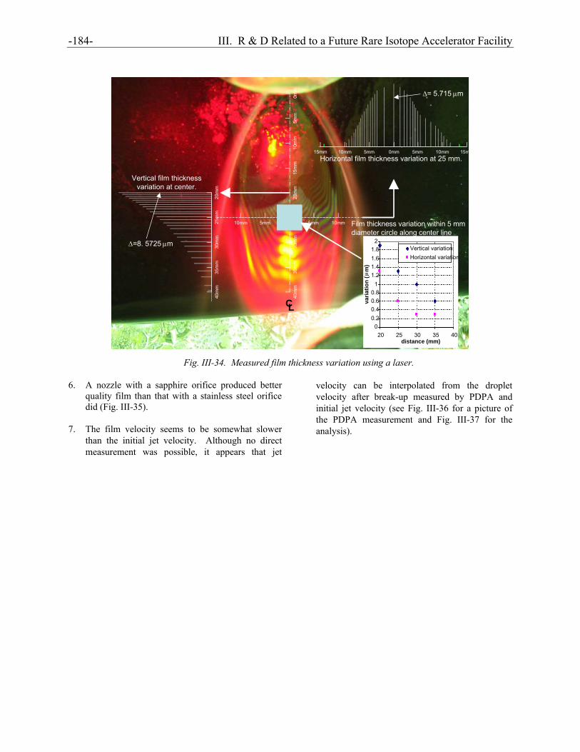
diameter of 0.25 mm (10 mils) – 0.5 mm (20 mils) appear to be the most suitable range to produce the best looking stable film for both water and FC-3283 (see Fig. III-32). A film produced using the 0.5 mm nozzle showed that the variation in film thickness within the expected beam diameter of 5 mm on the film is < 1 µm (see Figs. III-33 and III-34). A film produced by a jet issuing from the large diameter nozzle (1.0 mm = 40 mils) appears wavy at almost all conditions and is not suitable for the stripper.
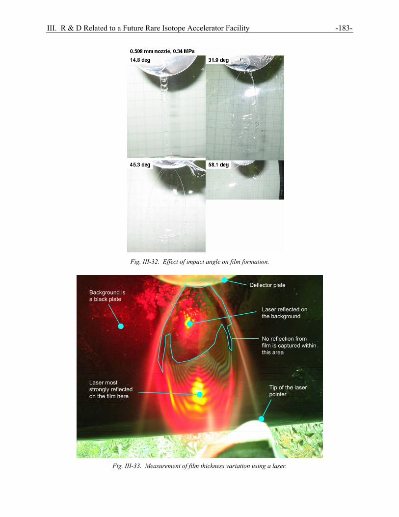
III. R & D Related to a Future Rare Isotope Accelerator Facility -183-
Fig. III-32. Effect of impact angle on film formation.
Background isa black plate
Deflector plate
Laser reflected onthe background
No reflection fromfilm is captured withinthis area
Tip of the laserpointer
Laser moststrongly reflectedon the film here
Fig. III-33. Measurement of film thickness variation using a laser.
-184- III. R & D Related to a Future Rare Isotope Accelerator Facility
Horizontal film thickness variation at 25 mm.
∆= 5.715 µm
Vertical film thicknessvariation at center.
∆=8. 5725 µm
Film thickness variation within 5 mmdiameter circle along center line
0mm 5mm 10mm 15mm5mm10mm15mm
35m
m40
mm
30m
m25
mm
20m
m
35m
m40
mm
30m
m25
mm
20m
m10
mm
15m
m5m
m0m
m
CL
5mm 10mm5mm10mm
00.20.40.60.8
11.21.41.61.8
2
20 25 30 35 40distance (mm)
varia
tion
(µm
)
Vertical variationHorizontal variation
Fig. III-34. Measured film thickness variation using a laser.
6. A nozzle with a sapphire orifice produced better quality film than that with a stainless steel orifice did (Fig. III-35).
7. The film velocity seems to be somewhat slower than the initial jet velocity. Although no direct measurement was possible, it appears that jet
velocity can be interpolated from the droplet velocity after break-up measured by PDPA and initial jet velocity (see Fig. III-36 for a picture of the PDPA measurement and Fig. III-37 for the analysis).

III. R & D Related to a Future Rare Isotope Accelerator Facility -185-
0.5 mm nozzle, 0.17 MPa at nozzle
Sapphire orifice All stainless steel
Photos taken at: exp. time = 10 sec,F = 4.8, focal dist. = 20 cm
Blurry interference pattern onthe film shows the filmÕsprofile moved.
Fig. III-35. Interference patterns on films produced by a sapphire orifice and all stainless steel nozzles.
Fig. III-36. Velocity measurement using PDPA.
8. The stability diagrams represented as a
function of Re and We numbers for water and FC-3283 seem to be very similar, indicating its universal nature (Fig. III-38).

-186- III. R & D Related to a Future Rare Isotope Accelerator Facility
40
Fig. III-37. Measured droplets velocity after break-up.
Fig. III-38. Experimentally developed stability diagram. Figure III-38 shows that threshold data (velocity below which no film formation was observed) for both water and FC-3283 form a single, relatively narrow band in Re-We space, indicating the stability
boundary above which film formation is expected (green shaded region in Fig. III-38) and this stability boundary appears to be universal. Values for velocity and thickness in Fig. III-38 are for Li. This figure suggests that a Li
0
5
10
15
20
2Velocity (m/s)
5
30
35
0 5 10 15 20 25 30 35 40Distance from deflector (mm)
0.34 MPa0.254 mm nozzle, 45 deg incident angle 0.69 MPa1.03 MPa1.72 MPa
* Velocity at 0 mm = initial jet velocity

III. R & D Related to a Future Rare Isotope Accelerator Facility -187- film of ~4 µm thick at ≿100 - 150 m/s would be stable. The same data presented in Fig. III-38 are also plotted in the film velocity-film thickness space (Fig. III-39). This figure shows that for the same set of Re and We, the difference in physical parameters for FC-3283 and water is approximately the same as
that for water and lithium. For the same Re and We, no apparent differences in film behavior were observed between FC-3283 and water films, suggesting insignificant difference in film behavior between water and Li films is expected, if any.
1.E-07
1.E-06
1.E-05
1.E-04
1.E-03
1.E-02
1 10 100 1000
Film velocity, U (m/s)
Film
thic
knes
s,
t (m
)
Water dataFC3283 dataFC3283
H2OLi
0.4 µm
40 µm
100
m/s
200
m/s
Area indicating same Re -We region
Fig. III-39. Thickness of various demonstrated thin films as a function of film velocity. To summarize this phase of study, as the linear stability theory suggests, the films of different fluids appear to behave in a similar manner when their Re and We are kept the same. Although larger nozzle size is better to avoid potential plugging, it was found that a nozzle diameter of ~0.5 mm may be the largest size to form a nice film. Also to form a stable Li thin
film, a Li jet needs to be issued at ≿100 - 150 m/s (corresponding a driving pressure of 3 – 6 MPa). The angle of incidence should be between 30 – 45 degrees and the relative position of the nozzle to the deflector must be adjustable with a resolution of ~ 0.1 mm (Fig. III-40).
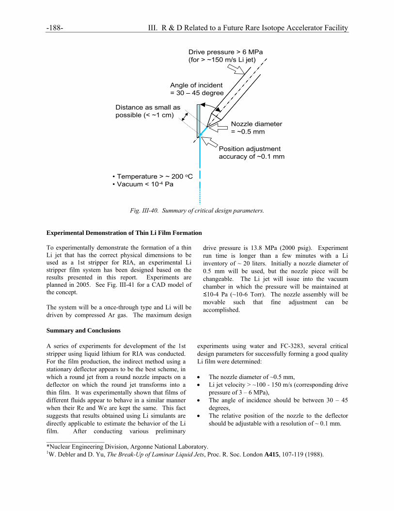
-188- III. R & D Related to a Future Rare Isotope Accelerator Facility
Nozzle diameter = ~0.5 mm
Angle of incident = 30 – 45 degree
Distance as small as possible (< ~1 cm)
Position adjustmentaccuracy of ~0.1 mm
• Temperature > ~ 200 oC• Vacuum < 10-4 Pa
Drive pressure > 6 MPa (for > ~150 m/s Li jet)
Fig. III-40. Summary of critical design parameters. Experimental Demonstration of Thin Li Film Formation To experimentally demonstrate the formation of a thin Li jet that has the correct physical dimensions to be used as a 1st stripper for RIA, an experimental Li stripper film system has been designed based on the results presented in this report. Experiments are planned in 2005. See Fig. III-41 for a CAD model of the concept. The system will be a once-through type and Li will be driven by compressed Ar gas. The maximum design
drive pressure is 13.8 MPa (2000 psig). Experiment run time is longer than a few minutes with a Li inventory of ~ 20 liters. Initially a nozzle diameter of 0.5 mm will be used, but the nozzle piece will be changeable. The Li jet will issue into the vacuum chamber in which the pressure will be maintained at ≾10-4 Pa (~10-6 Torr). The nozzle assembly will be movable such that fine adjustment can be accomplished.
Summary and Conclusions A series of experiments for development of the 1st stripper using liquid lithium for RIA was conducted. For the film production, the indirect method using a stationary deflector appears to be the best scheme, in which a round jet from a round nozzle impacts on a deflector on which the round jet transforms into a thin film. It was experimentally shown that films of different fluids appear to behave in a similar manner when their Re and We are kept the same. This fact suggests that results obtained using Li simulants are directly applicable to estimate the behavior of the Li film. After conducting various preliminary
experiments using water and FC-3283, several critical design parameters for successfully forming a good quality Li film were determined: • The nozzle diameter of ~0.5 mm, • Li jet velocity > ~100 - 150 m/s (corresponding drive
pressure of 3 – 6 MPa), • The angle of incidence should be between 30 – 45
degrees, • The relative position of the nozzle to the deflector
should be adjustable with a resolution of ~ 0.1 mm.
__________________ *Nuclear Engineering Division, Argonne National Laboratory. 1W. Debler and D. Yu, The Break-Up of Laminar Liquid Jets, Proc. R. Soc. London A415, 107-119 (1988).

III. R & D Related to a Future Rare Isotope Accelerator Facility -189- 2S. J. Leib and M. E. Goldstein, Convective and Absolute Instability of a Visous Liquid Jet, Phys. Fluids 29(4), 952-954 (1986). 3S. P. Lin and R. D. Reitz, Drop and Spray Formation from a Liquid Jet, Annual Review of Fluid Mechanics 30, 85-105 (1998). 4S. P. Lin, M. Hudman, and J. N. Chen, Absolute and Convective Instability of a Liquid Jet, Proceedings of the Fourth Microgravity Fluid Physics & Transport Phenomena Conference, August 12-14, 1998, Cleveland, OH, pp. 534-538, (1999). 5Y. Momozaki, Development of an Electron Stripper Using Thin Liquid Lithium Film for Rare Isotope Accelerator, unpublished (2004).
Fig. III-41. CAD model of the thin lithium jet apparatus concept.

-190- III. R & D Related to a Future Rare Isotope Accelerator Facility