ignition system
DESCRIPTION
AutomotiveTRANSCRIPT
Chapter 3: Electronic Engine Management Systems
The Crankshaft Position Sensor
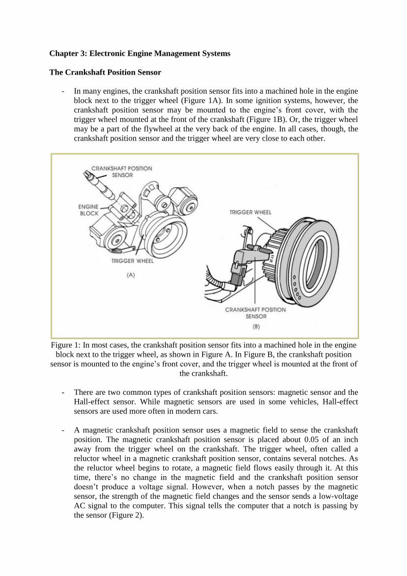
- In many engines, the crankshaft position sensor fits into a machined hole in the engine
block next to the trigger wheel (Figure 1A). In some ignition systems, however, the
crankshaft position sensor may be mounted to the engine’s front cover, with the
trigger wheel mounted at the front of the crankshaft (Figure 1B). Or, the trigger wheel
may be a part of the flywheel at the very back of the engine. In all cases, though, the
crankshaft position sensor and the trigger wheel are very close to each other.
Figure 1: In most cases, the crankshaft position sensor fits into a machined hole in the engine
block next to the trigger wheel, as shown in Figure A. In Figure B, the crankshaft position
sensor is mounted to the engine’s front cover, and the trigger wheel is mounted at the front of
the crankshaft.
- There are two common types of crankshaft position sensors: magnetic sensor and the
Hall-effect sensor. While magnetic sensors are used in some vehicles, Hall-effect
sensors are used more often in modern cars.
- A magnetic crankshaft position sensor uses a magnetic field to sense the crankshaft
position. The magnetic crankshaft position sensor is placed about 0.05 of an inch
away from the trigger wheel on the crankshaft. The trigger wheel, often called a
reluctor wheel in a magnetic crankshaft position sensor, contains several notches. As
the reluctor wheel begins to rotate, a magnetic field flows easily through it. At this
time, there’s no change in the magnetic field and the crankshaft position sensor
doesn’t produce a voltage signal. However, when a notch passes by the magnetic
sensor, the strength of the magnetic field changes and the sensor sends a low-voltage
AC signal to the computer. This signal tells the computer that a notch is passing by
the sensor (Figure 2).

- Hall-effect crankshaft position sensors work in much the same way as magnetic
sensors; however, instead of sending a low-voltage AC signal to the computer, the
Hall-effect sensor sends a pulse signal. An interrupter ring is placed on the crankshaft
pulley as shown in Figure 3A. The ring contains three equally spaced blades. As the
crankshaft rotates, the blades on the interrupter ring pass through the Hall-effect
switch to trigger the crankshaft position sensor. Therefore, each time a blade passes
through the Hall-effect sensor, the sensor sends a voltage pulse to the computer
system. These pulses are usually called square waves, because they look like a series
of small squares as shown in Figure 3B.
Figure 2: When a reluctor wheel notch passes by the magnetic crankshaft position sensor, the
strength of the magnetic field changes and the sensor sends a low-voltage AC signal to the
computer. (Courtesy of General Motors Corp)
Figure 3: In a Hall-effect crankshaft position sensor, one or more interrupter rings is placed
on the crankshaft as shown in Figure A. When a Hall-effect crankshaft position sensor sends
a voltage pulse to the computer, these voltage pulses produce a signal pattern called a square
wave, as shown in Figure B.

The Trigger Wheel
- A wide variety of different trigger wheels are used in direct-fire ignition systems.
Some wheels have notches cut into their edges, while others may use holes or slits to
trigger the crankshaft position sensor.
- Figure 4 shows a typical trigger wheel for a six-cylinder engine. The wheel contains
six equally spaced notches around its edge — one notch for each 60 degrees of
crankshaft rotation. Each time one of the notches rotates by the crankshaft position
sensor, the sensor sends a signal to the vehicle’s computer. In this way, the computer
always knows the current crankshaft position.
Figure 4: The trigger wheel for a six-cylinder engine contains six crankshaft position notches
in its edge, one for each 60 degrees of crankshaft rotation. The wheel also contains a seventh
notch called a synch notch. The synch notch is used to determine the starting point for the
cylinder firing order.
- Note that the trigger wheel in Figure 4 also contains a seventh notch that’s very close
to one of the crankshaft position notches. This extra notch is called a synch notch. The
synch notch is used to help the computer identify the starting point in the firing order.
In other words, when the synch notch passes by the crankshaft position sensor, it
gives the computer a point of reference to help identify the engine cylinders. Once the
computer determines the location of one cylinder in relation to the notches on the
trigger wheel, the computer can determine the positions of the other cylinders.
- Each time a notch passes by the crankshaft position, a signal is sent to the computer.
The spaces between the six regular notches are equal. However, when the synch notch

passes by the crankshaft position sensor, another notch passes almost immediately
after it. So, when the computer receives two signals very close together, it knows that
the synch notch has just passed by the crankshaft position sensor. The computer then
begins counting the crankshaft position signals from that point. In this way, the
computer can tell which cylinder is ready to be fired.
- In addition to counting the signals sent by the crankshaft position sensor, the
computer measures the amount of time between each signal. The computer can use
this information to determine the engine speed. For instance, the computer knows that
when the time between pulses is long, the engine is running slow, and when the time
between pulses is very short, the engine is running fast.
- In systems that use a synch notch, the computer can also use the time between pulses
to identify the synch notch. Remember that the synch notch is located very close to
another crankshaft position notch. When the computer measures a very short time
between two signals, it knows that the second signal is for the synch notch.
- Many different types of trigger wheels are used by different manufacturers. The
trigger wheel shown in Figure 5 has notches all the way around its edge. In this
trigger wheel, each notch represents a certain amount of crankshaft rotation. The
crankshaft position trigger points are indicated by areas of missing teeth in the wheel.
- In a similar type of trigger wheel, the crankshaft position trigger points are indicated
by areas where the notches are placed closer together. Still another type of trigger
wheel is a plate that contains a series of slots in its outer edge. The plate is then bolted
to the rear of the crankshaft near the transmission (Figure 6). Since this wheel is
bolted directly to the rear of the crankshaft, the wheel rotates with the crankshaft as
the engine operates. In this design, the crankshaft position sensor detects whenever
one of the slots passes by, and indicates the current crankshaft position.
Figure 5: In this trigger wheel design, notches are placed all the way around the edge of the
wheel. The crankshaft position trigger points are indicated by areas of missing teeth on the
wheel.

Figure 6: Another type of trigger wheel uses a series of slots placed in the outer edge of a
plate that’s bolted to the rear of the crankshaft, as shown here. (Courtesy of Chrysler
Corporation)
- As shown, the exact design of the trigger wheel varies, depending on the engine make
and model. However, all trigger wheels operate in the same basic way. All trigger
wheels are designed to rotate with the crankshaft, and the notches or holes in the
trigger wheel indicate the crankshaft position to the crankshaft position sensor.
The Camshaft Position Sensor
- Some direct-fire ignition systems use a synch notch on the trigger wheel to help the
computer identify which cylinder is ready to fire. However, some systems use an
additional sensor called a camshaft position sensor instead of a synch notch to
perform this function.
- In this type of system, the camshaft position sensor sends a signal to the computer to
indicate that a particular cylinder is ready to be fired.
- A typical camshaft position sensor is shown in Figure 7A. In most cases, the camshaft
position sensor is mounted in the engine’s front cover, next to the camshaft gear as
shown in Figure 7B. A notched wheel is mounted on the camshaft gear. As the
camshaft rotates, the notches on the wheel cause the camshaft position sensor to
signal the computer. This signal is used to identify the notches so that the computer
can keep track of them. Once the computer knows the location of one notch, it can
count the number of signals from that point to determine the current camshaft position.
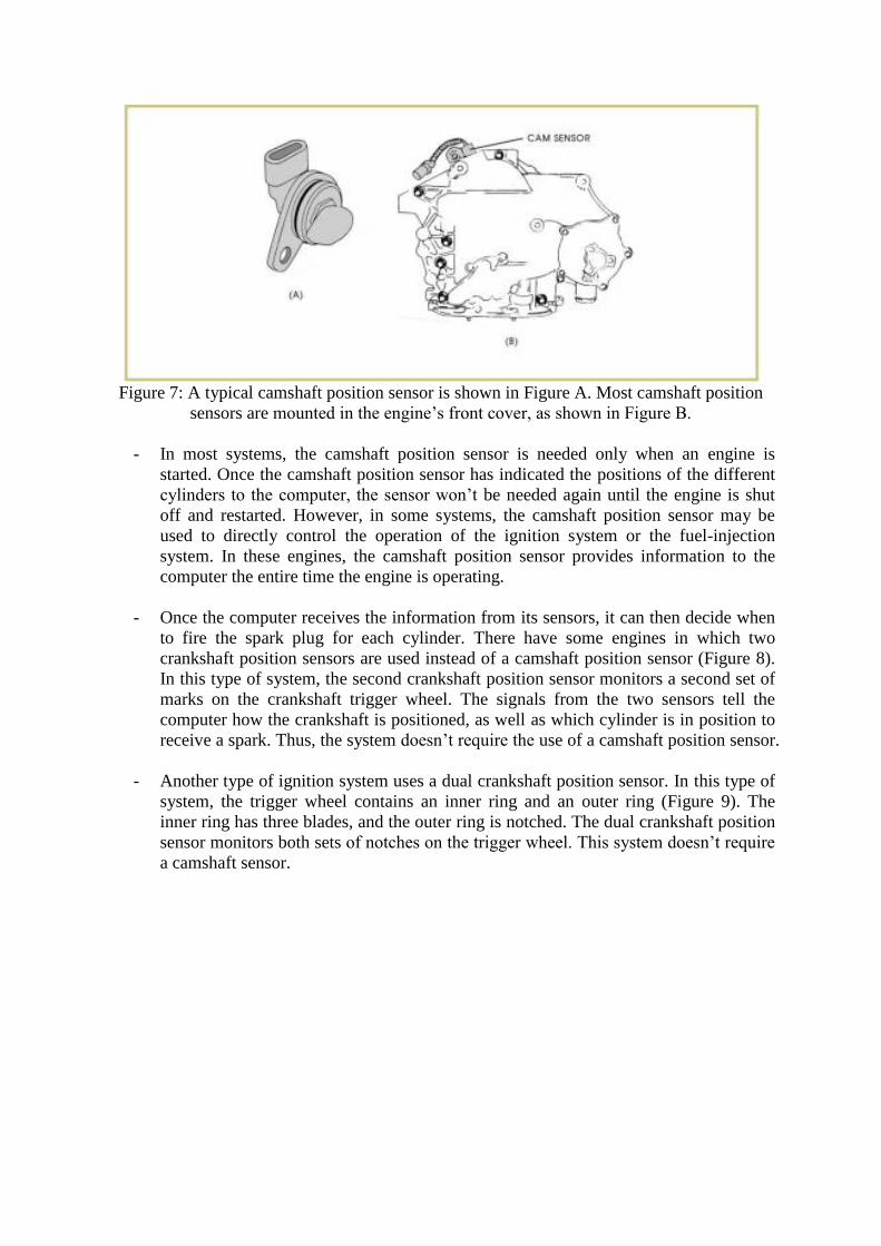
Figure 7: A typical camshaft position sensor is shown in Figure A. Most camshaft position
sensors are mounted in the engine’s front cover, as shown in Figure B.
- In most systems, the camshaft position sensor is needed only when an engine is
started. Once the camshaft position sensor has indicated the positions of the different
cylinders to the computer, the sensor won’t be needed again until the engine is shut
off and restarted. However, in some systems, the camshaft position sensor may be
used to directly control the operation of the ignition system or the fuel-injection
system. In these engines, the camshaft position sensor provides information to the
computer the entire time the engine is operating.
- Once the computer receives the information from its sensors, it can then decide when
to fire the spark plug for each cylinder. There have some engines in which two
crankshaft position sensors are used instead of a camshaft position sensor (Figure 8).
In this type of system, the second crankshaft position sensor monitors a second set of
marks on the crankshaft trigger wheel. The signals from the two sensors tell the
computer how the crankshaft is positioned, as well as which cylinder is in position to
receive a spark. Thus, the system doesn’t require the use of a camshaft position sensor.
- Another type of ignition system uses a dual crankshaft position sensor. In this type of
system, the trigger wheel contains an inner ring and an outer ring (Figure 9). The
inner ring has three blades, and the outer ring is notched. The dual crankshaft position
sensor monitors both sets of notches on the trigger wheel. This system doesn’t require
a camshaft sensor.
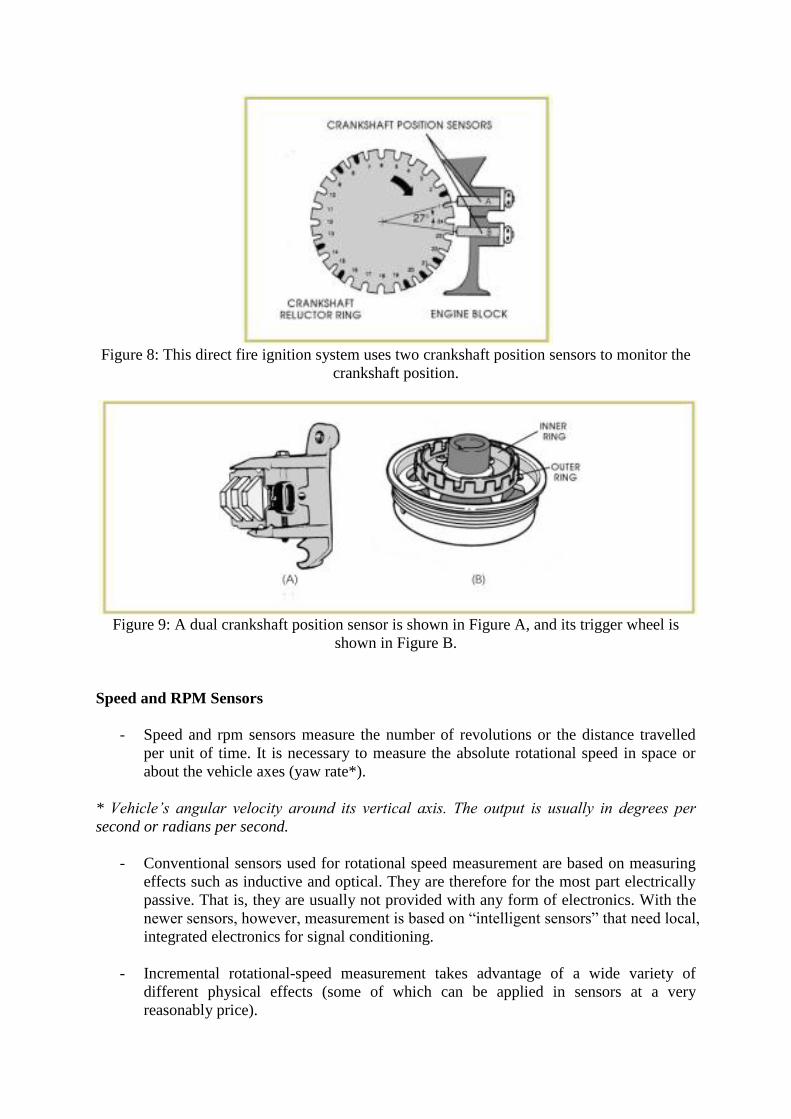
Figure 8: This direct fire ignition system uses two crankshaft position sensors to monitor the
crankshaft position.
Figure 9: A dual crankshaft position sensor is shown in Figure A, and its trigger wheel is
shown in Figure B.
Speed and RPM Sensors
- Speed and rpm sensors measure the number of revolutions or the distance travelled
per unit of time. It is necessary to measure the absolute rotational speed in space or
about the vehicle axes (yaw rate*).
* Vehicle’s angular velocity around its vertical axis. The output is usually in degrees per
second or radians per second.
- Conventional sensors used for rotational speed measurement are based on measuring
effects such as inductive and optical. They are therefore for the most part electrically
passive. That is, they are usually not provided with any form of electronics. With the
newer sensors, however, measurement is based on “intelligent sensors” that need local,
integrated electronics for signal conditioning.
- Incremental rotational-speed measurement takes advantage of a wide variety of
different physical effects (some of which can be applied in sensors at a very
reasonably price).

- Optical and capacitive sensors are highly unsuitable for the rough operating
conditions encountered in the motor vehicle. Here, magnetic effect sensors are used
almost exclusively.
- The examples of relative rotational speed are as follows:
o Crankshaft and camshaft rotational speed
o Wheel speeds (for ABS/ TCS/ ESP)
o Rotational speed of the diesel fuel injection pump
- In the detection of relative yaw rate, depending upon the number and size of the
scanned rotational rotor markings, a distinction is made between the following types
of sensor:
o Increment sensor with closely spaced rotational markings. Up to a certain
point, this form of sensor permits instantaneous speed to be measured at points
on the circumference, or the registration of very fine angular divisions.
o Segment sensors, with only a small number of scanned rotational segments
(for example, equivalent to the number of engine cylinders).
o Simple speed sensor, with only a single scanned marking per revolution, so
that only the average rotational speed can be recorded.
Figure 10: Determination of the rotational speed (rotor form): Incremental sensor, segment
sensor, speed sensor
Timing Control in Direct-fire Systems
- The computer system used on a particular car may be given a special name by the
manufacturer, such as the electronic control module (ECM) or ignition control module
(ICM). However, in general, the computer system is simply a small computer that
controls many vehicle functions.
- As learned before, the spark must occur sooner in the compression stroke as an
engine’s speed increases. However, the engine speed isn’t the only factor that
influences spark timing. The load placed on the engine, external air temperature,
engine temperature, and air pressure also affect the spark timing. In order to
accurately track current engine conditions, therefore, the computer system gathers
information from a number of different sensors mounted in the engine. These sensors
measure the engine temperature, speed of the car, outside air temperature, amount of
vacuum in the intake manifold, amount of air entering the engine, and many other
factors.
- The computer system analyzes the information from all the sensors and then
determines the best time for the spark to occur under the current engine conditions.
The computer system continually monitors all of these factors as the car is running,
and continuously changes the ignition timing to best match the current conditions.
- In addition, many vehicles use sensors to help the computer system control the spark
under certain conditions. For example, a condition called spark knock or detonation
can occur in an engine when the air-and-fuel mixture in a cylinder explodes rather
than burns. These explosions may occur when the engine temperature rises, or when
an incorrect air-and-fuel mixture is used in an engine. The explosions are usually loud
enough for the driver to hear, and sound like a tapping or knocking noise coming from
inside the engine.
- Spark knock usually happens when an engine is placed under a heavy load, such as
when it’s pulling a trailer or going up a steep hill. Under these conditions, the mixture
in the cylinder can explode and can actually start to burn in several areas of the
combustion chamber at the same time.
- As the exploding fuel smashes into the top of the piston, it causes a shock wave to
flow through the cylinder. In most cases, the fuel explodes so quickly that the piston
may not even reach TDC before the pressure from the explosion forces it back down.
The forces of detonation can be strong enough to cause damage to the pistons and
piston rings.
- One way to control detonation is to reduce the amount of ignition timing advance
under those conditions. Therefore, to help determine when these conditions occur,
some ignition systems use special sensors called antiknock sensors. An antiknock
sensor is usually mounted in the engine block. When detonation occurs, the knocking
noise causes the antiknock sensor to send a signal to the computer system.
- The computer system can then retard the ignition timing until the knocking stops. By
using an antiknock sensor, the computer control system can help to prevent detonation
damage.
- An automotive computer control system has many capabilities. The computer must
continually make decisions about ignition timing as the engine is running — many
times per second. By continually adjusting the ignition timing to match current engine
conditions, the computer helps the engine perform better, consume less fuel, and
produce fewer harmful exhaust emissions.
*note: References from technical support articles:
http://www.autoshop101.com/autoshop15.html