iglide g300 - igus® inc. · 0 3,625 7,250 10,875 14,500 3 4 5 6 7 8 9 10 ... v = 1.96 fpm...
TRANSCRIPT

iglide® G300
• Over 650 sizes available from stock
• High wear resistance
• Resistance to dust and dirt
• Economic
• Self-lubricating and maintenance free
83

Maintenance-free, dry running
High wear resistance
Resistant to dirt and dust
Cost-effective
84
iglide®
G300 iglide® G300 - General PurposeMost popular iglide® material worldwide
l When you need an economical all-around performance bearing
l For low to average surface speedsl When the bearing needs to run on different shaft
materialsl For oscillating and rotating movements
l When mechanical reaming of the wall surface is necessary
➤ iglide® M250l When the highest wear resistance is necessary ➤ iglide® L280l When universal chemical resistance is required ➤ iglide® T500l If temperatures are constantly greater than +266°F ➤ iglide® T500, H, H370l For underwater use ➤ iglide® H370
iglide® G300 bearings cover an extremely wide range of different requirements. Typical applications include medium to high loads, medium sliding speeds and medium temperatures. Typical applications include medium to high loads, medium sliding speeds and medium temperatures.
max. +266°Fmin. –40°FF
Available from stock Detailed information about delivery time online.
lAgricultural machineslMachine buildinglSports and leisurelAutomotive
lMechatronicslConstruction
machinery
Ø 1.5 to 150 mmmore dimensions on requestmm
Typical application areas
Ø 1/8 to 3 inchesmore dimensions on request
Price breaks online No minimum order.$
Lifetime calculation, configuration and more ➤ www.igus.com/g300
iglide®
G300
853D-CAD files, prices and delivery time ➤ www.igus.com/g300
iglide® G300 - Technical Data
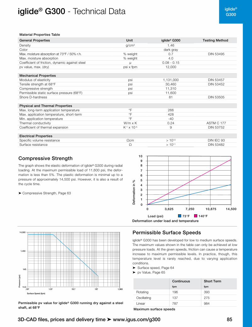
Compressive StrengthThe graph shows the elastic deformation of iglide® G300 during radial loading. At the maximum permissible load of 11,600 psi, the defor-mation is less than 5%. The plastic deformation is minimal up to a pressure of approximately 14,500 psi. However, it is also a result of the cycle time.
➤ Compressive Strength, Page 63
Deformation under load and temperatureLoad (psi) 73°F 140°F
Def
orm
atio
n in
%
0
12
0 3,625 7,250 10,875 14,500
3
4
5
6
7
89
10
1,96919719.7.19714.5
1,450
14,500
145
1.97
Pre
ssu
re (p
si)
Surface Speed (fpm)
Permissible pv value for iglide® G300 running dry against a steel shaft, at 68°F
Continuous Short Term
fpm fpm
Rotating 196 393
Oscillating 137 275
Linear 787 984
Maximum surface speeds
Permissible Surface Speedsiglide® G300 has been developed for low to medium surface speeds. The maximum values shown in the table can only be achieved at low pressure loads. At the given speeds, friction can cause a temperature increase to maximum permissible levels. In practice, though, this temperature level is rarely reached, due to varying application conditions.➤ Surface speed, Page 64➤ pv Value, Page 65
Material Properties Table
General Properties Unit iglide® G300 Testing MethodDensity g/cm3 1.46Color dark grayMax. moisture absorption at 73°F / 50% r.h. % weight 0.7 DIN 53495Max. moisture absorption % weight 4.0Coefficient of friction, dynamic against steel µ 0.08 - 0.15pv value, max. (dry) psi x fpm 12,000
Mechanical PropertiesModulus of elasticity psi 1,131,000 DIN 53457Tensile strength at 68°F psi 30,460 DIN 53452Compressive strength psi 11,310Permissible static surface pressure (68°F) psi 11,600Shore D-hardness 81 DIN 53505
Physical and Thermal PropertiesMax. long-term application temperature °F 266Max. application temperature, short-term °F 428Min. application temperature °F -40Thermal conductivity W/m x K 0.24 ASTM C 177Coefficient of thermal expansion K-1 x 10⁻⁵ 9 DIN 53752
Electrical PropertiesSpecific volume resistance Ωcm > 1013 DIN IEC 93Surface resistance Ω > 1011 DIN 53482

86
iglide®
G300
Lifetime calculation, configuration and more ➤ www.igus.com/g300
iglide® G300 - Technical Data
Surface Speed (fpm)
Coe
�ci
ent o
f fric
tion
(µ)
9.84 19.69 29.53 39.37 49.22 59.06 68.90
0.1
0.2
0.3
0.4
0.5
Coefficient of friction of iglide® G300 as a result of the running speed; p = 108 psi
Coefficient of friction for iglide® G300 against steel (Shaft finish = 40 rms, 50 HRC)
Pressure (psi)
Coe
�ci
ent
of fr
ictio
n µ
0 1,450 2,901 4,351 5,801 7,252 8,702 10,150 11,6000.00
0.05
0.10
0.15
0.20
0.25
0.30
0.35
Shaft Roughness (rms)
Co
e�
cie
nt
of
Fri
cti
on
µ
0
0.1
0.2
0.3
0.4
0.5
0 20 40 60 80
Coefficient of friction of iglide® G300 as a result of the load, v = 1.96 fpm
Coefficient of friction as result of the shaft surface (Shaft - 1050 hard chromed)
Friction and WearSimilar to wear resistance, the coefficient of friction μ also changes with the load. The coefficient of friction decreases with increasing loads, whereas an increase in surface speed causes an increase of the coefficient of friction. This relationship explains the excellent results of iglide® G300 plain bearings for high loads and low speeds.The friction and wear are also dependent, to a large degree, on the shaft partner. Shafts that are too smooth, increase both the coefficient of friction and the wear of the bearing. For iglide® G300, a ground surface with an average roughness Ra= 32 rms is recommended.
➤ Coefficients of friction and surfaces, Page 68 ➤ Wear Resistance, Page 69
Temperature limits for iglide® G300
TemperaturesApplication temperatures affect the properties of plain bearings greatly. The short-term maximum temperature is 428°F, this allows the use of iglide® G300 plain bearings in heat treating applications in which the bearings are not subjected to additional loading.
With increasing temperatures, the compressive strength of iglide® G300 plain bearings decreases. The graph shows this inverse relationship. However, at the long-term maximum temperature of 266°F, the permissible surface pressure is still above 5,800 psi.The ambient temperatures that are prevalent in applications also has an effect on the bearing wear. With increasing temperatures, the wear increases and this effect is notable starting at the temperature of 248°F.
➤ Application temperatures, Page 67
68 122 176 248 2660
2901
5802
8702
11,600
17,400
14,500
86 104 140 158 194 212 230
Pre
ssu
re (
psi
)
Temperature in (°F)
Recommended maximum permissible static surface pressure of iglide® G300 as a result of temperature
iglide® G300 Application Temperature
Minimum - 40°F
Max. long-term +266°F
Max. short-term +428°F
Additional axial securing +176°F
iglide® G300 Coefficient of Friction
Dry 0.08 - 0.15
Grease 0.09
Oil 0.04
Water 0.04
iglide®
G300
873D-CAD files, prices and delivery time ➤ www.igus.com/g300
iglide® G300 - Technical Data
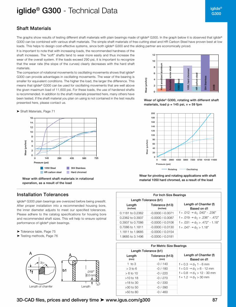
Shaft Materials
The graphs show results of testing different shaft materials with plain bearings made of iglide® G300. In the graph below it is observed that iglide® G300 can be combined with various shaft materials. The simple shaft materials of free-cutting steel and HR Carbon Steel have proven best at low loads. This helps to design cost-effective systems, since both iglide® G300 and the sliding partner are economically priced.
Wear of iglide® G300, rotating with different shaft materials, load p = 145 psi, v = 59 fpm
2
4
8
10
12
0
6
Har
d a
nod
ized
alu
min
um
Aut
omat
ic s
crew
ste
el
1050
Ste
el
1050
, har
d c
hrom
ed
HR
car
bon
ste
el
304
Sta
inle
ss
440B
Wea
r (µ
m/k
m)
0
2
4
6
8
12
10
16
14
7255804352901450
Pressure (psi)
Wea
r (µ
m/k
m)
1050 Steel 304 Stainless
HR carbon steel Hard chromed
We
ar
(µm
/km
)
Pressure (psi)
0
20
40
60
80
100
120
140
160
180
200
0 1450 2900 4350 5800 7250 8700 10150 11600
Rotating Oscillating
Wear for pivoting and rotating applications with shaft material 1050 hard chromed, as a result of the loadWear with different shaft materials in rotational
operation, as a result of the load
It is important to note that with increasing loads, the recommended hardness of the shaft increases. The “soft” shafts tend to wear more easily and thus increase the wear of the overall system. If the loads exceed 290 psi, it is important to recognize that the wear rate (the slope of the curves) clearly decreases with the hard shaft materials.The comparison of rotational movements to oscillating movements shows that iglide® G300 can provide advantages in oscillating movements. The wear of the bearing is smaller for equivalent conditions. The higher the load, the larger the difference. This means that iglide® G300 can be used for oscillating movements that are well above the given maximum load of 11,600 psi. For these loads, the use of hardened shafts is recommended. In addition to the shaft materials presented here, many others have been tested. If the shaft material you plan on using is not contained in the test results presented here, please contact us.
➤ Shaft Materials, Page 71
Installation Tolerancesiglide® G300 plain bearings are oversized before being pressfit. After proper installation into a recommended housing bore, the inner diameter adjusts to meet our specified tolerances. Please adhere to the catalog specifications for housing bore and recommended shaft sizes. This will help to ensure optimal performance of iglide® plain bearings.
➤ Tolerance table, Page 75 ➤ Testing methods, Page 76
.0197”(0.5 mm)
b1
A
30°
f
A
Length of chamfer Length30°
For Inch Size Bearings
Length Tolerance (b1)Length of Chamfer (f)
Based on d1Length(inches)
Tolerance (h13)(inches)
0.1181 to 0.2362 -0.0000 /-0.0071 f = .012 ➝ d1 .040” - .236”
f = .019 ➝ d1 > .236” - .472”
f = .031 ➝ d1 > .472” - 1.18”
f = .047 ➝ d1 > 1.18”
0.2362 to 0.3937 -0.0000 /-0.00870.3937 to 0.7086 -0.0000 /-0.01060.7086 to 1.1811 -0.0000 /-0.01301.1811 to 1.9685 -0.0000 /-0.01541.9685 to 3.1496 -0.0000 /-0.0181
For Metric Size Bearings
Length Tolerance (b1)Length of Chamfer (f)
Based on d1Length
(mm)Tolerance (h13)
(mm)
1 to 3 -0 /-140 f = 0.3 ➝ d1 1 - 6 mmf = 0.5 ➝ d1 > 6 - 12 mmf = 0.8 ➝ d1 > 12 - 30 mmf = 1.2 ➝ d1 > 30 mm
> 3 to 6 -0 /-180> 6 to 10 -0 /-220>10 to 18 -0 /-270>18 to 30 -0 /-330>30 to 50 -0 /-390>50 to 80 -0 /-460
88
iglide®
G300
Lifetime calculation, configuration and more ➤ www.igus.com/g300
iglide® G300 - Technical Data
Radiation Resistance
Plain bearings made from iglide® G300 are resistant to radiation up to an intensity of 3 x 10² Gy.
UV-Resistance
iglide® G300 plain bearings are permanently resistant to UV-radiation.
Vacuum
iglide® G300 plain bearings outgas in a vacuum. Use in a vacuum environment is only possible for dehumidified bearings.
Electrical Properties
iglide® G300 plain bearings are electrically insulating.
iglide® G300
Specific volume resistance > 1013 Ωcm
Surface resistance > 1011 Ω
Electrical properties of iglide® G300
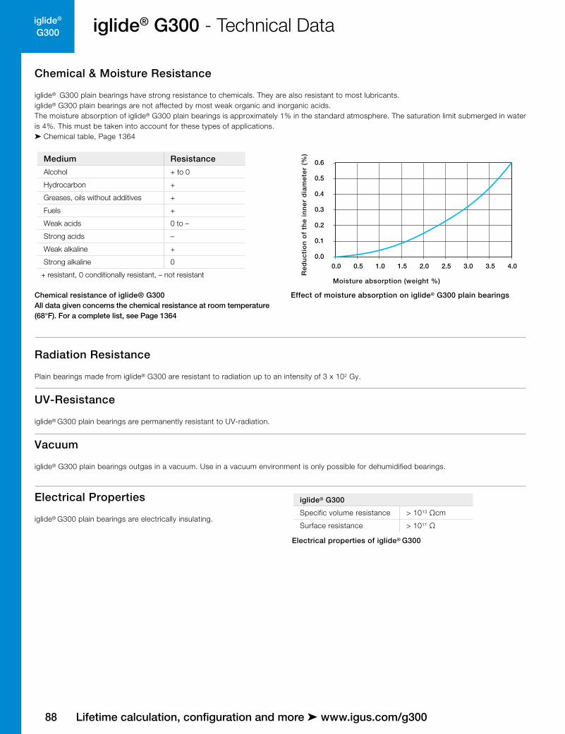
Chemical & Moisture Resistance
iglide® G300 plain bearings have strong resistance to chemicals. They are also resistant to most lubricants.iglide® G300 plain bearings are not affected by most weak organic and inorganic acids.The moisture absorption of iglide® G300 plain bearings is approximately 1% in the standard atmosphere. The saturation limit submerged in water is 4%. This must be taken into account for these types of applications.➤ Chemical table, Page 1364
Medium Resistance
Alcohol + to 0
Hydrocarbon +
Greases, oils without additives +
Fuels +
Weak acids 0 to –
Strong acids –
Weak alkaline +
Strong alkaline 0
+ resistant, 0 conditionally resistant, – not resistant
Chemical resistance of iglide® G300All data given concerns the chemical resistance at room temperature (68°F). For a complete list, see Page 1364
Effect of moisture absorption on iglide® G300 plain bearingsR
ed
uc
tio
n o
f th
e i
nn
er
dia
me
ter
(%)
Moisture absorption (weight %)
0.0 0.5 1.0 1.5 2.0 2.5 3.0 3.5 4.00.0
0.1
0.2
0.3
0.4
0.5
0.6

iglide®
G300
89
iglide® G300 - Product RangeSleeve bearing - Inch
Type Dimensions
G S I -01 03-02
iglid
e® m
ater
ial
Form
S (s
leev
e)
Inch
Inne
r-Ø
d1
(inch
)
Out
er-Ø
d2
(inch
)
Leng
th b
1 (in
ch)
Order key
.0197b1
d1
d2A
30°
f
A
30° For tolerance values please refer to page 87
*Based on steel housing bore
3D-CAD files, prices and delivery time ➤ www.igus.com/g300
Part Number d1 d2 b1 I.D. After Pressfit* Housing Bore Shaft Size
Min. Max. Min. Max. Min. Max.
GSI-0203-03 1/8 3/16 3/16
.1251 .1269
.1873 .1878 .1236 .1243
GSI-0203-04 1/8 3/16 1/4 .1873 .1878 .1236 .1243
GSI-0203-06 1/8 3/16 3/8 .1873 .1878 .1236 .1243
GSI-0304-04 3/16 1/4 1/4
.1873 .1892
.2497 .2503 .1858 .1865
GSI-0304-06 3/16 1/4 3/8 .2497 .2503 .1858 .1865
GSI-0304-08 3/16 1/4 1/2 .2497 .2503 .1858 .1865
GSI-0405-04 1/4 5/16 1/4
.2498 .2521
.3122 .3128 .2481 .2490
GSI-0405-05 1/4 5/16 5/16 .3122 .3128 .2481 .2490
GSI-0405-06 1/4 5/16 3/8 .3122 .3128 .2481 .2490
GSI-0405-08 1/4 5/16 1/2 .3122 .3128 .2481 .2490
GSI-0405-10 1/4 5/16 5/8 .3122 .3128 .2481 .2490
GSI-0405-12 1/4 5/16 3/4
.2498 .2521
.3122 .3128 .2481 .2490
GSI-0506-04 5/16 3/8 1/4 .3747 .3753 .3106 .3115
GSI-0506-06 5/16 3/8 3/8 .3747 .3753 .3106 .3115
GSI-0506-08 5/16 3/8 1/2 .3747 .3753 .3106 .3115
GSI-0506-12 5/16 3/8 3/4 .3747 .3753 .3106 .3115
GSI-0607-03 5/16 3/8 3/16
.3750 .3773
.4684 .4691 .3731 .3740
GSI-0607-04 3/8 15/32 1/4 .4684 .4691 .3731 .3740
GSI-0607-06 3/8 15/32 3/8 .4684 .4691 .3731 .3740
GSI-0607-08 3/8 15/32 1/2 .4684 .4691 .3731 .3740
GSI-0607-12 3/8 15/32 3/4 .4684 .4691 .3731 .3740
GSI-0608-06 3/8 1/2 3/8
.3760 .3783
.5010 .5015 .3741 .3750
GSI-0608-08 3/8 1/2 1/2 .5010 .5015 .3741 .3750
GSI-0608-10 3/8 1/2 5/8 .5010 .5015 .3741 .3750
GSI-0608-12 3/8 1/2 3/4 .5010 .5015 .3741 .3750
GSI-0608-14 3/8 1/2 7/16 .5010 .5015 .3741 .3750
GSI-0708-04 7/16 17/32 1/4.4379 .4406
.5309 .5316 .4355 .4365
GSI-0708-08 7/16 17/32 1/2 .5309 .5316 .4355 .4365
GSI-0809-03 1/2 19/32 3/16
.5003 .5030
.5934 .5941 .4980 .4990
GSI-0809-04 1/2 19/32 1/4 .5934 .5941 .4980 .4990
GSI-0809-06 1/2 19/32 3/8 .5934 .5941 .4980 .4990
GSI-0809-08 1/2 19/32 1/2 .5934 .5941 .4980 .4990
GSI-0809-10 1/2 19/32 5/8 .5934 .5941 .4980 .4990
GSI-0809-12 1/2 19/32 3/4 .5934 .5941 .4980 .4990
GSI-0809-14 1/2 19/32 7/8 .5934 .5941 .4980 .4990
GSI-0809-16 1/2 19/32 1 .5934 .5941 .4980 .4990
GSI-0810-08 1/2 5/8 1/2 .5013 .5040 .6250 .6260 .4990 .5000

90
iglide®
G300
.0197b1
d1
d2A
30°
f
A
30° For tolerance values please refer to page 87
iglide® G300 - Product RangeSleeve bearing - Inch
Type Dimensions
G S I -01 03-02
iglid
e® m
ater
ial
Form
S (s
leev
e)
Inch
Inne
r-Ø
d1
(inch
)
Out
er-Ø
d2
(inch
)
Leng
th b
1 (in
ch)
Order key
*Based on steel housing bore
Lifetime calculation, configuration and more ➤ www.igus.com/g300
Part Number d1 d2 b1 I.D. After Pressfit* Housing Bore Shaft Size
Min. Max. Min. Max. Min. Max.
GSI-0810-12 1/2 5/8 3/4.5013 .5040
.6250 .6260 .4990 .5000
GSI-0810-16 1/2 5/8 1 .6250 .6260 .4990 .5000
GSI-0910-06 9/16 21/32 3/8
.5627 .5655
.6559 .6566 .5605 .5615
GSI-0910-08 9/16 21/32 1/2 .6559 .6566 .5605 .5615
GSI-0910-10 9/16 21/32 5/8 .6559 .6566 .5605 .5615
GSI-1011-06 5/8 23/32 3/8
.6253 .6280
.7184 .7192 .6230 .6240
GSI-1011-08 5/8 23/32 1/2 .7184 .7192 .6230 .6240
GSI-1011-10 5/8 23/32 5/8 .7184 .7192 .6230 .6240
GSI-1011-12 5/8 23/32 3/4 .7184 .7192 .6230 .6240
GSI-1011-16 5/8 23/32 1 .7184 .7192 .6230 .6240
GSI-1011-20 5/8 23/32 1 1/4 .7184 .7192 .6230 .6240
GSI-1011-30 5/8 23/32 1 7/8 .7184 .7192 .6230 .6240
GSI-1012-08 5/8 3/4 1/2.6253 .6280
.7500 .7508 .6233 .6250
GSI-1012-16 5/8 3/4 1 .7500 .7508 .6233 .6250
GSI-1112-14 11/16 25/32 7/8 .6879 .6906 .7809 .7817 .6855 .6865
GSI-1214-02 3/4 7/8 1/8
.7508 .7541
.8747 .8755 .7479 .7491
GSI-1214-06 3/4 7/8 3/8 .8747 .8755 .7479 .7491
GSI-1214-08 3/4 7/8 1/2 .8747 .8755 .7479 .7491
GSI-1214-12 3/4 7/8 3/4 .8747 .8755 .7479 .7491
GSI-1214-16 3/4 7/8 1 .8747 .8755 .7479 .7491
GSI-1214-18 3/4 7/8 1 1/8 .8747 .8755 .7479 .7491
GSI-1214-20 3/4 7/8 1 1/4 .8747 .8755 .7479 .7491
GSI-1214-24 3/4 7/8 1 1/2 .8747 .8755 .7479 .7491
GSI-1416-06 7/8 1 3/8
.8757 .8791
.9997 1.0005 .8729 .8741
GSI-1416-08 7/8 1 1/2 .9997 1.0005 .8729 .8741
GSI-1416-10 7/8 1 5/8 .9997 1.0005 .8729 .8741
GSI-1416-12 7/8 1 3/4 .9997 1.0005 .8729 .8741
GSI-1416-16 7/8 1 1 .9997 1.0005 .8729 .8741
GSI-1416-24 7/8 1 1 1/2 .9997 1.0005 .8729 .8741
GSI-1618-06 1 1 1/8 3/8
1.0007 1.0041
1.1247 1.1255 .9979 .9991
GSI-1618-08 1 1 1/8 1/2 1.1247 1.1255 .9979 .9991
GSI-1618-12 1 1 1/8 3/4 1.1247 1.1255 .9979 .9991
GSI-1618-16 1 1 1/8 1 1.1247 1.1255 .9979 .9991
GSI-1618-20 1 1 1/8 1 1/4 1.1247 1.1255 .9979 .9991
GSI-1618-24 1 1 1/8 1 1/2 1.1247 1.1255 .9979 .9991
GSI-1618-33 1 1 1/8 2 1/16 1.1247 1.1255 .9979 .9991
GSI-1820-12 1 1/8 1 9/32 3/4 1.1254 1.1288 1.2808 1.2818 1.1226 1.1238

iglide®
G300
91
iglide® G300 - Product RangeSleeve bearing - Inch
Type Dimensions
G S I -01 03-02
iglid
e® m
ater
ial
Form
S (s
leev
e)
Inch
Inne
r-Ø
d1
(inch
)
Out
er-Ø
d2
(inch
)
Leng
th b
1 (in
ch)
Order key
.0197b1
d1
d2A
30°
f
A
30° For tolerance values please refer to page 87
*Based on steel housing bore
3D-CAD files, prices and delivery time ➤ www.igus.com/g300
Part Number d1 d2 b1 I.D. After Pressfit* Housing Bore Shaft Size
Min. Max. Min. Max. Min. Max.
GSI-1820-20 1 1/8 1 9/32 1 1/4 1.1254 1.1288
1.2808 1.2818 1.1226 1.1238
GSI-1820-24 1 1/8 1 9/32 1 1/2 1.2808 1.2818 1.1226 1.1238
GSI-2022-12 1 1/4 1 13/32 3/4
1.2508 1.2548
1.4058 1.4068 1.2472 1.2488
GSI-2022-14 1 1/4 1 13/32 7/8 1.4058 1.4068 1.2472 1.2488
GSI-2022-16 1 1/4 1 13/32 1 1.4058 1.4068 1.2472 1.2488
GSI-2022-20 1 1/4 1 13/32 1 1/4 1.4058 1.4068 1.2472 1.2488
GSI-2022-24 1 1/4 1 13/32 1 1/2 1.4058 1.4068 1.2472 1.2488
GSI-2224-16 1 3/8 1 17/32 1
1.3758 1.3798
1.5308 1.5318 1.3722 1.3738
GSI-2224-24 1 3/8 1 17/32 1 1/2 1.5308 1.5318 1.3722 1.3738
GSI-2224-26 1 3/8 1 17/32 1 5/8 1.5308 1.5318 1.3722 1.3738
GSI-2426-06 1 1/2 1 21/32 3/8
1.5008 1.5048
1.6558 1.6568 1.4972 1.4988
GSI-2426-07 1 1/2 1 21/32 7/16 1.6558 1.6568 1.4972 1.4988
GSI-2426-08 1 1/2 1 21/32 1/2 1.6558 1.6568 1.4972 1.4988
GSI-2426-12 1 1/2 1 21/32 3/4 1.6558 1.6568 1.4972 1.4988
GSI-2426-16 1 1/2 1 21/32 1 1.6558 1.6568 1.4972 1.4988
GSI-2426-24 1 1/2 1 21/32 1 1/2 1.6558 1.6568 1.4972 1.4988
GSI-2629-14 1 5/8 1 25/32 7/81.6258 1.6297
1.7808 1.7818 1.6222 1.6238
GSI-2629-20 1 5/8 1 25/32 1 1/4 1.7808 1.7818 1.6222 1.6238
GSI-2831-16 1 3/4 1 15/16 1
1.7508 1.7547
1.9371 1.9381 1.7471 1.7487
GSI-2831-24 1 3/4 1 15/16 1 1/2 1.9371 1.9381 1.7471 1.7487
GSI-2831-32 1 3/4 1 15/16 2 1.9371 1.9381 1.7471 1.7487
GSI-2831-40 1 3/4 1 15/16 2 1/2 1.9371 1.9381 1.7471 1.7487
GSI-2831-48 1 3/4 1 15/16 3 1.9371 1.9381 1.7471 1.7487
GSI-3235-16 2 2 3/16 1
2.0012 2.0059
2.1871 2.1883 1.9969 1.9981
GSI-3235-24 2 2 3/16 1 1/2 2.1871 2.1883 1.9969 1.9981
GSI-3235-32 2 2 3/16 2 2.1871 2.1883 1.9969 1.9981
GSI-3639-32 2 1/4 2 7/16 2 2.2531 2.2577 2.4365 2.4377 2.2489 2.2507
GSI-4043-32 2 2/4 2 11/16 2 2.5035 2.5082 2.6869 2.6881 2.4971 2.5000
GSI-4447-32 2 3/4 2 15/16 2 2.7523 2.7570 2.9358 2.9370 2.7471 2.7500
GSI-4851-32 3 3 3/16 2 3.0023 3.0070 3.1858 3.1872 2.9971 3.0000
92
iglide®
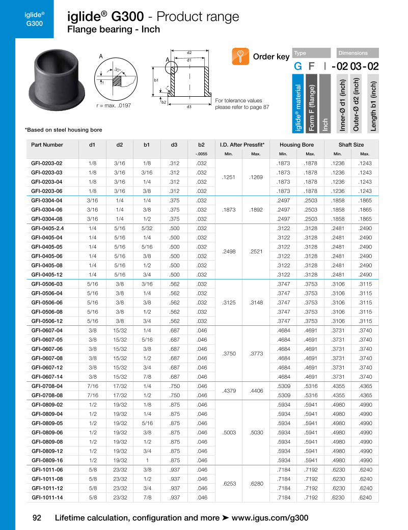
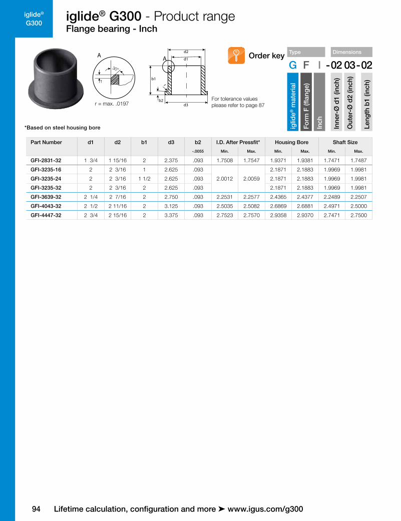
G300iglide® G300 - Product rangeFlange bearing - Inch
Type Dimensions
G F I -02 03-02
iglid
e® m
ater
ial
Form
F (fl
ange
)
Inch
Inne
r-Ø
d1
(inch
)
Out
er-Ø
d2
(inch
)
Leng
th b
1 (in
ch)
Order key
d3
d1
d2
b1r
30°
f
A A
b2 For tolerance values please refer to page 87r = max. .0197
*Based on steel housing bore
Lifetime calculation, configuration and more ➤ www.igus.com/g300
Part Number d1 d2 b1 d3 b2 I.D. After Pressfit* Housing Bore Shaft Size
-.0055 Min. Max. Min. Max. Min. Max.
GFI-0203-02 1/8 3/16 1/8 .312 .032
.1251 .1269
.1873 .1878 .1236 .1243
GFI-0203-03 1/8 3/16 3/16 .312 .032 .1873 .1878 .1236 .1243
GFI-0203-04 1/8 3/16 1/4 .312 .032 .1873 .1878 .1236 .1243
GFI-0203-06 1/8 3/16 3/8 .312 .032 .1873 .1878 .1236 .1243
GFI-0304-04 3/16 1/4 1/4 .375 .032
.1873 .1892
.2497 .2503 .1858 .1865
GFI-0304-06 3/16 1/4 3/8 .375 .032 .2497 .2503 .1858 .1865
GFI-0304-08 3/16 1/4 1/2 .375 .032 .2497 .2503 .1858 .1865
GFI-0405-2.4 1/4 5/16 5/32 .500 .032
.2498 .2521
.3122 .3128 .2481 .2490
GFI-0405-04 1/4 5/16 1/4 .500 .032 .3122 .3128 .2481 .2490
GFI-0405-05 1/4 5/16 5/16 .500 .032 .3122 .3128 .2481 .2490
GFI-0405-06 1/4 5/16 3/8 .500 .032 .3122 .3128 .2481 .2490
GFI-0405-08 1/4 5/16 1/2 .500 .032 .3122 .3128 .2481 .2490
GFI-0405-12 1/4 5/16 3/4 .500 .032 .3122 .3128 .2481 .2490
GFI-0506-03 5/16 3/8 3/16 .562 .032
.3125 .3148
.3747 .3753 .3106 .3115
GFI-0506-04 5/16 3/8 1/4 .562 .032 .3747 .3753 .3106 .3115
GFI-0506-06 5/16 3/8 3/8 .562 .032 .3747 .3753 .3106 .3115
GFI-0506-08 5/16 3/8 1/2 .562 .032 .3747 .3753 .3106 .3115
GFI-0506-12 5/16 3/8 3/4 .562 .032 .3747 .3753 .3106 .3115
GFI-0607-04 3/8 15/32 1/4 .687 .046
.3750 .3773
.4684 .4691 .3731 .3740
GFI-0607-05 3/8 15/32 5/16 .687 .046 .4684 .4691 .3731 .3740
GFI-0607-06 3/8 15/32 3/8 .687 .046 .4684 .4691 .3731 .3740
GFI-0607-08 3/8 15/32 1/2 .687 .046 .4684 .4691 .3731 .3740
GFI-0607-12 3/8 15/32 3/4 .687 .046 .4684 .4691 .3731 .3740
GFI-0607-14 3/8 15/32 7/8 .687 .046 .4684 .4691 .3731 .3740
GFI-0708-04 7/16 17/32 1/4 .750 .046.4379 .4406
.5309 .5316 .4355 .4365
GFI-0708-08 7/16 17/32 1/2 .750 .046 .5309 .5316 .4355 .4365
GFI-0809-02 1/2 19/32 1/8 .875 .046
.5003 .5030
.5934 .5941 .4980 .4990
GFI-0809-04 1/2 19/32 1/4 .875 .046 .5934 .5941 .4980 .4990
GFI-0809-05 1/2 19/32 5/16 .875 .046 .5934 .5941 .4980 .4990
GFI-0809-06 1/2 19/32 3/8 .875 .046 .5934 .5941 .4980 .4990
GFI-0809-08 1/2 19/32 1/2 .875 .046 .5934 .5941 .4980 .4990
GFI-0809-12 1/2 19/32 3/4 .875 .046 .5934 .5941 .4980 .4990
GFI-0809-16 1/2 19/32 1 .875 .046 .5934 .5941 .4980 .4990
GFI-1011-06 5/8 23/32 3/8 .937 .046
.6253 .6280
.7184 .7192 .6230 .6240
GFI-1011-08 5/8 23/32 1/2 .937 .046 .7184 .7192 .6230 .6240
GFI-1011-12 5/8 23/32 3/4 .937 .046 .7184 .7192 .6230 .6240
GFI-1011-14 5/8 23/32 7/8 .937 .046 .7184 .7192 .6230 .6240

iglide®
G300
93
iglide® G300 - Product rangeFlange bearing - Inch
Type Dimensions
G F I -02 03-02
iglid
e® m
ater
ial
Form
F (fl
ange
)
Inch
Inne
r-Ø
d1
(inch
)
Out
er-Ø
d2
(inch
)
Leng
th b
1 (in
ch)
Order key
d3
d1
d2
b1r
30°
f
A A
b2 For tolerance values please refer to page 87r = max. .0197
*Based on steel housing bore
3D-CAD files, prices and delivery time ➤ www.igus.com/g300
Part Number d1 d2 b1 d3 b2 I.D. After Pressfit* Housing Bore Shaft Size
-.0055 Min. Max. Min. Max. Min. Max.
GFI-1011-16 5/8 23/32 1 .937 .046.6253 .6280
.7184 .7192 .6230 .6240
GFI-1011-24 5/8 23/32 1 1/2 .937 .046 .7184 .7192 .6230 .6240
GFI-1214-02 3/4 7/8 1/8 1.125 .062
.7508 .7541
.8747 .8755 .7479 .7491
GFI-1214-06 3/4 7/8 3/8 1.125 .062 .8747 .8755 .7479 .7491
GFI-1214-08 3/4 7/8 1/2 1.125 .062 .8747 .8755 .7479 .7491
GFI-1214-10 3/4 7/8 5/8 1.125 .062 .8747 .8755 .7479 .7491
GFI-1214-12 3/4 7/8 3/4 1.125 .062 .8747 .8755 .7479 .7491
GFI-1214-16 3/4 7/8 1 1.125 .062 .8747 .8755 .7479 .7491
GFI-1214-24 3/4 7/8 1 1/2 1.125 .062 .8747 .8755 .7479 .7491
GFI-1416-08 7/8 1 1/2 1.250 .062
.8757 .8791
.9997 1.0005 .8729 .8741
GFI-1416-12 7/8 1 3/4 1.250 .062 .9997 1.0005 .8729 .8741
GFI-1416-16 7/8 1 1 1.250 .062 .9997 1.0005 .8729 .8741
GFI-1416-20 7/8 1 1 1/4 1.250 .062 .9997 1.0005 .8729 .8741
GFI-1416-24 7/8 1 1 1/2 1.250 .062 .9997 1.0005 .8729 .8741
GFI-1618-04 1 1 1/8 1/4 1.375 .062
1.0007 1.0041
1.1247 1.1255 .9979 .9991
GFI-1618-08 1 1 1/8 1/2 1.375 .062 1.1247 1.1255 .9979 .9991
GFI-1618-12 1 1 1/8 3/4 1.375 .062 1.1247 1.1255 .9979 .9991
GFI-1618-16 1 1 1/8 1 1.375 .062 1.1247 1.1255 .9979 .9991
GFI-1618-20 1 1 1/8 1 1/4 1.375 .062 1.1247 1.1255 .9979 .9991
GFI-1618-24 1 1 1/8 1 1/2 1.375 .062 1.1247 1.1255 .9979 .9991
GFI-1820-12 1 1/8 1 9/32 3/4 1.562 .078
1.1254 1.1288
1.2808 1.2818 1.1226 1.1238
GFI-1820-16 1 1/8 1 9/32 1 1.562 .078 1.2808 1.2818 1.1226 1.1238
GFI-1820-24 1 1/8 1 9/32 1 1/2 1.562 .078 1.2808 1.2818 1.1226 1.1238
GFI-2022-06 1 1/4 1 13/32 3/8 1.687 .078
1.2508 1.2548
1.4058 1.4068 1.2472 1.2488
GFI-2022-12 1 1/4 1 13/32 3/4 1.687 .078 1.4058 1.4068 1.2472 1.2488
GFI-2022-14 1 1/4 1 13/32 7/8 1.687 .078 1.4058 1.4068 1.2472 1.2488
GFI-2022-16 1 1/4 1 13/32 1 1.687 .078 1.4058 1.4068 1.2472 1.2488
GFI-2022-20 1 1/4 1 13/32 1 1/4 1.687 .078 1.4058 1.4068 1.2472 1.2488
GFI-2022-24 1 1/4 1 13/32 1 1/2 1.687 .078 1.4058 1.4068 1.2472 1.2488
GFI-2224-06 1 3/8 1 17/32 3/8 1.875 .0781.3758 1.3798
1.5308 1.5318 1.3722 1.3738
GFI-2224-16 1 3/8 1 17/32 1 1.875 .078 1.5308 1.5318 1.3722 1.3738
GFI-2426-08 1 1/2 1 21/32 1/2 2.000 .078
1.5008 1.5048
1.6558 1.6568 1.4972 1.4988
GFI-2426-12 1 1/2 1 21/32 3/4 2.000 .078 1.6558 1.6568 1.4972 1.4988
GFI-2426-16 1 1/2 1 21/32 1 2.000 .078 1.6558 1.6568 1.4972 1.4988
GFI-2426-24 1 1/2 1 21/32 1 1/2 2.000 .078 1.6558 1.6568 1.4972 1.4988
GFI-2831-16 1 3/4 1 15/16 1 2.375 .0931.7508 1.7547
1.9371 1.9381 1.7471 1.7487
GFI-2831-24 1 3/4 1 15/16 1 1/2 2.375 .093 1.9371 1.9381 1.7471 1.7487
94
iglide®
G300iglide® G300 - Product rangeFlange bearing - Inch
Type Dimensions
G F I -02 03-02
iglid
e® m
ater
ial
Form
F (fl
ange
)
Inch
Inne
r-Ø
d1
(inch
)
Out
er-Ø
d2
(inch
)
Leng
th b
1 (in
ch)
Order key
d3
d1
d2
b1r
30°
f
A A
b2 For tolerance values please refer to page 87r = max. .0197
*Based on steel housing bore
Lifetime calculation, configuration and more ➤ www.igus.com/g300
Part Number d1 d2 b1 d3 b2 I.D. After Pressfit* Housing Bore Shaft Size
-.0055 Min. Max. Min. Max. Min. Max.
GFI-2831-32 1 3/4 1 15/16 2 2.375 .093 1.7508 1.7547 1.9371 1.9381 1.7471 1.7487
GFI-3235-16 2 2 3/16 1 2.625 .093
2.0012 2.0059
2.1871 2.1883 1.9969 1.9981
GFI-3235-24 2 2 3/16 1 1/2 2.625 .093 2.1871 2.1883 1.9969 1.9981
GFI-3235-32 2 2 3/16 2 2.625 .093 2.1871 2.1883 1.9969 1.9981
GFI-3639-32 2 1/4 2 7/16 2 2.750 .093 2.2531 2.2577 2.4365 2.4377 2.2489 2.2507
GFI-4043-32 2 1/2 2 11/16 2 3.125 .093 2.5035 2.5082 2.6869 2.6881 2.4971 2.5000
GFI-4447-32 2 3/4 2 15/16 2 3.375 .093 2.7523 2.7570 2.9358 2.9370 2.7471 2.7500

iglide® G300 - Product RangeThrust washer - Inch
iglide®
G300
3D-CAD files, prices and delivery time ➤ www.igus.com/g300 95
d1
d2
S
d6
d4d5
h
d1
d2
S
d6
d4d5
h
Type Dimensions
G T I -04 08-005
iglid
e® m
ater
ial
Form
T (w
ashe
r)
Inch
Inne
r-Ø
d1
(inch
)
Out
er-Ø
d2
(inch
)
Thic
knes
s s
(inch
)
Order key
Part Number d1 d2 s d4 d5 h d6
+.010 -.010 -.0020 +-.005 +.015 +.005 +.008 +.005
GTI-0610-01 .375 .625 .040 * * * .375
GTI-0814-01 .500 .875 .0585 .692 .067 .040 .875
GTI-1018-01 .625 1.125 .0585 .880 .099 .040 1.125
GTI-1220-01 .750 1.250 .0585 1.005 .099 .040 1.250
GTI-1424-01 .875 1.500 .0585 1.192 .130 .040 1.500
GTI-1628-01 1.000 1.750 .0585 1.380 .130 .040 1.750
GTI-2034-01 1.250 2.125 .0585 1.692 .161 .040 2.125
GTI-2440-01 1.500 2.500 .0585 2.005 .192 .040 2.500
GTI-2844-01 1.750 2.750 .0585 2.255 .192 .040 2.750
GTI-3248-01 2.000 3.000 .0895 2.505 .192 .070 3.000
*Designed without fixation hole
96
iglide®
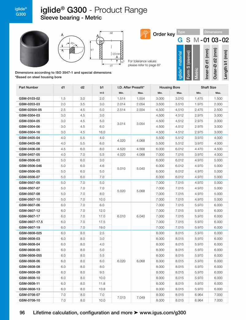
G300iglide® G300 - Product RangeSleeve bearing - Metric
0.5 mm
30°
fb1
d1
d2AA
30° For tolerance values please refer to page 87
Type Dimensions
G S M -01 03-02
iglid
e® m
ater
ial
Form
S (s
leev
e)
Met
ric
Inne
r-Ø
d1
(mm
)
Out
er-Ø
d2
(mm
)
Leng
th b
1 (m
m)
Order key
Dimensions according to ISO 3547-1 and special dimensions*Based on steel housing bore
Lifetime calculation, configuration and more ➤ www.igus.com/g300
Part Number d1 d2 b1 I.D. After Pressfit* Housing Bore Shaft Size
h13 Min. Max. Min. Max. Min. Max.
GSM-0103-02 1.5 3.0 2.0 1.514 1.554 3.000 3.010 1.475 1.500
GSM-0203-03 2.0 3.5 3.0 2.014 2.054 3.500 3.510 1.975 2.000
GSM-02504-05 2.5 4.5 5.0 2.514 2.554 4.500 4.510 2.475 2.500
GSM-0304-03 3.0 4.5 3.0
3.014 3.054
4.500 4.512 2.975 3.000
GSM-0304-05 3.0 4.5 5.0 4.500 4.512 2.975 3.000
GSM-0304-06 3.0 4.5 6.0 4.500 4.512 2.975 3.000
GSM-0304-16 3.0 4.5 16.0 4.500 4.512 2.975 3.000
GSM-0405-04 4.0 5.5 4.04.020 4.068
5.500 5.512 3.970 4.000
GSM-0405-06 4.0 5.5 6.0 5.500 5.512 3.970 4.000
GSM-0406-08 4.5 6.0 8.0 4.520 4.568 6.000 6.012 4.470 4.500
GSM-0407-05 4.0 7.0 5.5 4.020 4.068 7.000 7.015 3.970 4.000
GSM-0506-03 5.0 6.0 3.0
5.010 5.040
6.000 6.012 4.970 5.000
GSM-0506-046 5.0 6.0 4.6 6.000 6.012 4.970 5.000
GSM-0506-05 5.0 6.0 5.0 6.000 6.012 4.970 5.000
GSM-0506-07 5.0 6.0 7.0 6.000 6.012 4.970 5.000
GSM-0507-05 5.0 7.0 5.0
5.020 5.068
7.000 7.015 4.970 5.000
GSM-0507-07 5.0 7.0 7.0 7.000 7.015 4.970 5.000
GSM-0507-08 5.0 7.0 8.0 7.000 7.015 4.970 5.000
GSM-0507-10 5.0 7.0 10.0 7.000 7.015 4.970 5.000
GSM-0607-06 6.0 7.0 6.0
6.010 6.040
7.000 7.015 5.970 6.000
GSM-0607-12 6.0 7.0 12.0 7.000 7.015 5.970 6.000
GSM-0607-17 6.0 7.0 17.0 7.000 7.015 5.970 6.000
GSM-0607-17.5 6.0 7.0 17.5 7.000 7.015 5.970 6.000
GSM-0607-19 6.0 7.0 19.0 7.000 7.015 5.970 6.000
GSM-0608-025 6.0 8.0 2.5
6.020 6.068
8.000 8.015 5.970 6.000
GSM-0608-03 6.0 8.0 3.0 8.000 8.015 5.970 6.000
GSM-0608-04 6.0 8.0 4.0 8.000 8.015 5.970 6.000
GSM-0608-05 6.0 8.0 5.0 8.000 8.015 5.970 6.000
GSM-0608-055 6.0 8.0 5.5 8.000 8.015 5.970 6.000
GSM-0608-06 6.0 8.0 6.0 8.000 8.015 5.970 6.000
GSM-0608-08 6.0 8.0 8.0 8.000 8.015 5.970 6.000
GSM-0608-09 6.0 8.0 9.5 8.000 8.015 5.970 6.000
GSM-0608-10 6.0 8.0 10.0 8.000 8.015 5.970 6.000
GSM-0608-11 6.0 8.0 11.8 8.000 8.015 5.970 6.000
GSM-0608-13 6.0 8.0 13.8 8.000 8.015 5.970 6.000
GSM-0708-07 7.0 8.0 7.07.013 7.049
8.000 8.015 6.964 7.000
GSM-0708-10 7.0 8.0 10.0 8.000 8.015 6.964 7.000

iglide®
G300
97
iglide® G300 - Product RangeSleeve bearing - Metric
Type Dimensions
G S M -01 03-02
iglid
e® m
ater
ial
Form
S (s
leev
e)
Met
ric
Inne
r-Ø
d1
(mm
)
Out
er-Ø
d2
(mm
)
Leng
th b
1 (m
m)
Order key
0.5 mm
30°
fb1
d1
d2AA
30° For tolerance values please refer to page 87
Dimensions according to ISO 3547-1 and special dimensions*Based on steel housing bore
3D-CAD files, prices and delivery time ➤ www.igus.com/g300
Part Number d1 d2 b1 I.D. After Pressfit* Housing Bore Shaft Size
h13 Min. Max. Min. Max. Min. Max.
GSM-0708-19 7.0 8.0 19.0 7.013 7.049 8.000 8.015 6.964 7.000
GSM-0709-05 7.0 9.0 5.0
7.025 7.083
9.000 9.015 6.964 7.000
GSM-0709-08 7.0 9.0 8.0 9.000 9.015 6.964 7.000
GSM-0709-09 7.0 9.0 9.0 9.000 9.015 6.964 7.000
GSM-0709-10 7.0 9.0 10.0 9.000 9.015 6.694 7.000
GSM-0709-12 7.0 9.0 12.0 9.000 9.015 6.694 7.000
GSM-0809-03 8.0 9.0 3.0
8.013 8.049
9.000 9.015 7.964 8.000
GSM-0809-05 8.0 9.0 5.0 9.000 9.015 7.964 8.000
GSM-0809-06 8.0 9.0 6.0 9.000 9.015 7.964 8.000
GSM-0809-08 8.0 9.0 8.0 9.000 9.015 7.964 8.000
GSM-0809-12 8.0 9.0 12.0 9.000 9.015 7.964 8.000
GSM-0810-05 8.0 10.0 5.0
8.025 8.083
10.000 10.015 7.964 8.000
GSM-0810-06 8.0 10.0 6.0 10.000 10.015 7.964 8.000
GSM-0810-07 8.0 10.0 7.0 10.000 10.015 7.964 8.000
GSM-0810-08 8.0 10.0 8.0 10.000 10.015 7.964 8.000
GSM-0810-10 8.0 10.0 10.0 10.000 10.015 7.964 8.000
GSM-0810-12 8.0 10.0 12.0 10.000 10.015 7.964 8.000
GSM-0810-13 8.0 10.0 13.0 10.000 10.015 7.964 8.000
GSM-0810-14 8.0 10.0 14.0 10.000 10.015 7.964 8.000
GSM-0810-15 8.0 10.0 15.0 10.000 10.015 7.964 8.000
GSM-0810-16 8.0 10.0 16.0 10.000 10.015 7.964 8.000
GSM-0810-18 8.0 10.0 18.0 10.000 10.015 7.964 8.000
GSM-0810-20 8.0 10.0 20.0 10.000 10.015 7.964 8.000
GSM-0810-22 8.0 10.0 22.0 10.000 10.015 7.964 8.000
GSM-0810-25 8.0 10.0 25.0 10.000 10.015 7.964 8.000
GSM-0910-12 9.0 10.0 12.09.013 9.049
10.000 10.015 8.964 9.000
GSM-0910-16 9.0 10.0 16.0 10.000 10.015 8.964 9.000
GSM-0911-06 9.0 11.0 6.09.025 9.083
11.000 11.018 8.964 9.000
GSM-0911-20 9.0 11.0 20.0 11.000 11.018 8.964 9.000
GSM-1011-06 10.0 11.0 6.0
10.013 10.049
11.000 11.018 9.964 10.000
GSM-1011-07 10.0 11.0 7.0 11.000 11.018 9.964 10.000
GSM-1011-10 10.0 11.0 10.0 11.000 11.018 9.964 10.000
GSM-1011-20 10.0 11.0 20.0 11.000 11.018 9.964 10.000
GSM-1011-25 10.0 11.0 25.0 11.000 11.018 9.964 10.000
GSM-1011-30 10.0 11.0 30.0 11.000 11.018 9.964 10.000
GSM-1012-04 10.0 12.0 4.010.025 10.083
12.000 12.018 9.964 10.000
GSM-1012-045 10.0 12.0 4.5 12.000 12.018 9.964 10.000

98
iglide®
G300iglide® G300 - Product RangeSleeve bearing - Metric
0.5 mm
30°
fb1
d1
d2AA
30° For tolerance values please refer to page 87
Type Dimensions
G S M -01 03-02
iglid
e® m
ater
ial
Form
S (s
leev
e)
Met
ric
Inne
r-Ø
d1
(mm
)
Out
er-Ø
d2
(mm
)
Leng
th b
1 (m
m)
Order key
Dimensions according to ISO 3547-1 and special dimensions*Based on steel housing bore
Lifetime calculation, configuration and more ➤ www.igus.com/g300
Part Number d1 d2 b1 I.D. After Pressfit* Housing Bore Shaft Size
h13 Min. Max. Min. Max. Min. Max.
GSM-1012-05 10.0 12.0 5.0
10.025 10.083
12.000 12.018 9.964 10.000
GSM-1012-06 10.0 12.0 6.0 12.000 12.018 9.964 10.000
GSM-1012-07 10.0 12.0 7.0 12.000 12.018 9.964 10.000
GSM-1012-08 10.0 12.0 8.0 12.000 12.018 9.964 10.000
GSM-1012-09 10.0 12.0 9.0 12.000 12.018 9.964 10.000
GSM-1012-10 10.0 12.0 10.0 12.000 12.018 9.964 10.000
GSM-1012-12 10.0 12.0 12.0 12.000 12.018 9.964 10.000
GSM-1012-14 10.0 12.0 14.0 12.000 12.018 9.964 10.000
GSM-1012-15 10.0 12.0 15.0 12.000 12.018 9.964 10.000
GSM-1012-17 10.0 12.0 17.0 12.000 12.018 9.964 10.000
GSM-1012-20 10.0 12.0 20.0 12.000 12.018 9.964 10.000
GSM-1013-13 10.0 13.0 13.5 10.025 10.083 13.000 13.018 9.964 10.000
GSM-1014-10 10.0 14.0 10.010.025 10.083
14.000 14.018 9.964 10.000
GSM-1014-20 10.0 14.0 20.0 14.000 14.018 9.964 10.000
GSM-1016-10 10.0 16.0 10.010.040 10.130
16.000 16.018 9.964 10.000
GSM-1016-50 10.0 16.0 50.0 16.000 16.018 9.964 10.000
GSM-1213-047 12.0 13.0 4.7
12.016 12.059
13.000 13.018 11.957 12.000
GSM-1213-10 12.0 13.0 10.0 13.000 13.018 11.957 12.000
GSM-1213-12 12.0 13.0 12.0 13.000 13.018 11.957 12.000
GSM-1213-15 12.0 13.0 15.0 13.000 13.018 11.957 12.000
GSM-1214-04 12.0 14.0 4.0
12.032 12.102
14.000 14.018 11.957 12.000
GSM-1214-05 12.0 14.0 5.0 14.000 14.018 11.957 12.000
GSM-1214-06 12.0 14.0 6.0 14.000 14.018 11.957 12.000
GSM-1214-08 12.0 14.0 8.0 14.000 14.018 11.957 12.000
GSM-1214-10 12.0 14.0 10.0 14.000 14.018 11.957 12.000
GSM-1214-12 12.0 14.0 12.0 14.000 14.018 11.957 12.000
GSM-1214-14 12.0 14.0 14.0 14.000 14.018 11.957 12.000
GSM-1214-15 12.0 14.0 15.0 14.000 14.018 11.957 12.000
GSM-1214-20 12.0 14.0 20.0 14.000 14.018 11.957 12.000
GSM-1214-25 12.0 14.0 25.0 14.000 14.018 11.957 12.000
GSM-1215-06 12.0 15.0 6.012.032 12.102
15.000 15.018 11.957 12.000
GSM-1215-22 12.0 15.0 22.0 15.000 15.018 11.957 12.000
GSM-1216-10 12.0 16.0 10.012.032 12.102
16.000 16.018 11.957 12.000
GSM-1216-20 12.0 16.0 20.0 16.000 16.018 11.957 12.000
GSM-1315-07 13.0 15.0 7.0
13.032 13.102
15.000 15.018 12.957 13.000
GSM-1315-075 13.0 15.0 7.5 15.000 15.018 12.957 13.000
GSM-1315-10 13.0 15.0 10.0 15.000 15.018 12.957 13.000

iglide®
G300
99
iglide® G300 - Product RangeSleeve bearing - Metric
Type Dimensions
G S M -01 03-02
iglid
e® m
ater
ial
Form
S (s
leev
e)
Met
ric
Inne
r-Ø
d1
(mm
)
Out
er-Ø
d2
(mm
)
Leng
th b
1 (m
m)
Order key
0.5 mm
30°
fb1
d1
d2AA
30° For tolerance values please refer to page 87
Dimensions according to ISO 3547-1 and special dimensions*Based on steel housing bore
3D-CAD files, prices and delivery time ➤ www.igus.com/g300
Part Number d1 d2 b1 I.D. After Pressfit* Housing Bore Shaft Size
h13 Min. Max. Min. Max. Min. Max.
GSM-1315-15 13.0 15.0 15.0
13.032 13.102
15.000 15.018 12.957 13.000
GSM-1315-20 13.0 15.0 20.0 15.000 15.018 12.957 13.000
GSM-1315-25 13.0 15.0 25.0 15.000 15.018 12.957 13.000
GSM-1416-03 14.0 16.0 3.0
14.032 14.102
16.000 16.018 13.957 14.000
GSM-1416-06 14.0 16.0 6.0 16.000 16.018 13.957 14.000
GSM-1416-08 14.0 16.0 8.0 16.000 16.018 13.957 14.000
GSM-1416-10 14.0 16.0 10.0 16.000 16.018 13.957 14.000
GSM-1416-12 14.0 16.0 12.0 16.000 16.018 13.957 14.000
GSM-1416-15 14.0 16.0 15.0 16.000 16.018 13.957 14.000
GSM-1416-20 14.0 16.0 20.0 16.000 16.018 13.957 14.000
GSM-1416-25 14.0 16.0 25.0 16.000 16.018 13.957 14.000
GSM-1416-45 14.0 16.0 45.0 16.000 16.018 13.957 14.000
GSM-1516-10 15.0 16.0 10.015.016 15.059
16.000 16.018 14.957 15.000
GSM-1516-15 15.0 16.0 15.0 16.000 16.018 14.957 15.000
GSM-1517-04 15.0 17.0 4.0
15.032 15.102
17.000 17.018 14.957 15.000
GSM-1517-10 15.0 17.0 10.0 17.000 17.018 14.957 15.000
GSM-1517-12 15.0 17.0 12.0 17.000 17.018 14.957 15.000
GSM-1517-15 15.0 17.0 15.0 17.000 17.018 14.957 15.000
GSM-1517-20 15.0 17.0 20.0 17.000 17.018 14.957 15.000
GSM-1517-25 15.0 17.0 25.0 17.000 17.018 14.957 15.000
GSM-1618-055 16.0 18.0 5.5
16.032 16.102
18.000 18.018 15.957 16.000
GSM-1618-08 16.0 18.0 8.0 18.000 18.018 15.957 16.000
GSM-1618-10 16.0 18.0 10.0 18.000 18.018 15.957 16.000
GSM-1618-12 16.0 18.0 12.0 18.000 18.018 15.957 16.000
GSM-1618-13.5 16.0 18.0 13.5 18.000 18.018 15.957 16.000
GSM-1618-13.8 16.0 18.0 13.8 18.000 18.018 15.957 16.000
GSM-1618-15 16.0 18.0 15.0 18.000 18.018 15.957 16.000
GSM-1618-20 16.0 18.0 20.0 18.000 18.018 15.957 16.000
GSM-1618-25 16.0 18.0 25.0 18.000 18.018 15.957 16.000
GSM-1618-30 16.0 18.0 30.0 18.000 18.018 15.957 16.000
GSM-1618-50 16.0 18.0 50.0 18.000 18.018 15.957 16.000
GSM-1719-15 17.0 19.0 15.0 17.032 17.102 19.000 19.021 16.957 17.000
GSM-1819-15 18.0 19.0 15.0 18.032 18.102 19.000 19.021 17.957 18.000
GSM-1820-06 18.0 20.0 6.0
18.032 18.102
20.000 20.021 17.957 18.000
GSM-1820-10 18.0 20.0 10.0 20.000 20.021 17.957 18.000
GSM-1820-12 18.0 20.0 12.0 20.000 20.021 17.957 18.000
GSM-1820-15 18.0 20.0 15.0 20.000 20.021 17.957 18.000
100
iglide®
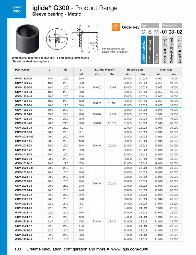
G300iglide® G300 - Product RangeSleeve bearing - Metric
0.5 mm
30°
fb1
d1
d2AA
30° For tolerance values please refer to page 87
Type Dimensions
G S M -01 03-02
iglid
e® m
ater
ial
Form
S (s
leev
e)
Met
ric
Inne
r-Ø
d1
(mm
)
Out
er-Ø
d2
(mm
)
Leng
th b
1 (m
m)
Order key
Dimensions according to ISO 3547-1 and special dimensions*Based on steel housing bore
Lifetime calculation, configuration and more ➤ www.igus.com/g300
Part Number d1 d2 b1 I.D. After Pressfit* Housing Bore Shaft Size
h13 Min. Max. Min. Max. Min. Max.
GSM-1820-20 18.0 20.0 20.0
18.032 18.102
20.000 20.021 17.957 18.000
GSM-1820-25 18.0 20.0 25.0 20.000 20.021 17.957 18.000
GSM-1820-34 18.0 20.0 34.0 20.000 20.021 17.957 18.000
GSM-1820-38 18.0 20.0 38.0 20.000 20.021 17.957 18.000
GSM-1820-45 18.0 20.0 45.0 20.000 20.021 17.957 18.000
GSM-1822-15 18.0 22.0 15.018.032 18.102
22.000 22.021 17.957 18.000
GSM-1822-30 18.0 22.0 30.0 22.000 22.021 17.957 18.000
GSM-1922-06 19.0 22.0 6.0
19.040 19.124
22.000 22.021 18.948 19.000
GSM-1922-28 19.0 22.0 28.0 22.000 22.021 18.948 19.000
GSM-1922-35 19.0 22.0 35.0 22.000 22.021 18.948 19.000
GSM-2021-20 20.0 21.0 20.0 20.020 20.072 21.000 21.021 19.948 20.000
GSM-2022-03 20.0 22.0 3.0
20.040 20.124
22.000 22.021 19.948 20.000
GSM-2022-08 20.0 22.0 8.0 22.000 22.021 19.948 20.000
GSM-2022-105 20.0 22.0 10.5 22.000 22.021 19.948 20.000
GSM-2022-15 20.0 22.0 15.0 22.000 22.021 19.948 20.000
GSM-2022-20 20.0 22.0 20.0 22.000 22.021 19.948 20.000
GSM-2022-22 20.0 22.0 22.0 22.000 22.021 19.948 20.000
GSM-2022-28 20.0 22.0 28.0 22.000 22.021 19.948 20.000
GSM-2022-30 20.0 22.0 30.0 22.000 22.021 19.948 20.000
GSM-2022-47 20.0 22.0 47.0 22.000 22.021 19.948 20.000
GSM-2023-045 20.0 23.0 4.5
20.040 20.124
23.000 23.021 19.948 20.000
GSM-2023-10 20.0 23.0 10.0 23.000 23.021 19.948 20.000
GSM-2023-15 20.0 23.0 15.0 23.000 23.021 19.948 20.000
GSM-2023-20 20.0 23.0 20.0 23.000 23.021 19.948 20.000
GSM-2023-23 20.0 23.0 23.0 23.000 23.021 19.948 20.000
GSM-2023-24 20.0 23.0 24.0 23.000 23.021 19.948 20.000
GSM-2023-25 20.0 23.0 25.0 23.000 23.021 19.948 20.000
GSM-2023-30 20.0 23.0 30.0 23.000 23.021 19.948 20.000
GSM-2224-05 22.0 24.0 5.0
22.040 22.124
24.000 24.021 21.948 22.000
GSM-2224-08 22.0 24.0 8.0 24.000 24.021 21.948 22.000
GSM-2224-10 22.0 24.0 10.0 24.000 24.021 21.948 22.000
GSM-2224-12 22.0 24.0 12.0 24.000 24.021 21.948 22.000
GSM-2224-15 22.0 24.0 15.0 24.000 24.021 21.948 22.000
GSM-2224-17 22.0 24.0 17.0 24.000 24.021 21.948 22.000
GSM-2224-20 22.0 24.0 20.0 24.000 24.021 21.948 22.000
GSM-2224-30 22.0 24.0 30.0 24.000 24.021 21.948 22.000
GSM-2224-48 22.0 24.0 48.0 24.000 24.021 21.948 22.000

iglide®
G300
101
iglide® G300 - Product RangeSleeve bearing - Metric
Type Dimensions
G S M -01 03-02
iglid
e® m
ater
ial
Form
S (s
leev
e)
Met
ric
Inne
r-Ø
d1
(mm
)
Out
er-Ø
d2
(mm
)
Leng
th b
1 (m
m)
Order key
0.5 mm
30°
fb1
d1
d2AA
30° For tolerance values please refer to page 87
Dimensions according to ISO 3547-1 and special dimensions*Based on steel housing bore
3D-CAD files, prices and delivery time ➤ www.igus.com/g300
Part Number d1 d2 b1 I.D. After Pressfit* Housing Bore Shaft Size
h13 Min. Max. Min. Max. Min. Max.
GSM-2225-15 22.0 25.0 15.0
22.040 22.124
25.000 25.021 21.948 22.000
GSM-2225-20 22.0 25.0 20.0 25.000 25.021 21.948 22.000
GSM-2225-25 22.0 25.0 25.0 25.000 25.021 21.948 22.000
GSM-2225-30 22.0 25.0 30.0 25.000 25.021 21.948 22.000
GSM-2427-06 24.0 27.0 6.0
24.040 24.124
27.000 27.021 23.948 24.000
GSM-2427-15 24.0 27.0 15.0 27.000 27.021 23.948 24.000
GSM-2427-20 24.0 27.0 20.0 27.000 27.021 23.948 24.000
GSM-2427-24 24.0 27.0 24.0 27.000 27.021 23.948 24.000
GSM-2427-25 24.0 27.0 25.0 27.000 27.021 23.948 24.000
GSM-2427-30 24.0 27.0 30.0 27.000 27.021 23.948 24.000
GSM-2526-23 25.0 26.0 23.025.020 25.072
26.000 26.021 24.948 25.000
GSM-2526-25 25.0 26.0 25.0 26.000 26.021 24.948 25.000
GSM-2528-12 25.0 28.0 12.0
25.040 25.124
28.000 28.021 24.948 25.000
GSM-2528-15 25.0 28.0 15.0 28.000 28.021 24.948 25.000
GSM-2528-20 25.0 28.0 20.0 28.000 28.021 24.948 25.000
GSM-2528-24 25.0 28.0 24.0 28.000 28.021 24.948 25.000
GSM-2528-25 25.0 28.0 25.0 28.000 28.021 24.948 25.000
GSM-2528-30 25.0 28.0 30.0 28.000 28.021 24.948 25.000
GSM-2528-35 25.0 28.0 35.0 28.000 28.021 24.948 25.000
GSM-2528-50 25.0 28.0 50.0 28.000 28.021 24.948 25.000
GSM-2630-16 26.0 30.0 16.0 26.040 26.124 30.000 30.021 25.948 26.000
GSM-2730-05 27.0 30.0 5.0 26.040 27.124 30.000 30.021 26.948 27.000
GSM-2832-10.5 28.0 32.0 10.5
28.040 28.124
32.000 32.025 27.948 28.000
GSM-2832-12 28.0 32.0 12.0 32.000 32.025 27.948 28.000
GSM-2832-15 28.0 32.0 15.0 32.000 32.025 27.948 28.000
GSM-2832-20 28.0 32.0 20.0 32.000 32.025 27.948 28.000
GSM-2832-23 28.0 32.0 23.0 32.000 32.025 27.948 28.000
GSM-2832-25 28.0 32.0 25.0 32.000 32.025 27.948 28.000
GSM-2832-30 28.0 32.0 30.0 32.000 32.025 27.948 28.000
GSM-3031-12 30.0 31.0 12.030.020 30.072
31.000 31.025 29.948 30.000
GSM-3031-30 30.0 31.0 30.0 31.000 31.025 29.948 30.000
GSM-3034-12 30.0 34.0 12.0
30.040 30.124
34.000 34.025 29.948 30.000
GSM-3034-15 30.0 34.0 15.0 34.000 34.025 29.948 30.000
GSM-3034-20 30.0 34.0 20.0 34.000 34.025 29.948 30.000
GSM-3034-24 30.0 34.0 24.0 34.000 34.025 29.948 30.000
GSM-3034-25 30.0 34.0 25.0 34.000 34.025 29.948 30.000
GSM-3034-30 30.0 34.0 30.0 34.000 34.025 29.948 30.000

102
iglide®
G300iglide® G300 - Product RangeSleeve bearing - Metric
0.5 mm
30°
fb1
d1
d2AA
30° For tolerance values please refer to page 87
Type Dimensions
G S M -01 03-02
iglid
e® m
ater
ial
Form
S (s
leev
e)
Met
ric
Inne
r-Ø
d1
(mm
)
Out
er-Ø
d2
(mm
)
Leng
th b
1 (m
m)
Order key
Dimensions according to ISO 3547-1 and special dimensions*Based on steel housing bore
Lifetime calculation, configuration and more ➤ www.igus.com/g300
Part Number d1 d2 b1 I.D. After Pressfit* Housing Bore Shaft Size
h13 Min. Max. Min. Max. Min. Max.
GSM-3034-35 30.0 34.0 35.030.040 30.124
34.000 34.025 29.948 30.000
GSM-3034-40 30.0 34.0 40.0 34.000 34.025 29.948 30.000
GSM-3236-15 32.0 36.0 15.0
32.050 32.150
36.000 36.025 31.938 32.000
GSM-3236-20 32.0 36.0 20.0 36.000 36.025 31.938 32.000
GSM-3236-30 32.0 36.0 30.0 36.000 36.025 31.938 32.000
GSM-3236-40 32.0 36.0 40.0 36.000 36.025 31.938 32.000
GSM-3539-14 35.0 39.0 14.0
35.050 35.150
39.000 39.025 34.938 35.000
GSM-3539-20 35.0 39.0 20.0 39.000 39.025 34.938 35.000
GSM-3539-25 35.0 39.0 25.0 39.000 39.025 34.938 35.000
GSM-3539-30 35.0 39.0 30.0 39.000 39.025 34.938 35.000
GSM-3539-40 35.0 39.0 40.0 39.000 39.025 34.938 35.000
GSM-3539-50 35.0 39.0 50.0 39.000 39.025 34.938 35.000
GSM-3640-20 36.0 40.0 20.0 36.050 36.150 40.000 40.025 35.938 36.000
GSM-3741-20 37.0 41.0 20.0 37.050 37.150 41.000 41.025 36.938 37.000
GSM-4044-10 40.0 44.0 10.0
40.050 40.150
44.000 44.025 39.938 40.000
GSM-4044-16 40.0 44.0 16.0 44.000 44.025 39.938 40.000
GSM-4044-20 40.0 44.0 20.0 44.000 44.025 39.938 40.000
GSM-4044-30 40.0 44.0 30.0 44.000 44.025 39.938 40.000
GSM-4044-40 40.0 44.0 40.0 44.000 44.025 39.938 40.000
GSM-4044-50 40.0 44.0 50.0 44.000 44.025 39.938 40.000
GSM-4246-40 42.0 46.0 40.0 42.050 42.150 46.000 46.025 41.938 42.000
GSM-4550-10 45.0 50.0 10.0
45.050 45.150
50.000 50.025 44.938 45.000
GSM-4550-20 45.0 50.0 20.0 50.000 50.025 44.938 45.000
GSM-4550-22 45.0 50.0 22.0 50.000 50.025 44.938 45.000
GSM-4550-30 45.0 50.0 30.0 50.000 50.025 44.938 45.000
GSM-4550-38 45.0 50.0 38.0 50.000 50.025 44.938 45.000
GSM-4550-40 45.0 50.0 40.0 50.000 50.025 44.938 45.000
GSM-4550-50 45.0 50.0 50.0 50.000 50.025 44.938 45.000
GSM-5053-25 50.0 53.0 25.050.050 50.150
53.000 53.030 49.938 50.000
GSM-5053-50 50.0 53.0 50.0 53.000 53.030 49.938 50.000
GSM-5055-20 50.0 55.0 20.0
50.050 50.150
55.000 55.030 49.938 50.000
GSM-5055-25 50.0 55.0 25.0 55.000 55.030 49.938 50.000
GSM-5055-30 50.0 55.0 30.0 55.000 55.030 49.938 50.000
GSM-5055-40 50.0 55.0 40.0 55.000 55.030 49.938 50.000
GSM-5055-50 50.0 55.0 50.0 55.000 55.030 49.938 50.000
GSM-5055-60 50.0 55.0 60.0 55.000 55.030 49.938 50.000
GSM-5257-20 52.0 57.0 20.0 52.060 52.180 57.000 57.030 51.926 52.000

iglide®
G300
103
iglide® G300 - Product RangeSleeve bearing - Metric
Type Dimensions
G S M -01 03-02
iglid
e® m
ater
ial
Form
S (s
leev
e)
Met
ric
Inne
r-Ø
d1
(mm
)
Out
er-Ø
d2
(mm
)
Leng
th b
1 (m
m)
Order key
0.5 mm
30°
fb1
d1
d2AA
30° For tolerance values please refer to page 87
Dimensions according to ISO 3547-1 and special dimensions*Based on steel housing bore
3D-CAD files, prices and delivery time ➤ www.igus.com/g300
Part Number d1 d2 b1 I.D. After Pressfit* Housing Bore Shaft Size
h13 Min. Max. Min. Max. Min. Max.
GSM-5560-20 55.0 60.0 20.0
55.060 55.180
60.000 60.030 54.926 55.000
GSM-5560-40 55.0 60.0 40.0 60.000 60.030 54.926 55.000
GSM-5560-50 55.0 60.0 50.0 60.000 60.030 54.926 55.000
GSM-5560-60 55.0 60.0 60.0 60.000 60.030 54.926 55.000
GSM-6065-30 60.0 65.0 30.0
60.060 60.180
65.000 65.030 59.926 60.000
GSM-6065-40 60.0 65.0 40.0 65.000 65.030 59.926 60.000
GSM-6065-50 60.0 65.0 50.0 65.000 65.030 59.926 60.000
GSM-6065-60 60.0 65.0 60.0 65.000 65.030 59.926 60.000
GSM-6065-70 60.0 65.0 70.0 65.000 65.030 59.926 60.000
GSM-6267-35 62.0 67.0 35.0
62.060 62.180
67.000 67.030 61.926 62.000
GSM-6267-70 62.0 67.0 70.0 67.000 67.030 61.926 62.000
GSM-6267-72 62.0 67.0 72.0 67.000 67.030 61.926 62.000
GSM-6570-30 65.0 70.0 30.065.060 65.180
70.000 70.030 64.926 65.000
GSM-6570-50 65.0 70.0 50.0 70.000 70.030 64.926 65.000
GSM-7075-60 70.0 75.0 60.0 70.060 70.180 75.000 75.030 69.926 70.000
GSM-7277-76 72.0 77.0 76.072.060 72.180
77.000 77.030 71.926 72.000
GSM-7277-78 72.0 77.0 78.0 77.000 77.030 71.926 72.000
GSM-7580-40 75.0 80.0 40.075.060 75.180
80.000 80.030 74.926 75.000
GSM-7580-60 75.0 80.0 60.0 80.000 80.030 74.926 75.000
GSM-8085-60 80.0 85.0 60.080.060 80.180
85.000 85.035 79.926 80.000
GSM-8085-100 80.0 85.0 100.0 85.000 85.035 79.926 80.000
GSM-8590-100 85.0 90.0 100.0 85.072 85.212 90.000 90.035 84.913 85.000
GSM-9095-100 90.0 95.0 100.0 90.072 90.212 95.000 95.035 89.913 90.000
GSM-95100-100 95.0 100.0 100.0 95.072 95.212 100.000 100.035 94.913 95.000
GSM-100105-30 100.0 105.0 30.0
100.072 100.212
105.000 105.035 99.913 100.000
GSM-100105-40 100.0 105.0 40.0 105.000 105.035 99.913 100.000
GSM-100105-100 100.0 105.0 100.0 105.000 105.035 99.913 100.000
GSM-110115-100 110.0 115.0 100.0 110.072 110.212 115.000 115.035 109.913 110.000
GSM-120125-100 120.0 125.0 100.0 120.072 120.212 125.000 125.040 119.913 120.000
GSM-125130-100 125.0 130.0 100.0 125.085 125.245 130.000 130.040 124.900 125.000
GSM-130135-100 130.0 135.0 100.0 130.085 130.245 135.000 135.040 129.900 130.000
GSM-135140-80 135.0 140.0 80.0 135.085 135.245 140.000 140.040 134.900 135.000
GSM-140145-100 140.0 145.0 100.0 140.085 140.245 145.000 145.040 139.900 140.000
GSM-150155-100 150.0 155.0 100.0 150.085 150.245 155.000 155.040 149.900 150.000

104
iglide®
G300
r = max. 0.5
iglide® G300 - Product RangeFlange bearing - Metric
d3
d1
d2
b1r
30°
f
A A
b2 For tolerance values please refer to page 87
Type Dimensions
G F M -01 03-02
iglid
e® m
ater
ial
Form
F (fl
ange
)
Met
ric
Inne
r-Ø
d1
(mm
)
Out
er-Ø
d2
(mm
)
Leng
th b
1 (m
m)
Order key
Dimensions according to ISO 3547-1 and special dimensions*Based on steel housing bore
Part Number d11) d2 d3 b1 b2 I.D. After Pressfit* Housing Bore Shaft Size
d13 h13 -0.14 Min. Max. Min. Max. Min. Max.
GFM-0304-02 3.0 4.5 7.5 2.0 0.75
3.014 3.054
4.500 4.512 2.975 3.000
GFM-0304-0275 3.0 4.5 7.0 2.75 0.75 4.500 4.512 2.975 3.000
GFM-0304-03 3.0 4.5 7.5 3.0 0.75 4.500 4.512 2.975 3.000
GFM-0304-05 3.0 4.5 7.5 5.0 0.75 4.500 4.512 2.975 3.000
GFM-030407-05 3.0 4.5 7.0 5.0 0.75 4.500 4.512 2.975 3.000
GFM-0405-03 4.0 5.5 9.5 3.0 0.75
4.020 4.068
5.500 5.512 3.970 4.000
GFM-0405-04 4.0 5.5 9.5 4.0 0.75 5.500 5.512 3.970 4.000
GFM-0405-06 4.0 5.5 9.5 6.0 0.75 5.500 5.512 3.970 4.000
GFM-040508-10 4.0 5.5 8.0 10.0 0.75 5.500 5.512 3.970 4.000
GFM-0506-035 5.0 6.0 10.0 3.5 0.5
5.010 5.040
6.000 6.012 4.970 5.000
GFM-0506-04 5.0 6.0 10.0 4.0 0.5 6.000 6.012 4.970 5.000
GFM-0506-05 5.0 6.0 10.0 5.0 0.5 6.000 6.012 4.970 5.000
GFM-0506-06 5.0 6.0 10.0 6.0 0.5 6.000 6.012 4.970 5.000
GFM-0506-15 5.0 6.0 10.0 15.25 0.5 6.000 6.012 4.970 5.000
GFM-0507-03 5.0 7.0 11.0 3.5 1.0
5.020 5.068
7.000 7.015 4.970 5.000
GFM-0507-04 5.0 7.0 11.0 4.0 1.0 7.000 7.015 4.970 5.000
GFM-0507-05 5.0 7.0 11.0 5.0 1.0 7.000 7.015 4.970 5.000
GFM-0507-07 5.0 7.0 11.0 7.0 1.0 7.000 7.015 4.970 5.000
GFM-0507-11 5.0 7.0 11.0 11.0 1.0 7.000 7.015 4.970 5.000
GFM-0507-30 5.0 7.0 11.0 30.0 1.0 7.000 7.015 4.970 5.000
GFM-050715-04 5.0 7.0 15.0 4.0 1.0 7.000 7.015 4.970 5.000
GFM-050709-05 5.0 7.0 9.0 5.0 1.0 7.000 7.015 4.970 5.000
GFM-0607-06 6.0 7.0 11.0 6.0 0.5
6.010 6.040
7.000 7.015 5.970 6.000
GFM-0607-10 6.0 7.0 11.0 10.0 0.5 7.000 7.015 5.970 6.000
GFM-0607-024 6.0 7.0 11.0 2.4 0.5 7.000 7.015 5.970 6.000
GFM-0608-04 6.0 8.0 12.0 4.0 1.0
6.020 6.068
8.000 8.015 5.970 6.000
GFM-0608-048 6.0 8.0 12.0 4.8 1.0 8.000 8.015 5.970 6.000
GFM-0608-05 6.0 8.0 12.0 5.0 1.0 8.000 8.015 5.970 6.000
GFM-0608-06 6.0 8.0 12.0 6.0 1.0 8.000 8.015 5.970 6.000
GFM-0608-07 6.0 8.0 12.0 7.0 1.0 8.000 8.015 5.970 6.000
GFM-0608-08 6.0 8.0 12.0 8.0 1.0 8.000 8.015 5.970 6.000
GFM-0608-10 6.0 8.0 12.0 10.0 1.0 8.000 8.015 5.970 6.000
GFM-060810-08 6.0 8.0 10.0 8.0 1.0 8.000 8.015 5.970 6.000
GFM-060812-20 6.0 8.0 12.0 20.0 1.0 8.000 8.015 5.970 6.000
GFM-060814-12 6.0 8.0 14.0 12.0 1.0 8.000 8.015 5.970 6.000
GFM-0608-25 6.0 8.0 12.0 25.0 1.0 8.000 8.015 5.970 6.000
GFM-0608-35 6.0 8.0 12.0 35.0 1.0 8.000 8.015 5.970 6.000

iglide® G300 - Product RangeFlange bearing - Metric
iglide®
G300
105
r = max. 0.5
Type Dimensions
G F M -01 03-02
iglid
e® m
ater
ial
Form
F (fl
ange
)
Met
ric
Inne
r-Ø
d1
(mm
)
Out
er-Ø
d2
(mm
)
Leng
th b
1 (m
m)
Order key
d3
d1
d2
b1r
30°
f
A A
b2 For tolerance values please refer to page 87
Dimensions according to ISO 3547-1 and special dimensions*Based on steel housing bore
Part Number d11) d2 d3 b1 b2 I.D. After Pressfit* Housing Bore Shaft Size
d13 h13 -0.14 Min. Max. Min. Max. Min. Max.
GFM-0708-03 7.0 8.0 12.0 3.0 0.5
7.013 7.049
8.000 8.015 6.964 7.000
GFM-0708-06 7.0 8.0 12.0 6.0 0.5 8.000 8.015 6.964 7.000
GFM-0708-08 7.0 8.0 12.0 8.0 0.5 8.000 8.015 6.964 7.000
GFM-0709-03.5 7.0 9.0 15.0 3.5 1.0
7.025 7.083
9.000 9.015 6.964 7.000
GFM-0709-06 7.0 9.0 15.0 6.0 1.0 9.000 9.015 6.964 7.000
GFM-0709-10 7.0 9.0 15.0 10.0 1.0 9.000 9.015 6.964 7.000
GFM-0709-12 7.0 9.0 15.0 12.0 1.0 9.000 9.015 6.964 7.000
GFM-070919-10 7.0 9.0 19.0 10.0 1.0 9.000 9.015 6.964 7.000
GFM-0809-03 8.0 9.0 15.0 3.0 0.5
8.013 8.049
9.000 9.015 7.964 8.000
GFM-0809-035 8.0 9.0 13.0 3.5 0.5 9.000 9.015 7.964 8.000
GFM-0809-055 8.0 9.0 13.0 5.5 0.5 9.000 9.015 7.964 8.000
GFM-0809-08 8.0 9.0 13.0 8.0 0.5 9.000 9.015 7.964 8.000
GFM-0809-12 8.0 9.0 13.0 12.0 0.5 9.000 9.015 7.964 8.000
GFM-0810-02 8.0 10.0 15.0 2.7 1.0
8.025 8.083
10.000 10.015 7.964 8.000
GFM-0810-03 8.0 10.0 15.0 3.0 1.0 10.000 10.015 7.964 8.000
GFM-0810-035 8.0 10.0 15.0 3.5 1.0 10.000 10.015 7.964 8.000
GFM-0810-04 8.0 10.0 15.0 4.0 1.0 10.000 10.015 7.964 8.000
GFM-0810-05 8.0 10.0 15.0 5.5 1.0 10.000 10.015 7.964 8.000
GFM-0810-06 8.0 10.0 15.0 6.0 1.0 10.000 10.015 7.964 8.000
GFM-0810-065 8.0 10.0 15.0 6.5 1.0 10.000 10.015 7.964 8.000
GFM-0810-07 8.0 10.0 15.0 7.5 1.0 10.000 10.015 7.964 8.000
GFM-0810-09 8.0 10.0 15.0 9.5 1.0 10.000 10.015 7.964 8.000
GFM-0810-10 8.0 10.0 15.0 10.0 1.0 10.000 10.015 7.964 8.000
GFM-0810-11 8.0 10.0 15.0 11.0 1.0 10.000 10.015 7.964 8.000
GFM-0810-15 8.0 10.0 15.0 15.0 1.0 10.000 10.015 7.964 8.000
GFM-0810-25 8.0 10.0 15.0 25.0 1.0 10.000 10.015 7.964 8.000
GFM-0810-30 8.0 10.0 15.0 30.0 1.0 10.000 10.015 7.964 8.000
GFM-081013-08 8.0 10.0 13.0 8.0 1.0 10.000 10.015 7.964 8.000
GFM-081014-05 8.0 10.0 14.0 5.0 1.0 10.000 10.015 7.964 8.000
GFM-081014-06 8.0 10.0 14.0 6.0 1.0 10.000 10.015 7.964 8.000
GFM-081014-08 8.0 10.0 14.0 8.0 1.0 10.000 10.015 7.964 8.000
GFM-081014-10 8.0 10.0 14.0 10.0 1.0 10.000 10.015 7.964 8.000
GFM-081016-11 8.0 10.0 16.0 11.0 1.0 10.000 10.015 7.964 8.000
GFM-081016-15 8.0 10.0 16.0 15.0 1.0 10.000 10.015 7.964 8.000
GFM-081017-15 8.0 10.0 17.0 15.0 1.0 10.000 10.015 7.964 8.000
GFM-0811-07 8.0 11.0 18.0 7.0 1.0 8.150 8.210 11.000 11.018 8.089 8.125
GFM-0910-065 9.0 10.0 15.0 6.5 0.5 9.013 9.049 10.000 10.015 8.964 9.000

106
iglide®
G300
r = max. 0.5
iglide® G300 - Product RangeFlange bearing - Metric
d3
d1
d2
b1r
30°
f
A A
b2 For tolerance values please refer to page 87
Type Dimensions
G F M -01 03-02
iglid
e® m
ater
ial
Form
F (fl
ange
)
Met
ric
Inne
r-Ø
d1
(mm
)
Out
er-Ø
d2
(mm
)
Leng
th b
1 (m
m)
Order key
Dimensions according to ISO 3547-1 and special dimensions*Based on steel housing bore
Part Number d11) d2 d3 b1 b2 I.D. After Pressfit* Housing Bore Shaft Size
d13 h13 -0.14 Min. Max. Min. Max. Min. Max.
GFM-0910-17 9.0 10.0 15.0 17.5 0.5 9.013 9.049 10.000 10.015 8.964 9.000
GFM-1011-026 10.0 11.0 15.0 2.6 0.5
10.013 10.049
11.000 11.015 9.964 10.000
GFM-1011-03 10.0 11.0 15.0 3.5 0.5 11.000 11.015 9.964 10.000
GFM-1011-044 10.0 11.0 15.0 4.4 0.5 11.000 11.015 9.964 10.000
GFM-1011-10 10.0 11.0 15.0 10.0 0.5 11.000 11.015 9.964 10.000
GFM-1012-035 10.0 12.0 18.0 3.5 1.0
10.025 10.083
12.000 12.018 9.964 10.000
GFM-1012-04 10.0 12.0 18.0 4.0 1.0 12.000 12.018 9.964 10.000
GFM-1012-05 10.0 12.0 18.0 5.0 1.0 12.000 12.018 9.964 10.000
GFM-1012-06 10.0 12.0 18.0 6.0 1.0 12.000 12.018 9.964 10.000
GFM-101214-06 10.0 12.0 14.0 6.0 1.0 12.000 12.018 9.964 10.000
GFM-1012-07 10.0 12.0 18.0 7.0 1.0 12.000 12.018 9.964 10.000
GFM-1012-09 10.0 12.0 18.0 9.0 1.0 12.000 12.018 9.964 10.000
GFM-1012-10 10.0 12.0 18.0 10.0 1.0 12.000 12.018 9.964 10.000
GFM-1012-12 10.0 12.0 18.0 12.0 1.0 12.000 12.018 9.964 10.000
GFM-1012-15 10.0 12.0 18.0 15.0 1.0 12.000 12.018 9.964 10.000
GFM-1012-17 10.0 12.0 18.0 17.0 1.0 12.000 12.018 9.964 10.000
GFM-101216-06 10.0 12.0 16.0 6.0 1.0 12.000 12.018 9.964 10.000
GFM-101214-07 10.0 12.0 14.0 7.0 1.0 12.000 12.018 9.964 10.000
GFM-101216-09 10.0 12.0 16.0 9.0 1.0 12.000 12.018 9.964 10.000
GFM-101216-10 10.0 12.0 16.0 10.0 1.0 12.000 12.018 9.964 10.000
GFM-101215-12 10.0 12.0 15.0 12.0 1.0 12.000 12.018 9.964 10.000
GFM-101216-15 10.0 12.0 16.0 15.0 1.0 12.000 12.018 9.964 10.000
GFM-1013-12 10.0 13.0 20.0 12.0 1.5 10.025 10.083 13.000 13.018 9.964 10.000
GFM-111320-037 11.0 13.0 20.0 3.7 1.0 11.032 11.102 13.000 13.018 10.957 11.000
GFM-1213-03 12.0 13.0 17.0 3.0 0.5
12.016 12.059
13.000 13.018 11.957 12.000
GFM-1213-12 12.0 13.0 17.0 12.0 0.5 13.000 13.018 11.957 12.000
GFM-121315-12 12.0 13.0 15.0 12.0 1.0 13.000 13.018 11.957 12.000
GFM-1214-03 12.0 14.0 20.0 3.0 1.0
12.032 12.102
14.000 14.018 11.957 12.000
GFM-1214-05 12.0 14.0 20.0 5.0 1.0 14.000 14.018 11.957 12.000
GFM-1214-06 12.0 14.0 20.0 6.0 1.0 14.000 14.018 11.957 12.000
GFM-1214-07 12.0 14.0 20.0 7.0 1.0 14.000 14.018 11.957 12.000
GFM-1214-09 12.0 14.0 20.0 9.0 1.0 14.000 14.018 11.957 12.000
GFM-1214-10 12.0 14.0 20.0 10.0 1.0 14.000 14.018 11.957 12.000
GFM-1214-11 12.0 14.0 20.0 11.0 1.0 14.000 14.018 11.957 12.000
GFM-1214-12 12.0 14.0 20.0 12.0 1.0 14.000 14.018 11.957 12.000
GFM-1214-15 12.0 14.0 20.0 15.0 1.0 14.000 14.018 11.957 12.000
GFM-1214-17 12.0 14.0 20.0 17.0 1.0 14.000 14.018 11.957 12.000

iglide® G300 - Product RangeFlange bearing - Metric
iglide®
G300
107
r = max. 0.5
Type Dimensions
G F M -01 03-02
iglid
e® m
ater
ial
Form
F (fl
ange
)
Met
ric
Inne
r-Ø
d1
(mm
)
Out
er-Ø
d2
(mm
)
Leng
th b
1 (m
m)
Order key
d3
d1
d2
b1r
30°
f
A A
b2 For tolerance values please refer to page 87
Dimensions according to ISO 3547-1 and special dimensions*Based on steel housing bore
Part Number d11) d2 d3 b1 b2 I.D. After Pressfit* Housing Bore Shaft Size
d13 h13 -0.14 Min. Max. Min. Max. Min. Max.
GFM-1214-20 12.0 14.0 20.0 20.0 1.0
12.032 12.102
14.000 14.018 11.957 12.000
GFM-1214-24 12.0 14.0 20.0 24.0 1.0 14.000 14.018 11.957 12.000
GFM-1214-31 12.0 14.0 20.0 31.0 1.0 14.000 14.018 11.957 12.000
GFM-1214-40 12.0 14.0 20.0 40.0 1.0 14.000 14.018 11.957 12.000
GFM-121416-034 12.0 14.0 16.0 3.4 1.0 14.000 14.018 11.957 12.000
GFM-121418-04 12.0 14.0 18.0 4.0 1.0 14.000 14.018 11.957 12.000
GFM-121418-08 12.0 14.0 18.0 8.0 1.0 14.000 14.018 11.957 12.000
GFM-121418-10 12.0 14.0 18.0 10.0 1.0 14.000 14.018 11.957 12.000
GFM-121418-12 12.0 14.0 18.0 12.0 1.0 14.000 14.018 11.957 12.000
GFM-121418-15 12.0 14.0 18.0 15.0 1.0 14.000 14.018 11.957 12.000
GFM-121418-20 12.0 14.0 18.0 20.0 1.0 14.000 14.018 11.957 12.000
GFM-1315-06 13.0 15.0 22.0 6.0 1.013.032 13.102
15.000 15.018 12.957 13.000
GFM-1315-08 13.0 15.0 22.0 8.0 1.0 15.000 15.018 12.957 13.000
GFM-1416-03 14.0 16.0 22.0 3.0 1.0
14.032 14.102
16.000 16.018 13.957 14.000
GFM-1416-04 14.0 16.0 22.0 4.0 1.0 16.000 16.018 13.957 14.000
GFM-1416-05 14.0 16.0 22.0 5.0 1.0 16.000 16.018 13.957 14.000
GFM-1416-06 14.0 16.0 22.0 6.0 1.0 16.000 16.018 13.957 14.000
GFM-1416-08 14.0 16.0 22.0 8.0 1.0 16.000 16.018 13.957 14.000
GFM-1416-10 14.0 16.0 22.0 10.0 1.0 16.000 16.018 13.957 14.000
GFM-1416-12 14.0 16.0 22.0 12.0 1.0 16.000 16.018 13.957 14.000
GFM-1416-17 14.0 16.0 22.0 17.0 1.0 16.000 16.018 13.957 14.000
GFM-1416-21 14.0 16.0 22.0 21.0 1.0 16.000 16.018 13.957 14.000
GFM-141624-16 14.0 16.0 24.0 16.0 1.0 16.000 16.018 13.957 14.000
GFM-1516-02 15.0 16.0 20.0 2.0 0.5
15.016 15.059
16.000 16.018 14.957 15.000
GFM-1516-025 15.0 16.0 20.0 2.5 0.5 16.000 16.018 14.957 15.000
GFM-1516-03 15.0 16.0 20.0 3.0 0.5 16.000 16.018 14.957 15.000
GFM-1516-15 15.0 16.0 20.0 15.0 0.5 16.000 16.018 14.957 15.000
GFM-1517-04 15.0 17.0 23.0 4.0 1.0
15.032 15.102
17.000 17.018 14.957 15.000
GFM-1517-045 15.0 17.0 23.0 4.5 1.0 17.000 17.018 14.957 15.000
GFM-1517-05 15.0 17.0 23.0 5.0 1.0 17.000 17.018 14.957 15.000
GFM-1517-09 15.0 17.0 23.0 9.0 1.0 17.000 17.018 14.957 15.000
GFM-1517-12 15.0 17.0 23.0 12.0 1.0 17.000 17.018 14.957 15.000
GFM-1517-17 15.0 17.0 23.0 17.0 1.0 17.000 17.018 14.957 15.000
GFM-1517-20 15.0 17.0 23.0 20.0 1.0 17.000 17.018 14.957 15.000
GFM-151824-32 15.0 18.0 24.0 32.0 1.5 15.032 15.102 18.000 18.018 14.957 15.000
GFM-1618-04 16.0 18.0 24.0 4.0 1.016.032 16.102
18.000 18.018 15.957 16.000
GFM-1618-06 16.0 18.0 24.0 6.0 1.0 18.000 18.018 15.957 16.000

108
iglide®
G300
r = max. 0.5
iglide® G300 - Product RangeFlange bearing - Metric
d3
d1
d2
b1r
30°
f
A A
b2 For tolerance values please refer to page 87
Type Dimensions
G F M -01 03-02
iglid
e® m
ater
ial
Form
F (fl
ange
)
Met
ric
Inne
r-Ø
d1
(mm
)
Out
er-Ø
d2
(mm
)
Leng
th b
1 (m
m)
Order key
Dimensions according to ISO 3547-1 and special dimensions*Based on steel housing bore
Part Number d11) d2 d3 b1 b2 I.D. After Pressfit* Housing Bore Shaft Size
d13 h13 -0.14 Min. Max. Min. Max. Min. Max.
GFM-1618-09 16.0 18.0 24.0 9.0 1.0
16.032 16.102
18.000 18.018 15.957 16.000
GFM-1618-12 16.0 18.0 24.0 12.0 1.0 18.000 18.018 15.957 16.000
GFM-1618-17 16.0 18.0 24.0 17.0 1.0 18.000 18.018 15.957 16.000
GFM-1618-21 16.0 18.0 24.0 21.0 1.0 18.000 18.018 15.957 16.000
GFM-1622-12 16.0 22.0 25.0 12.0 1.0 16.032 16.102 22.000 22.021 15.957 16.000
GFM-1719-09 17.0 19.0 25.0 9.0 1.0
17.032 17.102
19.000 19.021 16.957 17.000
GFM-1719-16 17.0 19.0 25.0 16.0 1.0 19.000 19.021 16.957 17.000
GFM-1719-25 17.0 19.0 25.0 25.0 1.0 19.000 19.021 16.957 17.000
GFM-1820-04 18.0 20.0 26.0 4.0 1.0
18.032 18.102
20.000 20.021 17.957 18.000
GFM-1820-06 18.0 20.0 26.0 6.0 1.0 20.000 20.021 17.957 18.000
GFM-1820-09 18.0 20.0 26.0 9.0 1.0 20.000 20.021 17.957 18.000
GFM-1820-11 18.0 20.0 26.0 11.0 1.0 20.000 20.021 17.957 18.000
GFM-1820-12 18.0 20.0 26.0 12.0 1.0 20.000 20.021 17.957 18.000
GFM-1820-17 18.0 20.0 26.0 17.0 1.0 20.000 20.021 17.957 18.000
GFM-1820-22 18.0 20.0 26.0 22.0 1.0 20.000 20.021 17.957 18.000
GFM-1820-30 18.0 20.0 26.0 30.0 1.0 20.000 20.021 17.957 18.000
GFM-1820-32 18.0 20.0 26.0 32.0 1.0 20.000 20.021 17.957 18.000
GFM-182022-06 18.0 20.0 22.0 6.0 1.0 22.000 22.021 17.957 18.000
GFM-1822-28 18.0 22.0 26.0 28.0 2.0 18.032 18.102 22.000 22.021 17.957 18.000
GFM-2021-035 20.0 21.0 25.0 3.5 0.5
20.020 20.072
21.000 21.021 19.948 20.000
GFM-2021-15 20.0 21.0 25.0 15.0 0.5 21.000 21.021 19.948 20.000
GFM-2021-20 20.0 21.0 25.0 20.0 0.5 21.000 21.021 19.948 20.000
GFM-2023-07 20.0 23.0 30.0 7.0 1.5
20.040 20.124
23.000 23.021 19.948 20.000
GFM-2023-11 20.0 23.0 30.0 11.5 1.5 23.000 23.021 19.948 20.000
GFM-2023-16 20.0 23.0 30.0 16.5 1.5 23.000 23.021 19.948 20.000
GFM-2023-21 20.0 23.0 30.0 21.5 1.5 23.000 23.021 19.948 20.000
GFM-202329-20 20.0 23.0 30.0 20.0 1.5 23.000 23.021 19.948 20.000
GFM-202326-21 20.0 23.0 26.0 21.0 1.5 23.000 23.021 19.948 20.000
GFM-202328-15 20.0 23.0 28.0 15.0 1.5 23.000 23.021 19.948 20.000
GFM-2427-07 24.0 27.0 32.0 7.0 1.524.040 24.124
27.000 27.021 23.948 24.000
GFM-2427-10 24.0 27.0 32.0 10.5 1.5 27.000 27.021 23.948 24.000
GFM-2526-25 25.0 26.0 30.0 25.0 0.5 25.020 25.072 26.000 26.021 24.948 25.000
GFM-2527-48 25.0 27.0 32.0 48.0 1.0 25.040 25.124 27.000 27.021 24.948 25.000
GFM-2528-11 25.0 28.0 35.0 11.5 1.5
25.040 25.124
28.000 28.021 24.948 25.000
GFM-2528-16 25.0 28.0 35.0 16.5 1.5 28.000 28.021 24.948 25.000
GFM-2528-21 25.0 28.0 35.0 21.5 1.5 28.000 28.021 24.948 25.000
GFM-2630-12 26.0 30.0 37.0 12.0 2.0 26.040 26.124 30.000 30.021 25.948 26.000

iglide® G300 - Product RangeFlange bearing - Metric
iglide®
G300
109
r = max. 0.5
Type Dimensions
G F M -01 03-02
iglid
e® m
ater
ial
Form
F (fl
ange
)
Met
ric
Inne
r-Ø
d1
(mm
)
Out
er-Ø
d2
(mm
)
Leng
th b
1 (m
m)
Order key
d3
d1
d2
b1r
30°
f
A A
b2 For tolerance values please refer to page 87
Dimensions according to ISO 3547-1 and special dimensions*Based on steel housing bore
Part Number d11) d2 d3 b1 b2 I.D. After Pressfit* Housing Bore Shaft Size
d13 h13 -0.14 Min. Max. Min. Max. Min. Max.
GFM-2730-20 27.0 30.0 35.0 20.0 1.5 27.040 27.124 30.000 30.021 26.948 27.000
GFM-2830-10 28.0 30.0 35.0 10.0 1.0
28.040 28.124
30.000 30.021 27.948 28.000
GFM-2830-36 28.0 30.0 35.0 36.0 1.0 30.000 30.021 27.948 28.000
GFM-2830-48 28.0 30.0 35.0 48.0 1.0 30.000 30.021 27.948 28.000
GFM-283239-20 28.0 32.0 39.0 20.0 2.0 28.040 28.124 32.000 32.025 27.948 28.000
GFM-3031-20 30.0 31.0 36.0 20.0 0.530.040 30.124
31.000 31.025 29.948 30.000
GFM-3031-30 30.0 31.0 35.0 30.0 0.5 31.000 31.025 29.948 30.000
GFM-3032-04 30.0 32.0 37.0 4.0 1.0
30.040 30.124
32.000 32.025 29.948 30.000
GFM-3032-12 30.0 32.0 37.0 12.0 1.0 32.000 32.025 29.948 30.000
GFM-3032-17 30.0 32.0 37.0 17.5 1.0 32.000 32.025 29.948 30.000
GFM-3032-22 30.0 32.0 37.0 22.0 1.0 32.000 32.025 29.948 30.000
GFM-3034-09 30.0 34.0 42.0 9.0 2.0
30.040 30.124
34.000 34.025 29.948 30.000
GFM-3034-16 30.0 34.0 42.0 16.0 2.0 34.000 34.025 29.948 30.000
GFM-3034-20 30.0 34.0 42.0 20.0 2.0 34.000 34.025 29.948 30.000
GFM-3034-26 30.0 34.0 42.0 26.0 2.0 34.000 34.025 29.940 30.000
GFM-3034-37 30.0 34.0 42.0 37.0 2.0 34.000 34.025 29.948 30.000
GFM-303440-10 30.0 34.0 40.0 10.0 2.0 34.000 34.025 29.948 30.000
GFM-3236-16 32.0 36.0 40.0 16.0 2.032.050 32.150
36.000 36.025 31.938 32.000
GFM-3236-26 32.0 36.0 40.0 26.0 2.0 36.000 36.025 31.938 32.000
GFM-343850-35 34.0 38.0 50.0 35.0 2.0 34.050 34.150 38.000 38.025 34.938 34.000
GFM-3539-058 35.0 39.0 47.0 5.8 2.0
35.050 35.150
39.000 39.025 34.938 35.000
GFM-3539-07 35.0 39.0 47.0 7.0 2.0 39.000 39.025 34.938 35.000
GFM-3539-16 35.0 39.0 47.0 16.0 2.0 39.000 39.025 34.938 35.000
GFM-3539-26 35.0 39.0 47.0 26.0 2.0 39.000 39.025 34.938 35.000
GFM-3539-36 35.0 39.0 47.0 36.0 2.0 39.000 39.025 34.938 35.000
GFM-354051-30 35.0 40.0 51.0 30.0 2.5 35.050 35.150 40.000 40.025 34.938 35.000
GFM-3842-22 38.0 42.0 54.0 22.0 2.0 38.050 38.150 42.000 42.025 37.938 38.000
GFM-4044-07 40.0 44.0 52.0 7.0 2.0
40.050 40.150
44.000 44.025 39.938 40.000
GFM-4044-14 40.0 44.0 52.0 14.0 2.0 44.000 44.025 39.938 40.000
GFM-4044-20 40.0 44.0 52.0 20.0 2.0 44.000 44.025 39.938 40.000
GFM-4044-30 40.0 44.0 52.0 30.0 2.0 44.000 44.025 39.938 40.000
GFM-4044-40 40.0 44.0 52.0 40.0 2.0 44.000 44.025 39.938 40.000
GFM-4044-50 40.0 44.0 52.0 50.0 2.0 44.000 44.025 39.938 40.000
GFM-4246-19 42.0 46.0 53.0 19.0 2.0 42.050 42.150 46.000 46.025 41.938 42.000
GFM-4550-30 45.0 50.0 58.0 30.0 2.045.050 45.150
50.000 50.025 44.938 45.000
GFM-4550-50 45.0 50.0 58.0 50.0 2.0 50.000 50.025 44.938 45.000
GFM-5055-07 50.0 55.0 63.0 7.0 2.0 50.050 50.150 55.000 55.030 49.938 50.000

110
iglide®
G300
r = max. 0.5
iglide® G300 - Product RangeFlange bearing - Metric
d3
d1
d2
b1r
30°
f
A A
b2 For tolerance values please refer to page 87
Type Dimensions
G F M -01 03-02
iglid
e® m
ater
ial
Form
F (fl
ange
)
Met
ric
Inne
r-Ø
d1
(mm
)
Out
er-Ø
d2
(mm
)
Leng
th b
1 (m
m)
Order key
Dimensions according to ISO 3547-1 and special dimensions*Based on steel housing bore
Part Number d11) d2 d3 b1 b2 I.D. After Pressfit* Housing Bore Shaft Size
d13 h13 -0.14 Min. Max. Min. Max. Min. Max.
GFM-5055-10 50.0 55.0 63.0 10.0 2.0
50.050 50.150
55.000 55.030 49.938 50.000
GFM-5055-18 50.0 55.0 63.0 18.0 2.0 55.000 55.030 49.938 50.000
GFM-5055-25 50.0 55.0 63.0 25.0 2.0 55.000 55.030 49.938 50.000
GFM-5055-40 50.0 55.0 63.0 40.0 2.0 55.000 55.030 49.938 50.000
GFM-5055-50 50.0 55.0 63.0 50.0 2.0 55.000 55.030 49.938 50.000
GFM-6065-07 60.0 65.0 73.0 7.0 2.0
60.060 60.180
65.000 65.030 59.926 60.000
GFM-6065-22 60.0 65.0 73.0 22.0 2.0 65.000 65.030 59.926 60.000
GFM-6065-30 60.0 65.0 73.0 30.0 2.0 65.000 65.030 59.926 60.000
GFM-6065-50 60.0 65.0 73.0 50.0 2.0 65.000 65.030 59.926 60.000
GFM-606580-62 60.0 65.0 80.0 62.0 2.0 65.000 65.030 59.926 60.000
GFM-6570-50 65.0 70.0 78.0 50.0 2.0 65.060 65.180 70.000 70.030 64.926 65.000
GFM-7075-50 70.0 75.0 83.0 50.0 2.0 70.060 70.180 75.000 75.030 69.926 70.000
GFM-7580-50 75.0 80.0 88.0 50.0 2.0 75.060 75.180 80.000 80.030 74.926 75.000
GFM-8085-50 80.0 85.0 93.0 50.0 2.580.060 80.180
85.000 85.035 79.926 80.000
GFM-8085-100 80.0 85.0 93.0 100.0 2.5 85.000 85.035 79.926 80.000
GFM-8590-100 85.0 90.0 98.0 100.0 2.5 85.072 85.212 90.000 90.035 84.913 85.000
GFM-9095-100 90.0 95.0 103.0 100.0 2.5 90.072 90.212 95.000 95.035 89.913 90.000
GFM-95100-100 95.0 100.0 108.0 100.0 2.5 95.072 95.212 100.000 100.035 94.913 95.000
GFM-100105-42.5 100.0 105.0 113.0 42.5 2.5100.072 100.212
105.000 105.035 99.913 100.000
GFM-100105-100 100.0 105.0 113.0 100.0 2.5 105.000 105.035 99.913 100.000
GFM-110115-100 110.0 115.0 123.0 100.0 2.5 110.072 110.212 115.000 115.035 109.913 110.000
GFM-120125-100 120.0 125.0 133.0 100.0 2.5 120.072 120.212 125.000 125.040 119.913 120.000
GFM-125130-100 125.0 130.0 138.0 100.0 2.5 125.085 125.245 130.000 130.040 124.900 125.000
GFM-130135-100 130.0 135.0 143.0 100.0 2.5 130.085 130.245 135.000 135.040 129.900 130.000
GFM-140145-100 140.0 145.0 153.0 100.0 2.5 140.085 140.245 145.000 145.040 139.900 140.000
GFM-150155-40 150.0 155.0 163.0 40.0 2.5150.085 150.245
155.000 155.040 149.900 150.000
GFM-150155-100 150.0 155.0 163.0 100.0 2.5 155.000 155.040 149.900 150.000

iglide® G300 - Product RangeThrust washer - Metric
iglide®
G300
3D-CAD files, prices and delivery time ➤ www.igus.com/g300 111
d1
d2
S
d6
d4d5
h
d1
d2
S
d6
d4d5
h
Type Dimensions
G T M -04 08-005
iglid
e® m
ater
ial
Form
T (w
ashe
r)
Met
ric
Inne
r-Ø
d1
(mm
)
Out
er-Ø
d2
(mm
)
Thic
knes
s s
(mm
)
Order key
Part Number d1 d2 s d4 d5 h d6
+0.25 -0.25 -0.05-0.12+0.12
+0.375+0.125
+0.2-0.2
+0.12
GTM-0509-006 5.0 9.5 0.6 * * 0.3 9.5
GTM-0615-015 6.0 15.0 1.5 * * 1.0 15
GTM-0620-015 6.0 20.0 1.5 13.0 1.5 1.0 20
GTM-0713-005 7.0 13.0 0.5 * * 0.2 13
GTM-0815-005 8.0 15.0 0.5 * * 0.2 15
GTM-0815-015 8.0 15.0 1.5 11.5 * 1.0 15
GTM-0818-010 8.0 18.0 1.0 * * 0.7 18
GTM-0818-015 8.0 18.0 1.5 13.0 1.5 1.0 18
GTM-0918-015 9.0 18.0 1.5 13.5 1.5 1.0 18
GTM-1018-010 10.0 18.0 1.0 * * 0.7 18
GTM-1018-020 10.0 18.0 2.0 * * 1.5 18
GTM-1224-015 12.0 24.0 1.5 18.0 1.5 1.0 24
GTM-1420-015 14.0 20.0 1.5 * * 1.0 20
GTM-1426-015 14.0 26.0 1.5 20.0 2.0 1.0 26
GTM-1522-008 15.0 22.0 0.8 * * 0.5 22
GTM-1524-015 15.0 24.0 1.5 19.5 1.5 1.0 24
GTM-1524-0275 15.0 24.0 2.75 * * 2.0 24
GTM-1630-015 16.0 30.0 1.5 22.0 2.0 1.0 30
GTM-1832-015 18.0 32.0 1.5 25.0 2.0 1.0 32
GTM-2036-015 20.0 36.0 1.5 28.0 3.0 1.0 36
GTM-2238-015 22.0 38.0 1.5 30.0 3.0 1.0 38
GTM-2442-015 24.0 42.0 1.5 33.0 3.0 1.0 42
GTM-2644-015 26.0 44.0 1.5 35.0 3.0 1.0 44
GTM-2835-005 28.0 35.0 0.5 * * 0.2 35
GTM-2848-015 28.0 48.0 1.5 38.0 4.0 1.0 48
GTM-3254-015 32.0 54.0 1.5 43.0 4.0 1.0 54
GTM-3862-015 38.0 62.0 1.5 50.0 4.0 1.0 62
GTM-4266-015 42.0 66.0 1.5 54.0 4.0 1.0 66
GTM-4874-020 48.0 74.0 2.0 61.0 4.0 1.5 74
GTM-5278-020 52.0 78.0 2.0 65.0 4.0 1.5 78
GTM-6290-020 62.0 90.0 2.0 76.0 4.0 1.5 90
GTM-6881-020 68.0 81.0 2.0 * * 1.5 81

112
iglide®
G300
Lifetime calculation, configuration and more ➤ www.igus.com/g300
iglide® G300 - Notes
2.112
iglide®
G300
iglide®
G300
1133D-CAD files, prices and delivery time ➤ www.igus.com/g300
iglide® G300 - Notes

114
iglide®
G300
Lifetime calculation, configuration and more ➤ www.igus.com/g300
iglide® G300 - Notes