igem/td/1 - · pdf fileigem/td/1 safety and technical philosophy aim ... bs 8010-2 2.8 (and...
TRANSCRIPT

IGEM/TD/1
Background, Development, Changes J V Haswell

TD/1 – Background Development, Changes
• Technical and Safety Philosophy • History of Development
• Key Code Requirements:-‐ – Rou?ng, BPDs – Design parameters – Material proper?es (fracture control)
– Risk management & QRA
• Changes in Edi?on 5
IGEM/TD/1 Safety and Technical Philosophy
Aim To minimise risks (posed by gas transmission pipelines) to the public, by:
• Recognising pipeline failure modes and consequences.
• Minimising effects of consequences of failure (proximity distances).
• Minimising frequency of failure: • resistance to damage (wall thickness requirements) • control of failure mode (material properties, Design Factor)

TD/1 - History of Development • Based on American ASME codes and American experience in the
1940s and 1950s
• Material (steel manufacturing) and fabrication problems
• UK Research (nationalised gas industry, 1970s): • failure assessment • material testing (fracture control) • pipe damage resistance • consequence analysis
• UK Gas Industry Experience: • construction and operation of UK integrated gas transmission
pipeline system
• Design rules: • design factor, pipe wall thickness • proximity distances • hydrotest requirements • fatigue
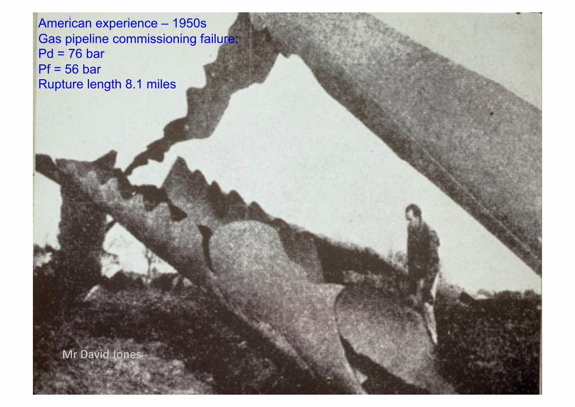
American experience – 1950s Gas pipeline commissioning failure: Pd = 76 bar Pf = 56 bar Rupture length 8.1 miles
Mr David Jones
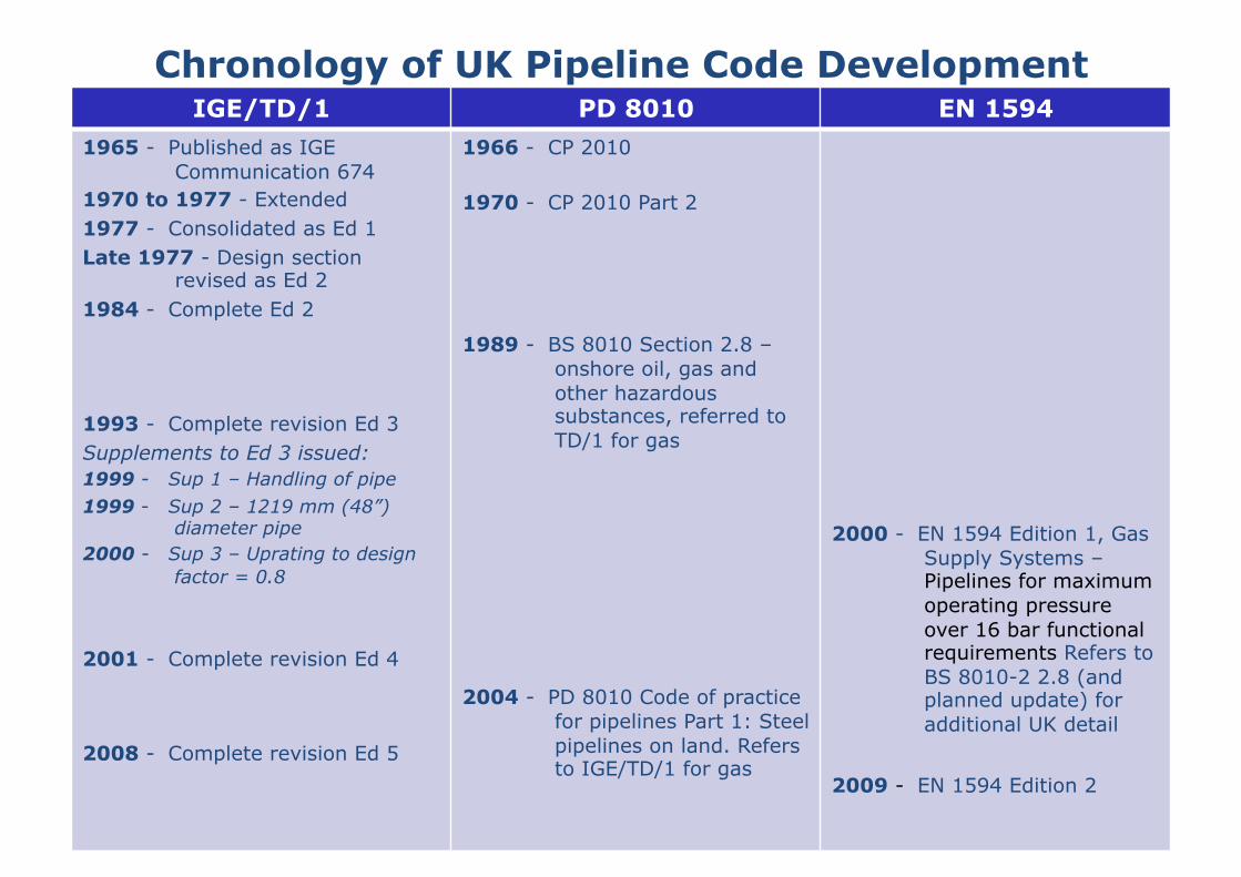
Chronology of UK Pipeline Code Development IGE/TD/1 PD 8010 EN 1594
1965 - Published as IGE Communication 674
1970 to 1977 - Extended 1977 - Consolidated as Ed 1 Late 1977 - Design section
revised as Ed 2 1984 - Complete Ed 2
1993 - Complete revision Ed 3 Supplements to Ed 3 issued: 1999 - Sup 1 – Handling of pipe 1999 - Sup 2 – 1219 mm (48”)
diameter pipe 2000 - Sup 3 – Uprating to design
factor = 0.8
2001 - Complete revision Ed 4
2008 - Complete revision Ed 5
1966 - CP 2010
1970 - CP 2010 Part 2
1989 - BS 8010 Section 2.8 – onshore oil, gas and other hazardous substances, referred to TD/1 for gas
2004 - PD 8010 Code of practice for pipelines Part 1: Steel pipelines on land. Refers to IGE/TD/1 for gas
2000 - EN 1594 Edition 1, Gas Supply Systems – Pipelines for maximum operating pressure over 16 bar functional requirements Refers to BS 8010-2 2.8 (and planned update) for additional UK detail
2009 - EN 1594 Edition 2
Principles of TD/1 - Routing and Proximity
• Takes account of the characteris?cs of developments and paMerns of popula?on in the UK
• Minimises risk to public
• Recognises there is a finite possibility of failure • Proximity requirements to limit consequences

Routing – Population density assessment
• Define assessment corridor using multiple of proximity distance – 8BPD x 1.6km
• Count buildings and numbers of people – 3 persons per dwelling
• Classify as R, S or T:- – R – population ≤ 2.5 persons per hectare – S - population > 2.5 persons per hectare – T – apply TD/3

Population density in persons per hectare :-
≤2.5 - Class 1/R DF = 0.72
>2.5 – Class 2/S, DF = 0.3

Population density in persons per hectare :-
≤2.5 - Class 1/R DF = 0.72
>2.5 – Class 2/S, DF = 0.3
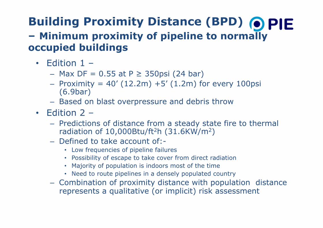
Building Proximity Distance (BPD) – Minimum proximity of pipeline to normally occupied buildings
• Edition 1 – – Max DF = 0.55 at P ≥ 350psi (24 bar) – Proximity = 40’ (12.2m) +5’ (1.2m) for every 100psi
(6.9bar) – Based on blast overpressure and debris throw
• Edition 2 – – Predictions of distance from a steady state fire to thermal
radiation of 10,000Btu/ft2h (31.6KW/m2) – Defined to take account of:-
• Low frequencies of pipeline failures • Possibility of escape to take cover from direct radiation • Majority of population is indoors most of the time • Need to route pipelines in a densely populated country
– Combination of proximity distance with population distance represents a qualitative (or implicit) risk assessment

Building Proximity Distance (BPD) – Minimum proximity of pipeline to normally occupied buildings Philosophy:- • Recognised that complete protection from the
consequences of pipeline rupture is not possible • Proximity distances do not imply zero consequences,
it is not possible to use proximities which are sufficiently great to ensure complete safety
• Emphasis is on preventing failures • Failure mode:-
– Leaks ≤ df 0.3 > Ruptures
• Consequence considerations cannot be divorced from design philosophy

Gas Industry Research – 1970s & 1980s Thermal Radiation


Wall Thickness – Minimum proximity of pipeline to normally occupied buildings
• Edition 2 – Proximities based on predictions of distance to 32 KW/m2
• R Areas :- – DF 0.72, max P = 100 bar – Failure mode – rupture
• S Areas – DF 0.3, max P = 100 bar – Failure mode:-
• WT < 9.5mm, equivalent to severance of 6” dia pipe • WT < 9.5mm with impact protection, equivalent to leak from 3” hole • 9.5mm ≤ WT < 11.9 mm, equivalent to leak from 3” hole • WT ≥ 11.9 mm, no specific proximity based on consequences,
nominal right of clearance applied

BS 8010 – Minimum Distance to Occupied Buildings
• BSI Committee extended natural gas BPD concept to other hazardous fluids
• Natural gas BPD data was supplied to BSI by IGE • QRA results for a range of hazardous fluids which were
made available at the time by pipeline operators and HSE were assessed.
• The distances to individual risk levels of 1 x 10⁻⁶ for various hazardous fluids were used to derive the substance factor, Q, given in BS 8010 table 2
• An equation was developed for the minimum distance of occupied buildings, Y, was developed for Class 1 pipelines:-

UK Gas Industry Experience – 1970s Pipe damage during construction
Mr W P Jones

Wall Thickness
0
10000
20000
30000
40000
50000
60000
70000
0 0.1 0.2 0.3 0.4 0.5 0.6 0.7 0.8
Den
tin
g F
orc
e (
Lb
s)
Wall Thickness (ins)
Quarries – Heavy Pipeline Trenching
23,000 lbf
15,000 lbf
JCB 3C
Pipe Impact with Sharp Tooth Force to Produce 0.2” dent in X60 Material
The Background and Implications of IGE/TD/1 Edition 2 - IGEM
JCB 7C

Minimising the Frequency of Gas Pipeline Failure
UK Gas Industry Research (1970s):- Leak/Rupture Behaviour of Pipeline Defects
Design Factor
0.5
1.0
1 2 Defect length/pipe radius
Design Factor
0.3
Prof Phil Hopkins

TD/1 Design Rules for Design factor and Wall Thickness Design Factor & Wall Thickness
Mr I Corder

Fracture Control
Development of minimum toughness requirements to ensure :-
– Resistance to initiation of small defects which may be sustained during life
– Most defects will leak rather than rupture – Any rupture propagation will be ductile – Arrest of propagating ductile fracture
• Avoid brittle fracture • Arrest ductile fracture
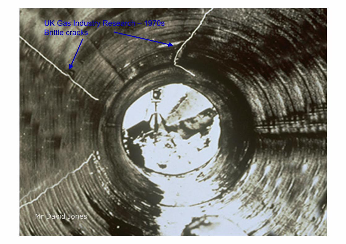
UK Gas Industry Research – 1970s Brittle cracks
Mr David Jones

Dr Julia Race
Propaga(on Arrest
Fracture Control

Material Requirements for Fracture Control
duc?le fracture arrest
DWTT test specimens
Charpy impact transi(on curve
briMle fracture avoidance
Dr Peter Boothby

TD/1 Fatigue Life
• Requirement was to design for a minimum fa?gue life • Full scale tests on pipe lengths containing largest defects
which could survive high level pre-‐service hydrotest • Lower bound on all full scale test data • Subsequently applied the generally accepted factor of safety
of 10 on life • At the ?me no?onal 40 year design life which corresponds to
15,000 daily pressure cycles • Led to TD/1 requirement that daily pressure cycles should be
limited to a stress range of 125 N/mm2

Effect of Welds on Fa(gue Life
• Stress concentra?ons occur at welds due to weld shape or defects.
Peak stress at weld toe
Nominal stress
• S-‐N approach not valid for structures containing significant crack-‐like defects
• Fracture mechanics approach required
Fa?gue crack growth from weld toe
• Addi?onal residual stresses occur
Mr David Jones
• S-‐N approach for design

TD/1 Fatigue Life
S3N = 2.93x10¹⁰
TD/1 Ed 5 Figure 4
Fracture mechanics

Pipeline Risk Management TD/1 Audit
The maximum pressure (design) of the pipeline may become limited by changes to design – specifically developments in the vicinity of the pipeline • A survey to verify compliance with design
requirements is required (Ed 2 -every 3 years, Ed 3 – 4 years, Ed 5 – 4 -6 years based on authoritative review by operator)
• Main requirement is to check population density criteria have not been exceeded (proximity infringements)
• Proximity infringements must be rectified or pressure reduced

Pipeline Risk Management Affirmation of Maximum Pressure
Where the pressure reduced by 7 bar or more for a period of 5 years, the pressure must be i) redeclared or ii) reaffirmed • Affirmation of design pressure – pressure to be
raised to this level – Pressure hold – Leak survey
• Purpose of the pressure raising – to limit accumulation of defects due to unreported 3rd party damage which have not failed at lower pressure but may fail when pressure is increased.

Pipeline Risk Management Affirmation of Maximum Pressure
• TD/1 Edition 4 required that where the maximum pressure experienced by the pipeline over a five year period had been 7 bar or more below the MOP then the pipeline MOP had to be declared at the highest pressure level experienced during this period
• TD/1 Edition 5 allows the pipeline operator to prepare a formal statement in lieu of pressure raising, this statement:
Shall confirm the pipeline and associated installations are fit for purpose at the declared MOP
Needs to be supported by the pipeline audit and an integrity assessment confirming acceptable integrity and condition monitoring of the installations
Needs to be certified by the responsible engineer.

Pipeline Risk Management – PD 8010
• Route inspection – periodically patrolled/ surveyed to defect factors that could affect safety and operation of the pipeline system
• Condition monitoring and integrity management • No requirement for pressure reaffirmation

TD/1 Risk Management
• New Design – apply standard’s requirements
• Existing Pipelines – problems encountered:-
• Land use developments • Operational changes • Changes to standards

Pipeline is no longer code compliant
Risk to people may be unacceptable
TD/1 Survey
Risk Analysis and Risk Reduc?on

Mr H Hopkins

Response to problems:-
• Pipeline diversions • Risk assessment • Recognised as societal risk situation
• Data- e.g. failure frequency • Models- consequences, effects • Risk calculations- individual, societal • Agreed Methodology
Requirements:-

Pipeline Risk Analysis
Applications:- • Proximity
infringements • Land use
developments • Operational Changes • Code updates • Uprating
Requirements • Damage & failure data • Fracture propagation
tests • Gas dispersion
experiments • Pipeline Fire
experiments and models
• Methodology • Criteria

Mr Harry Hopkins

Inner Zone 1x10-‐5
Middle Zone 1x10-‐6
Outer Zone 3x10-‐7
1x10-‐4
1x10-‐6
Individual Risk Criteria
Measure of the frequency at which an individual at a specified distance from a pipeline is expected to sustain a specified level of harm from the realisation of a specified hazard.
Individual risk contours for a given pipeline geometry, material properties and operating conditions form lines parallel to the pipeline axis. The individual risk profile plotted perpendicular to the pipeline axis reduces as the distance from the pipeline increases.

Societal Risk TD/1 Figure 20
• Measure of the relationship between frequency of an incident and the numbers of casualties that will result. • Generic societal risk relates to constant distributed population in the vicinity of the pipeline. • Site specific societal risk takes into account details of specific developments and population distributions:-
• Housing • Industrial • Commercial and leisure • Sensitive
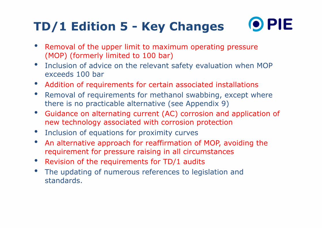
TD/1 Edition 5 - Key Changes
• Removal of the upper limit to maximum operating pressure (MOP) (formerly limited to 100 bar)
• Inclusion of advice on the relevant safety evaluation when MOP exceeds 100 bar
• Addition of requirements for certain associated installations • Removal of requirements for methanol swabbing, except where
there is no practicable alternative (see Appendix 9) • Guidance on alternating current (AC) corrosion and application of
new technology associated with corrosion protection • Inclusion of equations for proximity curves • An alternative approach for reaffirmation of MOP, avoiding the
requirement for pressure raising in all circumstances • Revision of the requirements for TD/1 audits • The updating of numerous references to legislation and
standards.