ifip aict 411 - laser beam melting for tooling applications … · · 2017-08-27keywords:...
TRANSCRIPT

G.L. Kovács and D. Kochan (Eds.): NEW PROLAMAT 2013, IFIP AICT 411, pp. 124–137, 2013. © IFIP International Federation for Information Processing 2013
Laser Beam Melting for Tooling Applications – New Perspectives for Resource-Efficient Metal Forming
and Die Casting Processes
Bernhard Müller1, Ralf Hund2, Roland Malek3, and Nancy Gerth4
1 Fraunhofer Institute for Machine Tools and Forming Technology IWU, Chemnitz, Germany 2 BRAUN CarTec GmbH, Schwalbach, Germany
3 Volkswagen AG, Wolfsburg, Germany 4 Druckguss Heidenau GmbH, Dohna, Germany
Abstract. Applying additive manufacturing technologies in the tooling sector is reaching a new level with Laser Beam Melting, since this technology allows layer-by-layer manufacturing of completely dense tool and die inserts in stan-dard high-alloyed tool steel. The technology is now ready to go beyond applica-tions in low impact processes like plastic injection moulding and enters metal working process applications like metal forming and die casting. The potential of additive manufacturing for added value in tooling applications has now been investigated for various metal working processes.
The paper presents results of research and pilot application projects to apply laser beam melting to manufacture tooling for metal forming and aluminium die casting. The paper describes the shortcomings of conventional cooling channels in metal working tools and the resulting inadequate cooling effect in critical ar-eas. The paper shows how innovative cooling systems can be implemented in metal working dies through laser beam melted die inserts. Cooling of specific die areas has been realized by placing specially designed cooling channels very close to the die cavity, targeting shorter cycle times, structural and dimensional quality improvements of manufactured metal parts and a reduction of energy consumption for cooling and idle times of forming presses and die casting ma-chines. The paper will present the achieved results for both metal working applications and point out the general potential of additive manufacturing in tooling.
Keywords: Additive Manufacturing, Laser Beam Melting, Selective Laser Melting, tooling, metal forming, die forging, press hardening, die casting, con-formal cooling, resource-efficiency.
1 Introduction
Metal forming and casting are important production technologies in Europe and worldwide. Virtually any product on the market contains formed metal parts or cast components, especially in the automotive sector. A serious challenge that manufac-turers are facing today is that clients expect ever-rising complexity and functional

Laser Beam Melting for Tooling Applications 125
integration in all products, pushing business to providing global solutions and the conventional manufacturing technologies to their limits. From a technological point of view, main problems the industry is facing are reproducibility of the production process conditions, part quality and cycle time. This asks for new knowledge of mate-rial behaviour and results in a lot of extra effort to continuously adjust processing parameters.
The emerging additive manufacturing technology laser beam melting has been identified to have the potential to realize tooling features out of standard tool steels due to its virtually unlimited freedom of design that can fulfil the desired functions in metal forming tools and casting moulds. The additive approach in building up tooling components layer by layer is the key factor to provide this freedom of design without compromises for manufacturability, cost for complexity and tool-modularity.
2 State of the Art
2.1 Press Hardening
To implement lightweight, high-strength steel parts in car bodies, the press hardening (hot sheet metal forming) technology is an emerging technology. The sheet metal is heated above the austenitization temperature (more than 800 °C) and rapidly cooled down during the forming process below 200 °C, whereby a martensitic microstructure is created [1]. This process is especially advantageous when different demands are placed on one component, for example a component that needs to have one area of higher strength or hardness and another area with higher elongation [2]. The cycle time in press hardening is determined to as much as 30% (see Figure 1) by the cooling time (holding time of closed die after forming operation before re-opening for part extraction).
Fig. 1. Exemplary illustration of the cycle time in press hardening
closing andforming
11%
open andextraction
7%
componenthandling
22%
holding/coolingtime34%
transfer tothe mold
13%
alignement13%

126 B. Müller et al.
So it was assumed that, through an optimized cooling system manufactured by la-ser beam melting, cycle time of the hot forming process can be reduced significantly. Furthermore, it was assumed that, by increasing the cooling rate, an improvement of the component’s strength can be achieved. Subsequently, through the improved me-chanical properties, a further reduction of wall thickness is getting possible. That results in a reduced need of raw material and lesser component weight and therefore in resource savings in manufacturing and use of the component. Due to the reduced cycle time, reduced energy demands and potential material savings, savings in resource consumption of up to 10 per cent per produced part were expected to be possible.
The setup of a hot forming tool (see Figure 2) is more complex than that of a con-ventional one. Mainly this is due to the fact that cooling channels must be imple-mented into punch and die. The implementation of the channels is usually done by deep drilling or a segmentation of the tool. Due to complex geometry of the tools, the cooling system design is especially demanding for tool manufacturers. The added complexity of cooling bores increases the expenses for hot forming tools. Current production effort is estimated with about one hour per meter borehole and a high consumption of resources (energy, drilling oil, compressed air, etc.). The mostly angled cooling bores also require additional preparation like mirroring and/or genera-tion of a pilot hole. Therefore, the effort of work preparation like creating CAM tool paths and drilling programs as well as defining the workflow (e.g. re-clamping) is significant.
2.2 Aluminium Die Casting
High performance aluminium casting components need high performance quality. This applies especially to innovative engine concepts which offer substantial im-provement in performance and efficiency and leads to high thermo-mechanical loads, especially on lightweight powertrain components. As a result, the die casting industry is constantly faced with new challenges. In practice, the manufacturing of compli-cated components often proves very difficult as series of casting errors such as cold shots, die marks, mends, embeddings, sink marks or heat checking can lower the qual-ity. At this point, the issue of porosity (either shrinkage or gas porosity) plays a key role. Shrinkage porosity is also known as solidification porosity and blowholes. It is the result of the casting material’s thermo-physical properties which occur during solidification and appears as volume deficits. Gas porosity can appear in the form of gas inclusions due to fluid mechanical reasons or as gas precipitation during solidifi-cation due to thermo-dynamical reasons [3].
Up to now, a selective temperature control of individual areas close to the die cav-ity could only be realized with enormous effort and limitations. Hence, the result: an insufficient attainability of the target temperature and often inadequate heat dissipa-tion in the critical areas.

Laser Beam Melting for Tooling Applications 127
Fig. 2. Tool for hot sheet metal forming
2.3 Laser Beam Melting
A way to reduce the manufacturing effort while increasing the freedom in cooling system design is the application of additive manufacturing in tool and mould making. So called rapid tooling applications emerged very soon after introduction of first layer-based rapid prototyping technologies like stereo lithography or laminated object manufacturing (LOM). Since no metallic or other durable material could be directly processed in an additive manufacturing process at that time, the need for metallic or series-material prototypes lead to first applications of layer manufactured parts as tooling like sand and investment casting patterns [4], as well as prototype and pre-series moulds for various moulding processes [5]. Direct rapid tooling was limited to very low volume production, for higher volumes only indirect processes like Keltool were applicable [6]. First research was also done toward metal forming operations with layer-manufactured tooling [7].
With further development of the selective laser sintering process (SLS) towards di-rect metal laser sintering (DMLS), it became possible to directly layer manufacture metallic tooling. Limitations of that technology were initially to be found in the nec-essary second process step of finish sintering with significant shrinkage ratios or oth-erwise the infiltration with a low melting bronze alloy. This infiltrated material was able to survive complete pre-series or low-series production up to a couple of thou-sand shots in plastics processing like injection moulding [8]. Material properties were still far away from those of standard tooling materials like hot-work steel.
This was changed with the emergence of laser beam melting technologies. Stan-dard tooling materials like 1.2709 can now be processed and completely melted rather than only superficially fused to an almost 100 per cent dense microstructure. Now it has become possible to use laser beam melting technologies to manufacture full series tooling for mass production without tool life limitations compared to conventional tool making by machining or EDM.
Additive manufacturing allows overcoming the limitations of today’s common manufacturing technology and opens up new ways for cooling of metal forming tools, e.g. in die forging [9]. Components and tools can be manufactured directly based on 3D CAD data from powdered materials such as hot work steel and built up layer-wise.

128 B. Müller et al.
For the additive manufacturing process of laser beam melting, metal powder is the starting material from which a defined contoured layer is formed. The powder is se-lectively melted layer by layer by a laser and solidifies after cooling into a solid body (see Figure 3). Therefore, the component is produced by adding layers of material and not by removing. Thanks to laser beam melting, conformal cooling is already state of the art in mould making when it comes to injection moulding. But in metal forming and die casting, tool load in terms of temperature, compression and tension is consid-erably higher and more demanding, setting a new challenge for laser beam melted tooling.
Fig. 3. Laser beam melting principle
3 The Projects
3.1 Press Hardening
Within the so-called Innovation Alliance "Green Carbody Technologies", funded by the German Federal Ministry of Education and Research and combining 60 compa-nies and research institutes in joint research to increase resource efficiency along the entire car body production chain, it has been investigated how the hot sheet metal forming process of press hardening can become more resource efficient by using in-novative laser beam melted tooling inserts. Thereby, specific die areas were getting locally tempered by arranging cooling channels very close and conformal to the cav-ity shape. Research aims were: the reduction of process cycle time, further enhance-ment of mechanical properties of hot formed metal sheets, further reduction of wall thickness and a general reduction of amount of energy used per component in its manufacturing.
The aim of the presented Innovation Alliance project was to develop and manufac-ture tool inserts with a new type of cooling system to improve resource efficiency in hot sheet metal forming. Therefore, thermo-fluidic simulation and laser beam melting were used.

After investigating curreveloped a representative deproject’s results into mass pa serial component. The deculties and potential problsurfaces and cavities to decooling channels in termscomponent.
The tool design and themanufacturing methods sucopment of the innovative, ccooling system were desigtemperature control was pro
Fig. 5. Thermal simulation: ctemperature in the tool 191 °Cthermal load (81 °C, right)
Laser Beam Melting for Tooling Applications
ent mass production, the project partners have jointly emonstrator (see Figure 4). To enable easy transfer of production, the demonstrator’s geometry is very similasign reflects a typical hot forming component and its dilems. It incorporates geometric features such as curemonstrate limitations of conventional, deep hole dril of rapid and homogeneous cooling of the sheet m
Fig. 4. Demonstrator
e cooling system design were done based on conventioch as milling and deep drilling. Parallel to this, the devconformal cooling system began. Various iterations of
gned. First proof of positive effects of the optimized tovided by numerical simulation (see Figure 5).
comparison of conventional drilled cooling channels (maximC, left) and optimized cooling channels with a significantly lo
129
de-the
ar to iffi-rved lled
metal
onal vel-the
tool
mum ower
130 B. Müller et al.
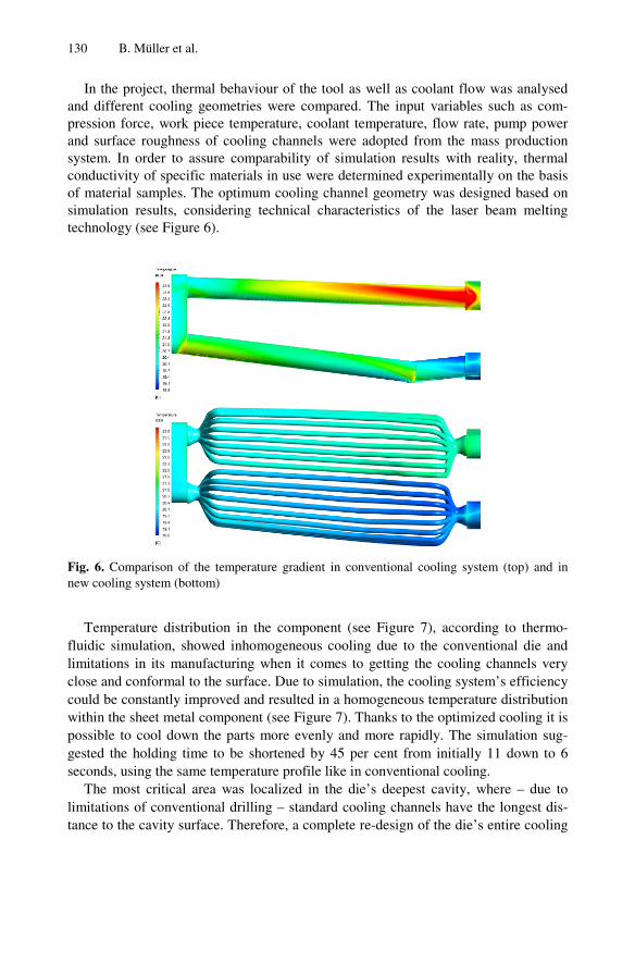
In the project, thermal band different cooling geompression force, work piece and surface roughness of csystem. In order to assure conductivity of specific maof material samples. The osimulation results, considetechnology (see Figure 6).
Fig. 6. Comparison of the temnew cooling system (bottom)
Temperature distributionfluidic simulation, showed limitations in its manufactuclose and conformal to the could be constantly improvwithin the sheet metal comppossible to cool down the gested the holding time to seconds, using the same tem
The most critical area wlimitations of conventional tance to the cavity surface.
behaviour of the tool as well as coolant flow was analymetries were compared. The input variables such as co
temperature, coolant temperature, flow rate, pump powcooling channels were adopted from the mass product
comparability of simulation results with reality, thermaterials in use were determined experimentally on the bptimum cooling channel geometry was designed based
ering technical characteristics of the laser beam melt
mperature gradient in conventional cooling system (top) and
n in the component (see Figure 7), according to therminhomogeneous cooling due to the conventional die
uring when it comes to getting the cooling channels vsurface. Due to simulation, the cooling system’s efficie
ved and resulted in a homogeneous temperature distributponent (see Figure 7). Thanks to the optimized cooling iparts more evenly and more rapidly. The simulation sbe shortened by 45 per cent from initially 11 down t
mperature profile like in conventional cooling. was localized in the die’s deepest cavity, where – due
drilling – standard cooling channels have the longest dTherefore, a complete re-design of the die’s entire cool
ysed om-wer tion mal asis
d on ting
d in
mo-and
very ncy tion it is
sug-to 6
e to dis-ling

Fig. 7. Comparison of the temtional cooling system (compooptimized cooling system (177
system was not even necedesign focused only on thein order to achieve the bestcosts it was decided to macombination of conventioning with additive manufactu
In this case, the laser beamwas applied on a conventionand heat treatment needed toof the top section. To get thstructure with conformal coafterwards sand blasted. Thmelting machine. After the tool insert (see Figure 8) waand stress relief within the la
Fig. 8. Tool insert – mil
To confirm simulation rplace on a standard hot forma variety of different parathermo-camera, temperaturfrom the trials were recorde
Laser Beam Melting for Tooling Applications
mperature distribution in the sheet metal component with convonent temperature in the critical area 335 °C, left) and with7 °C, right)
essary. The base body was left untouched and so the e critical areas around the deep cavity. Because of that t synthesis of greatest value, short production time and lanufacture the tooling insert by so-called hybrid toolingnal manufacturing technologies like milling, drilling, tuuring like laser beam melting. m melted functional structure with optimized cooling channnally milled base body (see Figure 8). Only rough machino be done on the base body to prepare it for laser beam melthe best possible bonding between base body and functio
ooling system, the upper base body surface was grinded e base body was then placed and fixated in the laser befunctional structure was applied by laser beam melting,
as removed from the machine and heat treated for hardenser beam melted section.
lled base body (left) and ready for finish-machining (right)
results, extensive forming trials were done. The trials tming press, under production-like conditions and applyameter settings. With the help of latest equipment lre sensors and computer-assisted analysis, all relevant ded and afterwards analysed.
131
ven-h the
re-and low g, a urn-
nels ning ting onal and eam the
ning
ook ying like data

132 B. Müller et al.
In a first test series, the temperature curve of the cooling process, starting from an initial temperature of 200 °C, was recorded by thermal sensors and a thermo-imaging camera. In this case, the additive manufactured tool with the new cooling system cooled down six times faster than the conventional tool with drilled cooling channels (see Figure 9). In further experiments, different holding/cooling times were run with varying cooling water flow. For temperature recording, once again thermocouples were used in the tool and thermographic imaging for the formed component. The results show that, using the new type of additively manufactured tool inserts, the hold-ing (cooling) time could be reduced by 50 per cent, which corresponds in this particu-lar case to a total cycle time reduction of 20 per cent.
Fig. 9. Thermal image of the die after 5 seconds of cooling with the conventional cooling sys-tem (temperature in the top section of the tool 142 °C, left) and with the additively manufac-tured cooling system (68 ° C, right)
3.2 Aluminium Die Casting
The newly developed V8-TFSI engine of Audi combines efficiency and high per-formance. The Biturbo presents its Premium character with a torque of up to 650Nm in a range of 1.700 up to 5.500 1/min and power outputs of up to 382kW (520PS). The engine consists of a 90°V-cylinder block and the beneath attached bedplate [10]. The component is manufactured by die casting in the alloy EN AC-Al Si9Cu3 (Fe) and is equipped with moulded crankshaft bearing caps made of spheroidal graphite iron to optimize strength, acoustics and main bearing (Figure 10).
Fig. 10. Audi bedplate V8-TFSI (view of both sides)

Laser Beam Melting for Tooling Applications 133
In the development stages, the bedplate has already been classified as a highly complex component. High customer requirements on the die cast component lead to a particularly subtle approach in terms of design and manufacturing of the component with regard to the main criteria die casting technology, die casting alloy and casting die. Therefore, the influencing factors such as material properties, process and techno-logical parameters of the die casting machine, die design under usage of an optimal gating and ventilation system were mutually modified.
The complicated bedplate was on a basic state after first series of manufacturing which has been continually developed and modified since then. The quality control, documentation and evaluation provided the basis for the on-going process analysis as well as for creation and realization of the action plan in order to optimize the compo-nent. Defects like local weak spots, shrink marks, cold runs and hot cracking are mostly thermal in nature [10] and have been improved via adaptations of the thermal management and also by precise adjustments of process parameters. Particular diffi-culties were, due to critical porosities, specifically in the area of the oil filter cartridge. Figure 11 shows the porosity’s position in the component and its magnitude.
Fig. 11. Porosity in bed plate at oil filter cartridge (right: enlarged view)
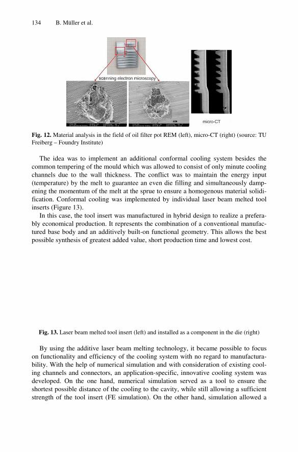
The micro porosity could not be specified unambiguously – neither by x-ray meth-ods nor computer tomography (CT) scan imaging of the whole bedplate. Material analysis – electron microscopy (REM) and micro CT [12] – provided insight (Figure 12). The pores were a hybrid of gas and solidification porosity. A minimization of the weak spot was partially attained on the conventional way by melt treatment, optimiza-tion of process parameters, optimization of process technology and periphery, optimi-zation of process monitoring and management and optimization of the casting die, in particular the gating and venting system.
The threshold value of pore sizes, especially in the oil filter cartridge zone, should prevent a possible damage of the cartridge incl. sealing ring when it comes to mount-ing or removing of the filter, a material fatigue or damage of the component and ex-clude the leakage oil. A geometrical adaptation of the component by the Audi de-signer was limited by the given installation space and was no option. Therefore, new production technologies had to be applied in order to ensure production output, qual-ity and efficiency of the bedplate.
134 B. Müller et al.
Fig. 12. Material analysis in thFreiberg – Foundry Institute)
The idea was to implemcommon tempering of the mchannels due to the wall t(temperature) by the melt tening the momentum of thefication. Conformal coolinginserts (Figure 13).
In this case, the tool insebly economical production.tured base body and an addpossible synthesis of greate
Fig. 13. Laser beam melted
By using the additive laon functionality and efficiebility. With the help of numing channels and connectordeveloped. On the one hashortest possible distance ostrength of the tool insert (
he field of oil filter pot REM (left), micro-CT (right) (source:
ment an additional conformal cooling system besides mould which was allowed to consist of only minute coolthickness. The conflict was to maintain the energy into guarantee an even die filling and simultaneously dame melt at the sprue to ensure a homogenous material solg was implemented by individual laser beam melted t
ert was manufactured in hybrid design to realize a prefe. It represents the combination of a conventional manufditively built-on functional geometry. This allows the b
est added value, short production time and lowest cost.
tool insert (left) and installed as a component in the die (right
aser beam melting technology, it became possible to foency of the cooling system with no regard to manufactumerical simulation and with consideration of existing cors, an application-specific, innovative cooling system w
and, numerical simulation served as a tool to ensure of the cooling to the cavity, while still allowing a suffici(FE simulation). On the other hand, simulation allowe
TU
the ling nput mp-lidi-tool
era-fac-best
t)
ocus ura-ool-was the
ient ed a

step-by-step optimization osimple spiral design to a cospecial care has been takensection of all individual cocross section of the coolanacross all channels and therble. Creating such a complwide contours and generoua minimum, became possib
The first additively manof the bedplate and subsequalready proved function of insert was permanently attnected to a specially water ing was gradually adjusted could be recorded. In a rangcal overheating or hypothethroughout the whole caststeps at the produced comadditional materials analysireduced and minimized to a
Fig. 14. Laser beam melted
Laser Beam Melting for Tooling Applications
of the cooling system (thermal simulation) ranging frommplex system of small channels (see figure 14). In genen in cooling system design with regard to the total cr
ooling channels combined, which should correspond to nt intake and outlet for a homogeneous flow distributrefor the most homogenous temperature distribution polex cooling system, including specific channel layout wsly rounded transitions, in order to keep pressure lossele by using additive manufacturing technology only.
nufactured, optimised tool insert was run in the casting uently the follow-up version in series production. Test rtool insert and innovative cooling system. Thereupon,
tached to the die and the cooling channels could be ctemperature control unit via conventional hoses. The coin sensitive tempering phases and a recognizable influege of only 10 Kelvin, the component area showed no crermia. This temperature range needed to remain constting process. Immediate analyses of different temper
mponents via x-ray analysis, quick sample processing is showed that gas and shrinkage porosity was significana level of permissible porosity.
tool insert (left) and installed as a component in the die (right
135
m a eral, ross the
tion ossi-with s to
die runs the
con-ool-ence riti-tant ring and ntly
t)

136 B. Müller et al.
Meanwhile, all measures have been applied in series production. The achieved re-sults could be proved and resulted in a scrap rate reduction of 10% referring to the error pattern of porosity. The innovative, additively manufactured tool insert enabled 5% less susceptibility of the process and a 3% cycle time reduction. Sustainability tests throughout the casting die’s complete life cycle have not been finalized yet. Nevertheless, the results enabled a more stable production process of the bedplate without any part design changes and therefore assured a high focus on the compo-nent’s functionality: a compact power unit, overall length limits and a high degree of integration. A rapid launch in series production could be realized [13][14].
4 Conclusions
The paper has described how metal forming and casting tool inserts can be manufac-tures by laser beam melting. A detailed in-sight has been given through case studies of innovative cooling systems, for hot sheet metal forming as well as for aluminium die casting. In the projects presented in this paper, it could be proved that laser beam melting is a well-suited technology for manufacturing highly complex moulds and tools which go beyond the limits of conventional production technologies. The unique laser beam melting technology opens up ways for new design approaches of cooling systems in metal forming tools and casting dies. This paper’s main conclusions are to be found in increasing the cooling rate in hot sheet metal forming and in improving the part quality in light metal die casting and pointed out the superiority of laser beam melting to manufacture this type of tools and tool inserts that made these promising results possible. An enormous improvement in temperature distribution within the tool as well as in the components could be achieved for both manufacturing proc-esses. Due to laser beam melting, component quality can be improved, process cycle times can be reduced significantly and therefore it is possible to increase resource efficiency of series production processes as well as to reduce the amount of energy used to manufacture each part.
References
1. Engel, B.: Hochfeste Stähle. IBU Vortragsreihe. Universität Siegen (2008), http://www.uni-siegen.de/fb11/fw/lehrstuhl/publikationen /pdf/ibu_hochfest.pdf
2. Beck, M.: Mehr als erwärmen und umformen. Industrieforum.net (2008), http://www.industrieforum.net/de/blechonlinede/oktober062008/rubrik/umformen/mehr-als-erwaermen-und-umformen
3. VDG Verein Deutscher Gießereifachleute: VDG-Merkblatt P201 – Volumendefizite von Gussstücken aus Nichteisenmetallen (Mai 2002)
4. Mueller, B., Kochan, D.: Laminated object manufacturing for rapid tooling and pattern-making in foundry industry. Computers in Industry 39/1(4), 47–53 (1999)
5. Chua, C.K., Hong, K.H., Ho, S.L.: Rapid Tooling Technology Part 2 a Case Study Using Arc Spray Metal Tooling. Advanced Manufacturing Technology 15(8), 609–614 (1999)

Laser Beam Melting for Tooling Applications 137
6. Jetley, S., Low, D.K.: A Rapid Tooling Technique Using a Low Melting Point Metal Alloy for Plastic Injection Molding. Journal of Industrial Technology 22(3), 2–8 (2006)
7. Voelkner, W.: Untersuchung der Möglichkeit des Einsatzes der Stereolithographie zum Bau von Blechumformwerkzeugen. DFG-Abschlussbericht. Institut für Produktionstechnik der TU Dresden, Dresden (1997)
8. Ferreira, J.C.: Rapid tooling of die DMLS inserts for shoot-squeeze moulding (DISA) sys-tem. Journal of Materials Processing Technology 155-156, 1111–1117 (2004)
9. Neugebauer, R., Mueller, B., Wagner, A.: Direct Rapid Tooling for Die Forging – a new challenge for Layer-Based Technologies. In: Bártolo, P.J., et al. (eds.) Innovative Devel-opments in Design and Manufacturing – Advanced Research in Virtual and Rapid Proto-typing, pp. 283–288. Taylor & Francis, Oxford (2010)
10. Königstedt, J., Aßmann, M., Brinkmann, C., Eiser, A., Grob, A., Jablonski, J., Müller, R.: Die neuen 4.0l-V8-TFSI-Motoren von Audi – die konsequente Verbindung von Effizienz und Performance. 33. Internationales Wiener Motorensymposium (2012)
11. Nogowizin, B.: Theorie und Praxis des Druckgusses. Fachverlag Schiele & Schön GmbH, Berlin (2011)
12. Eigenfeld, K., Jäckel, E.: Gutachten zur Bauteilanalyse. TU Bergakademie Freiberg, Gießerei-Institut (2012)
13. Gerth, N., Fischer, A., Hamann, I., Sauer, H., Müller, B., Rädel, T., Gebauer, M., Toeppel, T.: Prozessoptimierung im Druckgießverfahren – Laserstrahlgeschmolzener Werkzeugein-satz im Praxistest. Giesserei 100(4), 34–41 (2013)
14. Gerth, N., Sauer, H., Gebauer, M., Rädel, T.: Prozessoptimierung in der Fertigung einer Lagertraverse. MTZ Motortechnische Zeitschrift 74(06), 488–493 (2013)