ife and oecd halden reactor project - experimental ... safety presentations/19... · a key factor...
TRANSCRIPT
IFE and OECD Halden Reactor Project - Experimental Capabilities

Halden Boiling Water Reactor Design Office, Workshops, Chemistry labs, LWR loops and online instruments Hot Labs, Fuel fabrication and Re-fab.
plenum spring Ø1 mm thermocouple
end plug
Facilities for Fuels and Materials Safety Research
2

Halden Boiling Water Reactor (HBWR)
HBWR used exclusively for reactor fuel and materials safety research
• Managed and owned by the Institute for Energy Technology (IFE), Norway
• Research facility for the OECD NEA Halden Reactor Project
• Also used for contract work for utilities, vendors, licensing authorities and R&D centers
• There have been more than 400 test assembly loadings with several thousand instrumented fuel rods and material specimens
• All experimental data since 1972 are available in electronic format
3

Subcooled water
Steam out
Steam pipe drain
Subcooled water (plenum chamber)
Emergency core cooling nozzle tube
Thermocouples (or press gauge IMP. tube)
Neutron shield bolt
Positions for fuel elements
Empty positions
Control stations)
4
Characteristics of the Halden Reactor
10
16 17
31 32 33
22 23
21 11
30 12 34
35 20 25 24
39 15
29 14 26
28 27
38 37 36
19 18
13
• 20 MW heavy water reactor, 34 bar and 235oC
• Height of active core 80 cm • 1-8 E+13 n/cm2.s • Test rigs directly in HBWR
coolant have 71 mm ID • Test rigs in pressure flasks
connected to loop systems have 33 or 43-57 mm ID
• 10-11 water loops in operation at any given time
Total no. of channels: 329 Total no. fuel assemblies: 80 – 110 No. test rigs: 15 – 35 No. driver fuel rigs (6 wt% UO2): 65 – 75 No. control rods (Cd/Ag): 30

5
Loop Systems in the Halden Reactor • Test rigs placed in pressure
flasks connected to a loop • Allows testing under
simulated BWR, PWR, VVER or PHWR conditions: • Coolant pressure • Coolant temperature • Water chemistry (not VVER)
• Used for • IASCC of core internals • Corrosion studies • PCMI testing • Fuel ramp testing (to fail) • Fuel degradation tests • Dry-out and LOCA tests


7
A key factor in Halden reactor experimental work is: Making In-Pile Fuels Measurements
‘On-line’ measurements are the speciality of Halden’s experimental work: reliable instrumentation provides direct insight into phenomena while they develop
• All test assemblies are equipped with in-pile instruments to monitor fuel behavior: Pressure in fuel rods Fuel temperature Elongation of fuel and clad Change of cladding diameter
• Test assemblies create a controlled testing environment within the Halden Reactor

1% FGR release onset
8
Typical HRP Fuels Tests • Fuel (pellets) performance
• Fission gas release • Thermo-mechanical behaviour • Comparing different fuel types
• Cladding performance • Clad creep, growth, corrosion, hydriding • Comparing different cladding types
• Safety margins and criteria • Power transients - PCMI and to failure (PCI-SCC) • T-H transients – dryout / DNB • Overpressure conditions (EOL RIP) • Fuel rod behaviour under LOCA conditions • Code development and validation

Fuel Performance Research Long-term fuel tests aimed at: • determining fuel and cladding performance
under normal and extended operating conditions by monitoring through-life fuel behavior with extensive instrumentation
• generating a large database for design & licensing and used by modellers • fuel thermal conductivity, fuel and clad
dimensional stability, FGR, PCMI • Recent and future focus on:
• Gd-bearing fuels, Cr-doped fuels, VVER fuel, MOX, Th-MOX and optimised pellets for PCI resistance, fission gas retention, improved fuel thermal conductivity and higher U-235 density
Outlet turbine Outlet thermocouples Fuel thermocouple Fuel extensometer
Shroud Neutron detectors Fuel rod Expansion thermometer
Pressure transducer Inlet thermocouples Inlet turbine
Calibration valve
9

Testing thermo-mechanical and FGR behaviour of different fuels with Gd-additive
FGR (reactor power ramp to 20 MW)
Signs of densification in rods 1 and 2 Different behaviour for 8%wt Gd because T < Tthreshold
10

Fuel Cladding Performance Research Tests with cladding as the focus: • Aimed at determining cladding performance
under normal and also more demanding operating conditions
• Cladding corrosion behaviour monitored via interim inspections or EIS
• Cladding creep behaviour monitored on-line with diameter gauge
• Recent and future focus on: • Zirlo & Opt. Zirlo, E110, M5,
M-MDA, “ATF” claddings • High Li water chemistry • On-line corrosion
monitoring
11

Example: creep of M-MDA under variable stress
Recurring primary creep depends on stress change, secondary creep depends on stress level.
12

Fuels Safety Margins Research Tests with pre-irradiated fuel / segments of NPP fuel rods aimed at: • determining behavior under specific types of
operation conditions • Rod overpressure “lift-off” testing • Power transients – PCMI, FGR, PCI-SCC • Secondary degradation • Cooling transients – dry-out
• dedicated instrumentation attached to pre-irradiated fuel segments
• pre- and post irradiation examinations • data of practical use for utilities as well as for
licensing/regulatory issues
13
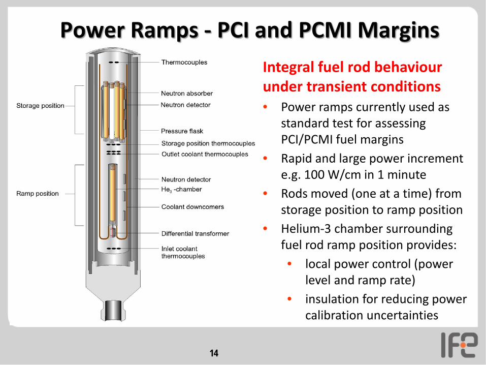
Power Ramps - PCI and PCMI Margins Integral fuel rod behaviour under transient conditions • Power ramps currently used as
standard test for assessing PCI/PCMI fuel margins
• Rapid and large power increment e.g. 100 W/cm in 1 minute
• Rods moved (one at a time) from storage position to ramp position
• Helium-3 chamber surrounding fuel rod ramp position provides: • local power control (power
level and ramp rate) • insulation for reducing power
calibration uncertainties
14

Examples from PCI / PCMI margins ramp testing Example of
failed rod visual
inspection
Large PCMI but no failure
15

Fuel secondary degradation test Pressure line Bellows To fuel rod
Water ingress
• Connected to one end of fuel rods
• Controlled water ingress by pressurizing bellows to break seal
16
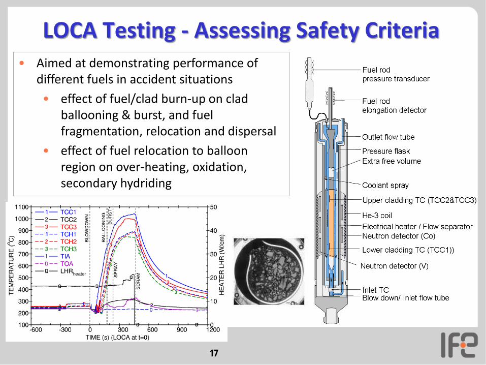
LOCA Testing - Assessing Safety Criteria • Aimed at demonstrating performance of
different fuels in accident situations • effect of fuel/clad burn-up on clad
ballooning & burst, and fuel fragmentation, relocation and dispersal
• effect of fuel relocation to balloon region on over-heating, oxidation, secondary hydriding
17

Making an overview from multiple tests: LOCA test # 2 7 6 11 10 12 13 3 5 9 4
burnup, MWd/kg 0 44.3 55.5 56 60 72.3 74.1 81.9 83 90 92
balloon strain, % 54 23 49 25 15 40 45 8 15 61 62
radio- graphy
ceramo- graphy
not y
et a
vaila
ble
fragment size coarse coarse coarse coarse
coarse & some
fine coarse & fine
coarse (& fine?)
medium & fine
medium & fine
medium & fine
medium & fine
VVER segments

19
Typical HRP Materials Tests • IASCC crack growth rate and integrated time to failure
• Environment • Stress • Microstructure
H2 addition
• Stress relaxation
• Temperature, flux, fluence • Alloy types

20
Summary of the Capabilities of the Halden Reactor
• Reactor operation dedicated to fuel and materials testing
• Reliable and versatile in-core instrumentation together with capability to implement different modes of operation
• Ability to simulate operation conditions of commercial NPPs with multiple loop systems
• Generation of directly applicable data for evaluation of performance, safety margins and safety criteria

The Halden Reactor is used for a broad spectrum of Fuels & Materials studies
high burnup, operating conditions water chemistry
FUEL CLAD Control Materials
Core Comp. Materials
Standard UO2 UO2 + additives
MOX, inert matrix Fission gas release Fuel temperature - conductivity - stored energy Fuel densification Fuel swelling
Rod pressure, lift-off Gap conductance Axial gaps (clad collapse, power peaks) SCC/PCMI
Zirconium alloys, new
ATF claddings
Creep & Growth
Failure Corrosion Crud, AOA
Guide tube bowing IRI Graphite
B4C
He release, pressure, swelling
Stainless steels Nickel based
alloys Crack initiation & Time to failure Crack growth rate (IASCC) Mechanical prop. changes Embrittlement, annealing (RPV)