iel application sections a to m
TRANSCRIPT

Grange BackUp Power Industrial Emissions Licence Application
349512/EDE/DDX/1/A 20 October 2015
46
E.1 Emissions to Atmosphere
E.1.A Details of all Point Emissions to Atmosphere
The atmospheric emission points for the power plant are listed hereunder. More comprehensive
information on emissions is provided in Table E.1 (ii). In addition, the locations of emission points are
illustrated in Figure E.1.1 Atmospheric Emissions Points.
Boiler Emissions
There will be no boiler emissions from the power plant.
Main Emissions
Exhaust gases from the 7 no. Wärtsilä 18V50DF engines gas engine will be emitted to atmosphere through
7 no. flue exhausts which will be combined into 2 no. stacks located to the north of the main building on
site. One stack will accommodate 3 no. flue exhausts and the other stack will accommodate 4 no. flue
exhausts. Both stacks will be 25 metres in height.
The power plant is expected to operate primarily on natural gas and only in very rare circumstance on
distillate oil in the event of emergency scenario or an interruption to gas supplies. There will be two main
emission points, as identified below:
� Gas Engine Stack 1 (A2-1);
� Gas Engine Stack 2 (A2-2).
The Industrial Emissions Directive specifies the emission limit values for certain categories of power plants.
In the case of the Grange BackUp Power plant facility, it should be noted that this power plant is
considered to be a ‘gas engine’ in accordance with the definitions set out in the Directive, i.e. ‘an internal
combustion engine which operates according to the Otto cycle and uses spark ignition, or in case of dual
fuel engines, compression ignition to burn fuel’. The plant is therefore required to comply with the emission
limit values for gas engines as specified in Annex V the Directive.
In relation to its operation on back up fuel, i.e. low sulphur distillate oil, it should be noted that the Directive
does not identify specific emission limit values for gas engines. In these operating scenarios the power
plant is required only to comply with the Large Combustion Plant BREF (2006) [refer Section 1.8c]. A
stated previously in this application, the plant will only operate on low sulphur distillate oil in emergency
situations and for short duration testing as required by the Commission for Energy Regulation (CER) and
EirGrid. This operating requirement is recognised in the grant of planning permission issued by South
Dublin County Council (Planning Register: SD15A/0061) which states under Condition No. 3 that ‘oil fired
power generation shall only be used in the event of emergency operation…and shall not be used for any
normal operating period’.
E. Emissions
For
insp
ectio
n pur
pose
s only
.
Conse
nt of
copy
right
owne
r req
uired
for a
ny ot
her u
se.
EPA Export 11-11-2015:00:54:10

Grange BackUp Power Industrial Emissions Licence Application
349512/EDE/DDX/1/A 20 October 2015
47
Minor Emissions
There will be six minor emission points as described hereunder:
� A3-1 Fuel Oil Storage Tank;
� A3-2 Leak Fuel Tank Vent (clean);
� A3-3 Leak Fuel Tank Vent (dirty);
� A3-4 Sludge Tank;
� A3-5 Diesel Fired Fire Fighting Pump; and
� A3-6 SCR Reagent Tank (Urea).
Minor emissions from fuel burning include Nitrogen Oxides (NOx), Carbon Monoxide (CO), Carbon Dioxide
(CO2) and particulates. Natural gas is a clean fuel with negligible sulphur and particulate matter content.
Diesel will be restricted to 0.1% Sulphur and will be of a high grade with limited particulate matter content.
Emissions to atmosphere from the minor emission sources will not be significant.
A3-1 Fuel Oil Storage Tank
In order to comply with Commission for Energy Regulation (CER) regulations low sulphur distillate oil will
be stored as a backup fuel in the event of interruption to the natural gas supply. Up to 72 hours (3 days)
maximum running capacity of diesel is required to be stored on site (approximately 2,000m³) in a bunded
tank. There is potential for very minor emission loss from the distillate oil tank for an air vent and also
during connection for refuelling. It should be noted that the storage, transfer and handling techniques will
comply with Reference Document on Best Available Techniques on Emissions from Storage (2006) and
IPC Guidance Note on Storage and Transfer of Materials for Scheduled Activities, EPA (2004). Emissions
from the fuel oil storage tank vent will therefore not be significant.
A3-2 Leak Fuel Tank Vent (clean)
Clean leak fuel is drained by gravity from the engine. The fuel is collected in a separate clean leak fuel tank
with a storage capacity of 50m³, from where it can be pumped to the main distillate fuel storage tank
(storage capacity 2000m3) and reused without separation. This tank has potential for very minor emission
losses through an air vent. However these will not be significant.
A3-3 Leak Fuel Tank Vent (dirty)
There is potential for fuel or water to spill in the hot box of the engine which will be collected and drained
by gravity to the dirty leak fuel tank which has a capacity of 80m³. This tank has potential for very minor
emission losses through an air vent. However these will not be significant.
For
insp
ectio
n pur
pose
s only
.
Conse
nt of
copy
right
owne
r req
uired
for a
ny ot
her u
se.
EPA Export 11-11-2015:00:54:10
Grange BackUp Power Industrial Emissions Licence Application
349512/EDE/DDX/1/A 20 October 2015
48
A3-4 Sludge Tank
Dirty leak fuel is drained ultimately to the sludge tank. This tank has potential for very minor emission
losses through an air vent. However these will not be significant.
A3-5 Diesel Fired Fire Fighting Pump
The firefighting pump will operate on diesel. The pump will be located within the fire pump house. The
pump will only be used in an emergency and for short duration testing, for a maximum of 30 minutes once
a week. The pump will have an electrical output of less than 100 kW.
A3-6 SCR Reagent (Urea) Tank
The most commonly used secondary emission control method for NOX is the Selective Catalytic Reduction
(SCR) technique. In the SCR system the NOX (NO and NO2) are reduced with the help of a reducing agent
such as urea which will be stored in a dedicated tank with a volume of 150m³. SCR does not produce any
liquid or solid by-products and is suitable for both liquid and gaseous fuels. This tank has potential for very
minor emission losses through an air vent. However these will not be significant.
For
insp
ectio
n pur
pose
s only
.
Conse
nt of
copy
right
owne
r req
uired
for a
ny ot
her u
se.
EPA Export 11-11-2015:00:54:10

P1 29/09/15 SHY For PlanningMMcC PK
Key to symbols
App’dCh’k’dDescriptionDrawnDateRev
RevStatus
Drawing Number
Scale at A0
Eng check
Approved
Coordination
Dwg check
Drawn
Designed
Title
Notes
Client
Reference drawings
Security
P:\Dublin\MPD\349512 - Grange Power\CAD\Figure E.1.1.dwg Sep 30, 2015 - 1:27PM hea38245
TFW
©
Figure E.1.1
Atmospheric Emissions Point
Grange Back Up Power Ltd
Others
S. Healy
M.McCarthy
Others
P.Kelly
1:200 APR
MMD-349512-N-DR-00-XX-0007
P1 STD
Mott MacDonald
South Block, Rockfield,
Dundrum, Dublin 16,
Ireland
+353 (0)1 2916700
+353 (0)1 2916747
www.mottmac.com
This document is issued for the party which commissioned it and for specific purposes connected with the captioned project only. It should not be relied upon by any other party or used for any other purpose.
We accept no responsibility for the consequences of this document being relied upon by any other party, or being used for any other purpose, or containing any error or omission which is due to an error or omission in data supplied to us by other parties.
Mott MacDonald
1:200
0 25m10m
1
2
3
4
5
6
8
9
10
11
13
16
17
18
19
20
7
14
21
15
22
23
24
25
26
1. THIS DRAWING IS TO BE READ IN CONJUNCTION WITH
ALL RELEVANT ARCHITECTS AND ENGINEERS DRAWINGS
AND SPECIFICATIONS.
2. DO NOT SCALE, USE FIGURED DIMENSIONS ONLY.
3. ANY DISCREPANCIES TO BE REPORTED TO THE
ARCHITECT.
4. ALL DIMENSIONS ARE IN MILLIMETERS.
5. ALL LEVELS ARE IN METRES RELATIVE TO ORDNANCE
SURVEY DATUM MALIN HEAD.
ENGINE HALL
ANCILLIARY TANKS, PLANT, EQUIPMENT AND BUILDINGS
EMISSION POINT
28
29
30
31
32
33
34
1
22
22
22
22
22
22
6
5
18
10
11
16
8
9
4
19
25
17
19
2423
21
26
14
3
7
20
15
2
14
17
³
³
33
34
B
0008
A
0008
A
0008
N
26
For
insp
ectio
n pur
pose
s only
.
Conse
nt of
copy
right
owne
r req
uired
for a
ny ot
her u
se.
EPA Export 11-11-2015:00:54:10

49 349512/EDE/DDX/1/A 20 October 2015
Grange BackUp Power Industrial Emissions Licence Application
TABLE E.1(ii) MAIN EMISSIONS TO ATMOSPHERE
Emission Point Ref. No:
A2-1
Source of Emission:
Engine Operating on Natural Gas
Location:
Stack No.11
Grid Ref. (12 digit, 6E,6N):
303681 E, 232116 N
Vent Details
Diameter:
Height above Ground(m):
2.77 metres 25.0 metres
Date of commencement:
TBC
Characteristics of Emission:
(i) Volume to be emitted: 80 Nm3/s (dry)2
Average/day Nm3/d Maximum/day Nm3/d
Maximum rate/hour 288,000 Nm3/h
Min efflux velocity 3108 m.sec-1
(ii) Other factors
Temperature 405oC(max) 352oC(min) 373oC(avg)
For Combustion Sources: Volume terms expressed as : � wet. √dry. ________%O2
(iii) Period or periods during which emissions are made, or are to be made, including daily or seasonal variations (start-up /shutdown
to be included):
1 All individual stacks are collected to two clusters of 4 and 3 stacks. Stack No.1 will have 4 engines in the cluster
2 20 Nm3/s (dry) for 1 no. engine which equates to 80 Nm3/s (dry) for 4 no. engines.
3 27 m/s per engine (100% engine load)
For
insp
ectio
n pur
pose
s only
.
Conse
nt of
copy
right
owne
r req
uired
for a
ny ot
her u
se.
EPA Export 11-11-2015:00:54:10

50 349512/EDE/DDX/1/A 20 October 2015
Grange BackUp Power Industrial Emissions Licence Application
Periods of Emission (avg)
4
60 min/hr 24 hr/day 365 day/yr
4 Period of emission will be as instructed by the TSO EirGrid and whilst the plant is expected to operate to meet peak demand, the hours of operation could potentially occur at any time during the day
or night.
For
insp
ectio
n pur
pose
s only
.
Conse
nt of
copy
right
owne
r req
uired
for a
ny ot
her u
se.
EPA Export 11-11-2015:00:54:10

51 349512/EDE/DDX/1/A 20 October 2015
Grange BackUp Power Industrial Emissions Licence Application
TABLE E.1(iii): MAIN EMISSIONS TO ATMOSPHERE - Chemical characteristics of the emission
Emission Point Reference Number: A2-1: Engine Operating on Natural Gas
Parameter Prior to treatment(1) Brief As discharged(1)
mg/Nm3 kg/h description mg/Nm3 kg/h. kg/year
Avg Max Avg Max of treatment Avg Max Avg Max Avg Max
NOx N/A N/A N/A N/A Selective catalytic
reduction
- 755 - - - -
SO2 N/A N/A N/A N/A SO2emissions minimised
when firing on natural gas
- 15 - - - -
CO2 N/A N/A N/A N/A Fuel Type - - - - - -
CO N/A N/A N/A N/A Combustion Control - 100 - - - -
Particulate Matter N/A N/A N/A N/A
Particulate matter
emissions minimised when
firing on natural gas
- 10 - - - -
1. Concentrations should be based on Normal conditions of temperature and pressure, (i.e. 0oC,101.3kPa). Wet/dry should be the same
as given in Table E.1(ii) unless clearly stated otherwise.
5 Calculated as NO2.
For
insp
ectio
n pur
pose
s only
.
Conse
nt of
copy
right
owne
r req
uired
for a
ny ot
her u
se.
EPA Export 11-11-2015:00:54:10

52 349512/EDE/DDX/1/A 20 October 2015
Grange BackUp Power Industrial Emissions Licence Application
TABLE E.1(ii) MAIN EMISSIONS TO ATMOSPHERE
Emission Point Ref. No:
A2-1
Source of Emission:
Engine Operating on Low Sulphur Distillate Oil6
Location:
Stack No.1
Grid Ref. (12 digit, 6E,6N):
303681 E, 232116 N
Vent Details
Diameter:
Height above Ground(m):
2.77 metres 25.0 metres
Date of commencement:
TBC
Characteristics of Emission:
(i) Volume to be emitted: 100 Nm3/s (dry)7
Average/day Nm3/d Maximum/day Nm3/d
Maximum rate/hour 360,000 Nm3/h
Min efflux velocity 8112m.sec-1
(ii) Other factors
Temperature 361oC(max) 276oC(min) 345oC(avg)
For Combustion Sources: Volume terms expressed as : � wet. √dry. ________%O2
6 it should be noted also that the Industrial Emissions Directive does not identify emission limit values for gas engines when operating on back up fuel, i.e. low sulphur distillate oil. In these operating
scenarios the power plant is required only to comply with the Large Combustion Plant BREF (2006). 7 23-25 nm3/s (dry) for 1 no. engine which equates to 100 Nm
3/s (dry) for 4 no. engines.
8 28 m/s per engine (100% engine load)
For
insp
ectio
n pur
pose
s only
.
Conse
nt of
copy
right
owne
r req
uired
for a
ny ot
her u
se.
EPA Export 11-11-2015:00:54:10

53 349512/EDE/DDX/1/A 20 October 2015
Grange BackUp Power Industrial Emissions Licence Application
(iii) Period or periods during which emissions are made, or are to be made, including daily or seasonal variations (start-up /shutdown
to be included):
Periods of Emission9
(avg)
60 min/hr 24 hr/day 365 day/yr
9 9 Period of emission will be as instructed by the TSO EirGrid and whilst the plant is expected to operate to meet peak demand, the hours of operation could potentially occur at any time during the day or night.
For
insp
ectio
n pur
pose
s only
.
Conse
nt of
copy
right
owne
r req
uired
for a
ny ot
her u
se.
EPA Export 11-11-2015:00:54:10
54 349512/EDE/DDX/1/A 20 October 2015
Grange BackUp Power Industrial Emissions Licence Application
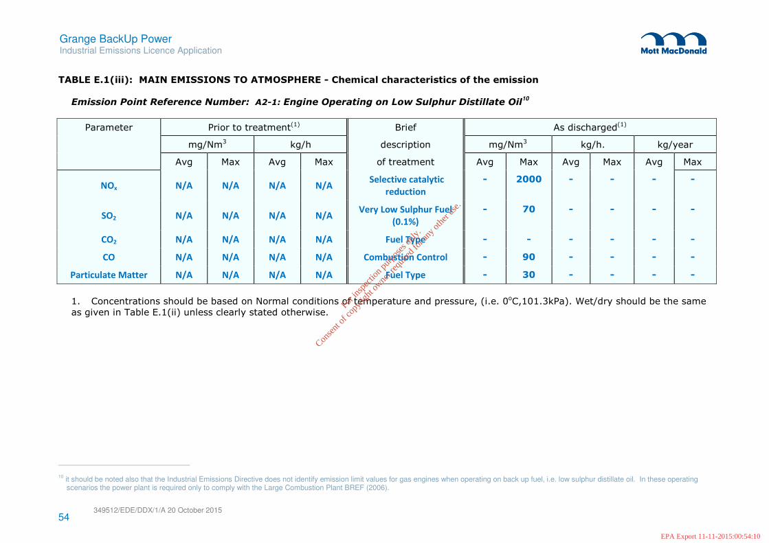
TABLE E.1(iii): MAIN EMISSIONS TO ATMOSPHERE - Chemical characteristics of the emission
Emission Point Reference Number: A2-1: Engine Operating on Low Sulphur Distillate Oil
10
Parameter Prior to treatment(1) Brief As discharged(1)
mg/Nm3 kg/h description mg/Nm3 kg/h. kg/year
Avg Max Avg Max of treatment Avg Max Avg Max Avg Max
NOx N/A N/A N/A N/A Selective catalytic
reduction
- 2000 - - - -
SO2 N/A N/A N/A N/A Very Low Sulphur Fuel
(0.1%)
- 70 - - - -
CO2 N/A N/A N/A N/A Fuel Type - - - - - -
CO N/A N/A N/A N/A Combustion Control - 90 - - - -
Particulate Matter N/A N/A N/A N/A Fuel Type - 30 - - - -
1. Concentrations should be based on Normal conditions of temperature and pressure, (i.e. 0oC,101.3kPa). Wet/dry should be the same
as given in Table E.1(ii) unless clearly stated otherwise.
10
it should be noted also that the Industrial Emissions Directive does not identify emission limit values for gas engines when operating on back up fuel, i.e. low sulphur distillate oil. In these operating scenarios the power plant is required only to comply with the Large Combustion Plant BREF (2006).
For
insp
ectio
n pur
pose
s only
.
Conse
nt of
copy
right
owne
r req
uired
for a
ny ot
her u
se.
EPA Export 11-11-2015:00:54:10

55 349512/EDE/DDX/1/A 20 October 2015
Grange BackUp Power Industrial Emissions Licence Application
TABLE E.1(ii) MAIN EMISSIONS TO ATMOSPHERE
Emission Point Ref. No:
A2-2
Source of Emission:
Engine Operating on Natural Gas
Location:
Stack No.211
Grid Ref. (12 digit, 6E,6N):
303656 E, 232117N
Vent Details
Diameter:
Height above Ground(m):
3.20 metres 25.0 metres
Date of commencement:
TBC
Characteristics of Emission:
(i) Volume to be emitted: 60 nm3/s (dry)12
Average/day Nm3/d Maximum/day Nm3/d
Maximum rate/hour 216,000 Nm3/h
Min efflux velocity 1327 m.sec-1
(ii) Other factors
Temperature 405oC(max) 352oC(min) 373oC(avg)
For Combustion Sources: Volume terms expressed as : � wet. √dry. ________%O2
(iii) Period or periods during which emissions are made, or are to be made, including daily or seasonal variations (start-up /shutdown
to be included):
11
Stack No.2 will have 3 engines in the cluster. 12
20 nm3/s (dry) for 1 no. engine which equates to 60 Nm3/s (dry) for 3 no. engines.
13 27 m/s per engine (100% engine load)
For
insp
ectio
n pur
pose
s only
.
Conse
nt of
copy
right
owne
r req
uired
for a
ny ot
her u
se.
EPA Export 11-11-2015:00:54:10

56 349512/EDE/DDX/1/A 20 October 2015
Grange BackUp Power Industrial Emissions Licence Application
Periods of Emission 14
(avg)
60 min/hr 24 hr/day 365 day/yr
14
14
Period of emission will be as instructed by the TSO EirGrid and whilst the plant is expected to operate to meet peak demand, the hours of operation could potentially occur at any time during the day or night.
For
insp
ectio
n pur
pose
s only
.
Conse
nt of
copy
right
owne
r req
uired
for a
ny ot
her u
se.
EPA Export 11-11-2015:00:54:10

57 349512/EDE/DDX/1/A 20 October 2015
Grange BackUp Power Industrial Emissions Licence Application
TABLE E.1(iii): MAIN EMISSIONS TO ATMOSPHERE - Chemical characteristics of the emission
Emission Point Reference Number: A2-2: Engine Operating on Natural Gas
Parameter Prior to treatment(1) Brief As discharged(1)
mg/Nm3 kg/h description mg/Nm3 kg/h. kg/year
Avg Max Avg Max of treatment Avg Max Avg Max Avg Max
NOx N/A N/A N/A N/A Selective catalytic
reduction
- 7515 - - - -
SO2 N/A N/A N/A N/A SO2 emissions minimised
when firing on natural gas
- 15 - - - -
CO2 N/A N/A N/A N/A Fuel Type - - - - - -
CO N/A N/A N/A N/A Combustion Control - 100 - - - -
Particulate Matter N/A N/A N/A N/A
Particulate matter
emissions minimised when
firing on natural gas
- 10 - - - -
1. Concentrations should be based on Normal conditions of temperature and pressure, (i.e. 0oC,101.3kPa). Wet/dry should be the same
as given in Table E.1(ii) unless clearly stated otherwise.
15
Calculated as NO2.
For
insp
ectio
n pur
pose
s only
.
Conse
nt of
copy
right
owne
r req
uired
for a
ny ot
her u
se.
EPA Export 11-11-2015:00:54:10

58 349512/EDE/DDX/1/A 20 October 2015
Grange BackUp Power Industrial Emissions Licence Application
TABLE E.1(ii) MAIN EMISSIONS TO ATMOSPHERE
Emission Point Ref. No:
A2-2
Source of Emission:
Engine Operating on Low Sulphur Distillate Oil16
Location:
Stack No.2
Grid Ref. (12 digit, 6E,6N):
303656 E, 232117 N
Vent Details
Diameter:
Height above Ground(m):
3.20 metres 25.0 metres
Date of commencement:
TBC
Characteristics of Emission:
(i) Volume to be emitted: 75 nm3/s (dry)17
Average/day Nm3/d Maximum/day Nm3/d
Maximum rate/hour 270,000 Nm3/h
Min efflux velocity 1884 m.sec-1
(ii) Other factors
Temperature 361oC(max) 276oC(min) 345oC(avg)
For Combustion Sources: Volume terms expressed as : � wet. √dry. ________%O2
16
It should be noted also that the Industrial Emissions Directive does not identify emission limit values for gas engines when operating on back up fuel, i.e. low sulphur distillate oil. In these operating scenarios the power plant is required only to comply with the Large Combustion Plant BREF (2006).
17 23-25 nm3/s (dry) for 1 no. one engine which equates to 75 nm
3/s (dry) for 3 no. engines
18 28 m/s per engine (100% engine load)
For
insp
ectio
n pur
pose
s only
.
Conse
nt of
copy
right
owne
r req
uired
for a
ny ot
her u
se.
EPA Export 11-11-2015:00:54:10
59 349512/EDE/DDX/1/A 20 October 2015
Grange BackUp Power Industrial Emissions Licence Application
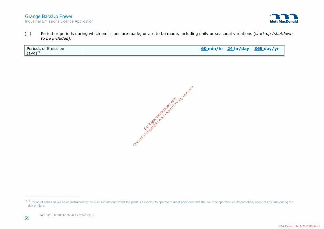
(iii) Period or periods during which emissions are made, or are to be made, including daily or seasonal variations (start-up /shutdown
to be included):
Periods of Emission (avg)
19
60 min/hr 24 hr/day 365 day/yr
19
19
Period of emission will be as instructed by the TSO EirGrid and whilst the plant is expected to operate to meet peak demand, the hours of operation could potentially occur at any time during the day or night.
For
insp
ectio
n pur
pose
s only
.
Conse
nt of
copy
right
owne
r req
uired
for a
ny ot
her u
se.
EPA Export 11-11-2015:00:54:10

60 349512/EDE/DDX/1/A 20 October 2015
Grange BackUp Power Industrial Emissions Licence Application
TABLE E.1(iii): MAIN EMISSIONS TO ATMOSPHERE - Chemical characteristics of the emission
Emission Point Reference Number: A2-2: Engine Operating on Low Sulphur Distillate Oil
20
Parameter Prior to treatment(1) Brief As discharged(1)
mg/Nm3 kg/h description mg/Nm3 kg/h. kg/year
Avg Max Avg Max of treatment Avg Max Avg Max Avg Max
NOx N/A N/A N/A N/A Selective catalytic
reduction
- 2000 - - - -
SO2 N/A N/A N/A N/A Very Low Sulphur Fuel
(0.1%)
- 70 - - - -
CO2 N/A N/A N/A N/A Fuel Type - - - - - -
CO N/A N/A N/A N/A Combustion Control - 90 - - - -
Particulate Matter N/A N/A N/A N/A Fuel Type - 30 - - - -
1. Concentrations should be based on Normal conditions of temperature and pressure, (i.e. 0oC,101.3kPa). Wet/dry should be the same
as given in Table E.1(ii) unless clearly stated otherwise.
20
It should be noted also that the Industrial Emissions Directive does not identify emission limit values for gas engines when operating on back up fuel, i.e. low sulphur distillate oil. In these operating scenarios the power plant is required only to comply with the Large Combustion Plant BREF (2006).
For
insp
ectio
n pur
pose
s only
.
Conse
nt of
copy
right
owne
r req
uired
for a
ny ot
her u
se.
EPA Export 11-11-2015:00:54:10

Grange BackUp Power Industrial Emissions Licence Application
349512/EDE/DDX/1/A 20 October 2015
61
E.3 Emissions to Surface Waters
The surface water drainage design philosophy has been prepared in accordance with the requirements of
the following technical design guidance publications:
� The Greater Dublin Strategic Drainage Study (GDSDS);
� EN 752 – Gravity Drainage Systems outside Buildings;
� CIRIA Report C697 – The SUDS Manual.
Surface water will be collected from two catchment areas within the site. The western catchment includes
the pavement in the vicinity of the fuel oil unloading bay and pumped surface water discharge from the oil
storage tank bund. Although the fuel storage tank is located within a bunded area, rainwater which falls
here is likely to be clean in the absence of an oil spill or leak. As a result, a sump and pumping
arrangement located within the bund will allow clean rainwater to be pumped into the collection system
when required. Pumping will be manually activated and will pass through a Class 1 full retention
Enviroceptor to avoid pumping contaminated water. Run-off from other paved areas and roof area (e.g.
workshop) will also drain through the Class 1 Enviroceptor. The eastern catchment consists mostly of the
engine house and pavement areas which will drain through a Bypass Separator.
It is proposed that surface water will be collected from roofed buildings via standard rainwater down pipes
while runoff from un-roofed structures will drain to the access roads where it will enter via road gullies.
Some additional gullies, acco-drains or similar collection device may be specified at detailed design stage
for large un-roofed paved areas if required. It is also proposed that gullies and drain entry points will
incorporate silt traps to remove any grit or silt which may be washed into the drainage system
The Class 1 Enviroceptor and the Bypass Separators will be fitted with visual and audible alarms to ensure
containment facilities are adequately maintained. In addition, this alarm will be linked to auto dial facilities
such that relevant staff can be alerted.
The western and eastern catchment areas will have their own surface water attenuation tanks. The
western catchment attenuation tank will have a storage volume of 80m³ and the eastern catchment
attenuation tank will have a storage capacity of 150m³.These tanks have been designed to accommodate
a 1:100 year storm event and will discharge via hydro-brakes to the existing surface water drainage system
within the Grange Castle Business Park.
All surface water generated on site will ultimately discharge to the attenuation pond to the north east of the
Business Park. It should be noted also in this respect that no development on site shall commence until
such time as a Connection Agreement has been signed with Irish Water [Planning Condition No. 4] and
proposals for surface water monitoring have been with South Dublin County Council and Inland Fisheries
Ireland [Planning Condition No. 9].
For
insp
ectio
n pur
pose
s only
.
Conse
nt of
copy
right
owne
r req
uired
for a
ny ot
her u
se.
EPA Export 11-11-2015:00:54:10

Grange BackUp Power Industrial Emissions Licence Application
349512/EDE/DDX/1/A 20 October 2015
62
The surface water emissions to the existing surface water drainage system are illustrated in Figure E.3.1
Emissions to Surface Waters. SW1 is the emission point for the eastern catchment and SW2 is the
emission point for the western catchment. More comprehensive information on the characteristics of the
emissions to surface waters are provided in Table E.3 (i).
For
insp
ectio
n pur
pose
s only
.
Conse
nt of
copy
right
owne
r req
uired
for a
ny ot
her u
se.
EPA Export 11-11-2015:00:54:10

P1 29/09/15 SHY For PlanningMMcC PK
Key to symbols
App’dCh’k’dDescriptionDrawnDateRev
RevStatus
Drawing Number
Scale at A0
Eng check
Approved
Coordination
Dwg check
Drawn
Designed
Title
Notes
Client
Reference drawings
Security
P:\Dublin\MPD\349512 - Grange Power\CAD\Figure E.3.1.dwg Oct 2, 2015 - 8:42AM hea38245
TFW
©
Figure E.3.1
Emissions to Surface Waters
Grange Back Up Power Ltd
Others
S. Healy
M.McCarthy
Others
P.Kelly
1:200 APR
MMD-349512-N-DR-00-XX-0008
P1 STD
Mott MacDonald
South Block, Rockfield,
Dundrum, Dublin 16,
Ireland
+353 (0)1 2916700
+353 (0)1 2916747
www.mottmac.com
This document is issued for the party which commissioned it and for specific purposes connected with the captioned project only. It should not be relied upon by any other party or used for any other purpose.
We accept no responsibility for the consequences of this document being relied upon by any other party, or being used for any other purpose, or containing any error or omission which is due to an error or omission in data supplied to us by other parties.
Mott MacDonald
1:200
0 25m10m
1
2
3
4
5
6
8
9
10
11
13
16
17
18
19
20
7
14
21
15
22
23
24
25
26
1. THIS DRAWING IS TO BE READ IN CONJUNCTION WITH
ALL RELEVANT ARCHITECTS AND ENGINEERS DRAWINGS
AND SPECIFICATIONS.
2. DO NOT SCALE, USE FIGURED DIMENSIONS ONLY.
3. ANY DISCREPANCIES TO BE REPORTED TO THE
ARCHITECT.
4. ALL DIMENSIONS ARE IN MILLIMETERS.
5. ALL LEVELS ARE IN METRES RELATIVE TO ORDNANCE
SURVEY DATUM MALIN HEAD.
28
29
30
31
32
33
ENGINE HALL
ANCILLIARY TANKS, PLANT, EQUIPMENT AND BUILDINGS
EMISSION POINT
1
22
22
22
22
22
22
6
5
18
10
11
16
8
9
4
19
25
17
19
2423
21
26
14
3
7
20
15
2
14
17
³
³
33
B
0008
A
0008
A
0008
A
0008
A
0008
B
0008
0008
N
26
For
insp
ectio
n pur
pose
s only
.
Conse
nt of
copy
right
owne
r req
uired
for a
ny ot
her u
se.
EPA Export 11-11-2015:00:54:10

63 349512/EDE/DDX/1/A 20 October 2015
Grange BackUp Power Industrial Emissions Licence Application
TABLE E.2(i): EMISSIONS TO SURFACE WATERS
Emission Point: SW1
Emission Point Ref. No: SW-1
Source of Emission: Surface Water Run-off
Location of discharge : Grange Castle Business Park
Grid Ref. (12 digit, 6E,6N): 303696E, 232052N
Name of receiving waters and
water body code: Irish Water Surface Water Drainage System prior to discharge to the attenuation pond to the north east of the Business Park
Flow rate in receiving waters: N/A
Available assimilative
capacity:
N/A
Emission Details:
(i) Volume to be emitted
Normal/day N/A Maximum/day N/A
Maximum rate/hour 13.68 m3
(ii) Period or periods during which emissions are made, or are to be made, including daily or seasonal variations (start-up /shutdown
to be included):
Periods of Emission (avg)21
60 min/hr 24 hr/day 365 day/yr
21
Subject to rainfall.
For
insp
ectio
n pur
pose
s only
.
Conse
nt of
copy
right
owne
r req
uired
for a
ny ot
her u
se.
EPA Export 11-11-2015:00:54:10

64 349512/EDE/DDX/1/A 20 October 2015
Grange BackUp Power Industrial Emissions Licence Application
TABLE E.2(ii): EMISSIONS TO SURFACE WATERS - Characteristics of the emission
Emission point reference number: SW1
Parameter Prior to treatment As discharged % Efficiency
Max.
hourly
average
(mg/l)
Max. daily
average
(mg/l)
kg/day kg/year Max. hourly
average (mg/l)
Max. daily
average (mg/l)
kg/day kg/year
N/A N/A N/A N/A N/A N/A N/A N/A N/A N/A
For
insp
ectio
n pur
pose
s only
.
Conse
nt of
copy
right
owne
r req
uired
for a
ny ot
her u
se.
EPA Export 11-11-2015:00:54:10

65 349512/EDE/DDX/1/A 20 October 2015
Grange BackUp Power Industrial Emissions Licence Application
TABLE E.2(i): EMISSIONS TO SURFACE WATERS
Emission Point: SW2
Emission Point Ref. No: SW-2
Source of Emission: Surface Water Run-off
Location of discharge : Grange Castle Business Park
Grid Ref. (12 digit, 6E,6N): 303607E, 232055N
Name of receiving waters and
water body code: Irish Water Surface Water Drainage System prior to discharge to the attenuation pond to the north east of the Business Park
Flow rate in receiving waters: N/A
Available assimilative
capacity:
N/A
Emission Details:
(i) Volume to be emitted
Normal/day N/A Maximum/day N/A
Maximum rate/hour 13.68 m3
(ii) Period or periods during which emissions are made, or are to be made, including daily or seasonal variations (start-up /shutdown
to be included):
Periods of Emission (avg)22
60 min/hr 24 hr/day 365 day/yr
22
Subject to rainfall.
For
insp
ectio
n pur
pose
s only
.
Conse
nt of
copy
right
owne
r req
uired
for a
ny ot
her u
se.
EPA Export 11-11-2015:00:54:10

66 349512/EDE/DDX/1/A 20 October 2015
Grange BackUp Power Industrial Emissions Licence Application
TABLE E.2(ii): EMISSIONS TO SURFACE WATERS - Characteristics of the emission
Emission point reference number: SW2
Parameter Prior to treatment As discharged % Efficiency
Max.
hourly
average
(mg/l)
Max. daily
average
(mg/l)
kg/day kg/year Max. hourly
average (mg/l)
Max. daily
average (mg/l)
kg/day kg/year
N/A N/A N/A N/A N/A N/A N/A N/A N/A N/A
For
insp
ectio
n pur
pose
s only
.
Conse
nt of
copy
right
owne
r req
uired
for a
ny ot
her u
se.
EPA Export 11-11-2015:00:54:10

Grange BackUp Power Industrial Emissions Licence Application
349512/EDE/DDX/1/A 20 October 2015
67
E.4 Emissions to Sewer
Foul wastewater from the power plant will consist of domestic effluent from the toilets, sinks, etc. on-site.
This wastewater will be discharged from the site via an appropriately sized pumping station at SE1 and will
connect to the existing foul drainage system in Grange Castle Business Park which in turn discharges to
the South Dublin County Council foul drainage system which ultimately discharges to the Ringsend
Wastewater Treatment Plant.
Process wastewater to be generated from the facility will consist of the waste stream arising from the
treatment of purified water for injection into the engine during the combustion process to control NOx
emissions. This wastewater will have a volume of approximately 0.5m3/hr and will connect to the proposed
foul drainage system at SE2.
The foul wastewater emissions to the existing Grange Castle Business Park foul drainage system are
illustrated in Figure E.4.1 Emissions to Sewer. More comprehensive information on the characteristics of
the emissions to sewer is provided in Table E.3 (ii).
For
insp
ectio
n pur
pose
s only
.
Conse
nt of
copy
right
owne
r req
uired
for a
ny ot
her u
se.
EPA Export 11-11-2015:00:54:10

P1 29/09/15 SHY For PlanningMMcC PK
Key to symbols
App’dCh’k’dDescriptionDrawnDateRev
RevStatus
Drawing Number
Scale at A0
Eng check
Approved
Coordination
Dwg check
Drawn
Designed
Title
Notes
Client
Reference drawings
Security
P:\Dublin\MPD\349512 - Grange Power\CAD\Figure E.4.1.dwg Oct 2, 2015 - 8:44AM hea38245
TFW
©
Figure E.4.1
Emissions to Sewer
Grange Back Up Power Ltd
Others
S. Healy
M.McCarthy
Others
P.Kelly
1:200 APR
MMD-349512-N-DR-00-XX-0009
P1 STD
Mott MacDonald
South Block, Rockfield,
Dundrum, Dublin 16,
Ireland
+353 (0)1 2916700
+353 (0)1 2916747
www.mottmac.com
This document is issued for the party which commissioned it and for specific purposes connected with the captioned project only. It should not be relied upon by any other party or used for any other purpose.
We accept no responsibility for the consequences of this document being relied upon by any other party, or being used for any other purpose, or containing any error or omission which is due to an error or omission in data supplied to us by other parties.
Mott MacDonald
1:200
0 25m10m
1
2
3
4
5
6
8
9
10
11
13
16
17
18
19
20
7
14
21
15
22
23
24
25
26
1. THIS DRAWING IS TO BE READ IN CONJUNCTION WITH
ALL RELEVANT ARCHITECTS AND ENGINEERS DRAWINGS
AND SPECIFICATIONS.
2. DO NOT SCALE, USE FIGURED DIMENSIONS ONLY.
3. ANY DISCREPANCIES TO BE REPORTED TO THE
ARCHITECT.
4. ALL DIMENSIONS ARE IN MILLIMETERS.
5. ALL LEVELS ARE IN METRES RELATIVE TO ORDNANCE
SURVEY DATUM MALIN HEAD.
28
29
30
31
32
33
34
ENGINE HALL
ANCILLIARY TANKS, PLANT, EQUIPMENT AND BUILDINGS
EMISSION POINT
1
22
22
22
22
22
22
6
5
18
10
11
16
8
9
4
19
25
17
19
2423
21
26
14
3
7
20
15
2
14
17
33
34
B
0008
A
0008
A
0008
A
0008
A
0008
B
0008
0008
N
26
For
insp
ectio
n pur
pose
s only
.
Conse
nt of
copy
right
owne
r req
uired
for a
ny ot
her u
se.
EPA Export 11-11-2015:00:54:10
68 349512/EDE/DDX/1/A 20 October 2015
Grange BackUp Power Industrial Emissions Licence Application
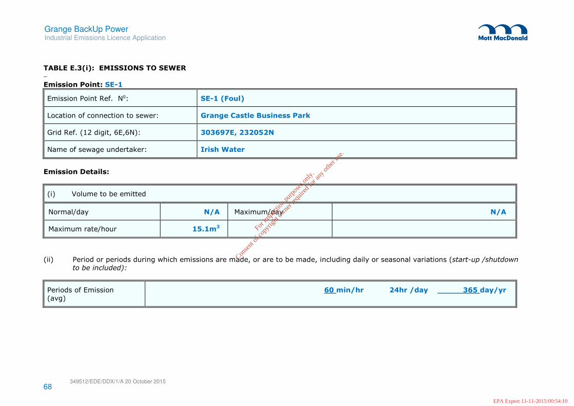
TABLE E.3(i): EMISSIONS TO SEWER − Emission Point: SE-1
Emission Point Ref. No: SE-1 (Foul)
Location of connection to sewer: Grange Castle Business Park
Grid Ref. (12 digit, 6E,6N): 303697E, 232052N
Name of sewage undertaker: Irish Water
Emission Details:
(i) Volume to be emitted
Normal/day N/A Maximum/day N/A
Maximum rate/hour 15.1m3
(ii) Period or periods during which emissions are made, or are to be made, including daily or seasonal variations (start-up /shutdown
to be included):
Periods of Emission
(avg)
60 min/hr 24hr /day 365 day/yr
For
insp
ectio
n pur
pose
s only
.
Conse
nt of
copy
right
owne
r req
uired
for a
ny ot
her u
se.
EPA Export 11-11-2015:00:54:10

69 349512/EDE/DDX/1/A 20 October 2015
Grange BackUp Power Industrial Emissions Licence Application
TABLE E.3(ii): EMISSIONS TO SEWER - Characteristics of the emission
Emission point reference number: SE-1
Parameter Prior to treatment As discharged % Efficiency
Max.
hourly
average
(mg/l)
Max. daily
average
(mg/l)
kg/day kg/year Max. hourly
average (mg/l)
Max. daily
average (mg/l)
kg/day kg/year
BOD - - - - - 20 - - -
Suspended Solids - - - - - 30 - - -
For
insp
ectio
n pur
pose
s only
.
Conse
nt of
copy
right
owne
r req
uired
for a
ny ot
her u
se.
EPA Export 11-11-2015:00:54:10

70 349512/EDE/DDX/1/A 20 October 2015
Grange BackUp Power Industrial Emissions Licence Application
TABLE E.3(i): EMISSIONS TO SEWER − Emission Point: SE-2
Emission Point Ref. No: SE-2 (Process Wastewater)
Location of connection to sewer: Grange Castle Business Park
Grid Ref. (12 digit, 6E,6N): 303598E, 232079N
Name of sewage undertaker: Irish Water
Emission Details:
(i) Volume to be emitted
Normal/day N/A Maximum/day N/A
Maximum rate/hour 0.5m3
(ii) Period or periods during which emissions are made, or are to be made, including daily or seasonal variations (start-up /shutdown
to be included):
Periods of Emission
(avg)
60 min/hr 24hr /day 365 day/yr
For in
spec
tion p
urpo
ses o
nly.
Conse
nt of
copy
right
owne
r req
uired
for a
ny ot
her u
se.
EPA Export 11-11-2015:00:54:10

71 349512/EDE/DDX/1/A 20 October 2015
Grange BackUp Power Industrial Emissions Licence Application
TABLE E.3(ii): EMISSIONS TO SEWER - Characteristics of the emission
Emission point reference number: SE-2
Parameter Prior to treatment As discharged % Efficiency
Max.
hourly
average
(mg/l)
Max. daily
average
(mg/l)
kg/day kg/year Max. hourly
average (mg/l)
Max. daily
average (mg/l)
kg/day kg/year
pH - - - - - 6-9 - - -
BOD - - - - - 25 - - -
Suspended Solids - - - - - 35 - - -
Nitrate (as N) - - - - - 10 - - -
Ammonia (as N) - - - - - 5 - - -
Chloride - - - - - 350 - - -
Mineral Oil - - - - - 20 - - -
Total Phosphorus (as P) - - - - - 2 - - -
For
insp
ectio
n pur
pose
s only
.
Conse
nt of
copy
right
owne
r req
uired
for a
ny ot
her u
se.
EPA Export 11-11-2015:00:54:10

Grange BackUp Power Industrial Emissions Licence Application
349512/EDE/DDX/1/A 20 October 2015
72
E.5 Noise Emissions
A noise impact assessment was undertaken as part of the planning application for the power plant to
determine the noise levels being emitted to the surrounding environment from the power plant. More
detailed information noise impact assessment is provided in Attachment I.7 Noise Impacts.
As part of the impact assessment, a baseline noise monitoring survey was carried out. This survey
concluded that the existing environment was not classified as a ‘Quiet Area’ or an ‘Area of Low
Background Noise’, as the average daytime LA90 was not less than or equal to 40dB; the average evening
time LA90 was not less than or equal to 35dB; and the average night-time LA90 was not less than or equal
to 30dB. The existing noise environment was therefore considered to be elevated which, at the time of the
survey, was characterised mostly by traffic, construction noise and industrial noise originating from within
the Grange Castle Business Park.
Noise impacts were predicted at nearby receptors using the CadnaA noise prediction program which
calculates noise levels in accordance with ISO 9613-2: Attenuation of Sound Propagation Outdoors:
General Method of Calculation, International Organization for Standardisation (1996). This assessment
took into consideration the existing baseline noise in the environment and assessed the potential impacts
against nationally and internationally accepted criteria and noise limits. The noise prediction programme
models the spreading of sound with distance, the absorption of sound by ground and air, the effects of
topography and screening by buildings. The following assumptions were made when creating the noise
model:
� The equipment comprising the power plant and its auxiliary machinery was modelled as a number of
point sources located in space above the ground without any physical surfaces. This means that noise
emissions would, in effect, be able to pass through the machinery. Such an approach is expected to
be conservative and is considered to be a worst case scenario modelling exercise.
� The noisier elements of the plant are identified on Figure E.5.1 Noise Emissions and include:
– 2 no. engine exhaust stacks (N1 and N2) which incorporate 7 no. flue stacks in total;
– The engine hall (building) [N3] which includes the following noise sources:
– 7 no. Wärtsilä 50DF engines;
– 7 no. ventilation inlet room;
– 7 no. ventilation outlet fan;
– 42 no. cooling radiators.
Table E.5 (i) provides more comprehensive information on the above noise emissions. It should be noted
that the input data to the model for each noise source included:
� Noise source locations including height, directivity etc;
� Source Noise Emissions – The A-weighted sound power levels for each source between frequencies
31.5Hz and 8kHz;
For
insp
ectio
n pur
pose
s only
.
Conse
nt of
copy
right
owne
r req
uired
for a
ny ot
her u
se.
EPA Export 11-11-2015:00:54:10

Grange BackUp Power Industrial Emissions Licence Application
349512/EDE/DDX/1/A 20 October 2015
73
� Working Hours – The model allows the user to define daytime, evening time and night-time periods, so
that noise levels can be predicted for each period. For the purposes of this assessment, in order to
predict the maximum possible noise levels, all of the noise sources were assumed to run continuously
during the day, evening and night-time. As the plant will not be operated continuously and will only be
operated when there is a requirement for additional electricity in the grid, assuming a continuous
operation is a very conservative approach. The model did however; assume different fan speeds for
the different time periods of the day.
� Location of sensitive receptors;
� Ground Conditions – The ground at the site and surroundings was assumed to be hard and reflecting.
This gives a conservative approach as there are areas surrounding the site which consist of grassland
which will absorb sound waves, thus reducing sound level from the proposed facility at the nearest
sensitive receptors.
Mitigation would typically comprise the following items:
� Design, procurement and installation of equipment to relevant industry standards (IS, EN etc.);
� Specification of maximum noise limit criteria for equipment in procurement contracts, including the
absence of tonal/impulsive components in external equipment;
� Inspection and maintenance of equipment as part of preventive maintenance programme to ensure
continued normal operation and minimise any noise issues occurring;
� Restricting any specific noisy activities which could impact on ambient noise levels (e.g. testing of
equipment) to daytime hours only;
� Restricting deliveries/shipments to daytime hours only.
� Periodic noise monitoring in accordance with the site’s Industrial Emissions Licence.
Overall therefore, with appropriate mitigation, operational noise levels at nearby noise sensitive receptors
would not exceed typical daytime, evening time and night time industrial emissions licence limit criteria and
would not be expected to be significant.
For
insp
ectio
n pur
pose
s only
.
Conse
nt of
copy
right
owne
r req
uired
for a
ny ot
her u
se.
EPA Export 11-11-2015:00:54:10

P1 29/09/15 SHY For PlanningMMcC PK
Key to symbols
App’dCh’k’dDescriptionDrawnDateRev
RevStatus
Drawing Number
Scale at A0
Eng check
Approved
Coordination
Dwg check
Drawn
Designed
Title
Notes
Client
Reference drawings
Security
P:\Dublin\MPD\349512 - Grange Power\CAD\Figure E.5.1.dwg Sep 30, 2015 - 12:40PM hea38245
TFW
©
Figure E.5.1
Noise Emissions
Grange Back Up Power Ltd
Others
S. Healy
M.McCarthy
Others
P.Kellly
1:200 APR
MMD-349512-N-DR-00-XX-0010
P1 STD
Mott MacDonald
South Block, Rockfield,
Dundrum, Dublin 16,
Ireland
+353 (0)1 2916700
+353 (0)1 2916747
www.mottmac.com
This document is issued for the party which commissioned it and for specific purposes connected with the captioned project only. It should not be relied upon by any other party or used for any other purpose.
We accept no responsibility for the consequences of this document being relied upon by any other party, or being used for any other purpose, or containing any error or omission which is due to an error or omission in data supplied to us by other parties.
Mott MacDonald
1:200
0 25m10m
1
2
3
4
5
6
8
9
10
11
13
16
17
18
19
20
7
14
21
15
22
23
24
25
26
1. THIS DRAWING IS TO BE READ IN CONJUNCTION WITH
ALL RELEVANT ARCHITECTS AND ENGINEERS DRAWINGS
AND SPECIFICATIONS.
2. DO NOT SCALE, USE FIGURED DIMENSIONS ONLY.
3. ANY DISCREPANCIES TO BE REPORTED TO THE
ARCHITECT.
4. ALL DIMENSIONS ARE IN MILLIMETERS.
5. ALL LEVELS ARE IN METRES RELATIVE TO ORDNANCE
SURVEY DATUM MALIN HEAD.
ENGINE HALL
ANCILLIARY TANKS, PLANT, EQUIPMENT AND BUILDINGS
28
29
30
31
32
33
34
1
22
22
22
22
22
22
6
5
18
10
11
16
8
9
4
19
25
19
2423
21
26
14
3
7
20
15
2
14
17
³
³
33
34
B
0008
A
0008
A
0008
A
0008
A
0008
B
0008
0008
N
26
For
insp
ectio
n pur
pose
s only
.
Conse
nt of
copy
right
owne
r req
uired
for a
ny ot
her u
se.
EPA Export 11-11-2015:00:54:10

74 349512/EDE/DDX/1/A 20 October 2015
Grange BackUp Power Industrial Emissions Licence Application
Table E.5(i): NOISE EMISSIONS - Noise sources summary sheet
Source
Emission
point
Ref. No
Equipment
Ref. No
Sound
Pressure1
dBA at
reference
distance
Octave bands (Hz)
Sound Pressure1 Levels dB(unweighted) per band Impulsiv
e or
tonal
qualities
Periods of
Emission2
31.5 63 125 250 500 1K 2K 4K 8K
Exhaust Gas Stack 1
N1 N/A N/A 143 140 133 129 123 122 131 135 - No Continuous
Exhaust Gas Stack 2
N2 N/A N/A 143 140 133 129 123 122 131 135 - No Continuous
Engine hall (building) – incorporating below:
N3 N/A
Engine
(7 no.)
N/A 115d(B) at
1 metre
117 123 121 122 124 123 125 125 119 No Continuous
Ventilation Room
(7 no.)
N/A N/A - 109 105 109 108 107 107 107 103 No Continuous
Ventilation Outlet
(7 no.)
N/A N/A - 110 107 109 108 105 105 105 101 No Continuous
6 Fan Cooling
Radiator (day)
(7 no.)
N/A N/A 88 88 86 86 83 76 69 68 No Continuous
6 Fan Cooling
Radiator
(evening / night)
(42 no.)
N/A N/A - 84 84 82 82 79 72 65 64 No Continuous
For
insp
ectio
n pur
pose
s only
.
Conse
nt of
copy
right
owne
r req
uired
for a
ny ot
her u
se.
EPA Export 11-11-2015:00:54:10