ieeetransactionsonpowerdelivery,vol.31,no.4,august2016...
TRANSCRIPT
IEEE TRANSACTIONS ON POWER DELIVERY, VOL. 31, NO. 4, AUGUST 2016 1787
Fault Location Using Sparse SynchrophasorMeasurement of Electromechanical-Wave
OscillationsAhad Esmaeilian, Student Member, IEEE, and M. Kezunovic, Fellow, IEEE
Abstract—This paper presents a novel system-wide fault-lo-cation method for transmission lines utilizing electromechan-ical-wave oscillation propagation phenomena. The method usessynchrophasor measurements during disturbances obtainedfrom phasor measurement units sparsely located in the network.The method determines the time of arrival of electromechan-ical waves propagating from the fault point to sparsely locatedphasor mesaurement units. By taking the speed of electromechan-ical-wave propagation as well as topology of the network intoaccount, the method is able to detect the faulty line. Finally, byadding fictitious buses inside the faulty line and applying a binarysearch method, the location of fault is accurately pinpointed. Themain advantage of the proposed method is the use of a limitednumber of PMUs which reduces the cost of implementation. Themethod was developed in MATLAB and tested with the IEEE118-test system. Test results reveal the high accuracy of the methodin detecting and locating faults.Index Terms—Electromechanical-wave propagation, fault de-
tection, fault location, phasor measurement units (PMUs), powersystem faults, synchrophasor measurement, wide-area measure-ments.
I. INTRODUCTION
P OWER system is subjected to faults caused by various rea-sons such as different weather condition, animal or human
contacts, vegetation contacts, etc. Once circuit breakers clearthe fault following relays trip command, the fault point must bedetermined and proper action taken to expedite troubleshootingand minimize repair time [1].Various fault location methods have been proposed in
literature [2]–[23]. Single-end impedance based fault loca-tion methods are considered the most conventional scheme[2]–[8]. These methods utilize power frequency componentof single-end voltage and (or) current measurements to locatefaults on transmission lines. The main advantage of suchmethods is the simplicity and low cost of implementation.However, their accuracy might be affected by different factors,such as infeed current from remote end, fault resistance, varia-
Manuscript received June 30, 2015; revised September 26, 2015 andNovember 30, 2015; accepted December 15, 2015. Date of publicationDecember 29, 2015; date of current version July 21, 2016. Paper no.TPWRD-00831-2015.The authors are with the Department of Electrical and Computer Engineering,
Texas A&MUniversity, College Station, TX 77843-3128 USA (e-mail: [email protected]; [email protected]).Color versions of one or more of the figures in this paper are available online
at http://ieeexplore.ieee.org.Digital Object Identifier 10.1109/TPWRD.2015.2510585
tion of source impedance, loading conditions or fault incidenceangle.Several methods were developed using unsynchronized
two-end measurements [9]–[13]. In [9], post fault voltage andcurrent phasor measurements are used to locate faults. Themethod is applicable even if line parameters are unknown.In [10], symmetrical components theory is used to formulatefault location scheme. The method proposed in [11] is basedon voltage magnitude at fault point and does not require phaseangles. In [14], a time-domain method based on synchronizedsampling of the voltage and current data from the two ends ofthe line is proposed. The line model equations are then solvedto build the voltage and current profiles to accurately locatethe fault. Improving the line model considering distributed lineparameters led to more accurate results in [15]. In [16], themethod proposed in [15] was modified to reduce the samplingrate from 20 kHz to 1 kHz. The main advantage of the men-tioned two-end fault location methods comparing to single-endmethods is their higher accuracy in locating faults. However,availability of measurements through the entire network mightnot be feasible due to the cost and installation concerns forforeseeable future [1]. Hence, a sparse measurements basedfault location method could be more practical due to its lowimplementation cost.In recent decades, development of phasor measurement
units (PMUs) introduced various synchrophasor based methods[17]–[20]. In [17], [18], Clarke transformation is applied tothe synchronized voltage and current phasors aligned with adiscrete Fourier transform-based algorithm to calculate thelocation of fault. Another fault detection/location techniqueis presented in [19], [20] with consideration of arcing faultdiscrimination based on synchronized fundamental phasormeasurements. In [21], a bus-impedance matrix was utilizedto calculate fault point with access to limited synchronizedmeasurements at two remote buses in the network.Several methods utilize electromagnetic transient propaga-
tion in power system and are known as travelling wave basedmethods [22]–[25]. The method proposed in [22], [23] is basedon measuring time of arrival (ToA) of electromagnetic trav-eling waves which propagate from the fault point to sparselylocated synchronized measurement devices. Then, an optimiza-tion method is applied to calculate the location of fault. In [24],a wide area traveling wave based method is proposed which de-termines faulty line and distance to fault by analyzing the trav-eling wave propagation times using the extended double end
0885-8977 © 2015 IEEE. Personal use is permitted, but republication/redistribution requires IEEE permission.See http://www.ieee.org/publications_standards/publications/rights/index.html for more information.
1788 IEEE TRANSACTIONS ON POWER DELIVERY, VOL. 31, NO. 4, AUGUST 2016
method. In [25], a traveling wave principle along with two graphtheory-based lemmas is deployed to sectionalize power systemand locate faults within suspected sections. Despite the high ac-curacy of travelling wave based methods, they require measure-ment device with high sampling rate to capture electromagnetictransient which increase cost of implementation.The method proposed in this paper is based on detection of
ToA of electromechanical-wave oscillation propagates in powersystem. Despite electromagnetic traveling wave based methods,the proposed method relies on sparse PMU measurements, andcan be practically used by utilities without requiring expen-sive dedicated high sampling rate devices. Section 2 gives thebackground theory while Section 3 explains the methodology.The results from testing are given in Sections 4 and 5 givesconclusions.
II. BACKGROUND THEORY
A. Electromechanical-Wave Propagation Phenomena
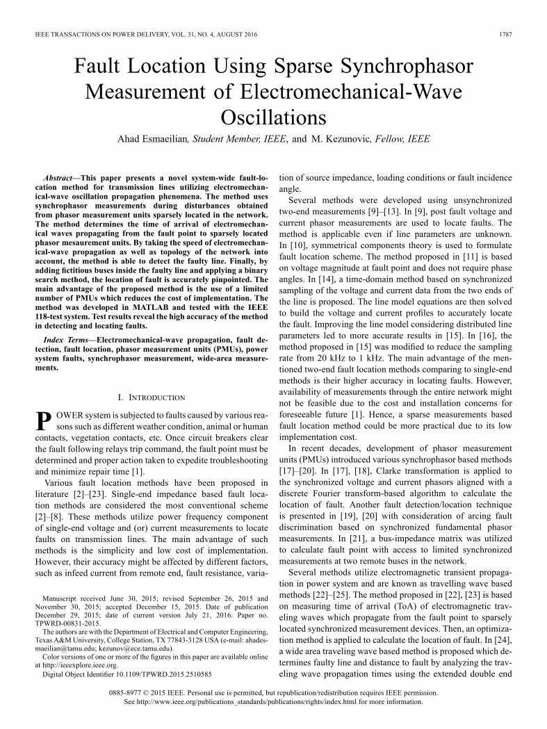
When a disturbance occurs on a transmission line, electricalpower flow changes in the network. This leads to a mismatchbetween electrical and mechanical torque of generators locatedin the vicinity. Therefore, each generator rotor angle changesto compensate the mismatch. Following the generators' rotorangle oscillations, the adjacent buses also encounter changes intheir generators' rotor angle which again causes a mismatch inthe electrical torque of the adjacent generators. In this fashion,the oscillation known as the electromechanical-wave propaga-tion is “seen” throughout the entire network. Electromechan-ical oscillations could be detected by monitoring phasor angleof bus voltages and characterized with much lower frequency(0.1–10.0 Hz) than electromagnetic transients ( kHz) [26].To illustrate the concept, a simple power-system model in theform of a ring is used. Fig. 1(a) shows the 64-generator ringsystem introduced in [26], which comprises 64 identical seri-ally connected generators through identical transmission lines,forming a ring. The initial bus angles are evenly distributed from0 to 360 degrees by steps equal to degrees.Due to homogeneity and ring shape of the 64-bus system, itis well-suited to study basic aspects of electromechanical-wavepropagation phenomena. Fig. 1(b) shows the phasor angle of64-buses (in radian) with respect to time of a given disturbanceoccurring at bus 16 at . Following the change in the angleof bus 16 shown by the dashed line in Fig. 1(b), the other gen-erators react in a similar fashion, but with a certain time delay.Plotting all the bus angles together, this time delay can be rep-resented as a wave modulated on buses' phasor angles, whichtravels away from the disturbance source into the network at afinite speed.
B. Continuum Modeling
Applying differential algebraic equations (DAEs) is the con-ventional way of modeling electromechanical-wave propaga-tion in power system. Due to complexity, this approach couldbe time consuming and the result would be hard to analyzefor large networks. Therefore, researchers introduced a much
Fig. 1. Understanding electromechanical-wave propagation. (a) 64-generatorring system, (b) Bus angle modulation following a fault at bus 16 at .
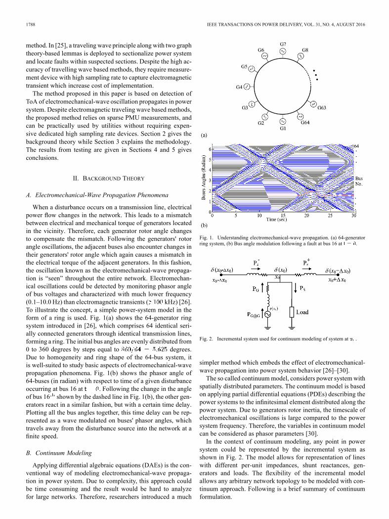
Fig. 2. Incremental system used for continuum modeling of system at .
simpler method which embeds the effect of electromechanical-wave propagation into power system behavior [26]–[30].The so called continuummodel, considers power system with
spatially distributed parameters. The continuum model is basedon applying partial differential equations (PDEs) describing thepower systems to the infinitesimal element distributed along thepower system. Due to generators rotor inertia, the timescale ofelectromechanical oscillations is large compared to the powersystem frequency. Therefore, the variables in continuum modelcan be considered as phasor parameters [30].In the context of continuum modeling, any point in power
system could be represented by the incremental system asshown in Fig. 2. The model allows for representation of lineswith different per-unit impedances, shunt reactances, gen-erators and loads. The flexibility of the incremental modelallows any arbitrary network topology to be modeled with con-tinuum approach. Following is a brief summary of continuumformulation.
ESMAEILIAN AND KEZUNOVIC: FAULT LOCATION USING SPARSE SYNCHROPHASOR MEASUREMENT 1789
In Fig. 2, the net real electrical power flow at point canbe written as (1), shown at the bottom of the page, whererepresents the phase angle of voltage at . R, X and Z representresistance, reactance and impedance of the branch, respectively.Using Taylor series expansion about , and disregarding higherorder terms we get:
(2)
The real power produced at the generator terminal is deter-mined by (3), shown at the bottom of the page. The real powerdelivered to the point by the generator is given by (4), shownat the bottom of the page, where and represent con-ductance and susceptance of a generator. By conservation ofpower, the summation of power at a region must be zero, whichimplies:
(5)
where is the net real power flow at is real power de-livered by generator and is the real power consumed by theload. Plugging (2), (3) and (4), shown at the bottom of the page,into (5), we obtain:
(6)
which is known as continuum equivalent of load flow equationsof the power system.On the other hand, the internal generator phase angle dy-
namics are modeled using:
(7)
where and are the generator inertia and dampingconstant and is the mechanical power of a generator.Plugging (3) into (7), we obtain (8), shown at the bottom of the
page, which is known as continuum equivalent of swing equa-tions of the power system. The simulation studies of this paperwere carried out using continuum PDE equations (6) and (8).
III. FAULT LOCATION METHODOLOGY
As mentioned earlier, electromechanical wave originated fol-lowing a disturbance travels with finite velocity in a given net-work. Since these waves propagate through different paths, theyreach remote buses with distinct time delays which depend oneach path length and propagation speed of wave through thatpath. Therefore, one can determine the fault location by usingToA measurements at various locations along with supportinginformation to determine each path's length and speed of prop-agation through that path.The method proposed in this paper detects ToA of electro-
mechanical waves modulated on phasor angle of voltage at se-lected buses where PMUs are available. Then the well-knownDijkstra's shortest path algorithm [31] is deployed combinedwith several mathematical steps to detect the faulty line. Finallylocation of the fault will be determined inside faulty line usingbinary search method. Fig. 3 shows the implementation struc-ture of the proposed method. Phasor measurements at certainsubstations throughout entire network can be captured by PMUsor any other IED devices located in that substation, which canmeasure and report GPS synchronized phasors. The measure-ments are then transferred to the control center where phasordata concentrator receives data from all PMUs and stores themin real-time database. The database provides input data to theproposed method. The details of the methodology are explainednext.
A. ToA and Fault Type DetectionThe proposed Artificial Neural Network (ANN) method de-
tects ToA of electromechanical wave modulated on phase angleof voltage based on analyzing the first swing of the phase angleat buses where PMUs are installed. One time calculation uti-lizing numerous training data sets on ANN implemented usingMATLAB ANN toolbox led to an accurate ToA detector.
(1)
(3)
(4)
(8)

1790 IEEE TRANSACTIONS ON POWER DELIVERY, VOL. 31, NO. 4, AUGUST 2016
Fig. 3. Fault location method implementation overview.
Fig. 4. The network structure of the back propagation neural network modelused in ToA detector.
To develop the ToA detector, supervised training is used totrain the ANN. Fig. 4 shows the overall structure of deployedANN. To differentiate between faults and other disturbancesas well as different types of fault, three types of input signalswere defined in the input layer. The phase angles of each threephase voltages, as well as their first and second time deriva-tives were selected as inputs. The inputs and desired outputswere compared in a hidden layer and errors are then propagatedback through the system. We calculated the performance of thesystem in terms of number of neurons in the hidden layer, andselected 4 hidden neurons as it provides the best result. The backpropagation algorithm causes the ANN system to tweak weightswhich control the neural network [32]. This process occurs con-tinually till the weights are adjusted within a defined threshold.The applied multilayer perceptron neural network with backpropagation algorithm used in this study is one of most commonANNmethod applied in power system. The desired output of the
ANN is the event type and ToA of the electromechanical wavemodulated on voltage phase angle.In the ANN training process, a set of 2000 events were created
within IEEE 118 bus test system [33]. In the training process,all lines are considered to be in service. Training scenarios in-clude generator and load outages, various types of faults withdifferent fault resistance at different locations. Then, another setof 500 previously unseen randomly generated event scenarios(ratio of unseen test cases to trained cases is equal to 0.25) werecreated to test and validate ANN-based ToA and fault type de-tector. Since the nature of electromechanical-wave oscillationpropagation and its related phase angle modulation is same fordifferent networks, the ANN based ToA detector can be usedfor any given network.
B. Detection of Faulty LineOnce the ToA of electromechanical-wave oscillation is ob-
tained at selected buses where PMUs are installed, it can beused to determine the faulty line. Several mathematic steps asdescribed below must be deployed before the faulty line couldbe detected.1) Computation of Line Propagation Delay: As previously
stated in Section II, the speed of electromechanical-wave prop-agation is quite lower compared to electromagnetic one, whichis close to speed of light. The researchers proved that applyingcontinuum approach, the speed of electromechanical-wavepropagation through the network solely depends on systemparameters and can be obtained as follows [26].
(9)
where is the nominal system frequency, is the lineimpedance angle , h is the inertia constant of generatorand is the line impedance.Therefore, the propagation delay of each line in the network
can be calculated by:
(10)
where represents each transmission line in the net-work and is the total length of line L. Assuming that lengthand impedance of transmission lines are known, electromechan-ical-wave propagation delay through each transmission line canbe calculated using (10).2) Calculation of Measured ToA Matrix: Fig. 5 is used to
explain computation of the shortest time delaymatrix. As shownin Fig. 5, for the given network assume that PMUmeasurementsare available at buses A, B, C and D, while a fault occurs at anunknown bus (this assumption will be removed later). Thepropagation delay of electromechanical wave to reach bus Aafter fault occurs at bus k can be obtained by:
(11)
where represents fault initiation time at bus representsToA of electromechanical wave at bus A and is the propa-gation delay of electromechanical wave to arrive at bus A. Sincethe fault initiation time is unknown, it is impossible to obtain

ESMAEILIAN AND KEZUNOVIC: FAULT LOCATION USING SPARSE SYNCHROPHASOR MEASUREMENT 1791
Fig. 5. Illustration of the calculation of theoretical and measured delay ma-trices.
. Suppose that bus A is the first to receive the propagatedwave. It can be used as the time reference. Therefore, the wavepropagation delay from bus k to bus B with respect to ToA ofelectromechanical wave at bus A can be defined as:
(12)
It should be noted that (12) is always correct due to the factthat the electromechanical waves propagate along the transmis-sion lines always following the shortest path rule.The electromechanical-wave propagation delay from bus to
other buses with respect to ToA of electromechanical wave atbus A can be defined similar to (12). Hence, the measuredpropagation time delay matrix can be defined as:
(13)
3) Calculation of Theoretical Time Delay Matrix: Since thepropagation delay of each transmission line is known by (10),vector of time differences resulting from the shortest propaga-tion delay could be computed as follows.
(14)
where and are the theoretical shortest prop-agation time delay from buses A, B, C and D to any arbitrarybus , respectively. It can be rewritten as:
(15)
The shortest time delay path for each bus pair is computedutilizing the Dijkstra's algorithm. One time computation of (15)with Dijkstra's algorithm is valid for a given topology beforeany line switching takes place. After any topology changes, thecalculation must be repeated to update the matrix elements.4) Definition of Minimum Error Function: As shown in
Fig. 5, if the fault occurs at unknown bus , the calculatedshould identically match captured by ToA detec-
tors. Therefore, one can define as follows and then check itfor all buses to find the bus that corresponds to the minimum(zero) value.
(16)
where is the total number of buses and is theminimum norm linked with bus .As stated before, we assumed that faults only take place at
buses, which is not realistic in actual power system. Conse-
Fig. 6. Illustration of the binary search used for fault location method.
quently, the methodology must be revised, so that the methodcan be applied for any arbitrary fault located along transmis-sion lines.As shown in Fig. 5, if the fault occurs at an arbitrary point, two buses corresponding to the minimum two values ob-
tained from (16) will be selected. The network topology willbe checked to see if this pair of buses has a direct link to eachother. If so, the line connecting these two buses will be declaredas faulty line.If there is no direct link between the two buses, then each line
connected to the two buses will be considered as the faulty linecandidate. Hence, fault location calculation must be repeatedfor all possible candidates which can be tolerated due to limitednumber of lines connected to the pair of suspect buses.
C. Fault Location Using Binary SearchOnce the faulty line is determined, the exact location of fault
can be derived by adding fictitious buses and dividing the faultyline into two line segments (binary search approach [32]). Asshown in Fig. 6, the first fictitious bus divides the faulty line
- into two equal sections ( - and - ). Then, (16) willbe recalculated for and . Then, the two buses whichcorrespond to lowest values will be treated as faulty section.Similarly, the second fictitious bus divides the faulty section( - in Fig. 6) into equal sections ( - and - ) and so on. Ifthis process occurs over and over, mathematically, after adding
fictitious bus, the location of fault will be determined withinthe following error:
(17)
In this study, we considered adding 5 fictitious buses to reachaccuracy greater than 99%.
IV. TEST RESULTSIn this section, the proposed method is tested using IEEE118
bus test system [35]. The simulation is done by developingMATLAB script based on solving PDE equations obtainedfrom continuum approach. The proposed methodology does notrequire optimal PMU placement. To avoid an arbitrary place-ment of PMUs, suggested optimal PMU placement studied in[36] is used to demonstrate the effectiveness of the proposedmethod for a given PMU optimal placement driven by otherapplications.
A. Testing With Different Fault ScenariosIn this subsection, the proposed method is tested by changing
fault parameters (fault resistance, fault distance, fault type andfaulty line). Table I brings summary of results for a few test

1792 IEEE TRANSACTIONS ON POWER DELIVERY, VOL. 31, NO. 4, AUGUST 2016
TABLE IFAULT LOCATION RESULTS UNDER DIFFERENT FAULT SPECIFICATION
cases. In all cases, the proposed method correctly detects faulttype using proposed ANN module and then identifies faultylines. Furthermore, the associated fault location error for eachcase demonstrates that the proposedmethod is able to accuratelylocate faults (in most cases error is within 1%).Fig. 7 represents the phasor angle captured by PMUs related
to cases 6, 13 and 20 from Table I (only 4 phasor angles fromPMUs with smallest ToAs were plotted to avoid confusion). InFig. 7(a), the electromechanical-wave oscillation following thefault (a-g with 20 at 0.9 pu from bus 19) on line 19-20 is firstdetected at bus 21 at sec and then detected at buses15, 23 and 17, respectively. In Fig. 7(b), the electromechanicalwave following the fault (ab with 1 at 0.1 pu from bus 19) online 19-20 is first detected at bus 21 at sec and thendetected at buses 15, 17 and 30, respectively. In Fig. 7(c), theelectromechanical wave following the fault (abc-g with 1 at0.5 pu from bus 100) on line 100-106 is first detected at bus 94at sec and then detected at buses 105, 110 and 80,respectively. In each case, after detection of ToAs of electro-mechanical-wave oscillations at PMU locations, andwill be calculated from (13) and (16), respectively. The loca-tion of faults for these three examples are calculated using pro-posed binary search method with error equal to 0.74%, 0.44%and 0.14%, respectively.Table II shows the average error percentage of the proposed
fault location method under numerous test cases. As depicted inFig. 8, IEEE 118 bus system can be divided into three areas withalmost same number of PMUs. We considered 9 points to insertfaults (0.1 pu to 0.9 pu with span of 0.1 pu) on every single linein these three areas. It can be concluded from results in Table IIthat area 1 which has higher ratio of PMU to line (0.216) is
Fig. 7. Phasor angle of PMU equipped buses of IEEE118 bus system, (a) case6, (b) case 13, (c) case 20.
Fig. 8. Fault location error under effect of PMU bad data.
linkedwith least average error. However, area 2 which has lowerratio of PMU to line (0.147) has the highest average error.
B. Impact of PMU Bad DataOne of the main concerns for applications based on wide area
measurements is the accuracy and calibration of PMUs. Since,
ESMAEILIAN AND KEZUNOVIC: FAULT LOCATION USING SPARSE SYNCHROPHASOR MEASUREMENT 1793
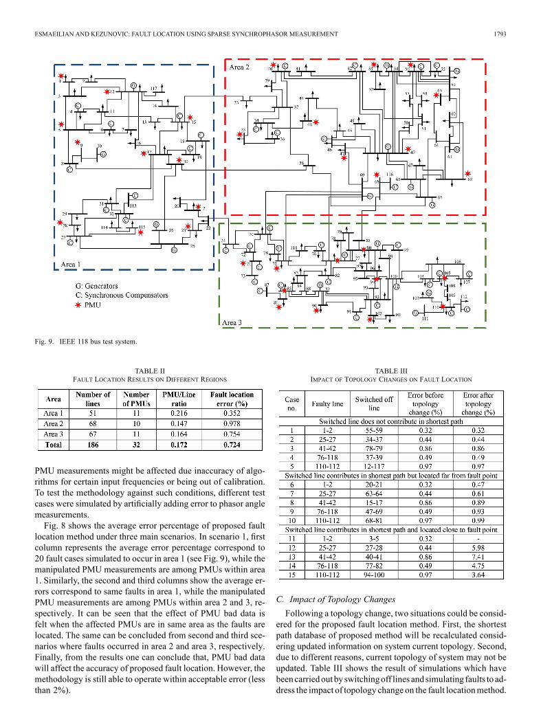
Fig. 9. IEEE 118 bus test system.
TABLE IIFAULT LOCATION RESULTS ON DIFFERENT REGIONS
PMU measurements might be affected due inaccuracy of algo-rithms for certain input frequencies or being out of calibration.To test the methodology against such conditions, different testcases were simulated by artificially adding error to phasor anglemeasurements.Fig. 8 shows the average error percentage of proposed fault
location method under three main scenarios. In scenario 1, firstcolumn represents the average error percentage correspond to20 fault cases simulated to occur in area 1 (see Fig. 9), while themanipulated PMU measurements are among PMUs within area1. Similarly, the second and third columns show the average er-rors correspond to same faults in area 1, while the manipulatedPMU measurements are among PMUs within area 2 and 3, re-spectively. It can be seen that the effect of PMU bad data isfelt when the affected PMUs are in same area as the faults arelocated. The same can be concluded from second and third sce-narios where faults occurred in area 2 and area 3, respectively.Finally, from the results one can conclude that, PMU bad datawill affect the accuracy of proposed fault location. However, themethodology is still able to operate within acceptable error (lessthan 2%).
TABLE IIIIMPACT OF TOPOLOGY CHANGES ON FAULT LOCATION
C. Impact of Topology ChangesFollowing a topology change, two situations could be consid-
ered for the proposed fault location method. First, the shortestpath database of proposed method will be recalculated consid-ering updated information on system current topology. Second,due to different reasons, current topology of system may not beupdated. Table III shows the result of simulations which havebeencarriedout by switchingoff lines andsimulating faults to ad-dress the impact of topology change on the fault locationmethod.

1794 IEEE TRANSACTIONS ON POWER DELIVERY, VOL. 31, NO. 4, AUGUST 2016
The simulation results illustrate that fault location methodwould be affected only in certain cases where the switched offline is contributing in shortest path of electromechanical-wavepropagation from fault to buses with PMUs. However, the faultlocation error is acceptable if the switched line is far from thefaulty line.Aswedescribed in previous subsection, PMUswhichare far from faulty line cannot dramatically affect output of theproposed method. Furthermore, to detect a topology change, apre-defined signal (ping) could be generated at one of the PMUequipped buses and ToAs are measured at other PMU locations.If there is any difference between one of the measured ToAsand corresponding calculated ToAs, a topology change acrossthe shortest path among corresponding two buses is determined.
D. Impact of Availability of PMUsThe other concern associated with wide area measurements
based applications is unavailability of PMUs due to various rea-sons such as communication failure, device failure, etc. In suchcases, applications must be robust enough to tolerate unavail-ability of measurements from one or more PMUs.Fig. 10 depicts the average error percentage of fault location
algorithm versus total number of PMUs assumed to be out ofservice. After taking each PMU out of service, 20 faults aresimulated and average error percentage is used to plot Fig. 10.Similar to previous subsection, three main scenarios were sim-ulated considering three areas in Fig. 9. In Fig. 10(a), faults aresimulated in area 1, while dash, dash-dot and dotted lines arerelated to the cases where out of service PMUs are within areas1, 2 and 3, respectively. As can be seen, the average error is lessthan 2% (dash line) even after removing first 6 PMUs from area1. It can be concluded that even under availability of 5 PMUsin area 1, the method operates with acceptable accuracy. Theerror remains under 2% even after removing all PMUs in areas2 and 3, respectively. The same observation could be obtainedby looking into Figs. 10(b) and (c). It can be concluded that faultlocation method on each of the three areas is robust to unavail-ability of PMUs in other two areas. Since optimal fault locationresults may be sensitive to placement of PMUs and location offault occurrence, one can conclude that the proposedmethod canoperate within acceptable error % with quite less numberof PMUs than what is needed to satisfy the observability re-quirement suggested by an optimal PMU placement reportedin [36].The last scenario is designed to consider the impact of com-
bination of topology changes and PMU availability on the ac-curacy of fault location method. Table IV shows the result offault location method by inserting faults at three different lineswhile two lines and two PMUs are taken out. In cases 1 and2, faults occurred on line 1-2 (area 1) while lines (55-59 and24-70) are taken out but are not contributing to the shortest pathto PMUs. In case 1 where the two out of service PMUs (49, 71)are not located in the same area as fault, the fault location errorremains the same. In case 2 where the two out of service PMUs(49, 71) are located in the same area as fault, the fault locationerror slightly increases from 0.32% to 0.41%. In cases 7 and8, all simulation parameters are the same except switched lineswhich are selected from those that contribute to the shortest pathbut located far from the fault point. Similarly, in cases 13 and
Fig. 10. Effect of unavailability of PMUs on fault location accuracy.
TABLE IVIMPACT OF COMBINATION OF TOPOLOGY CHANGES AND PMU AVAILABILITY

ESMAEILIAN AND KEZUNOVIC: FAULT LOCATION USING SPARSE SYNCHROPHASOR MEASUREMENT 1795
14, all simulation parameters are the same except the switchedlines are selected from those that contribute to shortest path andare located close to the fault point. From Table IV, it can be con-cluded that the fault location accuracy would not be affected ifPMUs or lines out of service are away from the fault point. Theerrors would be tolerable even if the out of service PMUs andlines are in the same area where the fault has occurred.
V. CONCLUSIONIn this paper a unique fault location methodology based on
propagation of electromechanical-wave oscillation in powersystem is proposed. The main advantages of the proposedmethodology over previously established methods are asfollows.• Unlike different wide area measurement based methodswhich require information from all buses, the proposedmethod uses measurements from sparsely located PMUswhich reduce cost of implementation.
• The calculation burden is less than most of single- ormultiple-end fault location methods, since the pre-cal-culated shortest path database using Dijkstra's algorithmwill remain vailed until the topology of the power systemchanges.
• The proposed method could be implemented with PMUsor any other IED devices located in that substation, whichcan measure and report GPS synchronized phasors.
• The methodology can operate with acceptable accuracyunder impacts of topology changes, PMUs bad data or un-availability of one or more PMU measurements, whichdemonstrate the algorithm is effective even under avail-ability of sparse measurements.
REFERENCES[1] Z. Galijasevic and A. Abur, “Fault location using voltage measure-
ments,” IEEE Trans. Power Del., vol. 17, no. 2, pp. 441–445, Apr.2002.
[2] M. S. Sachdev and M. A. Baribeau, “A new algorithm for digitalimpedance relays,” IEEE Trans. Power App. Syst., vol. PAS-98, no. 6,pp. 2232–2239, Dec. 1979.
[3] A. A. Girgis, “A new Kalman filtering based digital distance relay,”IEEE Trans. Power App. Syst., vol. PAS-101, no. 9, pp. 3471–3480,Sep. 1982.
[4] T. Kawady and J. Stenzel, “A practical fault location approach fordouble circuit transmission lines using single end data,” IEEE Trans.Power Del., vol. 18, no. 4, pp. 1166–1173, Oct. 2003.
[5] H. Ha, B. H. Zhang, and Z. L. Lv, “A novel principle of single-endedfault location technique for EHV transmission lines,” IEEE Trans.Power Del., vol. 18, no. 4, pp. 1147–1151, Oct. 2003.
[6] C. E. M. Pereira and L. C. Zanetta, “Fault location in transmission linesusing one-terminal post-fault voltage data,” IEEE Trans. Power Del.,vol. 19, no. 2, pp. 570–575, Apr. 2004.
[7] Z. Qingchao et al., “Fault location of two-parallel transmission line fornon-earth fault using one-terminal data,” IEEE Trans. Power Del., vol.14, no. 3, pp. 863–867, Jul. 1999.
[8] M. Farshad and J. Sadeh, “Accurate single-phase fault-locationmethod for transmission lines based on k-nearest neighbor algorithmusing one-end voltage,” IEEE Trans. Power Del., vol. 27, no. 4, pp.2360–2367, Oct. 2012.
[9] Y. Liao and S. Elangovan, “Unsynchronized two-terminal transmis-sion-line fault-location without using line parameters,” Proc. Inst.Elect. Eng., Gen. Transm. Distrib., vol. 153, no. 6, pp. 639–643, Nov.2006.
[10] J. Izykowski et al., “Accurate noniterative fault location algorithm uti-lizing two-end unsynchronized measurements,” IEEE Trans. PowerDel., vol. 25, no. 1, pp. 72–80, Jan. 2010.
[11] E. G. Silveira and C. Pereira, “Transmission line fault location usingtwo-terminal data without time synchronization,” IEEE Trans. PowerDel., vol. 22, no. 1, pp. 498–499, Feb. 2007.
[12] M. Davoudi, J. Sadeh, and E. Kamyab, “Parameter-free fault locationfor transmission lines based on optimization,” IET Gen., Transm. Dis-trib., vol. 9, no. 11, pp. 1061–1068, Aug. 2015.
[13] M. Davoudi, J. Sadeh, and E. Kamyab, “Time domain fault locationon transmission lines using genetic algorithm,” in Proc. 11th Int. Conf.Environment Elect. Eng., May 2012, pp. 1087–1092.
[14] M. Kezunovic and B. Perunicic, “Automated transmission line faultanalysis using synchronized sampling at two ends,” IEEE Trans. PowerSyst., vol. 11, no. 1, pp. 441–447, Feb. 1996.
[15] A. Gopalakrishnan et al., “Fault location using the distributed param-eter transmission line model,” IEEE Trans. Power Del., vol. 15, no. 4,pp. 1169–1174, Oct. 2000.
[16] P. Dutta, A. Esmaeilian, and M. Kezunovic, “Transmission-line faultanalysis using synchronized sampling,” IEEE Trans. Power Del., vol.29, no. 2, pp. 942–950, Apr. 2014.
[17] J. A. Jiang et al., “An adaptive PMU based fault detection/locationtechnique for transmission lines part I: Theory and algorithms,” IEEETrans. Power Del., vol. 15, no. 2, pp. 486–493, Apr. 2000.
[18] J. A. Jiang et al., “An adaptive PMU based fault detection/locationtechnique for transmission lines. II. PMU implementation and per-formance evaluation,” IEEE Trans. Power Del., vol. 15, no. 4, pp.1136–1146, Oct. 2000.
[19] Y. H. Lin et al., “A new PMU-based fault detection/location techniquefor transmission lines with consideration of arcing fault discrimina-tion—Part I: Theory and algorithms,” IEEE Trans. Power Del., vol.19, no. 4, pp. 1587–1593, Oct. 2004.
[20] Y. H. Lin et al., “A new PMU-based fault detection/location techniquefor transmission lines with consideration of arcing fault discrimina-tion—Part I: Theory and algorithms,” IEEE Trans. Power Del., vol.19, no. 4, pp. 1594–1601, Oct. 2004.
[21] Y. Liao, “Fault location for single-circuit line based on bus-impedancematrix utilizing voltage measurements,” IEEE Trans. Power Del., vol.23, no. 2, pp. 609–617, Apr. 2008.
[22] M. Korkali, H. Lev-Ari, and A. Abur, “Traveling-wave-based faultlocation technique for transmission grids via wide-area synchronizedvoltage measurements,” IEEE Trans. Power Syst., vol. 27, no. 2, pp.1003–1011, May 2012.
[23] M. Korkali and A. Abur, “Optimal deployment of wide-area synchro-nized measurements for fault-location observability,” IEEE Trans.Power Syst., vol. 28, no. 1, pp. 482–489, Feb. 2013.
[24] Y. Chen, D. Liu, and B. Xu, “Wide-area traveling wave fault locationsystem based on IEC61850,” IEEE Trans. Smart Grid, vol. 4, no. 2, pp.1207–1215, Jun. 2013.
[25] S. Azizi et al., “A traveling-wave-based methodology for wide-areafault location in multi-terminal DC systems,” IEEE Trans. Power Del.,vol. 14, no. 3, pp. 863–867, Jul. 1999.
[26] J. S. Thorp et al., “Electromechanical wave propagation in large elec-tric power systems,” IEEE Trans. Circuits Syst. I, Fundam. TheoryAppl., vol. 45, no. 6, pp. 614–622, Jun. 1998.
[27] A. Semlyen, “Analysis of disturbance propagation in power systemsbased on a homogeneous dynamic model,” IEEE Trans. Power App.Syst., vol. PAS-93, no. 2, pp. 676–684, Mar. 1974.
[28] P. Dersin and A. Levis, “Feasibility sets for steady-state loads in elec-tric power networks,” IEEE Trans. Power App. Syst., vol. PAS-101, no.1, pp. 60–70, Jan. 1982.
[29] A. J. Arana, “Analysis of electromechanical phenomena in thepower-angle domain,” Ph.D. dissertation, Elect. Eng. Dept., VirginiaPolytechnic Institute and State University, Blacksburg, VA, USA,Dec. 2009.
[30] M. Parashar et al., “Continuum modeling of electromechanical dy-namics in large-scale power systems,” IEEE Trans. Circuits Syst. I,Reg. Papers, vol. 51, no. 9, pp. 1848–1858, Sep. 2004.
[31] E. W. Dijkstra, “A note on two problems in connexion with graphs,”Numer. Math., vol. 1, pp. 269–271, 1959.
[32] D. K. Ranaweera, “Comparison of neural network models for faultdiagnosis of power systems,” Elect. Power Syst. Res., vol. 29, pp.99–104, 1994.
[33] A. Abdullah et al., “Test bed for cascading failure scenarios evalua-tion,” presented at the IPST 2013, Vancouver, BC, Canada, Jul. 2013.
[34] N. Abramson, Information Theory and Coding. New York, USA:McGraw-Hill, 1983.

1796 IEEE TRANSACTIONS ON POWER DELIVERY, VOL. 31, NO. 4, AUGUST 2016
[35] R. Christie, Power system test archive, Aug. 1999. [Online]. Available:http://www.ee.washington.edu/research/pstca
[36] S. Azizi, A. Dobakhshari, A. N. Sarmadi, and A. M. Ranjbar, “Op-timal PMU placement by an equivalent linear formulation for exhaus-tive search,” IEEE Trans. Smart Grid, vol. 3, no. 1, pp. 174–182, Mar.2012.
Ahad Esmaeilian (S'08) was born in Iran in 1987.He received the B.Sc. and M.Sc. degrees in powersystem engineering from the University of Tehran,Tehran, Iran, in 2009 and 2012, respectively.Currently, he is a Graduate Student with Texas
A&M University, College Station, TX, USA. Hismain research interests are power system protection,fault location, and application of intelligent methodsto power system monitoring and protection.
M. Kezunovic (S'77–M'80–SM'85–F'99) receivedthe Dipl. Ing. degree in electrical engineering fromthe University of Sarajevo, Sarajevo, Bosnia andHerzegovina, in 1974 and the M.S. and Ph.D.degrees in electrical engineering from the Universityof Kansas, Lawrence, KS, USA, in 1977 and 1980,respectively.He is the Eugene E. Webb Professor and Site
Director of Power Engineering Research Center(PSerc), an NSF I/UCRC at Texas A&M University,College Station, TX, USA. He is also the Director
of the Smart Grid Center. He has published more than 450 papers, given over100 seminars, invited lectures and short courses, and consulted for over 50companies worldwide. He is the Principal of XpertPower Associates, TX,USA, a consulting firm specializing in automated fault analysis and intelligentelectronic device testing. His main research interests are digital simulators andsimulation methods for relay testing, as well as the application of intelligentmethods to power system monitoring, control, and protection.Dr. Kezunovic is a Fellow of CIGRE and a Registered Professional Engineer
in Texas.