ieee+387 1995+(diesel+generator)
TRANSCRIPT
The Institute of Electrical and Electronics Engineers, Inc.345 East 47th Street, New York, NY 10017-2394, USA
Copyright © 1996 by the Institute of Electrical and Electronics Engineers, Inc.All rights reserved. Published 1996. Printed in the United States of America.
ISBN 1-55937-581-7
No part of this publication may be reproduced in any form, in an electronic retrieval system or otherwise, without the prior written permission of the publisher.
IEEE Std 387-1995(Revision of IEEE Std 387-1984)
IEEE Standard Criteria for Diesel-Generator Units Applied as Standby Power Supplies for Nuclear Power Generating Stations
Sponsor
Nuclear Power Engineering Committeeof theIEEE Power Engineering Society
Approved December 12, 1995
IEEE Standards Board
Abstract: The criteria for the application and testing of diesel-generator units as Class 1E standbypower supplies in nuclear power generating stations is described.Keywords: aging classification, auxiliary equipment, capability, controls, design criteria, designfeatures, diesel-generator units, documentation requirements, engine, generator, load profile,modifications, operation, periodic testing, pre-operational testing, production testing, protection,qualification requirements, rating, records, reliability program, scope, seismic qualification, site test-ing, standby power supply, testing requirements, test parameters, type testing

IEEE Standards
documents are developed within the Technical Committees of the IEEE Societiesand the Standards Coordinating Committees of the IEEE Standards Board. Members of the com-mittees serve voluntarily and without compensation. They are not necessarily members of the Insti-tute. The standards developed within IEEE represent a consensus of the broad expertise on thesubject within the Institute as well as those activities outside of IEEE that have expressed an inter-est in participating in the development of the standard.
Use of an IEEE Standard is wholly voluntary. The existence of an IEEE Standard does not implythat there are no other ways to produce, test, measure, purchase, market, or provide other goods andservices related to the scope of the IEEE Standard. Furthermore, the viewpoint expressed at thetime a standard is approved and issued is subject to change brought about through developments inthe state of the art and comments received from users of the standard. Every IEEE Standard is sub-jected to review at least every five years for revision or reaffirmation. When a document is morethan five years old and has not been reaffirmed, it is reasonable to conclude that its contents,although still of some value, do not wholly reflect the present state of the art. Users are cautioned tocheck to determine that they have the latest edition of any IEEE Standard.
Comments for revision of IEEE Standards are welcome from any interested party, regardless ofmembership affiliation with IEEE. Suggestions for changes in documents should be in the form of aproposed change of text, together with appropriate supporting comments.
Interpretations: Occasionally questions may arise regarding the meaning of portions of standards asthey relate to specific applications. When the need for interpretations is brought to the attention ofIEEE, the Institute will initiate action to prepare appropriate responses. Since IEEE Standards rep-resent a consensus of all concerned interests, it is important to ensure that any interpretation hasalso received the concurrence of a balance of interests. For this reason IEEE and the members of itstechnical committees are not able to provide an instant response to interpretation requests except inthose cases where the matter has previously received formal consideration.
Comments on standards and requests for interpretations should be addressed to:
Secretary, IEEE Standards Board445 Hoes LaneP.O. Box 1331Piscataway, NJ 08855-1331USA
Authorization to photocopy portions of any individual standard for internal or personal use isgranted by the Institute of Electrical and Electronics Engineers, Inc., provided that the appropriatefee is paid to Copyright Clearance Center. To arrange for payment of licensing fee, please contactCopyright Clearance Center, Customer Service, 222 Rosewood Drive, Danvers, MA 01923 USA;(508) 750-8400. Permission to photocopy portions of any individual standard for educational class-room use can also be obtained through the Copyright Clearance Center.
Note: Attention is called to the possibility that implementation of this standard mayrequire use of subject matter covered by patent rights. By publication of this standard,no position is taken with respect to the existence or validity of any patent rights inconnection therewith. The IEEE shall not be responsible for identifying all patents forwhich a license may be required by an IEEE standard or for conducting inquiries intothe legal validity or scope of those patents that are brought to its attention.

Introduction
(This introduction is not part of IEEE Std 387-1995, IEEE Standard Criteria for Diesel-Generator Units Applied asStandby Power Supplies for Nuclear Power Generating Stations.)
This standard supplements IEEE Std 308-1991, IEEE Standard Criteria for Class 1E Power Systems forNuclear Power Generating Stations, in that it amplifies subclause 6.2.4 of that standard (Standby powersupplies) concerning requirements for diesel-generator units.
The IEEE has developed this standard to provide the principal design criteria, design features, qualificationconsiderations, and testing requirements for individual diesel-generator units, including auxiliary equipmentand controls within the scope of this standard used in the standby power supply of a nuclear facility, whichcomply with the Nuclear Regulatory Commission’s Code of Federal Regulations (10 CFR 50).
This standard presents specific procedures and criteria applicable to qualifying the diesel-generator unit andsupplements the criteria described in IEEE Std 323-1983, IEEE Standard for Qualifying Class 1EEquipment for Nuclear Power Generating Stations, and IEEE Std 627-1980, IEEE Standard for DesignQualification of Safety System Equipment Used in Nuclear Power Generating Stations.
This revision of the standard provides additional detail in the following areas:
a) Defining specific qualification requirements
b) Clarifying scope and scope diagram
c) Providing requirements for no-load and light-load operation, since extended operation under theseconditions may be detrimental to unit performance
d) Expanding factory production testing and site testing criteria
e) Updating specific surveillance requirements
f) Providing guidance for test parameters (annex C)
g) Providing guidance for reliability program elements (annex D)
This revision of the standard incorporates periodic testing requirements described in IEEE Std 749-1983,IEEE Standard for Periodic Testing of Diesel-Generator Units Applied as Standby Power Supplies inNuclear Power Generating Stations, which has been withdrawn.
Industry practice is focusing toward monitoring and trending to facilitate aging and reliabilitydeterminations. This standard provides guidance for recommended test parameters and reliability programelements as described in annexes C and D. These guidelines reflect industry practices and are in agreementwith guidelines developed by the Nuclear Management and Resources Council (NUMARC), now known asthe Nuclear Energy Institute (NEI).
The qualification requirements delineated in this standard consider aging considerations as potentialcommon mode failure mechanisms. Operating experience is generally available on diesel-generator unitssimilar to those covered by this standard, and is useful in establishing the effect of aging mechanisms forthose components where the technical state-of-the-art does not allow for techniques such as acceleratedaging. The basis for allowing operating experience is supplemented by noting that the application of thesediesel-generator units for nuclear service is such that the actual operating time under loaded conditions isexpected to be less than one year continuous service in the 40-year life expectancy of the plant. For areaswhere the state-of-the-art is not as limited, accelerated aging techniques should be used.
Components or assemblies that have been used for testing should not be placed into in-service use unlessthey have been analyzed to demonstrate their adequacy for in-service use.
iii

Other industry standards exist or are being developed to cover topics related to this standard, including theAmerican Nuclear Society series standardsa describing design requirements for diesel-generator unitauxiliary systems.
Adherence to these criteria may not suffice for ensuring public health and safety because it is the integratedperformance of the structures, the fluid systems, the instrumentation systems, and the electrical systems ofthe station that establishes the consequences of accidents. Each applicant has the responsibility to ensure thatthis integrated performance is adequate.
This standard was prepared by Working Group 4.2 of the Auxiliary Power Subcommittee (SC-4) of theNuclear Power Engineering Committee of the IEEE Power Engineering Society. At the time this standardwas approved, the working group had the following membership:
E. I. Fabri, ChairP. R. Johnson, Secretary
The following persons were involved in the preparation of the standard, but were not working groupmembers at the time of approval.
The Auxiliary Power Subcommittee (SC-4) of the Nuclear Power Engineering Committee had the followingmembership at the time this revision was approved:
R. Weronick, Chair P. B. Stevens, Vice ChairJ. P. Carter, Secretary
aThese publications are available from the American Nuclear Society, 555 North Kensington Avenue, LaGrange Park, IL 60525, USA.
L. F. BednarT. N. ChanO. P. ChopraL. Fusegni
D. D. GaleazziL. G. HajosK. R. Hoopingarner
J. HorneF. KauffmannD. SandiforthN. A. Traeger
J. J. Burns W. Farmer
R. E. AllenG. AttarianF. D. BaxterW. J. BoyerJ. ChiloyanE. I. FabriA. S. GillL. C. GonzalezD. T. GoodneyP. K. Guha
P. R. JohnsonJ. D. KueckH. C. LeakeJ. D. MacDonaldG. MorrisB. NemroffG. L. NicelyR. D. F. ParkerC. A. Petrizzo
D. J. RanftH. A. RobinsonA. R. RobyG. J. SadauskasT. R. SimsB. J. SkorasD. SmithJ. E. Stoner, Jr.R. L. SwallowsP. Szabados
iv

The following persons (members of the Nuclear Power Engineering Committee) were on the ballotingcommittee:
When the IEEE Standards Board approved this standard on December 12, 1995, it had the followingmembership:
E. G. “Al” Kiener, Chair Donald C. Loughry, Vice ChairAndrew G. Salem, Secretary
*Member Emeritus
Also included are the following nonvoting IEEE Standards Board liaisons:
Satish K. AggarwalRobert E. HebnerSteve SharkeyChester C. Taylor
Valerie E. ZelentyIEEE Standards Project Editor
Satish K. AggarwalRussell E. AllenVincent BacanskasJohn T. BauerFarouk D. BaxterWes W. BowersDan F. BrosnanNissen M. BursteinAris S. CandrisS. P. CarfagnoRobert C. CarruthRobert L. CopyakGary L. DomanEdward F. Dowling
Arthur R. DuCharmeRich E. DulskiJay ForsterJohn M. GallagherWil C. GangloffLouis W. GaussaLuis C. GonzalezLawrence P. GradinBritton P. GrimRobert E. HallGregory K. HenrySonny KasturiJames T. KeiperJ. Donald LamontAlex Marion
R. B. MillerRichard E. MillerBurt NemroffMohandas PaiJoseph R. PenlandNewell S. PorterEd W. RhoadsArnold RobyNeil P. SmithPeter B. StevensPeter SzabadosJames E. ThomasJohn T. UlloMark S. Zar
Gilles A. BarilClyde R. CampJoseph A. CannatelliStephen L. DiamondHarold E. EpsteinDonald C. FleckensteinJay Forster*Donald N. HeirmanRichard J. Holleman
Jim IsaakBen C. JohnsonSonny KasturiLorraine C. KevraIvor N. KnightJoseph L. Koepfinger*D. N. “Jim” LogothetisL. Bruce McClung
Marco W. MigliaroMary Lou PadgettJohn W. PopeArthur K. ReillyGary S. RobinsonIngo RüschChee Kiow TanLeonard L. TrippHoward L. Wolfman
v

vi
Contents
CLAUSE PAGE
1. Overview.............................................................................................................................................. 1
1.1 Scope............................................................................................................................................ 11.2 Purpose......................................................................................................................................... 4
2. References............................................................................................................................................ 4
3. Definitions............................................................................................................................................ 5
4. Principal design criteria ....................................................................................................................... 6
4.1 Capability..................................................................................................................................... 64.2 Ratings ......................................................................................................................................... 74.3 Interactions................................................................................................................................... 74.4 Design and application considerations......................................................................................... 74.5 Design features............................................................................................................................. 9
5. Factory production testing ................................................................................................................. 11
5.1 General....................................................................................................................................... 115.2 Factory production tests............................................................................................................. 12
6. Qualification requirements................................................................................................................. 13
6.1 General....................................................................................................................................... 136.2 Initial type tests .......................................................................................................................... 136.3 Aging.......................................................................................................................................... 156.4 Seismic qualification requirements............................................................................................ 176.5 Ongoing surveillance ................................................................................................................. 176.6 Modifications ............................................................................................................................. 186.7 Documentation........................................................................................................................... 18
7. Site testing.......................................................................................................................................... 18
7.1 Testing........................................................................................................................................ 187.2 Site acceptance testing ............................................................................................................... 187.3 Pre-operational testing ............................................................................................................... 207.4 Periodic testing........................................................................................................................... 217.5 Test descriptions ........................................................................................................................ 237.6 Records ...................................................................................................................................... 25
ANNEX
Annex A (informative) Method for establishing a load profile for a diesel-generator unit ........................ 27
Annex B (informative) Example of aging and aged equipment testing...................................................... 29
Annex C (informative) Recommended diesel-generator unit monitoring and trending parameters........... 35
Annex D (informative) Diesel-generator unit reliability program elements ............................................... 39

IEEE Standard Criteria for Diesel-Generator Units Applied as Standby Power Supplies for Nuclear Power Generating Stations
1. Overview
1.1 Scope
This standard describes the criteria for the application and testing of diesel-generator units as Class 1Estandby power supplies in nuclear power generating stations.
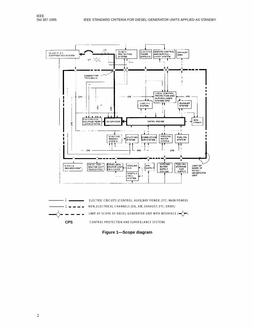
Figure 1 shows the boundaries of systems and equipment included in the scope of this standard. Site testingis covered in clause 7, and the boundaries for site testing are given in 1.1.2.
1.1.1 Inclusions
The following items are within the scope of this standard:
a) The diesel engine, including
1) The flywheel and coupling (if applicable)
2) The combustion air system, starting at the engine air intake connection, including the effects ofany remote air intake filter or silencer, or both
3) The starting system
4) The starting energy system
5) The fuel oil system, including the day tank and the filters and strainers between the day tankand the engine
6) The lubricating oil system
7) The cooling system, starting at the point where the cooling medium is introduced to the diesel-generator unit
8) The exhaust system, including the exhaust silencer, but excluding piping from the engineexhaust connection to the inlet of the silencer and silencer tail pipe
9) The governor system
1
IEEEStd 387-1995 IEEE STANDARD CRITERIA FOR DIESEL-GENERATOR UNITS APPLIED AS STANDBY
Figure 1—Scope diagram
;
;
CPS
ELECTRIC CIRCUITS (CONTROL, AUXILIARY POWER, ETC; MAIN POWER)
NON_ELECTRICAL CHANNELS (OIL, AIR, EXHAUST, ETC; DRIVE)
LIMIT OF SCOPE OF DIESEL-GENERATOR UNIT WITH INTERFACE ( )
CONTROL PROTECTION AND SURVEILLANCE SYSTEMS
2
IEEEPOWER SUPPLIES FOR NUCLEAR POWER GENERATING STATIONS Std 387-1995
b) The generator, including
1) The main leads terminating at the generator terminals2) The excitation and voltage regulation systems
c) The local control, protection, and surveillance systems associated with the diesel engine, thegenerator, and their auxiliary equipment and systems cited above
d) The ac and dc distribution systems associated with the diesel engine, the generator, and theirauxiliary equipment and systems cited above, exclusive of the auxiliary power system beyond thegenerator terminals
e) Those elements that are essential to the safety function of diesel-generator units within the scope ofthis standard (see figure 1)
f) Evaluation of the characteristics of the service environment relative to performance and qualification
1.1.2 Inclusions for site testing
The following items are included for site testing purposes only, as described in clause 7.
a) The ac and dc power distribution system, which includes
1) Circuits for conveying ac power from the diesel-generator
terminals up to and including themain disconnect device
2) Circuits for conveying ac or dc power to the diesel-generator units and associated controls
3) DC power supplies, if dedicated to the diesel-generator unit
b) The remote and local control, protection, and surveillance systems, which include
1) Devices for automatic and manual starting2) Devices for load shedding and sequencing3) Remote devices for the protection of the diesel-generator unit and its auxiliary equipment4) Synchronizing equipment5) Field flashing devices
1.1.3 Exclusions
The following items are outside of the scope of this standard:
a) Diesel-generator unit enclosure and foundations
b) External service equipment and systems that are a part of, or that are housed in, the diesel-generatorunit enclosure, other than those tabulated in 1.1.1, such as equipment for providing and conveyingcombustion air, ventilating air, etc., to the vicinity of the diesel-generator unit
c) Fuel oil storage system (day tank, storage tank, transfer pumps and filters, and strainers between thestorage tank and the day tank)
d) The control, protection, and surveillance systems for
1) Protecting the loads energized by the diesel-generator unit
2) Prevention of common-mode failure between the preferred power supply and the standbypower supply
e) Determination of the characteristics of the service environment
f) Fire protection system
3
IEEEStd 387-1995 IEEE STANDARD CRITERIA FOR DIESEL-GENERATOR UNITS APPLIED AS STANDBY
1.2 Purpose
The purpose of this standard is to provide the principal design criteria, the design features, testing, andqualification requirements for the individual diesel-generator units that enable them to meet their functionalrequirements as a part of the standby power supply under the conditions produced by the design basis eventscataloged in the Plant Safety Analysis.
2. References
This standard shall be used in conjunction with the following standards.
ANS 59.51-1989, Fuel Oil Systems for Emergency Diesel Generators.
1
ANSI C50.10-1977, American National Standard General Requirements for Synchronous Machines.
2
ANSI/ASME 1995 Boiler and Pressure Vessel Code.
3
ANSI/NFPA 37-1994, Stationary Combustion Engines and Gas Turbines.
IEEE Std 100-1992, The New IEEE Standard Dictionary of Electrical and Electronics Terms (ANSI).
4
IEEE Std 308-1991, IEEE Standard Criteria for Class 1E Power Systems for Nuclear Power GeneratingStations (ANSI).
IEEE Std 323-1983 (Reaff 1990), IEEE Standard for Qualifying Class 1E Equipment for Nuclear PowerGenerating Stations (ANSI).
IEEE Std 338-1987 (Reaff 1993), IEEE Standard Criteria for the Periodic Surveillance Testing of NuclearPower Generating Station Safety Systems (ANSI).
IEEE Std 344-1987 (Reaff 1993), IEEE Recommended Practice for Seismic Qualification of Class 1EEquipment for Nuclear Power Generating Stations (ANSI).
IEEE Std 384-1992, IEEE Standard Criteria for Independence of Class 1E Equipment and Circuits (ANSI).
IEEE Std 603-1991, IEEE Standard Criteria for Safety Systems for Nuclear Power Generating Stations(ANSI).
IEEE Std 627-1980 (Reaff 1991), IEEE Standard for Design Qualification of Safety Equipment Used inNuclear Power Generating Stations (ANSI).
IEEE Std 741-1990, IEEE Standard Criteria for the Protection of Class 1E Power Systems and Equipment inNuclear Power Generating Stations (ANSI).
NEMA MG 1-1993, Motors and Generators.
5
1
ANS publications are available from the American Nuclear Society, 555 North Kensington Avenue, La Grange Park, IL 60525, USA.
2
ANSI publications are available from the Sales Department, American National Standards Institute, 11 West 42nd Street, 13th Floor,New York, NY 10036, USA.
3
This publication is available from the American Society of Mechanical Engineers, 22 Law Drive, Fairfield, NJ 07007, USA.
4
IEEE publications are available from the Institute of Electrical and Electronics Engineers, 445 Hoes Lane, P.O. Box 1331, Piscataway,NJ 08855-1331, USA.
5
NEMA publications are available from the National Electrical Manufacturers Association, 2101 L Street NW, Suite 300, Washington,DC 20037, USA.
4
IEEEPOWER SUPPLIES FOR NUCLEAR POWER GENERATING STATIONS Std 387-1995
3. Definitions
3.1 acceptable: Demonstrated to be adequate by the safety analysis of the plant.
3.2 continuous rating (of diesel-generator unit): The electric power output capability that the diesel-generator unit can maintain in the service environment for 8760 h of operation per year with only scheduledoutages for maintenance.
3.3 design basis events: Postulated events used in the design to establish the performance requirements ofthe structures and systems.
3.4 design load: That combination of electric loads (kW and kvar), having the most severe power demandcharacteristic, which is provided with electric energy from a diesel-generator unit for the operation ofengineered safety features and other systems required during and following shutdown of the reactor.
3.5 diesel-generator unit: An independent source of standby electrical power that consists of a diesel-fueledinternal combustion engine (or engines) coupled directly to an electrical generator (or generators); the asso-ciated mechanical and electrical auxiliary systems; and the control, protection, and surveillance systems.
3.6 engine equilibrium temperature: The condition at which the jacket water and lube oil temperatures areboth within ± 5.5 °C (10 °F) of their normal operating temperatures established by the engine manufacturer.
3.7 load profile: The magnitude and duration of loads (kW and kvar) applied in a prescribed time sequence,including the transient and steady-state characteristics of the individual loads.
3.8 qualified diesel-generator unit: A diesel-generator unit that meets the qualification requirements of thisstandard.
3.9 redundant equipment or system: An equipment or system that duplicates the essential function ofanother equipment or system to the extent that either may perform the required function regardless of thestate of operation or failure of the other.
3.10 service environment: The aggregate of conditions surrounding the diesel-generator unit in itsenclosure, while serving the design load during normal, accident, and post-accident operation.
3.11 short-time rating (of diesel-generator unit): The electric power output capability that the diesel-generator unit can maintain in the service environment for 2 h in any 24 h period, without exceeding themanufacturer’s design limits and without reducing the maintenance interval established for the continuousrating.
NOTE—Operation at this higher rating does not limit the use of the diesel-generator unit at its continuous rating.
3.12 standby power supply: The power supply that is selected to furnish electric energy when the preferredpower supply is not available.
3.13 start-diesel signal: That input signal to the diesel-generator unit start logic that initiates a diesel-generator unit start sequence.
3.14 surveillance: The determination of the state or condition of a system or subsystem.
5
IEEEStd 387-1995 IEEE STANDARD CRITERIA FOR DIESEL-GENERATOR UNITS APPLIED AS STANDBY
4. Principal design criteria
4.1 Capability
4.1.1 General
When in service, each diesel-generator unit shall have the capability of performing as a redundant unit of astandby power supply, in accordance with the requirements stated in IEEE Std 308-1991.6
4.1.2 Mechanical and electrical capabilities
The diesel-generator unit shall also have each of the following specific capabilities to meet the design,application, and qualification requirements of this standard:
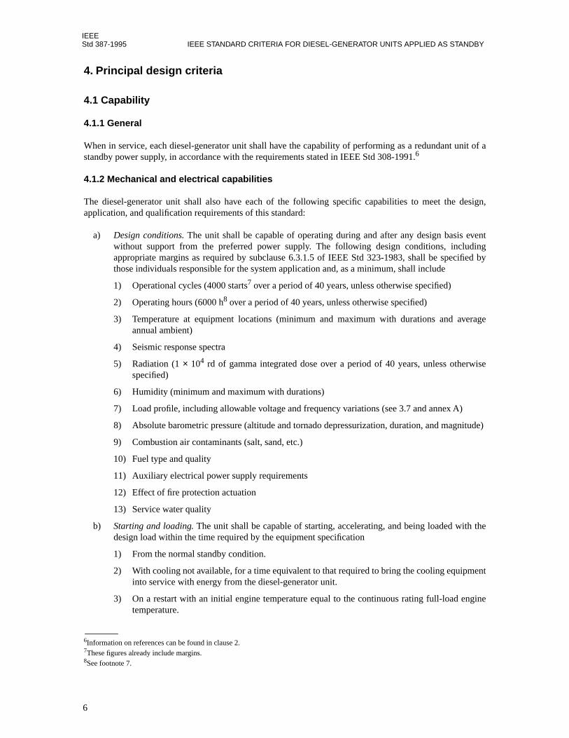
a) Design conditions. The unit shall be capable of operating during and after any design basis eventwithout support from the preferred power supply. The following design conditions, includingappropriate margins as required by subclause 6.3.1.5 of IEEE Std 323-1983, shall be specified bythose individuals responsible for the system application and, as a minimum, shall include
1) Operational cycles (4000 starts7 over a period of 40 years, unless otherwise specified)
2) Operating hours (6000 h8 over a period of 40 years, unless otherwise specified)
3) Temperature at equipment locations (minimum and maximum with durations and averageannual ambient)
4) Seismic response spectra
5) Radiation (1 × 10⁴ rd of gamma integrated dose over a period of 40 years, unless otherwisespecified)
6) Humidity (minimum and maximum with durations)
7) Load profile, including allowable voltage and frequency variations (see 3.7 and annex A)
8) Absolute barometric pressure (altitude and tornado depressurization, duration, and magnitude)
9) Combustion air contaminants (salt, sand, etc.)
10) Fuel type and quality
11) Auxiliary electrical power supply requirements
12) Effect of fire protection actuation
13) Service water quality
b) Starting and loading. The unit shall be capable of starting, accelerating, and being loaded with thedesign load within the time required by the equipment specification
1) From the normal standby condition.
2) With cooling not available, for a time equivalent to that required to bring the cooling equipmentinto service with energy from the diesel-generator unit.
3) On a restart with an initial engine temperature equal to the continuous rating full-load enginetemperature.
6Information on references can be found in clause 2.7These figures already include margins.8See footnote 7.
6
IEEEPOWER SUPPLIES FOR NUCLEAR POWER GENERATING STATIONS Std 387-1995
c) Light-load or no-load operation. The unit shall be capable of accepting design load followingoperation at light load or no load for the time required by the equipment specification.
d) Design load. The unit shall be capable of carrying the design load for the time required by theequipment specification.
e) Quality of power. The unit shall be capable of maintaining voltage and frequency at the generatorterminals within limits that will not degrade the performance of any of the loads comprising thedesign load below their minimum requirements, including the duration of transients caused by loadapplication or load removal.
4.2 Ratings
4.2.1 Application
The diesel-generator unit shall have continuous and short-time ratings that reflect the output capabilities ofthe diesel-generator unit in accordance with the requirements of 4.1 and the following:
a) Inspections and scheduled maintenance shall be performed periodically using the manufacturer’srecommendations and procedures.
b) Unscheduled maintenance shall be performed in accordance with the need as indicated by theperiodic inspections and operating experience.
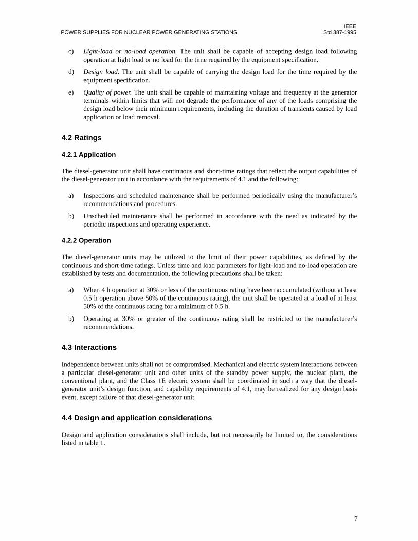
4.2.2 Operation
The diesel-generator units may be utilized to the limit of their power capabilities, as defined by thecontinuous and short-time ratings. Unless time and load parameters for light-load and no-load operation areestablished by tests and documentation, the following precautions shall be taken:
a) When 4 h operation at 30% or less of the continuous rating have been accumulated (without at least0.5 h operation above 50% of the continuous rating), the unit shall be operated at a load of at least50% of the continuous rating for a minimum of 0.5 h.
b) Operating at 30% or greater of the continuous rating shall be restricted to the manufacturer’srecommendations.
4.3 Interactions
Independence between units shall not be compromised. Mechanical and electric system interactions betweena particular diesel-generator unit and other units of the standby power supply, the nuclear plant, theconventional plant, and the Class 1E electric system shall be coordinated in such a way that the diesel-generator unit’s design function, and capability requirements of 4.1, may be realized for any design basisevent, except failure of that diesel-generator unit.
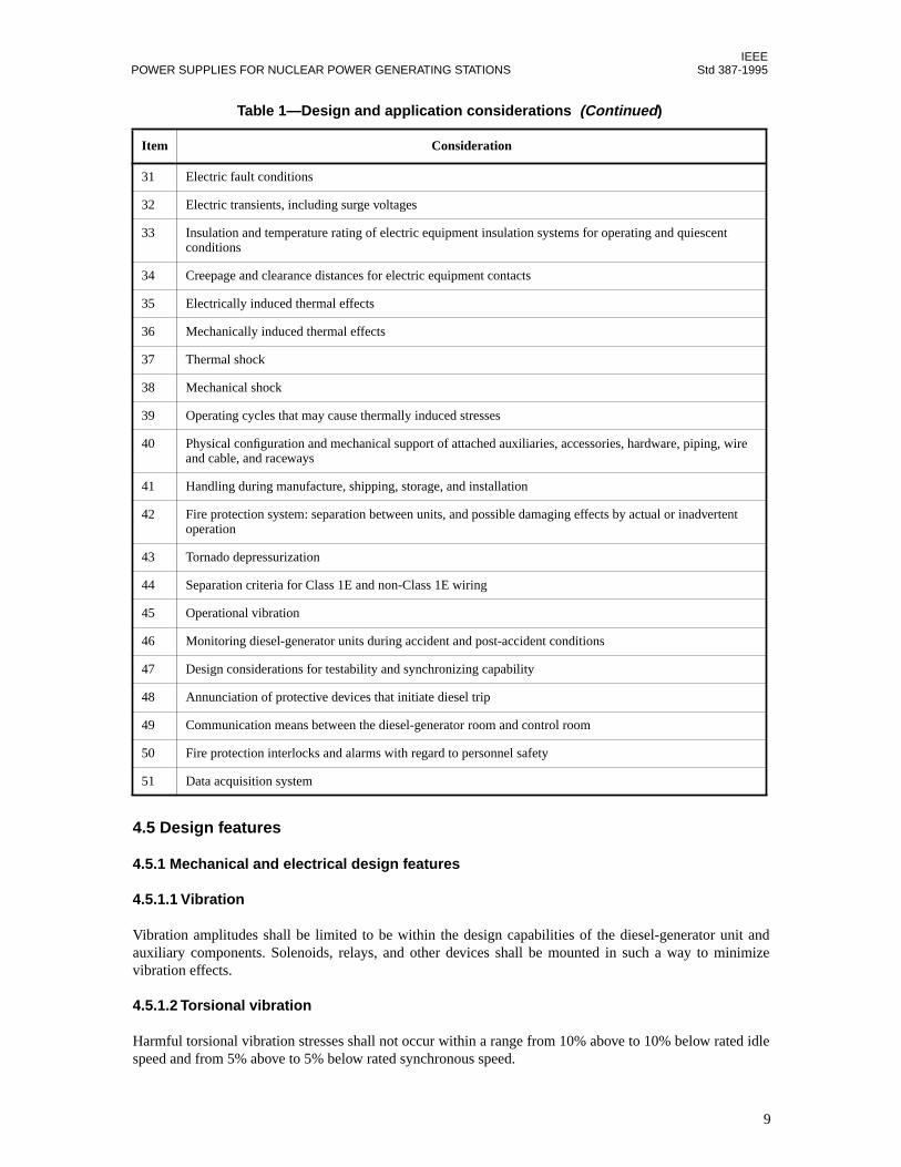
4.4 Design and application considerations
Design and application considerations shall include, but not necessarily be limited to, the considerationslisted in table 1.
7

IEEEStd 387-1995 IEEE STANDARD CRITERIA FOR DIESEL-GENERATOR UNITS APPLIED AS STANDBY
Table 1—Design and application considerations
Item Consideration
1 Avoidance of common failure mode between units of the standby power supply
2 Single failure criterion as applied to the standby power supply
3 Matching of the diesel engine, generator, excitation system, voltage regulator, and governor
4 Energy for operation of the control, protection, and surveillance systems
5 Control, protection, and surveillance systems
6 Lubrication system and equipment
7 Selection of air, water, or other means of cooling
8 Supply of cooling medium and ambient air temperature
9 Cooling system and equipment
10 Selection of electric, pneumatic, or other means of starting
11 Supply of starting energy
12 Starting system and equipment
13 Supply, temperature, and quality of combustion air
14 Combustion air system and equipment
15 Supply of fuel
16 Fuel supply system and equipment
17 Removal of products of combustion
18 Equipment design life
19 Service environment
20 Seismic design
21 Design load
22 Time available between receipt of start-diesel signal and initiation of load sequence
23 Description of loading sequence with time durations of application of individual loads
24 Maximum time available between receipt of start-diesel signal and acceptance of design load
25 Accommodation of loading sequence and time duration for application of individual loads
26 Load performance characteristics (transient and steady-state)
27 Continuous rating
28 Short-time rating
29 Light-load or no-load operation
30 Diesel-generator unit performance characteristics, including transient characteristics (cold/hot engine kW and generator step-change kVA) and any applicable engine derating due to service environment (see item 19)
8
IEEEPOWER SUPPLIES FOR NUCLEAR POWER GENERATING STATIONS Std 387-1995
4.5 Design features
4.5.1 Mechanical and electrical design features
4.5.1.1 Vibration
Vibration amplitudes shall be limited to be within the design capabilities of the diesel-generator unit andauxiliary components. Solenoids, relays, and other devices shall be mounted in such a way to minimizevibration effects.
4.5.1.2 Torsional vibration
Harmful torsional vibration stresses shall not occur within a range from 10% above to 10% below rated idlespeed and from 5% above to 5% below rated synchronous speed.
31 Electric fault conditions
32 Electric transients, including surge voltages
33 Insulation and temperature rating of electric equipment insulation systems for operating and quiescent conditions
34 Creepage and clearance distances for electric equipment contacts
35 Electrically induced thermal effects
36 Mechanically induced thermal effects
37 Thermal shock
38 Mechanical shock
39 Operating cycles that may cause thermally induced stresses
40 Physical configuration and mechanical support of attached auxiliaries, accessories, hardware, piping, wire and cable, and raceways
41 Handling during manufacture, shipping, storage, and installation
42 Fire protection system: separation between units, and possible damaging effects by actual or inadvertent operation
43 Tornado depressurization
44 Separation criteria for Class 1E and non-Class 1E wiring
45 Operational vibration
46 Monitoring diesel-generator units during accident and post-accident conditions
47 Design considerations for testability and synchronizing capability
48 Annunciation of protective devices that initiate diesel trip
49 Communication means between the diesel-generator room and control room
50 Fire protection interlocks and alarms with regard to personnel safety
51 Data acquisition system
Table 1—Design and application considerations (Continued)
Item Consideration
9

IEEEStd 387-1995 IEEE STANDARD CRITERIA FOR DIESEL-GENERATOR UNITS APPLIED AS STANDBY
4.5.1.3 Overspeed
Moving parts shall be designed to withstand that level of overspeed that results from a short-time rating loadrejection. Margin shall be provided to allow the overspeed device to be set sufficiently high to guarantee thatthe unit will not trip on short-time rating load rejection. As a minimum, the generator rotor, exciter rotor (ifused), and flywheel shall be designed to withstand an overspeed of 25% without damage.
4.5.1.4 Governor operation
If the diesel engine is equipped to operate in both the isochronous and the droop mode, provisions shall beincluded to automatically place the engine governor in the proper mode of operation when the diesel-generator unit is required to operate automatically (see 4.5.2.2).
4.5.1.5 Voltage regulator operation
If the voltage regulator is equipped to operate in the paralleled and nonparalleled mode, provisions shall beincluded to automatically place the voltage regulator in the proper mode of operation when the diesel-generator unit is required to operate automatically (see 4.5.2.2).
4.5.2 Control
4.5.2.1 Control modes
The diesel-generator unit shall be provided with control systems, permitting automatic and manual control.
4.5.2.2 Automatic control
Upon receipt of an emergency start-diesel signal, the automatic control system shall provide automatic start-up and automatic adjustment of speed and voltage to a ready-to-load condition.
a) A start-diesel signal shall override all other operating modes and return control of the diesel-generator unit to the automatic control system.
b) An emergency start-diesel signal shall not override any manual non-operating modes such as thosefor repair and maintenance.
4.5.2.3 Control points
Provisions shall be made for control both from the control room and external to the control room.
4.5.3 Surveillance
4.5.3.1 Surveillance systems
The diesel-generator unit shall be provided with surveillance systems permitting remote and local alarmsand indicating the occurrence of abnormal, pre-trip, or trip conditions.
4.5.3.2 Modes surveyed
As a minimum, the following conditions shall be surveyed:
a) Unit not runningb) Unit running, not loaded
10

IEEEPOWER SUPPLIES FOR NUCLEAR POWER GENERATING STATIONS Std 387-1995
c) Unit running, loadedd) Unit out of service
4.5.3.3 Surveillance instrumentation
The following systems shall have sufficient mechanical and electric instrumentation to survey the variablesrequired for successful operation and to generate the abnormal, pre-trip, and trip signals required for alarmof such conditions:
a) Starting systemb) Lubricating systemc) Fuel systemd) Primary cooling systeme) Secondary cooling systemf) Combustion air systemg) Exhaust systemh) Generatori) Excitation systemj) Voltage regulation systemk) Governor system
4.5.4 Protection
The diesel-generator unit shall be automatically tripped on an engine overspeed or generator differentialovercurrent, or both. Protective features, other than engine overspeed and generator differential current, shallbe
a) Blocked from automatically tripping the diesel-generator unit during an accident condition and shallbe annunciated in the plant control room, or
b) If protective features other than engine overspeed and generator differential current are retainedduring accident conditions, two or more independent measurements of each of these parameters withcoincident trip logic shall be provided. The design of the coincident trip logic circuitry shall providealarm for each individual sensor initiation. All protective devices shall remain effective during thediesel-generator unit testing, and during operation in non-accident conditions.
5. Factory production testing
5.1 General
5.1.1 Implementation
Testing shall be performed in accordance with a written test plan.
5.1.2 Documentation
Test documentation shall include the following:
a) Equipment performance specifications
b) Identification of the specific feature or features to be demonstrated by the test
c) Test plan
11
IEEEStd 387-1995 IEEE STANDARD CRITERIA FOR DIESEL-GENERATOR UNITS APPLIED AS STANDBY
d) Report of test results. The report shall include the following:
1) Objective
2) Equipment tested
3) Description of test facility (test setup), instrumentation used including calibration recordsreference, and test environment
4) Test procedures, including acceptance/rejection criteria
5) Test data and accuracy (results)
6) Test abnormalities and failures, including their disposition and effect on test results
7) Summary, conclusions, and recommendations
8) Supporting data
9) Approval signature and date
5.1.3 Analyses
Although testing is preferred, analyses may supplement test or be substituted for test, where testing is notpractical, to demonstrate conformance to the criteria stated in clause 4. Analysis shall include the basis ofassumptions used.
5.1.4 Substitutions
When tests are performed at the manufacturer’s or assembler’s facilities, and not at the site, the exhaustmuffler, intake air filter-silencer, and radiator (if applicable) normally used for shop tests may be substitutedin place of the equipment to be provided for a specific site, since it is not practical to utilize the equipmentand piping that will exist at the site or future sites for which the diesel-generator unit is being qualified.Results of tests shall be corrected to the condition of the service environment and design characteristics,including site exhaust muffler and intake air filter-silencer systems.
5.2 Factory production tests
The following tests are minimum requirements for factory production tests.
5.2.1 Engine tests
Each engine shall be tested, utilizing either a water brake dynamometer or a generator to provide accuratemeans to control power absorption. The following tests shall be performed:
a) Break-in test. Each manufacturer shall develop their own break-in schedule to best suit the engine.
b) Performance test.
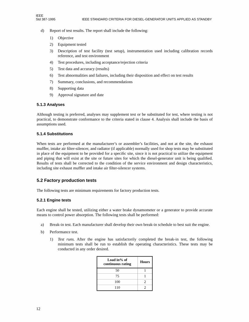
1) Test runs. After the engine has satisfactorily completed the break-in test, the followingminimum tests shall be run to establish the operating characteristics. These tests may beconducted in any order desired.
Load in% of continuous rating Hours
50 1
75 1
100 2
110 2
12

IEEEPOWER SUPPLIES FOR NUCLEAR POWER GENERATING STATIONS Std 387-1995
2) Data logging. Test logs of all of the above tests shall become a part of the records for aparticular engine. The test logs shall include at least the following data:
i) Speed (r/min)ii) Brake (hp or kW)iii) Brake specific fuel consumptioniv) Intake manifold pressurev) Intake manifold temperaturevi) Individual cylinder exhaust temperaturevii) Turbocharger exhaust temperatureviii) Jacket water temperature (engine inlet and outlet)ix) Jacket water pressure (engine inlet)x) Lube oil temperature (engine inlet and outlet)xi) Lube oil header pressure (engine inlet)xii) Type of fuel and fuel heat contentxiii) Barometric pressurexiv) Intake air temperature
3) Controls-alarm and shutdown. All engine-mounted alarms and shutdowns, where applicable,shall be set and checked. The points of activation shall be on the test logs.
4) Inspection. At any point after the break-in test or upon completion of the above test, a post-trialinspection shall be conducted. The manufacturer’s standard procedure shall be used. The resultsof the inspection shall be documented in the test report.
5.2.2 Generator tests
Generator testing shall be in accordance with NEMA MG 1-1993.
5.2.3 Excitation, control, and other accessories/auxiliaries
All such devices and assemblies shall be tested in accordance with the manufacturer’s standard practices.
6. Qualification requirements
6.1 General
The diesel-generator units applied as part of the standby power supply shall be qualified in accordance withthe requirements of this clause.9 This qualification will provide verification that the unit will meet therequirements of clause 4 under all expected environmental conditions. Qualification shall be accomplishedby performance of type tests on unaged equipment or by analysis, or by a combination of both as required in6.2 and by functional testing as required in 6.4 following any aging or seismic testing. All qualification shallbe performed in accordance with a written plan that defines analysis and tests to be performed, parameters tobe monitored during tests, test instrumentation, and acceptance criteria for equipment.
6.2 Initial type tests
Diesel-generators not previously type tested as standby power sources for nuclear power generating stationsshall be subject to a type testing program consisting of load capability, start and load acceptance, and margintests. It is preferred that these tests be performed at the engine manufacturer’s or assembler’s factory;
9The requirements for qualification in this clause are based on IEEE Std 323-1983 and IEEE Std 627-1980 as applicable to diesel-generator units to ensure that the equipment can perform within its specification requirements.
13

IEEEStd 387-1995 IEEE STANDARD CRITERIA FOR DIESEL-GENERATOR UNITS APPLIED AS STANDBY
however, they may be conducted at the site if certified calibration instrumentation is provided to measure andrecord the same functions and characteristics normally measured under factory testing conditions.
Type tests may be performed on one or more units, and qualification of one unit will qualify like units of thattype for equal or less severe service. If start and load acceptance tests (see 6.2.2) are performed using morethan one identical unit, then each of these units must be tested for load capability (see 6.2.1) and margin (see6.2.3).
Type tests shall be performed following successful completion of the factory production tests. Following thesuccessful completion of these type tests, the equipment shall be inspected in accordance with themanufacturer’s standard procedure, and inspection results shall be documented.
6.2.1 Load capability tests
These tests demonstrate the capability of the diesel-generator unit to carry the following rated loads at ratedpower factor for the period of time indicated, and to successfully reject load in accordance with 7.2.1.4. Onesuccessful completion of the test sequence shall satisfy this particular requirement.
a) Load equal to the continuous rating shall be applied for the time required to reach enginetemperature equilibrium.
b) Immediately following step a), the short-time rated load shall be applied for a period of 2 h and thecontinuous rated load shall be applied for a period of 22 h.
c) The short-time rating load rejection test shall be performed. The load rejection test will be accept-able if the increase in speed of the diesel engine does not exceed 75% of the difference betweennominal speed and the overspeed trip set point, or 15% above nominal, whichever is lower.
d) Light-load or no-load capability as described in 4.1.2 step c) shall be demonstrated by test. Light-load or no-load operation shall be followed by a load application ≥ 50% of the continuous kilowattrating for a minimum of 0.5 h.
6.2.2 Start and load acceptance tests
A series of tests shall be conducted to establish the capability of the diesel-generator unit to start and acceptload within the period of time necessary to satisfy the plant design requirement. An acceptable start and loadacceptance test is defined as follows; however, other methods with proper justification may be foundequivalent for the level of reliability to be demonstrated.10
A total of 100 valid start and load tests shall be performed with no failures allowed. Failure of the unit tosuccessfully complete this series of tests, as prescribed, will require a review of the system design adequacy,the cause of the failures to be corrected, and the tests continued until 100 valid tests are achieved without anyfailure. The start and load tests shall be conducted as follows:
a) Engine cranking shall begin upon receipt of the start-diesel signal, and the diesel-generator unit shallaccelerate to specified frequency and voltage within the required time interval.
b) Immediately following step a), the diesel-generator unit shall accept a single-step load ≥ 50% of thecontinuous kilowatt rating. Load may be totally resistive or a combination of resistive and inductiveloads.
c) At least 90 of these tests shall be performed with the diesel-generator unit initially at warm standby,based on jacket water and lube oil temperatures at or below values recommended by the engine man-
10While the reliability testing is not a specific requirement of IEEE Std 323-1983 or IEEE Std 627-1980, it is a required type test for thisequipment.
14
IEEEPOWER SUPPLIES FOR NUCLEAR POWER GENERATING STATIONS Std 387-1995
ufacturer. After load is applied, the diesel-generator unit shall continue to operate until jacket waterand lube oil temperatures are within ± 5.5 °C (± 10 °F) of the normal engine operating temperaturesfor the corresponding load.
d) At least 10 tests shall be performed with the engine initially at normal operating temperatureequilibrium defined as jacket water and lube oil temperatures within ± 5.5 °C (± 10 °F) of normaloperating temperatures, as established by the engine manufacturer for the corresponding load.
e) If the cause for failure to start or accept load in accordance with the preceding sequence falls underany of the categories listed below, that particular test shall be disregarded, and the test sequence shallbe resumed without penalty following identification and correction of the cause for the unsuccessfulattempt.
1) Unsuccessful start attempts that can definitely be attributed to operator error, including settingof alignment control switches, rheostats, or potentiometers, or other adjustments that may havebeen changed inadvertently prior to that particular start test.
2) Tests performed for verification of a scheduled maintenance procedure required during thisseries of tests. This maintenance procedure shall be defined prior to conducting the start andload acceptance tests and will then become a part of the normal maintenance schedule afterinstallation.
3) Tests performed in the process of troubleshooting. Each start attempt performed in the trouble-shooting process shall be defined as such before a start attempt is made.
4) Successful start attempts that were terminated intentionally without loading.
5) Failure of any of the temporary service systems such as dc power source, output circuit breaker,load, interconnecting piping and wiring, and any other temporary setup that will not be a part ofthe permanent installation.
6.2.3 Margin tests
Tests shall be conducted to demonstrate the diesel-generator unit capability to start and carry loads that aregreater than the magnitude of the most severe step load within the plant design load profile, including stepchanges above base load. The limiting case step change over base load as defined by the design load profileshall be demonstrated. This is not necessarily the largest step change, but may be a smaller step change asthe full-load capability of the diesel-generator unit is approached. These tests may be combined with theload capability or start and load acceptance tests. At least two margin tests shall be performed using eitherthe same or different load arrangement. A margin test load at least 10% greater than the magnitude of themost severe single-step load within the load profile is considered sufficient for the margin test. Thefrequency and voltage excursions recorded may exceed those values specified for the plant design load. Thecriteria for margin tests are as follows:
a) Demonstrate the ability of the generator and excitation system to accept the margin test load (usuallythe low power factor, high inrush, and high starting current of a pump motor) without experiencinginstability resulting in generator voltage collapse, or significant evidence of the inability of the volt-age to recover.
b) Demonstrate that there is sufficient engine torque available to prevent engine stall, and to permit theengine speed to recover, when experiencing the margin test load.
6.3 Aging
Aging methods are described in this clause for the applicable conditions listed in 4.1.2 step a), which aredetermined to be significant.
15

IEEEStd 387-1995 IEEE STANDARD CRITERIA FOR DIESEL-GENERATOR UNITS APPLIED AS STANDBY
6.3.1 Safety classification
Components and assemblies within the scope of this standard (see figure 1) shall be classified into one of thetwo following categories:
a) Components and assemblies required to enable the diesel-generator unit to meet its capabilities in4.1 (hereinafter called the safety-related function). These components and assemblies requireconsideration of aging as a potential cause for common mode failures. Examples may include thegovernor, generator, cable, excitation system, engine, starting air solenoid valves, and those gasketsand seals that are applied to prevent leakage that degrades unit performance.
b) Components and assemblies not required to perform a safety-related function. Each of thesenonsafety-related components or assemblies requires verification that it will not degrade the safety-related function. This may be accomplished by testing or analysis. Examples may include generatorresistance temperature detectors (RTDs), neutral grounding equipment, space heaters, starting aircompressors and drives, keep-warm heaters and pumps, and those gaskets and seals whose failurewill not degrade unit performance.
6.3.2 Aging classification
Further classification of the safety-related components identified in 6.3.1 step a) is required to address thepotential for age-related failures. The categories in table 2 illustrate this classification.
Components without significant age-related failure mechanisms may be excluded. For example, it isrecognized that cast iron used in the basic engine block will not represent a potential age-related failuremechanism over normal nuclear service life.
Following classification, those components with potential age-related failures shall be qualified by testing(the preferred method), analysis, or a combination of test and analysis. Components with a resultantidentified qualified life less than the overall qualified life objective shall have a maintenance/replacementinterval defined. If aging by test is used, it shall be followed by seismic qualification to meet IEEE Std 344-1987. In all cases, the documentation requirements in clause 6 of IEEE Std 323-1983 shall be satisfied. Anexample of this process is given in annex B.
Table 2—Format for component aging classification (see annex B)
Component Items with age-related failure mechanisms
Method of aging qualification
Items without age-related failure mechanisms
List specific component, e.g.,
GeneratorMotorEnginePumpControl panelsTanksGovernorsSolenoid valvesValves
List all items or materials within that component that have age-related failure mechanisms, e.g.,
GasketsInsulationBearings
List the method used, e.g.,
Accelerated agingPeriodic replacementAnalysis
List all items or materials within that component that do not have age-related failure mechanisms, e.g.,
Metal component
16

IEEEPOWER SUPPLIES FOR NUCLEAR POWER GENERATING STATIONS Std 387-1995
6.4 Seismic qualification requirements
Seismic qualification in accordance with IEEE Std 344-1987 is required for all safety-related components.Nonsafety-related components require analysis or test to show that they will not degrade the safety-relatedfunction of the unit during a seismic event. Seismic testing shall be followed by functional testing to verifythe applicable capabilities in clause 4.
6.5 Ongoing surveillance
Ongoing surveillance, including the periodic tests described in 7.4, may be used as a basis for theidentification of equipment degradation and validation of the results of the aging and aged equipment testingdescribed in 6.3.
6.5.1 Preventive maintenance, inspection, and testing
A separate preventive maintenance, inspection, and testing program (see also 6.5.2) shall be established forthe diesel-generator unit and all supporting systems based on the manufacturer’s recommendations,including time intervals for parts replacement of those components with a qualified life less than the unitqualified life objective. These recommendations may be based on operating hours or fixed time intervals, orboth. Procedures shall include, as a minimum, specific programs for each portion of the unit as follows:
a) The engine, including the governor, overspeed trip device, internal components to the maximumextent practical, turbocharger, lube oil components, fuel oil components, jacket water components,starting components, cleaning, adequate lubrication, and water chemistry
b) The generator and rotating exciter (if used), including insulation condition, bearings, coolingsystem, lubricating system, and space heaters (if applicable)
c) Electrical auxiliary equipment, including local engine and generator control, exciter and voltageregulator, and protection and surveillance components
d) Subsystems, including
1) Starting energy, typically consisting of air receiver tanks, compressors, piping, valves, andassociated instrument and control devices
2) Fuel oil, typically consisting of pumps, filters, strainers, piping, valves, and associatedinstrument and control devices
3) Lube oil, typically consisting of pumps, filters, strainers, keep-warm heaters and pumps,coolers, sump tanks, piping, valves, and associated instrument and control devices
4) Cooling water, typically consisting of expansion tanks, heat exchangers, pumps, keep-warmheaters and pumps, piping, valves, and associated instrument and control devices
5) Intake air, typically consisting of filters, silencers, expansion joints, and piping
6) Exhaust, typically consisting of silencers, expansion joints, and piping
7) Crankcase ventilation components, if applicable
6.5.2 Records and analysis
Records shall be maintained for each diesel-generator unit to provide a basis for an analysis of the unit’soverall performance. These records also provide a basis for verifying any assumptions made concerning age-related failure mechanisms. The documentation may also be used to shorten or extend the replacementintervals.
17

IEEEStd 387-1995 IEEE STANDARD CRITERIA FOR DIESEL-GENERATOR UNITS APPLIED AS STANDBY
6.6 Modifications
Modifications to a previously qualified diesel-generator unit, such as governor, generator, overall system fly-wheel effect, excitation system characteristics, cooling media, or other accessories/auxiliaries that maychange the capability or performance of a previously qualified diesel-generator unit, shall be analyzed todetermine if the degree of change is major or minor.
a) Major changes to a qualified engine, such as changes in stroke or bore, brake mean effectivepressure, speed, or diesel-generator arrangement in unique or different configuration shall berequalified in accordance with this clause.
b) Minor changes to a previously qualified diesel-generator unit, such as component parts substitution,shall be qualified by analysis or testing, or both.
6.7 Documentation
Qualification documentation shall be in accordance with IEEE Std 323-1983, and shall include thefollowing:
a) Service and environment [see 4.1.2 item a)]b) Classification table of all components as safety-related or nonsafety-relatedc) Analysis/justification for nonsafety-related componentsd) Classification table of safety-related components with or without age-related failure mechanismse) Justification of aging methods for various componentsf) Test data for control panels, exciter/regulator (including seismic)g) Test data for insulation systems testingh) Test data for seismic testing of smaller mechanical componentsi) Analytical data for seismic analysis of generator, engine, and major mechanical componentsj) Historical data/justification for items requiring periodic replacementk) Correlation of qualification program to instruction book information for periodic replacement, etc.
7. Site testing
7.1 Testing
Site testing shall consist of site acceptance testing, pre-operational testing, and periodic testing. Individualtests shall be as shown in table 3.
7.2 Site acceptance testing
After final assembly and preliminary start-up testing, each diesel-generator unit shall be tested at the site todemonstrate the capability of the unit to perform its intended function.
7.2.1 Tests
The tests to be given to the diesel-generator unit are shown in table 3 and shall be as follows.
7.2.1.1 Starting test
Starting tests shall demonstrate the capability to attain and stabilize frequency and voltage within the limitsand time defined in the equipment specification.
18

IEEEPOWER SUPPLIES FOR NUCLEAR POWER GENERATING STATIONS Std 387-1995
Table 3—Site testing
Reference Tests
Site acceptance
tests(7.2)
Pre-operational
tests(7.3)
Availability tests(7.4.2.1)
Monthly 6 Monthly
System operation
tests— shutdown/refueling(7.4.2.2)
Indepen-dence tests
10 years(7.4.2.3)
7.2.1.1 Starting X
7.2.1.2 Load acceptance
X
7.2.1.3 Rated load X
7.2.1.4 Load rejection
X
7.2.1.5 Electrical X
7.2.1.6 Subsystem X
7.3.3 Reliability X
7.5.1 Start X
7.5.2 Load run X X
7.5.3 Fast start X
7.5.4 LOOP X
7.5.5 SIAS X
7.5.6 Combined SIAS and LOOP
X X
7.5.7 Largest load rejection
X X
7.5.8 Design load rejection
X X
7.5.9 Endurance and load
Xa
aInstead of 2 h and 6 h, use 2 h and 22 h.
X
7.5.10 Hot restart X X
7.5.11 Synchroni-zing
X X
7.5.12 Protective trip bypass
X X
7.5.13 Test mode override
X X
7.5.14 Independence X X
19

IEEEStd 387-1995 IEEE STANDARD CRITERIA FOR DIESEL-GENERATOR UNITS APPLIED AS STANDBY
7.2.1.2 Load acceptance test
Load acceptance tests shall demonstrate the capability to accept the individual loads that make up the designload, as described in 3.4, in the desired sequence and time duration and to maintain the voltage and fre-quency within the acceptable limits.
NOTE—If the diesel-generator unit has a light-load or no-load operation capability, the load acceptance test sequenceshall include consideration of the potential effects on load acceptance following such operation (see also 4.2.2).
7.2.1.3 Rated load test
Rated load tests shall demonstrate the capability of carrying the following loads for the indicated timeswithout exceeding the manufacturer’s design limits:
a) A load equal to the continuous rating for the time required to reach engine temperature equilibriumplus 1 h
b) Immediately following the load in item a), the rated short-time load shall be applied for a period of2 h
7.2.1.4 Load rejection test
Load rejection tests shall demonstrate the capability of rejecting short-time rated load without exceedingspeeds or voltages that will cause tripping or component damage.
7.2.1.5 Electrical test
Electrical tests shall demonstrate that the electrical properties of the generator, excitation system, voltageregulation system, engine governor system, and the control and surveillance systems are acceptable for theintended application.
7.2.1.6 Subsystem test
Tests shall demonstrate the capability of the control, protection, and surveillance systems to function inaccordance with the requirements of the intended application.
7.2.2 Test loads
Loads to be applied, carried, and rejected during site testing shall be the design load auxiliaries located at thestation. Equivalent loads may be used if these auxiliaries cannot be operated for testing.
7.3 Pre-operational testing
Following completion of the site acceptance testing, pre-operational tests shall be performed to demonstratestarting and operational adequacy of the diesel-generators and the system.
The individual pre-operational tests shall be as indicated in table 3 and as described in 7.5.
Reliability tests shall demonstrate that an acceptable level of reliability has been achieved to place the newdiesel-generators into operation. This shall be achieved by a minimum of 25 valid start and load tests withoutfailure on each installed diesel-generator.
20

IEEEPOWER SUPPLIES FOR NUCLEAR POWER GENERATING STATIONS Std 387-1995
7.4 Periodic testing
7.4.1 General
After being placed in service, the diesel-generator unit shall be tested periodically to demonstrate that thecontinued capability and availability of the unit to perform its intended function is acceptable. Records andanalysis described in 7.6 shall be maintained for all periodic tests. It is recognized that some of these testsmay be combined and not necessarily performed individually. It is not necessary to begin these tests fromstandby conditions unless otherwise specified.
a) Test equipment shall not cause a loss of independence between redundant diesel-generator units orbetween diesel-generator load groups.
b) Periodic testing of a diesel-generator unit shall not impair the capability of the unit to supplyemergency power in the required time in response to start-diesel signals.
c) All diesel-generator unit protective trips and alarms should be operative during applicable periodictesting.
d) Written procedures for testing shall be prepared and utilized. The procedures shall include themanufacturer’s applicable test recommendations and shall identify all special arrangements orchanges in the normal system configuration required to perform the test. The procedures shall ensurethat the system is restored to its normal configuration after completion of the tests. All tests shall bein general accordance with the manufacturer’s recommendations for reducing engine wear,including cool-down operation at reduced power followed by post-operation lubrication.
Test procedures that involve starting and stopping the diesel-generator unit shall include thefollowing steps that are pertinent to each specific test:
1) Observe and record all pre-start data listed in table 4.
2) Initiate the start-diesel signal and measure and record the elapsed time from the start-dieselsignal to rated speed.
3) Confirm that the generator voltage and frequency are maintained within the prescribed limitsfor the particular circumstances of each test.
4) Record all parameters listed in table 4 at the beginning of any load-carrying test and at the endof any load-carrying test and at 1 h intervals during the test, if applicable. The data should berecorded under similar conditions for use in trending analyses.
5) Observe and record all post-test data listed in table 4 after completion of the test.
e) Communication shall be established between the diesel-generator unit testing location and the maincontrol room so that operators are cognizant of the status of the diesel-generator unit undergoing thetest.
f) During system operational tests, problems may arise with individual components that do not detractfrom the overall test purpose. These components shall be repaired and their interface with the systemshall be retested; however, the total test need not be repeated unless necessary due to the criticalfunction of the component involved.
Abnormal conditions discovered during any test shall be evaluated to determine if
1) The condition would prevent the diesel-generator unit from performing its intended function.2) The test is a valid test.
7.4.2 Periodic tests
Periodic tests shall consist of availability, system operation, and independence verification tests.
21

IEEEStd 387-1995 IEEE STANDARD CRITERIA FOR DIESEL-GENERATOR UNITS APPLIED AS STANDBY
7.4.2.1 Availability tests
These tests demonstrate the continued capability of the diesel-generators to start and accept load.
Each diesel-generator unit shall be started and loaded at least once in 31 days (slow-start and load-run test).In lieu of the above test, once every six months a fast-start and load-run test shall be performed.
Table 4—Test parameters
Parametera
aThese parameters are considered the minimum requirements for this standard. Additional parametersmay be added for performance measurements.
Pre-start During test Post-test
Pressures
Lube oil: engine - inlet
Lube oil: turbo - inlet
Lube oil: engine - filter differential
Lube oil: turbo - filter differential
Lube oil: engine header
Lube oil: filter differential
Crankcase
Starting air
X
X
X
X
X
X
X
X
X
X
X
Temperatures
Lube oil: engine - inlet and outlet
Jacket water: engine - inlet and outlet
Exhaust: each power cylinder
Exhaust: turbo outlet
Exhaust: exhaust manifold (if applicable)
X
X
X
X
X
X
X
Electrical
Frequency
Power
Reactive
Current: generator - all phases
Voltage: generator - all phases
Current: field
X
X
X
X
X
X
Level
Lube oil: engine generator crankcase
Lube oil: generator bearing
Jacket water: standpipe or expansion tank
X
X
X
X
X
X
22

IEEEPOWER SUPPLIES FOR NUCLEAR POWER GENERATING STATIONS Std 387-1995
7.4.2.2 System operation tests
This series of tests demonstrates the ability of the diesel-generator unit to perform its intended functionunder simulated accident conditions. These tests shall be performed at shutdown/refueling outages onceevery two years.
7.4.2.3 Independence verification test
Subsequent to any modifications where diesel-generator unit independence may have been affected, or every10 years during a plant shutdown or refueling outage, whichever is the shorter, an independent verificationtest shall be conducted.
7.5 Test descriptions
The following descriptions apply to the tests listed in table 3. These tests should be preceded by a pre-lubeperiod and should be in general accordance with the manufacturer’s recommendations for reducing enginewear, including cool-down operation at reduced power followed by post-operation lubrication. Unlessotherwise noted, these tests should be performed at a power factor as close as practical to the design loadpower factor as plant voltage conditions permit.
7.5.1 Slow-start test
Demonstrate proper start-up from standby conditions and verify that the required design voltage andfrequency are attained. The unit should reach rated speed on a prescribed schedule selected to minimizestress and wear on the diesel-generator unit.
7.5.2 Load-run test
Demonstrate load-carrying capability, with load equivalent to 90–100% of the continuous rating of thediesel-generator unit, for an interval of not less than 1 h and until temperature equilibrium has been attained.This test may be accomplished by synchronizing the generator with offsite power. Testing may be performedat unity power factor or at a lagging power factor within the diesel-generator unit capability. The loading andunloading of a diesel-generator unit during this test should be gradual and based on a prescribed scheduleselected to minimize stress and wear on the diesel-generator unit.
7.5.3 Fast-start test
Demonstrate that each diesel-generator unit starts from standby conditions (if a plant has normally operatingpre-warm systems, this would constitute its standby conditions) and verify that the diesel-generator unitreaches required voltage and frequency within acceptable limits and time, as defined in the plant technicalspecifications.
7.5.4 Loss-of-offsite power (LOOP) test
Demonstrate by simulating a loss of offsite power that
a) The emergency buses are de-energized and the loads are shed from the emergency buses.
b) The diesel-generator unit starts on the auto-start signal from its standby conditions, attains therequired voltage and frequency within acceptable limits and time, energizes the auto-connected shut-down loads through the load sequencer, and operates for a minimum of 5 min.
23
IEEEStd 387-1995 IEEE STANDARD CRITERIA FOR DIESEL-GENERATOR UNITS APPLIED AS STANDBY
7.5.5 Safety injection actuation signal (SIAS) test
Demonstrate that on a SIAS, the diesel-generator unit starts on the auto-start signal from its standbyconditions, attains the required voltage and frequency within acceptable limits and time, and operates onstandby for a minimum of 5 min.
7.5.6 Combined SIAS and LOOP test
Demonstrate by simulating a loss of offsite power in conjunction with SIAS that
a) The emergency buses are de-energized and the loads are shed from the emergency buses.
b) The diesel-generator unit starts on the auto-start signal from its standby conditions, attains therequired voltage and frequency within acceptable limits and time, energizes the auto-connected shut-down loads through the load sequencer, and operates for a minimum of 5 min.
7.5.7 Largest-load rejection test
Demonstrate the emergency diesel-generator unit’s capability to reject a loss of the largest single load, andverify that the voltage and frequency requirements are met and that the unit will not trip on overspeed.
7.5.8 Design-load rejection test
Demonstrate the diesel-generator unit’s capability to reject a load equal to 90–100% of the design loads, andverify that the unit will not trip on overspeed.
7.5.9 Endurance and load test
Demonstrate load-carrying capability for an interval of not less than 8 h, of which 2 h should be at a loadequivalent to the short-time rating of the diesel-generator unit and 6 h at a load equivalent to 90–100% of thecontinuous rating. (For the pre-operational test, use 2 h and 22 h.) Verify that voltage and frequencyrequirements are maintained.
7.5.10 Hot restart test
Demonstrate hot restart functional capability at full-load temperature conditions by verifying that the diesel-generator unit starts on a manual or auto-start signal, attains the required voltage and frequency withinacceptable limits and time, and operates for a minimum of 5 min.
7.5.11 Synchronizing test
Demonstrate the ability to
a) Synchronize the diesel-generator unit with offsite power while the unit is connected to theemergency load.
b) Transfer this load to the offsite power.
c) Isolate the diesel-generator unit.
d) Restore the diesel-generator unit to standby status.
7.5.12 Protective-trip bypass test
Demonstrate that specified automatic diesel-generator unit trips are automatically bypassed as designed.Typically, engine overspeed and generator differential current trip are not bypassed.
24

IEEEPOWER SUPPLIES FOR NUCLEAR POWER GENERATING STATIONS Std 387-1995
7.5.13 Test mode override test
Demonstrate that with the diesel-generator unit operating in the automatic test mode while connected to itsbus, a simulated safety injection signal overrides the test mode by
a) Returning the diesel-generator unit to standby operations.b) Automatically energizing the emergency loads from offsite power.
7.5.14 Independence test
Demonstrate that, by starting and running (unloaded) redundant units simultaneously, potential commonfailure modes that may be undetected in single diesel-generator unit tests do not occur.
7.6 Records
Records shall be maintained for each diesel-generator unit to provide a basis for an analysis of the unit’soverall performance. The records shall be retrievable and shall provide a basis for verifying any assumptionsmade. The documentation may also be used to shorten or extend the replacement intervals or to extendequipment or station life. The records shall include, as a minimum, the following features:
a) All start attempts, including those from bona fide signals; maintenance, repair, and out-of-servicetime histories, as well as cumulative maintenance and operating data; cumulative statistical analysisof diesel-generator unit test results, together with results of operation of the diesel-generator unitwhen required by actual demand
b) Critical failure mechanisms, human errors, and common mode failures, including cause andcorrective action
c) Test parameter data indicated in table 4 that may have application for reliability and data trending
25

IEEEStd 387-1995 IEEE STANDARD CRITERIA FOR DIESEL-GENERATOR UNITS APPLIED AS STANDBY
26

IEEEPOWER SUPPLIES FOR NUCLEAR POWER GENERATING STATIONS Std 387-1995
Annex A
(informative)
Method for establishing a load profile for a diesel-generator unit
The load profile shows the magnitude and duration of loads applied in a prescribed time sequence, includingthe transient and steady-state characteristics of the individual loads for the most severe conditions, includingboth the automatically and manually sequenced loads. The diesel-generator unit is typically specified in thedesign stage, before the actual characteristics of these loads are known. Most of these loads are applied tothe diesel-generator unit in a combination of block loads, sequenced to best suit the design objectives of thepower plant. The majority of these loads are induction motors. Knowledge of the characteristics of each loadwithin the block load is essential to establish the rating of the diesel-generator unit, a critical application foraccelerating large loads in rapid succession. To avoid confusion, the following data should be established toproperly size the unit:
a) Available time to attain rated conditions preceding initial load acceptance
b) Identification of each load block and its application with respect to time sequence
c) Type of loads in each load block, e.g., transformer, induction motor or resistive load, pump, fan, etc.
d) Load characteristics:
1) Transformer loads:
i) Rated kilovoltamperes, percent impedance (minimum specified), or inrush kilovoltam-peres at rated voltage
ii) Connected load (power factor and characteristics)
iii) Efficiency
2) Resistive loads: kilowatts at rated voltage
3) Motor loads:
i) Rated nameplate voltage, frequency, and speed
ii) Rated nameplate horsepower and horsepower at maximum operating conditions; for theseconditions include current, power factor, and efficiency
iii) Locked rotor characteristics at rated voltage, including starting power factor and lockedrotor current (as percent of full load rating)
iv) Acceleration conditions at rated and minimum required starting voltage, e.g., 75%,including starting profile as shown in figure A.1
NOTE—Depressed voltage below rated value at the motor terminals, resulting from transformer and distribution losses,will affect motor characteristics and should be identified.
Typical large motor characteristic values are:
— Horsepower, voltage, and frequency (nameplate)— Locked rotor current (inrush) = 6.0–6.5 times rated (approximately 5.5–6.0 kVA/hp)— Locked rotor power factor = 20%— Breakdown kilowatts = 2.2 hp (typical)— Running efficiency = 92%— Running power factor = 85%— Accelerating time = 2.5–4.0 s (loaded), 1.5 s (unloaded)
27
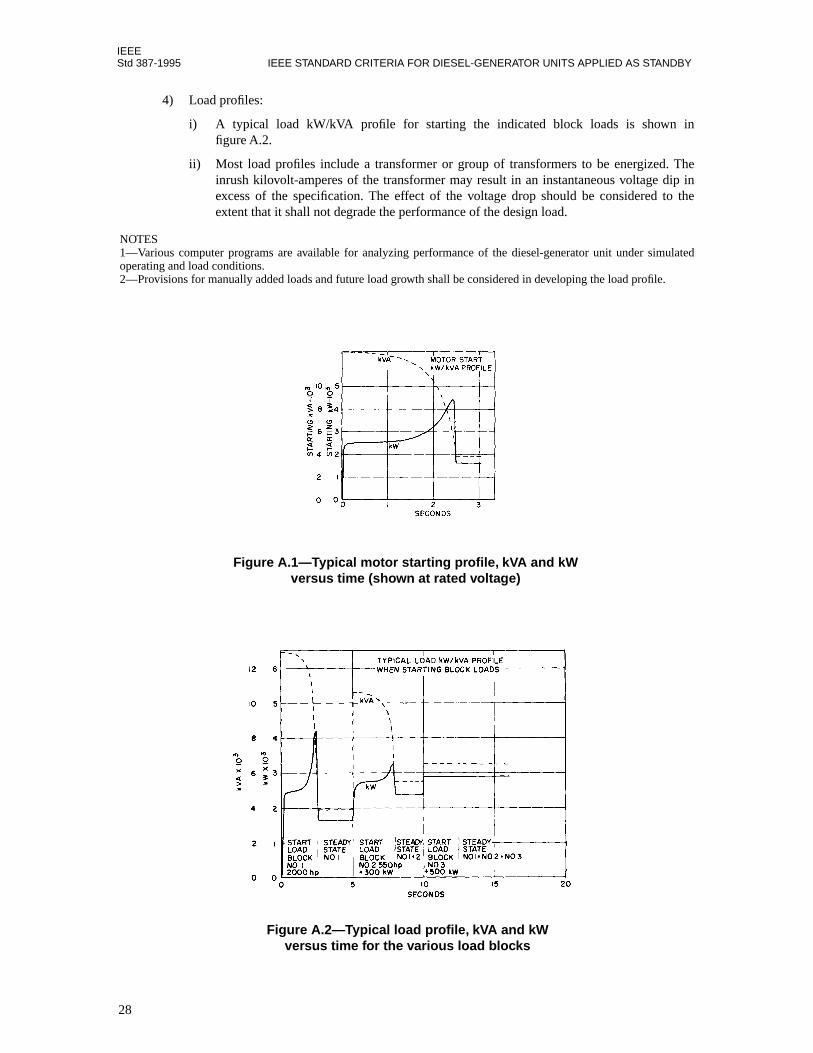
IEEEStd 387-1995 IEEE STANDARD CRITERIA FOR DIESEL-GENERATOR UNITS APPLIED AS STANDBY
4) Load profiles:
i) A typical load kW/kVA profile for starting the indicated block loads is shown infigure A.2.
ii) Most load profiles include a transformer or group of transformers to be energized. Theinrush kilovolt-amperes of the transformer may result in an instantaneous voltage dip inexcess of the specification. The effect of the voltage drop should be considered to theextent that it shall not degrade the performance of the design load.
NOTES1—Various computer programs are available for analyzing performance of the diesel-generator unit under simulatedoperating and load conditions.2—Provisions for manually added loads and future load growth shall be considered in developing the load profile.
Figure A.1—Typical motor starting profile, kVA and kW versus time (shown at rated voltage)
Figure A.2—Typical load profile, kVA and kWversus time for the various load blocks
28
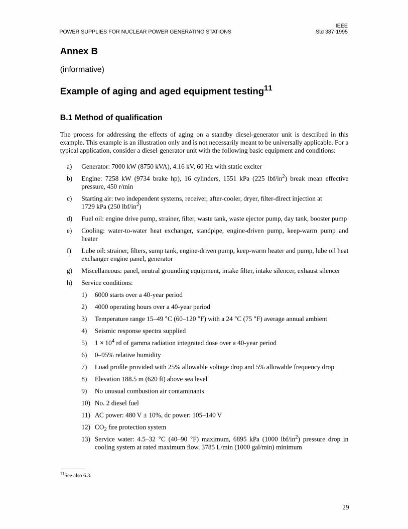
IEEEPOWER SUPPLIES FOR NUCLEAR POWER GENERATING STATIONS Std 387-1995
Annex B
(informative)
Example of aging and aged equipment testing11
B.1 Method of qualification
The process for addressing the effects of aging on a standby diesel-generator unit is described in thisexample. This example is an illustration only and is not necessarily meant to be universally applicable. For atypical application, consider a diesel-generator unit with the following basic equipment and conditions:
a) Generator: 7000 kW (8750 kVA), 4.16 kV, 60 Hz with static exciter
b) Engine: 7258 kW (9734 brake hp), 16 cylinders, 1551 kPa (225 lbf/in2) break mean effectivepressure, 450 r/min
c) Starting air: two independent systems, receiver, after-cooler, dryer, filter-direct injection at1729 kPa (250 lbf/in2)
d) Fuel oil: engine drive pump, strainer, filter, waste tank, waste ejector pump, day tank, booster pump
e) Cooling: water-to-water heat exchanger, standpipe, engine-driven pump, keep-warm pump andheater
f) Lube oil: strainer, filters, sump tank, engine-driven pump, keep-warm heater and pump, lube oil heatexchanger engine panel, generator
g) Miscellaneous: panel, neutral grounding equipment, intake filter, intake silencer, exhaust silencer
h) Service conditions:
1) 6000 starts over a 40-year period
2) 4000 operating hours over a 40-year period
3) Temperature range 15–49 °C (60–120 °F) with a 24 °C (75 °F) average annual ambient
4) Seismic response spectra supplied
5) 1 × 10⁴ rd of gamma radiation integrated dose over a 40-year period
6) 0–95% relative humidity
7) Load profile provided with 25% allowable voltage drop and 5% allowable frequency drop
8) Elevation 188.5 m (620 ft) above sea level
9) No unusual combustion air contaminants
10) No. 2 diesel fuel
11) AC power: 480 V ± 10%, dc power: 105–140 V
12) CO2 fire protection system
13) Service water: 4.5–32 °C (40–90 °F) maximum, 6895 kPa (1000 lbf/in2) pressure drop incooling system at rated maximum flow, 3785 L/min (1000 gal/min) minimum
11See also 6.3.
29

IEEEStd 387-1995 IEEE STANDARD CRITERIA FOR DIESEL-GENERATOR UNITS APPLIED AS STANDBY
Following definition of the equipment and its conditions, the components are analyzed and categorized assafety related or nonsafety related. Justification is documented for those items categorized as nonsafety,typically as shown in table B.1.
For each of the items in table B.1, seismic analysis or testing is documented to ensure there will be no inter-ference with the safety-related function of other components.
The next step in the process is to categorize all safety-related components as components with or withoutage-related failure mechanisms. Components with age-related failure mechanisms are required to be testedor analyzed to determine their respective qualified life. Components that are in the non-aging categoryrequire justification to show why they would not age under the circumstances. As described in 6.3.2 of thisstandard, this may be presented in tabular form.
Table B.2 illustrates some specific examples of the classification method.
Following identification and classification, the qualification shall be accomplished. Testing of the variouscomponents is preferred. For the control panels, the individual applicable components are aged, assembledin the unit or on a fixture (simulated mounting), and seismically tested. Documentation of post-testoperational parameters is required. Burn-in of a unit with electronic components may be a part of thequalification process. For the generator, aging testing of winding materials is performed followed by seismicsimulation. The generator assembly, overall, is seismically analyzed according to IEEE Std 344-1987.12 Formechanical components, seismic analysis is accomplished where testing is impractical (e.g., air receivers,engines, and smaller mechanical off-engine components such as pumps, filters, strainers, etc.).
Complete documentation of all seismic test and analysis is required.
Radiation testing is not required for this example; a brief material analysis is sufficient.
Table B.1—Examples of nonsafety related components
Examples of nonsafety related components Discussion
Starting air compressor/dryer These components and any other items upstream of the safety-related isolation check valve are nonsafety related.
Neutral grounding transformer/resistor Analysis of electrical system shows that possible failure modes (short, ground, open circuit) will not affect safety-related function, thus no electrical isolation is required.
Lube oil keep-warm pump and heater The lube oil system is safety related, but these components are not. Pumping and heating of lube oil improves starting time and overall performance (only slightly), but is not required for a 10 s start and loading. Analysis or test is required to verify that, with the keep-warm systems inoperable, the 10 s criteria is still met.
12Standards referenced in this annex can be found in B.2.
30

IEEEPOWER SUPPLIES FOR NUCLEAR POWER GENERATING STATIONS Std 387-1995
Table B.2—Aging classifications of safety-related components
ComponentItems with age-related failure mechanisms
Method of aging qualification Items without age-related failure mechanisms
Generator Insulation materials
Bearings
Brushes
Accelerated aging per IEEE Std 275-1992
Abnormal wear identified through periodic testing and possible replacement
Expected life based on operating experience and replacement interval identified (normal maintenance)
Rotor and statorsteel
aging insignificantUninsulated over 40 year copper wire objective
Copper busbar
Class 1E ac motors
Insulation materials
Bearings
Accelerated aging per IEEE Std 117-1974 and IEEE Std 275-1992 or IEEE Std 334-1994
Abnormal wear identified through periodic testing and possible replacement
Rotor and stator steel
Control panels
Circuit breakers and switches
Electromechanical relays
Wire and cable including connectors and terminals
Mechanical fatigue is predominant failure mode. Cycle 4000 times and accelerate age coils (as applicable) prior to seismic testing of panel.
Analyze operating modes and cycle accordingly. Accelerate age coil system per IEEE Std 117-1974 and IEEE Std 275-1992.
Accelerated age per IEEE Std 383-1974
Panel steel aging insignificantCopper busbar over 40 year objective
Wireways material analysisCircuit board and justificationmaterials required
Governor/tachometer and control
Gaskets ando-rings
Expected life based on operating experience and replacement interval identified (normal maintenance)
Metal chassisCertain electronic components: silicon semiconductors, resistors, ceramic capacitors, dry paper and film capaci-tors (reference discussion in IEEE Std 650-1990 and analyze application accordingly)
31

IEEEStd 387-1995 IEEE STANDARD CRITERIA FOR DIESEL-GENERATOR UNITS APPLIED AS STANDBY
Static exciter/voltage regulator
Transformers and other magnetic components’ insulation systems
Electrolytic capacitors
Circuit breakers, relays, switches
Wire and cable
Accelerated aging per IEEE Std 117-1974 and IEEE Std 275-1992. Transformers per IEEE Std 259-1994.
Expected life data from manufacturer used as guide to determine required periodic replacement interval
Mechanical fatigue is predominant failure mode. Cycle 4000 times and accelerate age coils (as applicable) prior to seismic testing of panel.
Accelerated age per IEEE Std 383-1974
Metal chassisCertain electronic components: silicon semiconductors, resistors, ceramic capacitors, dry paper and film capaci-tors (reference discussion in IEEE Std 650-1990 and analyze application accordingly)
Brushless exciter
Winding insulation Accelerated aging per IEEE Std 117-1974 and IEEE Std 275-1992
Rotor and stator steel
Starting air solenoid valves
Coil insulation;gasket, o-rings, discs, wire and cable
Accelerated aging per IEEE Std 117-1974 and IEEE Std 275-1992. Periodic replacement interval as required. Accelerated aging per IEEE Std 383-1974.(NOTE—The above is all inclusive; however, an overall program similar to IEEE Std 382-1985 is acceptable.)
Metal enclosure
Engine and mechanical auxiliaries
Gaskets, o-rings, seals, etc.
Metallic components subject to wear (valves, pistons, bearings, etc.)
Expected life based on operating experience and replacement interval identified (normal maintenance)
Abnormal wear identified through periodic testing and inspection, followed by possible replacement
Metallic components not subject to wear
Table B.2—Aging classifications of safety-related components (Continued)
ComponentItems with age-related failure mechanisms
Method of aging qualification Items without age-related failure mechanisms
32
IEEEPOWER SUPPLIES FOR NUCLEAR POWER GENERATING STATIONS Std 387-1995
B.2 Bibliography
[B1] IEEE Std 117-1974 (Reaff 1991), IEEE Standard Test Procedure for Evaluation of Systems ofInsulating Materials for Random-Wound AC Electric Machinery (ANSI).
[B2] IEEE Std 259-1994, IEEE Standard Test Procedure for Evaluation of Systems of Insulation forSpecialty Transformers (ANSI).
[B3] IEEE Std 275-1992, IEEE Recommended Practice for Thermal Evaluation of Insulation Systems forAlternating-Current Electric Machinery Employing Form-Wound Preinsulated Stator Coils for MachinesRated 6900 V and Below (ANSI).
[B4] IEEE Std 334-1994, IEEE Standard for Qualifying Continuous Duty Class 1E Motors for NuclearPower Generating Stations (ANSI).
[B5] IEEE Std 344-1987 (Reaff 1993), IEEE Recommended Practice for Seismic Qualification of Class 1EEquipment for Nuclear Power Generating Stations (ANSI).
[B6] IEEE Std 382-1985, IEEE Standard for Qualification of Actuators for Power Operated ValveAssemblies With Safety-Related Functions for Nuclear Power Plants (ANSI).
[B7] IEEE Std 383-1974 (Reaff 1992), IEEE Standard for Type Test of Class 1E Electric Cables, FieldSplices, and Connections for Nuclear Power Generating Stations (ANSI).
[B8] IEEE Std 650-1990, IEEE Standard for Qualification of Class 1E Static Battery Chargers and Invertersfor Nuclear Power Generating Stations (ANSI).
33

IEEEStd 387-1995 IEEE STANDARD CRITERIA FOR DIESEL-GENERATOR UNITS APPLIED AS STANDBY
34

IEEEPOWER SUPPLIES FOR NUCLEAR POWER GENERATING STATIONS Std 387-1995
Annex C
(informative)
Recommended diesel-generator unit monitoring and trending parameters
C.1 General
The industry and regulatory philosophy is shifting away from reliance on statistical testing and towardmonitoring and trending to facilitate aging/reliability determinations. This annex lists parameters and givesinformation generally useful for this purpose. The required data may be obtained by monthly testing. Thetest duration should be adequate to obtain several sets of data to confirm engine and generator operability.
C.2 Purpose
The purpose of the monthly tests is to perform a “health check” of the engine and generator system. If mostof the recommended parameters are checked each month, immediate engine condition is determined. Bytrending certain parameters, the long-term degradation mechanisms can also be determined. Theseparameters may be recorded each month for unit management purposes.
C.3 Recommended parameters
Table C.1 lists monitoring and trending parameters generally useful for determining the status of importantengine and generator parameters. Many installations have the necessary sensors and gages already in placeto obtain this data. Some installations have fewer sensors and gages installed. Where additional sensors andgages are needed, commercial grade components may be installed since the data is advisory in nature. Thesecommercial grade components would not jeopardize the unit safety function if they fail to operate.
The regular review and use of these recommended parameters should increase the unit reliability and reduceaging concerns by detecting substandard performance early before failures occur. Monitoring and trendinguse in diesel-generator unit management is now generally considered more practical for reliability assurancethan depending upon start and run statistical information.
35
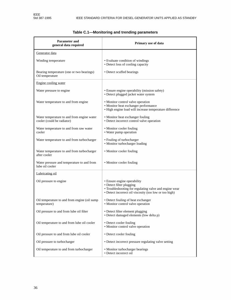
IEEEStd 387-1995 IEEE STANDARD CRITERIA FOR DIESEL-GENERATOR UNITS APPLIED AS STANDBY
Table C.1—Monitoring and trending parameters
Parameter andgeneral data required Primary use of data
Generator data
Winding temperature
Bearing temperature (one or two bearings)Oil temperature
• Evaluate condition of windings• Detect loss of cooling capacity
• Detect scuffed bearings
Engine cooling water
Water pressure to engine
Water temperature to and from engine
Water temperature to and from engine water cooler (could be radiator)
Water temperature to and from raw water cooler
Water temperature to and from turbocharger
Water temperature to and from turbocharger after cooler
Water pressure and temperature to and from lube oil cooler
• Ensure engine operability (mission safety)• Detect plugged jacket water system
• Monitor control valve operation• Monitor heat exchanger performance• High engine load will increase temperature difference
• Monitor heat exchanger fouling• Detect incorrect control valve operation
• Monitor cooler fouling• Water pump operation
• Fouling of turbocharger• Monitor turbocharger loading
• Monitor cooler fouling
• Monitor cooler fouling
Lubricating oil
Oil pressure to engine
Oil temperature to and from engine (oil sump temperature)
Oil pressure to and from lube oil filter
Oil temperature to and from lube oil cooler
Oil pressure to and from lube oil cooler
Oil pressure to turbocharger
Oil temperature to and from turbocharger
• Ensure engine operability• Detect filter plugging• Troubleshooting for regulating valve and engine wear• Detect incorrect oil viscosity (too low or too high)
• Detect fouling of heat exchanger• Monitor control valve operation
• Detect filter element plugging• Detect damaged elements (low delta p)
• Detect cooler fouling• Monitor control valve operation
• Detect cooler fouling
• Detect incorrect pressure regulating valve setting
• Monitor turbocharger bearings• Detect incorrect oil
36
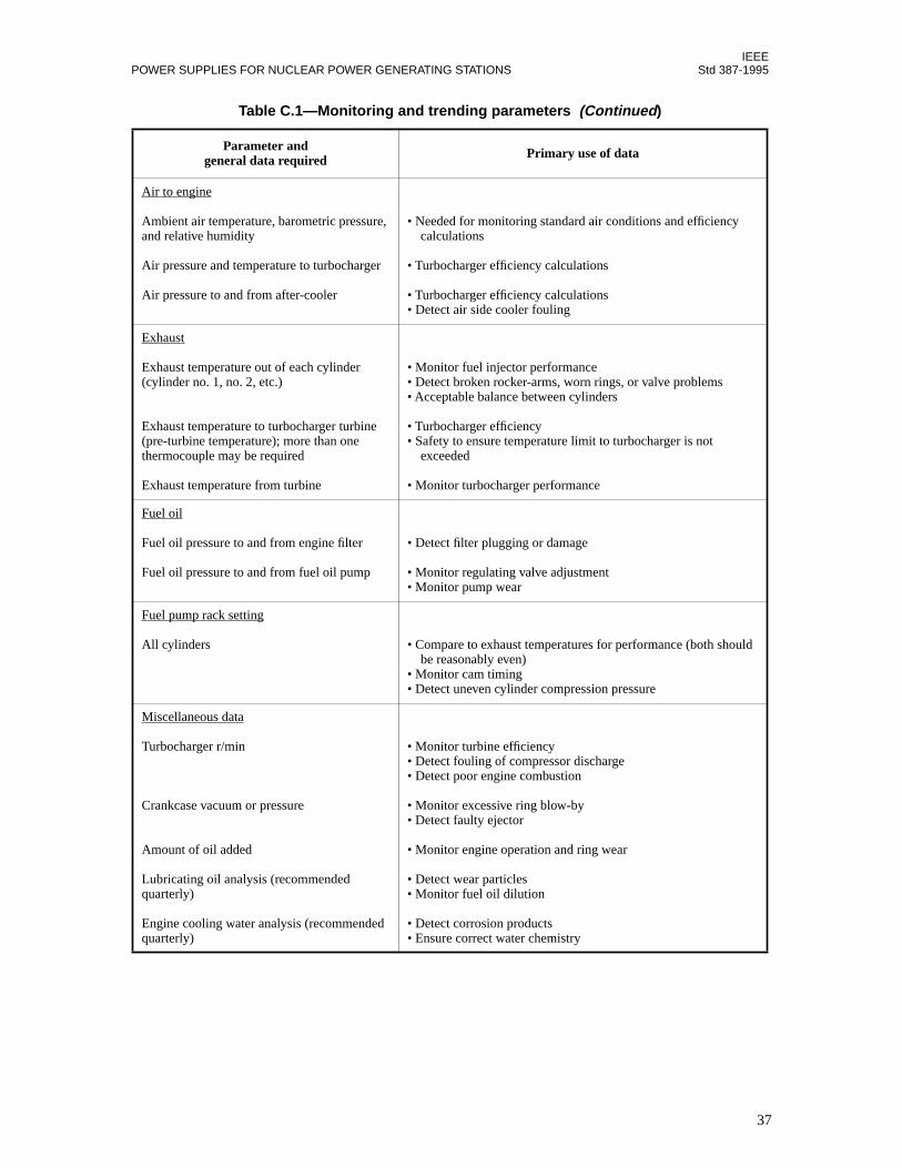
IEEEPOWER SUPPLIES FOR NUCLEAR POWER GENERATING STATIONS Std 387-1995
Air to engine
Ambient air temperature, barometric pressure, and relative humidity
Air pressure and temperature to turbocharger
Air pressure to and from after-cooler
• Needed for monitoring standard air conditions and efficiency calculations
• Turbocharger efficiency calculations
• Turbocharger efficiency calculations• Detect air side cooler fouling
Exhaust
Exhaust temperature out of each cylinder(cylinder no. 1, no. 2, etc.)
Exhaust temperature to turbocharger turbine (pre-turbine temperature); more than one thermocouple may be required
Exhaust temperature from turbine
• Monitor fuel injector performance• Detect broken rocker-arms, worn rings, or valve problems• Acceptable balance between cylinders
• Turbocharger efficiency• Safety to ensure temperature limit to turbocharger is not exceeded
• Monitor turbocharger performance
Fuel oil
Fuel oil pressure to and from engine filter
Fuel oil pressure to and from fuel oil pump
• Detect filter plugging or damage
• Monitor regulating valve adjustment• Monitor pump wear
Fuel pump rack setting
All cylinders • Compare to exhaust temperatures for performance (both should be reasonably even)• Monitor cam timing• Detect uneven cylinder compression pressure
Miscellaneous data
Turbocharger r/min
Crankcase vacuum or pressure
Amount of oil added
Lubricating oil analysis (recommended quarterly)
Engine cooling water analysis (recommended quarterly)
• Monitor turbine efficiency• Detect fouling of compressor discharge• Detect poor engine combustion
• Monitor excessive ring blow-by• Detect faulty ejector
• Monitor engine operation and ring wear
• Detect wear particles• Monitor fuel oil dilution
• Detect corrosion products• Ensure correct water chemistry
Table C.1—Monitoring and trending parameters (Continued)
Parameter andgeneral data required Primary use of data
37

IEEEStd 387-1995 IEEE STANDARD CRITERIA FOR DIESEL-GENERATOR UNITS APPLIED AS STANDBY
38
IEEEPOWER SUPPLIES FOR NUCLEAR POWER GENERATING STATIONS Std 387-1995
Annex D
(informative)
Diesel-generator unit reliability program elements
D.1 General
Nuclear power generating stations are developing formal reliability programs for the installed diesel-generator units. Guidelines for an effective program have been developed and published by the NuclearManagement and Resources Council (NUMARC), now known as the Nuclear Energy Institute (NEI). Thisdescription is intended to highlight the technical points and major diesel-generator unit reliability programelements that should be universally applicable. Station specific administrative details and supporting formalprocedures should be developed to amplify these major reliability elements.
D.2 Major reliability program elements
The principal elements of an effective diesel-generator unit reliability program are the following:
a) Overall diesel-generator unit reliability program planb) Defined management and technical responsibilities for each program elementc) Plant-specific surveillance and monitoring pland) Plant record and data management system designed for easy data retrievale) Defined maintenance program with a reliability focusf) Procedures for failure identification, root cause analysis, and future failure preventiong) Procedures and criteria for problem closeout and follow-up
D.3 Element discussion
The principal element of a reliability program is an overall plan. The plan should specifically address allother plan elements by addressing their appropriate importance in an integrated manner. Plan procedures,surveillance, training, monitoring and trending, and failure resolution documentation should all be a part ofthe reliability plan.The management and technical responsibilities for each program element should beestablished in written procedures. The plan should address training of qualified personnel in detailed engineand governor maintenance procedures similar to that offered by manufacturers of this equipment. An overallresponsibility for diesel-generator unit related matters and coordination may give the best results.
The periodic testing and monitoring element should address reliability by use of monthly system operationintended to determine the condition of important engine/generator parameters. These typically shouldconsist of oil, water, and gas temperatures and pressures in the various engine subsystems during operationand while generating power equal to the plant emergency power requirements. Daily, weekly, monthly, andquarterly surveillance should also be specified. Engine and generator operating parameters and surveillancesassociated with degraded performance and aging should be trended, where such trending could detectincipient failures and permit corrective maintenance before the actual failure occurs.
A record and data management system, designed for easy data retrieval, should be available for use by plantpersonnel. Diesel-generator unit records are important and should support the other program elements.Measures should be taken to safely store these records and prevent their loss. A computer-managed system isrecommended to reduce costs and improve access to the data.
39

IEEEStd 387-1995 IEEE STANDARD CRITERIA FOR DIESEL-GENERATOR UNITS APPLIED AS STANDBY
The maintenance program should have a reliability improvement intent. In some cases, past practices ofcertain preventive maintenance procedures and routine disassembly for inspection purposes have beenshown to have negative results on reliability. A good maintenance program should, over time, eliminatethose procedures. Systems with higher failure rates, such as the instrument and control system, shouldreceive additional maintenance effort for improved reliability. Diesel-generator unit system modificationsmay be included in the plan under the maintenance responsibilities. Reliability considerations should be apart of the modification review process.
Failure identification, analysis for failure root cause, and correction should be defined in procedures. Eachanalysis should have the intent to reduce failures by identifying a corrective action to prevent future failures.For some failures of an intermittent nature, it may be impossible to assign an exact root cause.
Problem closeout should include follow-up to ensure that the problem has been corrected and that relatedproblems are not recurring. Failures with a recurring root cause show that corrective actions taken in the pastwere not correct and a new analysis should be performed with a more appropriate corrective action as theexpected result. The plant records should be reviewed for each analysis and problem closeout to ensure thatrecurring failures are eliminated.
40