ieee1284
DESCRIPTION
Standard for aTransport IndependentPrinter System InterfaceTRANSCRIPT

Standard for aTransport Independent
Printer System Interface
IEEE P1284.1DRAFT STANDARD
1.0V1
October 20, 1995
02:01 PM
Important: This is an unapproved IEEE Standards Draft, subject to change. Permission is hereby granted forIEEE Standards Committee participants to reproduce this document for purposes of IEEE standardizationactivities, including balloting and coordination. If this document is to be submitted to ISO or IEC, notificationshall be given to the IEEE Copyright Administrator. Permission is also granted for member bodies and technicalcommittees of ISO and IEC to reproduce this document for purposes of developing a national position. Otherentities seeking permission to reproduce this document for these or other uses, must contact the IEEE StandardsDepartment for the appropriate license. Use of the information contained in this unapproved draft is at your ownrisk.
IEEE Standards DepartmentCopyright and Permissions
445 Hoes Lane, P.O. Box 1331Piscataway, NJ 08855-1331
USA
Copyright © 1995 byTHE INSTITUTE OF ELECTRICAL AND ELECTRONIC ENGINEERS, INC.345 East 47th Street, New York, NY 10017-2394, USAAll rights reserved.

IEEE P1284.1 Draft Standard 1.0v1
10/20/95 2:01 PMThis is an unapproved IEEE Standards Draft, subject to change.
Page ii Copyright © 1995 IEEE. All rights reserved.

IEEE P1284.1 Draft Standard 1.0v1
10/20/95 2:01 PMThis is an unapproved IEEE Standards Draft, subject to change.
Copyright © 1995 IEEE. All rights reserved. Page iii
Table of Contents1. About This Specification .............................................................................................................................. 9
1.1 Scope.......................................................................................................................................... 9
1.2 Purpose....................................................................................................................................... 9
1.3 Introduction................................................................................................................................ 9
1.4 The Current Situation ................................................................................................................. 10
2. Glossary........................................................................................................................................................ 11
3. Software model............................................................................................................................................. 17
3.1 IEEE 1284.1 printer model ......................................................................................................... 17
3.2 Printer job data flow ................................................................................................................... 19
3.2.1 Session and Job concepts ....................................................................................... 19
3.2.2 Session Data Flow Model....................................................................................... 20
3.2.3 Job Data Flow Model............................................................................................. 20
4. The Command/Reply Structure..................................................................................................................... 23
4.1 General Topics ........................................................................................................................... 23
4.1.1 Commands............................................................................................................. 23
4.1.2 Responses .............................................................................................................. 23
4.1.3 Alerts..................................................................................................................... 23
4.1.4 General Flow ......................................................................................................... 23
4.1.5 Guidelines for Manufacturer Unique Commands.................................................... 24
4.2 The Structure.............................................................................................................................. 24
4.2.1 Basic Packet Structure ........................................................................................... 24
4.2.2 Definition of Command Fields............................................................................... 24
4.2.3 General Printer to Host Protocol Considerations .................................................... 25
4.2.4 Definition of Response Fields ................................................................................ 26
5. Command Set ............................................................................................................................................... 29
5.1 Overview.................................................................................................................................... 29
5.2 Request Device Characteristics (RDC) ....................................................................................... 29
5.2.1 Overview ............................................................................................................... 29
5.2.2 Request Summary .................................................................................................. 30
5.2.3 Request Input Characteristics................................................................................. 36
5.2.4 Request Output Characteristics .............................................................................. 43
5.2.5 Request Option Characteristics .............................................................................. 45
5.3 Request Interpreter Characteristics (RIC) ................................................................................... 46
5.3.1 Overview ............................................................................................................... 46
5.3.2 Summary Information ............................................................................................ 46

IEEE P1284.1 Draft Standard 1.0v1
10/20/95 2:01 PMThis is an unapproved IEEE Standards Draft, subject to change.
Page iv Copyright © 1995 IEEE. All rights reserved.
5.3.3 Font Details ........................................................................................................... 49
5.3.4 Input Characteristics .............................................................................................. 52
5.3.5 Output Characteristics............................................................................................ 54
5.4 Job Control (JC) ......................................................................................................................... 55
5.4.1 Controlling the process of data............................................................................... 55
5.4.2 Job Control Usage.................................................................................................. 57
5.4.3 JC subcommands ................................................................................................... 57
5.4.4 Start Job................................................................................................................. 58
5.4.5 End Job.................................................................................................................. 60
5.4.6 Query Job(s) Completed......................................................................................... 61
5.4.7 Query Job(s) Queued or Active .............................................................................. 63
5.4.8 Start Session .......................................................................................................... 64
5.4.9 End Session ........................................................................................................... 65
5.4.10 Query Session(s) Queued or Active...................................................................... 66
5.4.11 Change Session Priority Subcommand ................................................................. 66
5.4.12 Delete Session Subcommand................................................................................ 67
5.4.13 Resume Suspended Job ........................................................................................ 68
5.5 Request Device Status (RDS) ..................................................................................................... 68
5.5.1 Overview ............................................................................................................... 68
5.5.2 Request Status Summary........................................................................................ 69
5.5.3 Request Input Status .............................................................................................. 71
5.5.4 Request Output Status............................................................................................ 73
5.5.5 Request Input Alert ................................................................................................ 75
5.5.6 Request Output Alert ............................................................................................. 75
5.5.7 Request Jam Alert.................................................................................................. 76
5.5.8 Request Operator Intervention Required Alert ....................................................... 77
5.5.9 Request Warnings .................................................................................................. 79
5.5.10 Device Service Required Alerts ........................................................................... 80
5.5.11 Request Configuration Change Alert.................................................................... 81
5.5.12 Supplies Alerts..................................................................................................... 83
5.5.13 Request Printer Statistics...................................................................................... 85
5.5.14 Request Supplies Status ....................................................................................... 86
5.6 Printer Configuration Control (PCC) .......................................................................................... 87
5.6.1 Overview ............................................................................................................... 87
5.6.2 Read Current Printer Configuration........................................................................ 87
5.6.3 Reset Printer .......................................................................................................... 88

IEEE P1284.1 Draft Standard 1.0v1
10/20/95 2:01 PMThis is an unapproved IEEE Standards Draft, subject to change.
Copyright © 1995 IEEE. All rights reserved. Page v
5.6.4 Select Device Status Alerts .................................................................................... 89
5.6.5 Data Loop-Back..................................................................................................... 89
5.6.6 Select Host Packet Size.......................................................................................... 90
5.6.7 Reset Host Controlled Counter............................................................................... 90
5.6.8 Select Unsolicited Interpreter Messages................................................................. 90
5.6.9 Read Interpreter Messages Selected ....................................................................... 90
5.6.10 Select Job Alerts .................................................................................................. 91
5.6.11 Read Job Alerts Selected...................................................................................... 91
5.6.12 Set Printer ID ....................................................................................................... 92
5.6.13 Read Printer ID .................................................................................................... 92
5.6.14 Enable Common Printer MIB Alert...................................................................... 92
5.6.15 Disable Common Printer MIB Alert..................................................................... 93
5.7 Request Logical Unit Characteristics (RLUC) ............................................................................ 93
5.7.1 Overview ............................................................................................................... 93
5.7.2 Summary Information ............................................................................................ 93
5.8 Printer Variable Commands (PVC)............................................................................................. 94
5.8.1 Overview ............................................................................................................... 94
5.8.2 Get Printer Variable ............................................................................................... 94
5.8.3 Set Printer Variable................................................................................................ 95
5.8.4 Get Next Printer Variable....................................................................................... 96
5.9 Remote Operator Panel (ROP).................................................................................................... 97
5.9.1 Overview ............................................................................................................... 97
5.9.2 Request Summary .................................................................................................. 97
5.9.3 Request Object Characteristics............................................................................... 99
5.9.4 Read Object ........................................................................................................... 100
5.9.5 Select Alerts .......................................................................................................... 101
5.9.6 Read Alerts Selected.............................................................................................. 101
5.9.7 Acquire Panel Control............................................................................................ 101
5.9.8 Relinquish Panel Control ....................................................................................... 102
5.9.9 Control Panel Object.............................................................................................. 102
5.9.10 Read Panel Variables ........................................................................................... 103
5.9.11 Set Panel Variables .............................................................................................. 104
5.9.12 Set Panel Password .............................................................................................. 105
5.9.13 Get Color Pallette ................................................................................................ 105
6. Alerts............................................................................................................................................................ 107
6.1 Device Status Alert (DSA).......................................................................................................... 107

IEEE P1284.1 Draft Standard 1.0v1
10/20/95 2:01 PMThis is an unapproved IEEE Standards Draft, subject to change.
Page vi Copyright © 1995 IEEE. All rights reserved.
6.2 Interpreter Message Alerts (IMA) ............................................................................................... 108
6.2.2 Logical Unit Number ............................................................................................. 109
6.2.3 Printer Assigned Job ID ......................................................................................... 109
6.2.4 Page Number of Printer Assigned Job ID ............................................................... 109
6.2.5 Interpreter Flag ...................................................................................................... 109
6.2.6 Interpreter Message Type #n.................................................................................. 109
6.3 Job Control Alerts (JCA) ............................................................................................................ 109
6.3.1 JCA Logical Unit Start........................................................................................... 110
6.3.2 JCA Sheet Complete .............................................................................................. 110
6.3.3 JCA End of Job...................................................................................................... 110
6.3.4 JCA Suspend Processing at Logical Unit Start ....................................................... 111
6.3.5 JCA Suspend Processing at Start of Printing .......................................................... 111
6.3.6 JCA Suspend Processing at Start of Finishing ........................................................ 111
6.3.7 JCA EOJ Accounting Message............................................................................... 112
6.4 Common Printer MIB Alert (CPMA).......................................................................................... 113
6.4.1 CPMA Alert........................................................................................................... 113
6.5 Operator Panel Alert (OPA)........................................................................................................ 113
6.5.1 Operator Panel Alert Message................................................................................ 113
6.5.2 Object State or Contents ........................................................................................ 114
7. Annex (Informative) - Requirements for a Standard Information Mover Protocol with LinkEncapsulation (SIMPLE) .................................................................................................................................. 115
7.1 Background ................................................................................................................................ 115
7.2 Functional Requirements ............................................................................................................ 115
7.2.1 In order delivery of data......................................................................................... 115
7.2.2 Flow control........................................................................................................... 115
7.2.3 Guaranteed delivery / error detection / recovery..................................................... 116
7.2.4 Multiple logical channels ....................................................................................... 116
7.2.5 IEEE 1284 mode independent................................................................................ 116
7.2.6 PDL, application and operating system independent .............................................. 116
7.3 Implementation Goals................................................................................................................. 117
7.3.1 Link independent ................................................................................................... 117
7.3.2 Extensible .............................................................................................................. 117
7.3.3 Low system overhead on both sides of link ............................................................ 117
7.3.4 Backward compatibility ......................................................................................... 117
8. Annex (Informative) - Novell NetWare® Transport Mapping Example ........................................................ 118
8.1 Introduction................................................................................................................................ 118

IEEE P1284.1 Draft Standard 1.0v1
10/20/95 2:01 PMThis is an unapproved IEEE Standards Draft, subject to change.
Copyright © 1995 IEEE. All rights reserved. Page vii
8.2 The IPX Datagram and IEEE 1284.1 .......................................................................................... 118
8.3 Determining IEEE 1284.1 Compatibility .................................................................................... 120
8.4 Device Status Alerts ................................................................................................................... 120
8.5 Polling........................................................................................................................................ 120
9. Annex (Informative) - TCP/IP Transport Mapping Example ......................................................................... 121
9.1 Introduction................................................................................................................................ 121
9.2 IEEE 1284.1 data (TCP) ............................................................................................................. 121
9.3 data block................................................................................................................................... 121
9.4 definitions .................................................................................................................................. 122
9.5 queries & alerts .......................................................................................................................... 122
10. Annex (Informative) - De-multiplexing Alerts ............................................................................................ 125
10.1 Enabling alerts.......................................................................................................................... 125
10.2 Multiple port environment ........................................................................................................ 125
10.3 Multiple node environment....................................................................................................... 125
11. Annex (Informative) - Host Ownership of an IEEE 1284.1 Printer .............................................................. 127
11.1 Smart “Print Server” ................................................................................................................. 127
11.2 Auto-Configurable Device Driver............................................................................................. 127
11.3 Operating System Imbedded Support........................................................................................ 127


IEEE P1284.1 Draft Standard 1.0v1
10/20/95 2:01 PMThis is an unapproved IEEE Standards Draft, subject to change.
Copyright © 1995 IEEE. All rights reserved. Page 9
1. About This Specification
1.1 Scope
This project will develop a standard protocol for the control of printers. This protocol will be independent of theunderlying data stream or page description language used to create the page. This protocol will be usable by allclasses of printers. This project is limited to management and control of printers and will not include managementof printing system or subsystems.
1.2 Purpose
There is currently no defined, independent standard for controlling printers. Each vendor builds some control intothe underlying page description language or data stream. Without an independent, openly defined protocol,applications and operating systems cannot automatically determine the type of printer being addressed. Thisprotocol will provide a minimum implementation subset which will allow automatic identification andconfiguration of printers and vendor extensibility to provide for growth and product differentiation.
1.3 Introduction
This specification defines a standard protocol for communications between a host and printer. Its intent is toprovide standard methodology for software developers, computer vendors, and printer manufacturers that facilitatethe orderly exchange of information between printers and host computers. The specification defines a minimumset of functions that permit meaningful data exchange. Thus, this standard establishes a foundation upon whichcompatible applications, computers, and printers can be developed, without compromising a particularorganization's desire for design innovation. The following objectives accompany this specification:
1. Simplify the printer driver development process by defining a standard set of command/response transactionsbetween the host computer and printer.
2. Accelerate the development of communicating printers by providing a robust protocol that can beimplemented in phases ranging from basic to extended functionality.
3. Ease customers' printing problems (especially over networks) by accelerating the availability ofcommunicating printers and compatible host software.
4. Assist software developers in minimizing time to market by establishing a base set of functions that insure aminimum level of communications between the host and printer.
5. Facilitate the creation of powerful network print management software by defining transactions that workacross a wide range of printers.
6. Enable the creation of standard control/communications firmware that can be included in many peripheraldevices.
7. Create a standard methodology for host and printer communications that is independent of the transportmechanism used between devices.
8. Enhance the management of printers in networks by providing a mechanism for printers to readily providetheir status and configuration to the host application.
9. Permit design innovation by providing flexibility within the specification for printer manufacturers to includeextensions to the original set of guidelines.
10. Insure cross-platform host-to-printer communications by creating an operating system-independent set ofguidelines.

IEEE P1284.1 Draft Standard 1.0v1
10/20/95 2:01 PMThis is an unapproved IEEE Standards Draft, subject to change.
Page 10 Copyright © 1995 IEEE. All rights reserved.
11. The resultant protocol is PDL independent with the capability of a printer to support multiple PDLs, all activeat the same time, if desired.
1.4 The Current Situation
Local area networks are increasingly becoming the most popular means of interconnecting devices within acorporation. With costs per connection coming down, this trend shows no sign of abating. As networks growlarger, more computers and printers will be interconnected. Any weaknesses in network printing will only bemagnified as more devices are made to communicate.
The absence of feedback from existing printers causes many problems in today's network environment. Forexample, a user could be submitting a job to a remote printer. If that printer is low on toner, most printers todaydo not have the capability to inform users about this condition. Additionally, if the job is large, the user riskshaving to wait until the job is finished before finding out that the output is incorrect. The resulting waste of paper,toner, and time could be significant when calculated over a period of time on a large network.
Standardized feedback information from a printer would solve this problem. By the use of this standard, when aprinter recognizes a condition that would prevent it from accurately printing a job, it can send a standardizedmessage to a host computer that is monitoring network printing. Upon receipt of this message, the host could thensend a message to the user who submitted the job informing him of the error condition. The user could thenredirect a job to a more appropriate printer or undertake action to correct the defect at the target printer. Whenprojected over a period of time and a large number of network users, the resulting monetary savings could besubstantial.
The example shown above is just one of many error conditions that could occur when printing either on astandalone computer or over a network. By using this standard format for exchanging information between theprinter and host, software vendors, network suppliers, and printer manufacturers will now be able to greatlyimprove the efficiency of network printing.

IEEE P1284.1 Draft Standard 1.0v1
10/20/95 2:01 PMThis is an unapproved IEEE Standards Draft, subject to change.
Copyright © 1995 IEEE. All rights reserved. Page 11
2. Glossary
This Glossary defines certain terms used in this specification which may not be generally familiar or which maybe used with a very specific meaning. These definitions are not intended to be absolute but rather to give thesense of the terms as used in this specification.
ASCII A text string of some arbitrary length. The text string may contain non-printablecharacters. The length must be stated in another field. The encoding is typicallyISO 8859-1, but is specified by the Printer Language field in a RDC-RSresponse.
bit A single binary integer. A set bit represents to a binary '1'. A cleared bitrepresents a binary '0'.
big endian Implies that bytes in a word and words in a dword are transmitted mostsignificant byte or word first in a serial stream of bytes.
bbyte bit encoded byte.
bit encoded byte A byte with a definition for each bit.
bit encoded word A word with a definition for each bit.
bword bit encoded word.
byte an entity composed of 8 bits, used to define a unit element of memory ortransmitted data. It is capable of describing integers in the decimal range -128to 127.
command a message from the host directed to the printer that may or may not includeprint data.
connection A parallel interface state that is outside the scope of this specification and is notdefined herein. This state is indicative of the state of the physical or logicalconnection between a host and the printer. Only in this state can data betransferred between a host and the printer.
console language The human language in which information is to be displayed on local orremote consoles.
deprecated Supported by predecessors to this standard but no longer used.
DMI Desktop Management Interface. A facility, normally host resident, for handlingand translating defined interfaces for component information, eventinformation, stored Management Information Format (MIF) structures andmanagement information. In this context, a component is an integral device orproduct, such as a printer; and event is an asynchronous alert or trap. Themanagement information is used by an application such as a user managementprogram; or may be converted for use by a network management facility. TheDMI is controlled by the DMTF.
DMTF Desktop Management Task Force. An association of software developers, hostcomputer and peripheral device manufacturers which promulgate a platformindependent interface standard for the management of desktop computers andthe peripheral devices attached to such computers. In addition to defining theinterfaces between components, the host based service layer and managementapplications, the association supports the development of consistentmanagement information formats (MIF) structures which define thesignificant manageable and status attributes of various components

IEEE P1284.1 Draft Standard 1.0v1
10/20/95 2:01 PMThis is an unapproved IEEE Standards Draft, subject to change.
Page 12 Copyright © 1995 IEEE. All rights reserved.
incorporated into desktop computers.
duplex For purposes of this specification, duplex printing is the process of creatingimages or impressions on both sides of the printing media.
document An encoded, electronically transmittable image, set of images, or imagerelated information, which is handled by the PICU.
double word A double word is a field composed of two words. In a message, the mostsignificant word is transmitted/received first. It is capable of describingintegers in the decimal range -2,147,483,648 to 2,147,483,647.
dword Double word.
facsimile A process by which textual or pictorial images are communicated typicallybut not exclusively over telephone lines. The images may be coded in raster orcompressed raster format (such as CCITT group 3) or in a page descriptionlanguage such as Adobe PostScript. Facsimile typically operates down to thephysical link level and includes protocols providing control and addressingmechanisms specific to the media being used. This is distinguished from theprocess of communicating similarly encoded images over local or wide areanetworks. However, both may be considered implementations of remoteprinting.
feed direction On most printers, the medium is moved through the marking engine. Thedirection that the medium is moved is called the feed direction. For a printerin which the medium is not moved, the feed direction may be considered asalong the Y axis. The across feed direction is the direction orthogonal to thefeed direction; it is also called the cross-feed or scan direction on someprinters.
finishing An operation or group of operations performed on the printed media after itemerges from the printer output mechanism. Finishing includes operationssuch as stapling (stitching), punching, binding, folding, cutting, etc.; they mayor may not be considered part of the printing process. Note that operations ofcollating and sorting are normally considered printer output functions ratherthan finishing.
host Whatever is driving (i.e. providing commands/data) to the printer (e.g.., aworkstation, a print server, or spooler )
IETF Internet Engineering Task Force, a volunteer group that sets technicalstandards for inter-networking.
impressions An impression is the process of marking the media. A single sided, one colorprinter requiring one pass per sheet would produce one impression per sheet. Asimilar printer printing duplex would produce two impressions per sheet. Atwo pass printer providing a base color and a highlight color would producetwo impressions per side, etc.
interpreter language The printer machine language, or page description language, by whichinformation to be imaged or to be used in imaging is coded. Since printerssometimes emulate original implementations of these languages, interpreterlanguages are sometimes called emulations.
interpreter A functional entity which translates one or more printer control or pagedescription languages into a form suitable for the marking engine.
job That entity originated or initiated by a user, which is handled by the PICU. Ajob need not result in the imaging of information on media.

IEEE P1284.1 Draft Standard 1.0v1
10/20/95 2:01 PMThis is an unapproved IEEE Standards Draft, subject to change.
Copyright © 1995 IEEE. All rights reserved. Page 13
KB A kilobyte; 1,024 bytes.
legacy application or device A printing application or device in existence prior to the existence of thisspecification. Hence, such device is unaware of the protocol defined herein.
link The physical or logical connection between a host and a printer.
logical unit An addressable, functional group. In the case of a printer, scanner or facsimileit is a functional group concerned with the storage, acquisition and/orprocessing of a textual and/or pictorial image. A printer may have one or moreinterpreters. The design of a particular printer determines if these interpretersare capable of concurrent operation.
LU Logical unit.
marking engine A set of electrical and mechanical components that moves the print media andmarks that media. In some implementations, a facsimile transmission functionis considered to be a marking engine.
message A logical grouping of one or more packets sent either from host to printer (acommand message) or from printer to host (a response message).
message length Although messages can be of any length up to 65,539 bytes, the packet sizeshould be selected for effective transmissions over the physical link withoutrequiring disassembly and re-assembly. For connections through a network, thepacket size of that network would generally be the most efficient.
MIB Management Information Base. A SNMP compatible data structure thatdefines the functional groups and management objects of a unit or system. Thisstandard includes a mechanism whereby the object values can be obtainedfrom the printer by a device acting as the SNMP agent for the printer.
MIF Management Information Format. A DMI compatible data structure thatdefines the functional groups and management objects of a unit or system.
multiple-packet errorrejection
Error handling and rejection notification occurs on a message-by-messagebasis. This specification assumes the existence of a reliable transport layerprotocol. Error detection and packet sequencing is a transport layer functionand is beyond the scope of this specification.
NPAP Network Printing Alliance Protocol . A transport independent printing protocolfrom which this standard has been derived.
NULL A byte with all bits set to zero.
octet An eight-bit data entity (byte)
object identifier In general, the object identifier is a unique representation (name) of amanageable object defined in a MIB.
OID Object identifier.
packet The basic message element used by this standard; a structured field, having astart byte, a two byte length field (the first two bytes), a flag byte, a commandbyte, followed by the sub-command and/or data fields.
page A page is a function of the document formatting rather than the printingprocess. A "four-up" single color printing will typically have four pages perimpression.
page description language An interpreter.

IEEE P1284.1 Draft Standard 1.0v1
10/20/95 2:01 PMThis is an unapproved IEEE Standards Draft, subject to change.
Page 14 Copyright © 1995 IEEE. All rights reserved.
PDL Page description language.
PICU Printer interface control unit.
print engine That set of electrical and mechanical mechanisms that move the print media orpaper and marks that paper.
print media That consumable upon which the marking engine marks so as to form a textand/or pictorial image; typically paper.
printer An intelligent device which includes, as a primary function, the ability toconvert an electrically transmitted or stored image into a physical imageformed by colorant on some medium (such as paper).
printer interface controlunit
The set of electronics that interfaces external communications ports, commonperipheral interfaces (such as font cards or disk drives), the logical units, andthe marking engine. It is the function of the PICU to coordinate and sequenceall the functions and operations of the printer.
printer language The human language used for the ASCII strings within all command andresponse messages, other than those to be printed or those to be displayed onthe local or remote consoles. (e.g., English, French, German)
printing That set of operations implemented by the printer which results in an imagerendered as marks on the selected media.
reply or response Messages from the printer to the host.
RFC Request for Comments as defined by the IETF.
session A printer state that allows the logical grouping of one or more jobs into asequential, reference-able collection.
sheet A sheet is a cut piece of print media, such as a sheet of paper.
SNMP Simple Network Management Protocol. A protocol used for the managementof network nodes and devices, used extensively on internet and other networks.The protocol provides for the communication of status and setup informationbetween a management console and a managed device using values of objectsdefined in the MIB for the managed object.
space character A byte (hex 20) used in text strings that represents a space.
start of packet byte A single byte (hex A5, decimal 165) that is used by both the printer device andthe host to quickly determine whether or not they are synchronized.
TIPSI Transport Independent Printer System Interface. An abbreviation of the title ofthis specification.
transport or transport layer The middle layer in the ISO seven layer open system communicationsreference model, and the boundary between the communication subnet layers (Physical, Data Link and Network) and the host process layers (Session,Presentation and Application). In defining this specification as an transportindependent interface, the interface is considered as operating at the Session,Presentation and Application levels and is independent of the mechanism bywhich the interface information is communicated.
udword unsigned dword.
unsigned byte A byte that represents positive integers in the decimal range 0 - 255.
unsigned dword A dword that represents positive integers in the decimal range 0 -

IEEE P1284.1 Draft Standard 1.0v1
10/20/95 2:01 PMThis is an unapproved IEEE Standards Draft, subject to change.
Copyright © 1995 IEEE. All rights reserved. Page 15
4,294,967,295
unsigned word A word that represents positive integers in the decimal range 0 - 65535.
uword Unsigned word.
word A word is a field composed of two 8-bit bytes. In a byte serial message, themost significant byte is transmitted/received first, (big endian). It is capable ofdescribing integers in the decimal range -32,768 to 32,767.


IEEE P1284.1 Draft Standard 1.0v1
10/20/95 2:01 PMThis is an unapproved IEEE Standards Draft, subject to change.
Copyright © 1995 IEEE. All rights reserved. Page 17
3. Software model
3.1 IEEE 1284.1 printer model
A printer can be thought of as a minimum of three logical entities: The Print Engine, Printer Interface ControlUnit (PICU), and one or more LUs (one of which is an interpreter). Figure 1 shows a logical model of the IEEE1284.1 printer.
It is important to note that while an interpreter is a logical unit (LU) the converse is not always true. A LU can beanother logically separate device in the printer such as a facsimile engine or document scanner.
The management of producing a printed document is complex. The task can be divided into two overlappingpieces, the management of printing and the management of the printer. Printing encompasses the entire process ofproducing a printed document: generation of the file to be printed, selection of a printer, choosing printingproperties, routing, queuing, resource management, scheduling, and final printing including notification of theuser. This standard enables communications of printer status and attributes that, when used by applications,greatly enhance both the management of printing and of the printer.
In this standard commands have been defined that allow the manipulation of manageable objects that arecontained in a printer and are capable of being referenced using an OID such as those print objects defined in theIETF Printer MIB (RFC1759). Job delivery is outside the scope of RFC1759 as it has chosen only to cover themanagement of the printer itself. In doing so, RFC1759’s printer model differs from the one presented in figure 1.The RFC1759 model is basically an exploded view of the print engine and control blocks used by this standard.

IEEE P1284.1 Draft Standard 1.0v1
10/20/95 2:01 PMThis is an unapproved IEEE Standards Draft, subject to change.
Page 18 Copyright © 1995 IEEE. All rights reserved.
Figure 1: printer model
The function of this standard’s protocol is to provide a means of returning configuration and status information ina manner that is independent of the printer’s physical connection, imaging technology, or embodied LU(s). In thismodel, the printer is intended to be managed by some intermediate system element external to the printer. Theprotocol provides a method for:
• retrieving traditionally static information such as the number and type of paper input and output trays,imaging resolution and speed, interpreter capabilities and their relationship to the print mechanism, etc.
• returning real-time status information related to the print mechanism that is independent of the LUs such aspaper and printing supplies levels.
• a separate, logical, out of band communication channel for exchanging commands and responses. This out ofband channel is key to the effective management of the printer while page processing is being done.
• selection or activation of a LU via host control.

IEEE P1284.1 Draft Standard 1.0v1
10/20/95 2:01 PMThis is an unapproved IEEE Standards Draft, subject to change.
Copyright © 1995 IEEE. All rights reserved. Page 19
• job separation.
• reporting job statistics independent of the LU.
The protocol has been designed to be link independent. The only requirement is that the link must be capable ofbi-directional data transmission. Numerous methods and media exist today to facilitate this transport ofinformation. Included are various LAN protocols (802.2, TCP/IP, etc.), asynchronous serial communications, andmore recently the bi-directional parallel port defined by IEEE Std 1284-1994, "Standard Signaling Method for Bi-directional Parallel Peripheral Interface for Personal Computers."
3.2 Printer job data flow
A generalized model of the data flow for a job is shown in figure 3. The model is used to visualize the sequence ofevents for printing and for the identification of the position of a particular job in the printing process. Data isreceived by the protocol processing layer from the data link and physical layer. The model assumes that theprinter is a simple buffered device and handles print data via a simple, single threaded queue.
The first action taken by the printer is to determine if the received data is directed to a LU or is a command. Thisdecision is facilitated by examining the flag byte in the packet header. If the data packet contains a command it isplaced in a command buffer. With the exception of the Start Session, Start Job, End Job, and End Sessioncommands, all commands are acted on immediately. The size of the command buffer is dependent on the specificprinter implementation.
When the data is LU destined, the higher order bit (bit 7) of the LU address is used to determine if the data is to beput into the job buffer or sent immediately to the active LU, bypassing the buffer.
As data is removed from the job buffer the printer activates the appropriate LU. It is important to note that one ormore LUs may be active at any point in time depending on printer implementation. When the LU finishesprocessing or reaches an appropriate point, the printer control system then allocates the print engine to the LU. Forthis discussion, it is assumed that a printer has only one print engine available for use, even if there are multipleLUs processing data simultaneously. Once the document has been printed any available and requested finishingoperations are performed. Upon completion of any document finishing, the document is marked is delivered andthe end of job signaled to the host if requested.
The preceding explanation is a highly simplified and sequential model of the printing process. In an actualimplementation most of the steps of starting an LU, processing data, printing data and finishing can beoverlapped. The start of LU processing may imply that printing and or finishing resources are allocatedsimultaneously. It is not required that one step in the printing process be completed before the next is started.
3.2.1 Session and Job concepts
Within the IEEE 1284.1 framework the basic logical grouping of data is the job. Jobs are delineated in the datastream by the Start Job and End Job commands. The Start Job command prompts the printer to initialize thegraphic engine and reset accounting statistics. The End Job command instructs the printer to log the accountingstatistics, and release any non-persistent job-related resources.
A session allows the logical grouping of one or more jobs into a sequential, reference-able collection. Empty jobsand empty sessions are valid. Sessions are delineated in the data stream by the Start Session and End Sessioncommands. The Start Session command is an indicator to the printer that a collection of jobs follows. The printershall use this command to lock port rotation in a multiple link and/or multiple protocol environment. The EndSession command marks the end of the collected data, causes the printer to print and eject any remaining sheets,and allows link rotation.
Because the session commands directly affect link rotation, grouping unrelated jobs in the same session could leadto an unfair allocation of printing resources. Therefore, it is recommended that a session not contain a collectionof unrelated jobs. This recommendation is not an attempt to limit the number of jobs in a session. It is a

IEEE P1284.1 Draft Standard 1.0v1
10/20/95 2:01 PMThis is an unapproved IEEE Standards Draft, subject to change.
Page 20 Copyright © 1995 IEEE. All rights reserved.
recommendation that the host should refrain from concatenating unrelated jobs together in a session tocircumvent link rotation.
3.2.2 Session Data Flow Model
Once a physical or logical connection is established between the host and printer, a start session commandprompts the printer to enter an “in-session” state and return an identifying number for the session. While in this“in-session” state the start job and end job commands are used to delineate related print data. Job statisitics areaccumulated for this delineated data and is provided to one or more hosts.
Figure 2: synchronous model
3.2.3 Job Data Flow Model
The IEEE 1284.1 protocol provides the ability for the host system to coordinate and report on the status of thevarious steps in the printing process so that effective printer and job management can be implemented. The modelis provided as an aid to the visualization of the printing process and does not dictate any particular implementationor control system for a printer. The circled numbers on the job data flow model, figure 3, show status points withthe following brief description as to their meaning.
1. JOB ID ReturnedThis is the first point of synchronization where the printer returns a printer assigned job Identificationnumber to the host after a Start of Job command has been received from the host. The job ID allowsthe host to track a particular job.

IEEE P1284.1 Draft Standard 1.0v1
10/20/95 2:01 PMThis is an unapproved IEEE Standards Draft, subject to change.
Copyright © 1995 IEEE. All rights reserved. Page 21
2. LU Start of ProcessingThis is a synchronization point where the printer has allocated the resources necessary to run a job ona particular LU and is about to begin processing the job. The host has the option of suspending aprint job at this point and interacting with the printer to determine if the appropriate resources areavailable to complete the particular job that is about to be processed by the LU. Checking for aparticular font would be an example of an action that could be taken at this point.
3. Start of PrintingThis is a synchronization point where the printer is about to start physically printing the first page ofthe job. The Host has the option of suspending a print job at this point to interact with the printer todetermine if the appropriate resources are available to complete the printing, such as specific mediainstalled in the printer.
4. Start of FinishingThis is a synchronization point where the host has the option of suspending a print job to interactwith printer to provide detail instructions on final finishing of the document.
5. End of JobThis is the final synchronization point where the print job is complete and job statistics are returnedto the host regarding the print job.

IEEE P1284.1 Draft Standard 1.0v1
10/20/95 2:01 PMThis is an unapproved IEEE Standards Draft, subject to change.
Page 22 Copyright © 1995 IEEE. All rights reserved.
Figure 3: job data flow model

IEEE P1284.1 Draft Standard 1.0v1
10/20/95 2:01 PMThis is an unapproved IEEE Standards Draft, subject to change.
Copyright © 1995 IEEE. All rights reserved. Page 23
4. The Command/Reply Structure
4.1 General Topics
4.1.1 Commands
Commands are host to printer messages instructing the printer to perform some action.
4.1.2 Responses
Responses are printer to host messages sent as the direct result of a command from the host. Every message sentto the printer with the reply required flag (flag bit 4) set shall result in a response from the printer. In the casewhere the printer has no data to return to the host, a short acknowledgment consisting of the original commandwith the flags appropriately updated shall be returned.
4.1.3 Alerts
An unsolicited printer to host message is called an alert. These messages are initiated by exception conditionsdetected in the printer. These events can occur either asynchronously to the command stream (e.g. out oftoner/paper/supplies, cover open, ...) or synchronously to the command stream (e.g. erroneous command). Ineither case, an alert is issued.
The various types of alerts are:
I. Device Status Alerts (DSA) resulting from:
A. Events which occur inside the printer asynchronous to the data stream (i.e. out oftoner/paper/supplies, cover open, job completed, ...)
B. Message errors (i.e. 'invalid logical unit', etc.), when the host did not expect a response(flag bit 4 cleared in message from host to printer)
II. Interpreter Message Alerts (IMA) resulting from interpreter responses to data stream queries
III. Job Control Alerts (JCA) resulting from:
A. A print job completed
B. A print job starting logical unit processing
C. A sheet from a print job being stacked in the output device
IV. Common Printer MIB/MIF Alerts (CPMA) resulting from a critical alert entry (as defined byRFC1759) being added to the printer’s alert table.
4.1.4 General Flow
In general, the host is the master and initiates all exchanges with the printer. With the exception of defined alertsthe printer shall not send an unsolicited response to the host. Solicited responses require that the reply requiredflag is set in the received message.
It is recommended that the host communicate with the printer with the reply required flag set in all commandssent to the printer. In this mode the host sends each message (reply required flag set) to the printer and waits for apositive acknowledgment (printer response) before sending the next message.
When a command with the reply required flag set is received, indicating that the message contains data to bedelivered to a LU, the printer must send a simple response acknowledging that the data was received. Any printerresponse action required as a result of the LU processing data in the message is defined to be unsolicited. Thedecision to return this unsolicited message to the host is governed by a prior command which enabled interpreter

IEEE P1284.1 Draft Standard 1.0v1
10/20/95 2:01 PMThis is an unapproved IEEE Standards Draft, subject to change.
Page 24 Copyright © 1995 IEEE. All rights reserved.
message alerts. If these alerts are enabled, the requested response will be returned to the host as an alert (flag bit 4cleared) from the interpreter (flag bit 6 cleared, command field = interpreter id) directly following an InterpreterMessage Alert message.
4.1.5 Guidelines for Manufacturer Unique Commands
Vendors may define and implement their own unique commands, or "extensions", to the IEEE 1284.1 standard.The vendors who implement their own commands can still be classified as compliant to the standard, but only ifthey have implemented the IEEE 1284.1 commands in accordance to this specification. Support for the uniquecommands is the responsibility of the defining vendor.
Compliant devices shall reject properly structured commands which are not implemented in the device by settingthe flag bits to indicate a data error in the response message sent back to the host. A vendor defining newmanufacturer specific commands shall comply with the architecture of commands/subcommands, packet structure,field definitions, general flow and all other protocols defined in this standard. Vendor compliance shall allowexisting compliant devices to parse and properly reject the extended commands which they do not implement.
4.2 The Structure
4.2.1 Basic Packet Structure
The basic structure for all packets (host to printer and printer to host) is of the form:
Table 1. Basic Packet StructurePacket Header Data Field
Start ofPacketByte
Packet Length Flag Commandor LU #
Data....
4.2.2 Definition of Command Fields
4.2.2.1 Start of Packet Byte (byte 1)
This byte (hex A5) is used by the host to indicate a start of packet. When the printer is in a mode to receive apacket from the host, the first byte received must be a Start of Packet Byte. If this byte is not the first bytereceived, the printer will know immediately that it is out of sync with the host or is not receiving commands ordata compliant with this standard.
4.2.2.2 Packet length (bytes 2 & 3)
Packet length is the number of bytes in this packet not including this length field or the start of packet byte (16 bit,unsigned word). The default "maximum packet size" for commands is 64 bytes. This value shall be used until thehost determines the printer's exact capabilities via a Request Device Status.
4.2.2.3 Flag (byte 4)
The purpose of the flag is to provide a single byte that the printer can examine to obtain control information. Theflag bits are defined as follows:

IEEE P1284.1 Draft Standard 1.0v1
10/20/95 2:01 PMThis is an unapproved IEEE Standards Draft, subject to change.
Copyright © 1995 IEEE. All rights reserved. Page 25
Table 2. Command Flag BitsBit 7 No Operation (NOP)
If this bit is set, it indicates that the host requires the printer to disregard (i.e. not process) this messageregardless of it's contents. If the Reply Required bit is set, the printer is still required to acknowledge thereceipt of this packet (see bit 4).If this bit is cleared, it indicates that the printer is to process the command.
Bit 6 Destination (IEEE 1284.1 Component or LU #)If set, this bit indicates that the message is for the bi-directional software component in the printer and the fifthbyte in the message contains the command op code.If cleared, it indicates the message contains data for an LUwith the fifth byte in the message being the logicalunit number that is to receive the data.
Bit 5 ContinueIf set, this bit indicates that the next packet is a continuation of this message.If cleared, it indicates that this message is 'complete'.
Bit 4 Reply RequiredThe host sets this bit when it requires a response from the printer. If this bit is set, all commands sent from thehost to the printer will be acknowledged by the IEEE 1284.1 component within the printer. If the command isdata for an LU, the printer’s IEEE 1284.1 component will acknowledge the data as being received. The LU willnot respond to the Reply Required flag. If the NOP bit is set, the printer’s IEEE 1284.1 component willacknowledge the data as being received and discarded (byte #5 of the printer response will have the samevalue as byte #5 of the host to printer command).If this bit is cleared, the IEEE 1284.1 component will only respond when errors are detected. The responseswill be sent as unsolicited messages to the host.
Bit 3 UndefinedBit 2 UndefinedBit 1 UndefinedBit 0 Undefined
4.2.2.4 Command byte (byte 5)
The meaning of the command byte is dependent on the state of bit 6 in the flag byte.
If bit 6 is set, this field contains a command for the IEEE 1284.1 command processor. Commands 0-127 (hex 0 to7F) and 240-255 (hex F0-FF) are reserved for IEEE 1284.1 commands and future extensions. Commands 128-239(hex 80-EF) are available for manufacturer or device specific assignment. Assignment of value usage in thisrange is not managed by the IEEE.
If bit 6 is cleared, this field contains the logical unit number destination for this message. A value of 0 is used toselect the default LU. The default LU is defined as the LU compatible with today's machine definition. Forexample, it may be the power on default interpreter that can be overridden by the front panel or the data stream(as in emulation switching).
4.2.2.5 Data bytes (bytes 6, 7, ……)
The meaning of the data bytes are dependent on the state of bit 6 in the flag byte.
If bit 6 is set, this field contains, depending on the command, additional command information and/or data for theIEEE 1284.1 command processor.
If bit 6 is cleared, this field contains data for the logical unit.
4.2.3 General Printer to Host Protocol Considerations
4.2.3.1 Command Error
If a command is received by the printer that is not understood (i.e. undefined), the printer shall set the error flag(bit 7), set bit 3 and clear bit 2 in the packet header of the response. The printer shall perform no other action onthat command other than to flush it from internal buffers. If the host thinks that the printer should have acceptedthe command, it shall re-try the command again.

IEEE P1284.1 Draft Standard 1.0v1
10/20/95 2:01 PMThis is an unapproved IEEE Standards Draft, subject to change.
Page 26 Copyright © 1995 IEEE. All rights reserved.
4.2.3.2 Rejecting a command
Both the host and the printer shall always be able to accept at least one full packet at any time. This packet doesnot necessarily need to be acted upon. A message sent from the host to the printer can be rejected by the printer.To indicate that a given packet has been rejected, the printer shall set the error flag (bit 7) and clear both errortype flags (bits 2 & 3) in the packet header for the reply message. At this point, the host can determine why theprinter could not execute the command by issuing an Request Device Status command, which is always honored.The host can also simply keep sending the command until it is accepted and operated upon.
4.2.3.3 Data Error
If a command is received by the printer that has data that is not understood (i.e. undefined), the printer shall setthe error flag (bit 7), set bit 2 and clear bit 3 in the response sent back to the host. The printer shall perform noother action on that command other than to flush it from internal buffers. If the host thinks that the printer shouldhave accepted the command, it shall re-try the command again.
4.2.4 Definition of Response Fields
4.2.4.1 Start of Packet Byte (byte 1)
This byte is used by the printer to indicate a start of packet. When the host is in a mode to receive a packet fromthe printer, the first byte received shall be a start of packet byte. If this byte is not the first byte received, the hostimmediately know that it is out of sync with the printer.
4.2.4.2 Packet length (bytes 2 & 3)
Packet length is the number of bytes in this packet not including the length field or the start of packet byte (16 bit,unsigned word). The default "maximum packet size" for responses is 64 bytes. This value shall be used until thehost tells the printer otherwise using the Printer Configuration Control command.
4.2.4.3 Flag (byte 4)
The purpose of the flag is to provide a single byte that the host can examine to obtain control information for themessage and a quick view of the printer's status. The flag bits are defined as follows when in response from theprinter:

IEEE P1284.1 Draft Standard 1.0v1
10/20/95 2:01 PMThis is an unapproved IEEE Standards Draft, subject to change.
Copyright © 1995 IEEE. All rights reserved. Page 27
Table 3. Response Flag BitsBit 7 Error
If set, this bit indicates that this response contains error information. This error flag is used to indicate acommand or data error for the command sent to the printer.
Bit 6 Source (IEEE 1284.1 Component or LU #)If set, this bit indicates that the message is from the IEEE 1284.1 command processor in the printer and thecommand field contains the command op code to which the printer is responding.If cleared, it indicates the message contains data from an interpreter and the command field contains the logicalunit number of the specific interpreter that generated the data.
Bit 5 ContinueIf set, this bit indicates that the next packet is a continuation of this message.If cleared, it indicates that this message is 'complete'.
Bit 4 Reply TypeIf this bit is set, it means that this reply was required by the host (i.e. solicited via bit 4 in the message from thehost).When cleared, this bit indicates that this message was not solicited by the host but was caused by an 'error'event at the printer. The error condition is asynchronous and can occur at any time.
Bit 3..2 Command/data check type, encoded as follows:(Note: these bits are valid only when the Error flag (bit 7) is set)Bits 7..3..2 Definition when contained in a message from the printer0xx No errors were detected in the command or data fields100 No errors were detected in the command or data fields, but the command was rejected.101 Data Error110 Command Error111 Reserved
Bit 1..0 Printer Status, These two bits are set to the state of the printer at the time of the reply, independent of whetheror not they were selected (i.e. "armed") by the PCC command. The bits are defined as follows:Bits 1..0 Definition when contained in a message from the printer00 Printer is fine; no alert condition exists01 Printer is still OK, but a condition exists that the operator may want to know about (a warning - low paper,
job end, etc.)10 A condition exists that will prevent further printing, but the operator can fix it (operator intervention required
- out of paper, output bin full, toner low, etc.)11 A condition exists that will prevent further printing and a service/repair call is required to fix it (laser failure,
fuser died, system board error, etc.)
4.2.4.4 Command byte (byte 5)
In a reply, the original op code or interpreter id of the message that caused the reply shall be returned. If themessage was unsolicited from the IEEE 1284.1 command processor (i.e. bit 4 is cleared and bit 6 is set), this fieldshall be set to a value in the range 240-255 (hex F0-FF). Currently 255 (hex FF) is used to identify Device StatusAlerts, 254 (hex FE) is used to identify Interpreter Message Alerts, 253 (hex FD) is used to identify Job ControlAlerts, 252 (hex FC) is used to identify Common Printer MIB Alerts, 251 (hex FB) is used to identify OperatorPanel Alerts, and 240 (hex F0) is reserved for manufacturer specific Device Status Alerts.
4.2.4.5 Response data bytes (bytes 6, 7, ……)
The data bytes shall be interpreted as follows:

IEEE P1284.1 Draft Standard 1.0v1
10/20/95 2:01 PMThis is an unapproved IEEE Standards Draft, subject to change.
Page 28 Copyright © 1995 IEEE. All rights reserved.
Table 4. Interpretation of response data bytes 6, 7, ...Flag Bits 6..4 (Byte #4) Command (Byte #5) Data (Bytes #6 - n)00 Message from an Interpreter LU # Message from the interpreter identified in
byte #501 Required acknowledgment from
IEEE 1284.1 command processorthat data for an interpreter wasreceived & buffered
LU # N/A
10 Alert 240 Manufacturer Specific Alert251 Operator Panel Alert252 Common Printer MIB/MIF Alert253 Job Control Alert254 Interpreter Message Alert255 Device Status Alert
Alert data
11 Required response from bi-directional component
IEEE 1284.1 Command Command Response as defined incommand details for the IEEE 1284.1command indicated by byte #5

IEEE P1284.1 Draft Standard 1.0v1
10/20/95 2:01 PMThis is an unapproved IEEE Standards Draft, subject to change.
Copyright © 1995 IEEE. All rights reserved. Page 29
5. Command Set
5.1 Overview
The defined commands and their hexadecimal equivalents are shown in the following table:
Table 5. CommandsCommand Hexadecimal
EquivalentStatus
Request Device Characteristics 01 currentRequest Interpreter Characteristics 02 currentPrinter Configuration Control 03 currentRequest Device Status 04 currentJob Control 05 currentRequest Logical Unit Characteristics 06 currentControl Packet Rejection 07 deprecatedCommon Printer Variable 08 currentRemote Op Panel 09 current
5.2 Request Device Characteristics (RDC)
5.2.1 Overview
The RDC command provides the host system a method of obtaining information concerning the capabilities andcharacteristics of the printer. The host system would use this information to communicate to the application suchdata as paper size and output capabilities such as sorting. Additionally, the host could use this information forautomatic scheduling and routing applications such as that provided by print servers on a Local Area Network.
Using the RDC command there are various categories of characteristics information that can be obtained. Table 6shows the various categories.
Table 6. RDC CategoriesCategory Description
Summary Provides for an overview of the printer and its capabilities.Input Describes the printing media, paper, input capabilities and features of the printer.Output Describes the printing media, paper, output capabilities and features of the printer.Options Description of the various options contained completely within the printer such as
expanded memory, mass storage or communications functions, etc.
The host queries for the desired information by sending a RDC command with a subcommand in the data fieldthat specifies the category of information desired. The subcommand is a single unsigned byte. The subcommandvalues for the various categories of characteristics are shown in table 7.
Table 7. RDC SubcommandsSubcommand Characteristic Description
00 Summary Information01 Reserved02 Input Characteristics03 Output Characteristics04 Option Characteristics05 to FF Reserved

IEEE P1284.1 Draft Standard 1.0v1
10/20/95 2:01 PMThis is an unapproved IEEE Standards Draft, subject to change.
Page 30 Copyright © 1995 IEEE. All rights reserved.
5.2.2 Request Summary
The RDC Request Summary subcommand (RDC-RS) provides the host system with an overview of thecapabilities of the printer. Using the data returned by the printer, the host knows how to inquire about the detailsof other features such as input and output capabilities. Table 8 shows the format of the command sent to theprinter.
Table 8. RDC-RS CommandBytes Value (hex) Description Notes
5 Request Device Characteristics Packet Header1 00 Request Summary Data Field
After the printer receives the command it will return a summary data packet back to the host as shown in table 9.
Table 9. RDC-RS ResponseBytes Value - Hex Description Notes
5 Request Device Characteristic Packet Header1 00 Request Summary Data Field1 ubyte Major Revision Level of Standard Supported1 ubyte Minor Revision Level of Standard Supported1 ubyte Printer Specific Extension Revision Level Supported1 ubyte Marking Technology1 ubyte Color Capabilities2 uword Number of Monochrome/Color Levels Supported1 bbyte Duplex Capabilities2 uword Maximum Number of Entries in Query Job(s) Completed Queue1 ubyte Speed Units Definition1 ubyte Speed of Printer in Speed Units1 ubyte Length Units Definition2 uword Horizontal Logical Units per Length Unit2 uword Vertical Logical Units per Length Unit1 ubyte Counter Units1 ubyte Reserved4 udword Total Installed Memory (bytes)2 uword Maximum Receive Packet Size2 uword Maximum Number of Outstanding Commands1 00 Deprecated, must be zero1 ubyte Number of Interpreters Supported1 ubyte Number of Inputs Supported1 ubyte Number of Outputs Supported1 ubyte Number of Options Supported1 ubyte Printer Language1 ubyte Length of Product Name (not including this byte)n ASCII Product Name1 ubyte Length of Product Revision ( not including this byte)n ASCII Product Revision1 ubyte Length of Serial Number ( not including this byte)n ASCII Serial Number2 uword Maximum Receive Command Buffer Size
5.2.2.2 Major/Minor Revision Level of Standard Supported
The combination of these two unsigned bytes specify the revision level of the standard supported by this printer.For this standard the major revision level is 2 and the minor revision level is 0.
5.2.2.3 Printer Specific Extension Revision Level Supported
This byte is used by the printer to indicate the presence of additional capabilities that are extensions to thestandard and are unique to this device. If the value of this byte is 0, then there are no extensions to the standard. A

IEEE P1284.1 Draft Standard 1.0v1
10/20/95 2:01 PMThis is an unapproved IEEE Standards Draft, subject to change.
Copyright © 1995 IEEE. All rights reserved. Page 31
value greater than zero indicates the presence of extensions that are specific to that manufacturer of the printer.The significance of the value of this byte, other than 0, is dependent on the manufacturer of the printer.
5.2.2.4 Marking Technology
This unsigned byte defines the type of marking technology used by the printer. The host system can uses this fieldfor scheduling and printer type selection. The values for this field are defined in table 10.
Table 10. RDC-RS Marking Technology CodesValue Description
00 Electrophotographic (LED, Laser, other)01 Impact - Moving Head - Dot Matrix (9 wire, 24 wire)02 Impact - Moving Head - Formed03 Impact - Band04 Ink Jet - aqueous05 Ink Jet - solid06 Pen07 Thermal Transfer08 Thermal Sensitive09 Thermal Diffusion (Sublimation)0A Electrostatic0B Photographic (microfiche, imagesetter, other)0C Ion Deposition0D E-beam0E Typesetter0F Electroerosion10 Ink Jet - other11 Thermal - Other12 - FD ReservedFE OtherFF Unknown
5.2.2.5 Color Capabilities
This unsigned byte defines the color capabilities of the printer. The host system can use this field for schedulingand printer type selection. This field has encoded meanings as defined by table 11.
Table 11. RDC-RS Color Capabilities CodesValue Description
00 Monochrome01 Spot Color02 3-primary (CMY) Color03 4-primary (CMYK) Color0E - FD ReservedFE OtherFF Unknown
5.2.2.6 Monochrome/Color Levels Supported
This unsigned word defines the number of color or monochrome levels that are supported by the printer.
For monochrome printers, this field contains the number of distinct gray scale levels supported at the printer'smaximum resolution, not including "white" or "unmarked". For example, a black/white printer with no gray-scalecapability should report 1 in this field.
For spot-color printers, this field contains the number of spot colors supported, not including "white" or"unmarked". For example, a black/white/red printer should report 2 in this field.
For 3-primary and 4-primary color printers, this field contains the maximum number of distinct levels, notincluding "white" or "unmarked", of any one primary at the printer's maximum resolution. Note that the number

IEEE P1284.1 Draft Standard 1.0v1
10/20/95 2:01 PMThis is an unapproved IEEE Standards Draft, subject to change.
Page 32 Copyright © 1995 IEEE. All rights reserved.
of distinct colors achievable by combining primaries may be significantly less than the product of the number oflevels in each primary.
5.2.2.7 Duplex Capabilities
This bit encoded byte defines the duplex capabilities of the printer. The host system can uses this field todetermine whether or not the printer supports duplex printing. This field has encoded meanings as defined bytable 12. The absence of any set bits indicate that the printer is not capable of supporting two-sided printing.
Table 12. RDC-RS Duplex Capability EncodingBit Description
0 Short Edge Binding Duplex Capable (zero=No, one=Yes)1 Long Edge Binding Duplex Capable (zero=No, one=Yes)2-7 Reserved
5.2.2.8 Maximum Number of Entries in Query Job(s) Completed Queue
This unsigned word defines the maximum number of entries that the printer will retain in its Query Job(s)Completed Queue. (see Job Control in this chapter for further information)
5.2.2.9 Speed Units Definition
This unsigned byte defines the units that a printer uses when reporting various printer speed capabilities. This fieldis used together with the value of the byte that returns the printer speed. Table 13 shows the encoded meanings forthis field.
Table 13. RDC-RS Speed Units CodesValue Description
00 Impressions or Sheets per Minute01 Inches per Second02 Feet per Second03 Yards per Second04 Millimeters per Second05 Centimeters per Second06 Decimeters per Second07 Meters per Second08 Characters per Second09 Tens of Characters per Second0A Hundreds of Characters per Second0B Thousands of Characters per Second0C Lines per Minute0D Tens of Lines per Minute0E Hundreds of Lines per Minute0F Thousands of Lines per Minute10 - FD ReservedFE OtherFF Unknown
5.2.2.10 Speed of Printer
This unsigned byte defines the maximum speed or how fast the printer can print. The printer speed is expressed inspeed units as defined in table 13. An example of the speed of a printer would be twenty six impressions perminute.
5.2.2.11 Length Units Definition
This is an unsigned byte that defines the units used by the printer when reporting values where a length is involvedwith the definition. Examples of this would be resolution, 300 dots per inch, or paper width of 11 inches. Table 14defines the values associated with the various units of length.

IEEE P1284.1 Draft Standard 1.0v1
10/20/95 2:01 PMThis is an unapproved IEEE Standards Draft, subject to change.
Copyright © 1995 IEEE. All rights reserved. Page 33
Table 14. RDC-RS Length Units codesValue Description
00 .001 inches01 .01 inches02 .1 inches03 inches04 .01 millimeters05 .1 millimeters06 millimeters07 centimeters08 to FD ReservedFE OtherFF Unknown
5.2.2.12 Horizontal Logical Units per Length Unit
This unsigned word defines the logical units per length unit in the horizontal direction. Horizontal direction isdefined to be orthogonal (90 degrees) to the feed or motion of the printing media. Logical units have no physicaldimension.
5.2.2.13 Vertical Logical Units per Length Unit
This unsigned word defines the logical units per length unit in the vertical direction. Vertical direction is definedto be in-line with the feed or motion of the printing media. Logical units have no physical dimension.
5.2.2.14 Counter Units
This unsigned byte defines the unit of measurement used when reporting printer statistics. Table 15 shows theencoding for this field.
Table 15. RDC-RS Counter Units codesValue Description
00 Pages01 Inches02 Feet03 Yards04 Millimeters05 Centimeters06 Decimeters07 Meters08 Characters09 Tens of Characters0A Hundreds of Characters0B Thousands of Characters0C Lines0D Tens of Lines0E Hundreds of Lines0F Thousands of Lines10 to FD ReservedFE OtherFF Unknown
5.2.2.15 Total Installed Memory
These unsigned dword specifies the total number of bytes of Random Access Memory (RAM) installed in theprinter. This value reflects the total amount of RAM and in no way implies how much of that memory is availablefor various functions within the printer such as communications buffers, font storage, form storage, etc. (Theamount of memory available to the user using a given interpreter is available to the host through the Request

IEEE P1284.1 Draft Standard 1.0v1
10/20/95 2:01 PMThis is an unapproved IEEE Standards Draft, subject to change.
Page 34 Copyright © 1995 IEEE. All rights reserved.
Interpreter Characteristics command.) If the printer is unable to provide this information the hex valueFFFFFFFF will be returned.
5.2.2.16 Maximum Receive Packet Size
This unsigned word defines the maximum size (in bytes) of a data packet that can be received by the printer. If theprinter receives a packet that is larger than the value specified, the printer shall reject the packet. A value less thanhex 40 is not supported.
The value of the message length field, as defined in Chapter 6, is the number of bytes in the complete data packetminus three (the start of packet byte plus the two length bytes). Therefore, the length field for any host to printerpacket cannot be greater than the maximum receive packet size minus 3.
5.2.2.17 Maximum Number of Outstanding Commands
This unsigned word defines the number of commands that the printer can receive and be working on at any onetime. An outstanding command means any command from the host where the host expects a response from theprinter and for which the printer has not yet responded. If the host sends more commands than defined by thisvalue the printer shall reject the command and the host will have to re-send the command. A value of zeroreceived in this field is defined to be equivalent to a value of one.
The printer's responses to multiple commands from the host should be in the same order that the commands werereceived.
5.2.2.18 Number of LUs Supported
This field contains the number, or count, of LUs supported by the printer. The host can determine the LU type(eg. page interpreter) by using the Request Logical Unit Characteristics command.
A value of 255 (hex FF) for this field indicates that the printer does not know how many interpreters aresupported.
5.2.2.19 Number of Inputs Supported
This unsigned integer contains the number, or count, of printing media (paper) inputs that the printer currentlysupports. This number may change as optional input devices are added and removed from the printer. The hostcan inquire about the details of each input by using the Request Input Characteristic subcommand of the RDCcommand.
A zero value for this parameter indicates that the printer does not support the Request Input Characteristicssubcommand of the RDC command.
A value of 255 (hex FF) for this field indicates that the printer does not know how many inputs are supported.
5.2.2.20 Number of Outputs Supported
This field contains the number, or count, of output destinations for the printing media (paper) that the printercurrently supports. This number may change as optional output devices are added and removed from the printer.The host can inquire about the details of each output by using the Request Output Characteristic subcommand ofthe RDC command.
A zero value for this parameter indicates that the printer does not support the Request Output Characteristicssubcommand of the RDC command.
A value of 255 (hex FF) for this field indicates that the printer does not know how many outputs are supported.
5.2.2.21 Number of Options Supported
This field contains the number, or count, of options currently installed in the printer. An option may be anoptional font, memory card, mass storage device, etc. This number may change as options are added and removed

IEEE P1284.1 Draft Standard 1.0v1
10/20/95 2:01 PMThis is an unapproved IEEE Standards Draft, subject to change.
Copyright © 1995 IEEE. All rights reserved. Page 35
from the printer. The host can inquire about the details of each option by using the Request OptionsCharacteristics subcommand of the RDC command.
A zero value for this parameter indicates that the printer does not support the Request Options Characteristicssubcommand of the RDC command.
A value of 255 (hex FF) for this field indicates that the printer does not know how many options are supported.
5.2.2.22 Printer Language and Character Encoding
This unsigned byte defines the language and encoding that will be used for all messages sent to the host by theprinter. Table 16 defines the values associated with the various languages used.
Table 16. RDC-RS Printer Language & Character Encoding codesValue Description Character Set
00 English ISO8859-1 (Latin 1)01 German ISO8859-1 (Latin 1)02 French ISO8859-1 (Latin 1)03 Canadian French ISO8859-1 (Latin 1)04 Spanish ISO8859-1 (Latin 1)05 Italian ISO8859-1 (Latin 1)06 Danish ISO8859-1 (Latin 1)07 Norwegian ISO8859-1 (Latin 1)08 Dutch ISO8859-1 (Latin 1)09 Japanese JIS X0208;1990 (16 bit) Kanji, JIS X0201;1976 (7&8 bit) Katakana0A Korean KS C 5601;1987 (16 bit)0B Traditional Chinese BIG-5 (16 bit) Taiwan Industry Standard0C Simplified Chinese GB2312;1980 (16 bit)0D Swedish ISO8859-1 (Latin 1)0E to FD ReservedFE OtherFF Unknown
5.2.2.23 Length of Product Name
This is an unsigned byte that defines the length of the following ASCII string that specifies the Product Name.
5.2.2.24 Product Name
This is an ASCII string that defines the model and manufacturer of the printer. This is a human readable stringwith the intention that an operator can understand the field without translation from the host. It is recommendedthat the field not include commas because within some operating systems commas are used as delimiters. Thiswill allow self-configuring drivers to use this printer descriptive string in its user dialog and store it.
The purpose of this field is to indicate printer capabilities as opposed to selection of a printer. This field shall notbe used to enable drivers to selectively support certain printers. Therefore, a driver shall not assume that if theprinter answers that it is a “XYZ printer”, that all “XYZ printer” features are supported. Therefore, driversoftware shall not infer the command set based upon this one inquiry from the host.
The suggested format is:
Manufacturer's Name (as on the logo):Product Name:Model Number
Example:
ABC Printer Company:XYZ Printer:12345
5.2.2.25 Length of Product Revision
This is an unsigned byte that specifies the length of the following ASCII string that contains the Product Revision.

IEEE P1284.1 Draft Standard 1.0v1
10/20/95 2:01 PMThis is an unapproved IEEE Standards Draft, subject to change.
Page 36 Copyright © 1995 IEEE. All rights reserved.
5.2.2.26 Product Revision
This is an ASCII string that is defined by the manufacturer of the printer to provide the revision level of theprinter and whatever other data the manufacturer deems important. This field may or may not be human readabledepending on manufacturer of the printer.
5.2.2.27 Length of Serial Number
This is an unsigned byte that specifies the length of the following ASCII string that contains the Serial Number.
5.2.2.28 Serial Number
This is an ASCII string that can be used by the printer manufacturer to return the serial number of the printer.
5.2.2.29 Maximum Receive Command Packet Size
This unsigned word defines the maximum size (in bytes) of a command packet that can be received by the printer.If the printer receives a command packet that is larger than the value specified, the printer shall reject the packet.A value less than hex 40 shall not be used.
The value of the message length field, as defined in clause 4, is the number of bytes in the complete data packetminus three (the start of packet byte plus the two length bytes). Therefore, the length field for any host to printerpacket shall not be greater than the maximum receive packet size minus 3.
5.2.2.30 Maximum Receive Command Packet Size
This unsigned word defines the maximum size (in bytes) of a command packet that can be received by the printer.If the printer receives a command packet that is larger than the value specified, the printer shall reject the packet.A value less than hex 40 shall not be used.
The value of the message length field, as defined in clause 4, is the number of bytes in the complete data packetminus three (the start of packet byte plus the two length bytes). Therefore, the length field for any host to printerpacket shall not be greater than the maximum receive packet size minus 3.
5.2.3 Request Input Characteristics
The RDC Request Input Characteristics subcommand (RDC-RIC) provides the host system with the details of allprint media input sources of the printer. The host system can request detailed information concerning each inputindividually or collectively.
The host requests information for all inputs or a particular input using the byte in the data field immediatelyfollowing the subcommand. The format of the RDC-RIC command is shown in table 17.
Table 17. RDC-RIC commandBytes Value (hex) Description Notes
5 Request Device Characteristics Packet Header1 02 Subcommand: Request Input Characteristic Data Field1 ubyte Input ID
00 = Return Data About all Available Inputsxx = Return Data About a specific Input
The identification numbers for the various input devices of the printer are assigned by the printer. The host systemcan obtain all the identification numbers initially by requesting data for all inputs features.
Table 18 shows the format of the data packet returned by the printer in response to the RDC-RIC command.

IEEE P1284.1 Draft Standard 1.0v1
10/20/95 2:01 PMThis is an unapproved IEEE Standards Draft, subject to change.
Copyright © 1995 IEEE. All rights reserved. Page 37
Table 18. RDC-RIC responseBytes Value - Hex Description Notes
1 Request Device Characteristic Packet Header1 02 Subcommand: Request Input Characteristic Data Field1 ubyte Number of Inputs to follow1 ubyte Input ID Input # 14 udword Maximum Input Capacity - Capacity Units1 bbyte Input Features Byte #11 bbyte Input Features Byte #21 ubyte Input Feed Type1 ubyte Medium Characteristic1 ubyte Encoded Medium Size2 uword Minimum Size of Medium Across Feed Direction in Horizontal Logical Units2 uword Minimum Size of Medium in Feed Direction in Vertical Logical Units2 uword Maximum Size of Medium Across Feed Direction in Horizontal Logical Units2 uword Maximum Size of Medium in Feed Direction in Vertical Logical Units2 uword Current Size of Medium Across Feed Direction in Horizontal Logical Units2 uword Current Size of Medium in Feed Direction in Vertical Logical Units2 uword Top Margin in Vertical Logical Units2 uword Extent of Printable Area in Feed Direction in Vertical Logical Units2 uword Left Margin in Horizontal Logical Units2 uword Extent of Printable Area Across Feed Direction in Horizontal Logical Units1 ubyte Length of Input Description (not including this byte)n ASCII Input Description String1 ubyte Length of Medium Description (not including this byte)n ASCII Medium Description String- - - - - - - - - - - -
5.2.3.2 Number of Inputs to Follow
This unsigned byte defines how many input descriptions that the printer is returning in this message. If the hostrequested the input characteristics for a specific input, then this number will be a value of one. If data for allinputs is requested, then this number will be the total number of inputs currently installed on the printer.
5.2.3.3 Input Identification Number
This unsigned byte is the logical identification number that the printer has assigned to a particular input. Theidentification number for a particular input is assigned by the printer and printer manufacturer. The identificationnumbers for functionally equivalent input devices may be different from printer to printer, depending on themanufacturer. For example, a manual input may have an identification number of 1 for one manufacturer and anidentification number of 3 for another manufacturer or different printer model from the same manufacturer.
The printer shall assign identification numbers sequentially each time the printer is initialized or powered on. Thismeans that if the number of input options are changed, a particular input may not have the same identificationnumber as before the change in printer configuration. However, if the printer’s configuration has not changed, theassigned identification number shall be the same following each initialization.
The number of input devices that the printer returns in the RDC-RS response indicates the total number of inputdevices installed on the printer at that time.
5.2.3.4 Maximum Input Capacity
This unsigned double word specifies the maximum capacity of this particular input feature. Units for this value aredefined by the Counter units parameter which is returned in the RDC-RS response. Hex FFFFFFFF indicates thatthe printer is unable to provide this value.

IEEE P1284.1 Draft Standard 1.0v1
10/20/95 2:01 PMThis is an unapproved IEEE Standards Draft, subject to change.
Page 38 Copyright © 1995 IEEE. All rights reserved.
5.2.3.5 Input Features Byte #1 and #2
These bit encoded bytes enumerate features associated with a particular input source. The bit assignments for thedefined features are shown in tables 19 and 20.
Table 19. RDC-RIC Input Features Byte #1 encodingBit Description Notes
0 Security Available zero=No, one = Yes1-7 Reserved; Must be Zero
Table 20. RDC-RIC Input Features Byte #2 encodingBit Description Notes
0-7 Reserved; Must be Zero
5.2.3.6 Input Feed Type
This byte specifies the general feed type for the input feature. The values that corresponds to various input feedtypes are shown in table 21.
Table 21. RDC-RIC Input Feed Type codesValue Description Notes
00 Reserved01 Sheet Feed Auto02 Sheet Feed Manual03 Continuous Roll04 Continuous Fan Fold05 to FD ReservedFE OtherFF Unknown
5.2.3.7 Medium Characteristic
This unsigned byte specifies the general characteristic of the medium that is currently installed in the inputfeature. Table 22 specifies the defined values and their meaning.
Table 22. RDC-RIC Input Medium codesValue Description Notes
00 Reserved01 Paper02 Envelope03 Transparency04 - FD ReservedFE OtherFF Unknown
5.2.3.8 Encoded Medium Size
This unsigned byte specifies the size of the medium that is installed in a particular input source. The size of themedium is an encoded value used to specify a standard ISO size. The values and the corresponding ISO mediumsizes are a subset of ISO/IEC 10175 Document Printing Application (DPA) and are shown in table 23. If the sizeof the medium is unknown, the printer will return the hex value FF.

IEEE P1284.1 Draft Standard 1.0v1
10/20/95 2:01 PMThis is an unapproved IEEE Standards Draft, subject to change.
Copyright © 1995 IEEE. All rights reserved. Page 39
Table 23. RDC-RIC Input Size codesValue (hex) Description Millimeters Approx. Inches Notes
00 Reserved01 A x 8 1/2 x 11 US Sizes02 B x 11 x 1703 C x 17 x 2204 D x 22 x 3405 E x 34 x 4406 F x 44 x 6807 Legal x 8 1/2 x 1408 1/2 Letter x 8 1/2 x 5 1/209 Executive x 7 1/4 x 101/2
10 4A0 1682 x 2378 66 1/4 x 93 3/8 ISO A Series11 2A0 1189 x 1682 46 3/4 x 66 1/412 A0 841 x 1189 33 1/8 x 46 3/413 A1 594 x 841 23 3/8 x 33 1/814 A2 420 x 594 16 1/2 x 23 3/815 A3 297 x 420 11 3/4 x 16 1/216 A4 210 x 297 8 1/4 x 11 3/417 A5 148 x 210 5 7/8 x 8 1/418 A6 105 x 148 4 1/8 x 5 7/819 A7 74 x 105 2 7/8 x 4 1/81A A8 52 x 74 2 x 2 7/81B A9 37 x 52 1 1/2 x 21C A10 26 x 37 1 x 1 1/21D to 1F Reserved20 RA0 860 x 1220 33 7/8 x 48 1/821 RA1 610 x 860 24 1/8 x 33 7/822 RA2 430 x 610 17 x 24 1/823 SRA0 900 x 1280 35 1/2 x 50 3/824 SRA1 640 x 900 25 1/4 x 35 1/225 SRA2 450 x 640 17 7/8 x 25 1/426 to 2F Reserved30 B0 1000 x 1414 39 3/8 x 55 5/8 ISO B Series31 B1 707 x 1000 27 7/8 x 39 3/832 B2 500 x 707 19 5/8 x 27 7/833 B3 353 x 500 12 7/8 x 19 5/834 B4 250 x 353 9 7/8 x 12 7/835 B5 176 x 250 7 x 9 7/836 B6 125 x 176 5 x 737 B7 88 x 125 3 1/2 x 538 B8 62 x 88 2 1/2 x 3 1/239 B9 44 x 62 1 3/4 x 2 1/23A B10 31 x 44 1 1/4 x 1 3/43B to 3F Reserved40 C0 917 x 1297 36 1/8 x 51 ISO C Series41 C1 648 x 917 25 1/2 x 36 1/842 C2 458 x 648 18 x 25 1/243 C3 324 x 458 12 3/4 x 1844 C4 229 x 324 9 x 12 3/445 C5 162 x 229 6 3/8 x 946 C6 114 x 162 4 1/2 x 6 3/847 C7 81 x 114 3 1/4 x 4 1/248 C8 57 x 81 2 1/4 x 3 1/449 to 4F Reserved50 Envelope C3 324 x 458 x ISO Envelopes51 Envelope B4 250 x 353 x52 Envelope C4 229 x 324 x53 Envelope B5 176 x 250 x54 Envelope C5 162 x 229 x

IEEE P1284.1 Draft Standard 1.0v1
10/20/95 2:01 PMThis is an unapproved IEEE Standards Draft, subject to change.
Page 40 Copyright © 1995 IEEE. All rights reserved.
55 Envelope B6/C4 125 x 324 x56 Envelope B6 125 x 176 x57 Envelope C6 114 x 162 x58 Envelope DL 110 x 220 x59 Envelope C7/6 81 x 162 x5A Envelope C7 81 x 114 x5B to 5F Reserved60 Post Card 100 x 148 Japanese61 to 6F Reserved70 B0 1030 x 1456 40.55 x 57.32 JIS B Series71 B1 728 x 1030 28.66 x 40.5572 B2 515 x 728 20.28 x 28.6673 B3 364 x 515 14.33 x 20.2874 B4 257 x 364 10.12 x 14.3375 B5 182 x 257 7.17 x 10.1276 B6 128 x 182 5.04 x 7.1777 B7 91 x 128 3.58 x 5.0478 B8 64 x 91 2.52 x 3.5879 B9 45 x 64 1.77 x 2.527A B10 32 x 45 1.26 x 1.777B to 7F Reserved80 Envelope 7-3/4 3 7/8 x 7 1/2 US Envelopes81 Envelope 9 3 7/8 x 8 7/882 Envelope 10 4 1/4 x 9 1/283 to FD ReservedFE OtherFF Unknown
5.2.3.9 Minimum Size of Medium Across Feed Direction
This unsigned word specifies the minimum size of the print medium measured orthogonal to (across) the feeddirection of the medium for a particular input feature. Units for this value are specified by the printer inHorizontal Logical Units. This unit value is returned in the RDC-RS response. A Horizontal Logical Unit is theunit of measure used to define the Horizontal Print Resolution also returned in the RDC-RS response. (Ex. AHorizontal Logical Unit could be dots or pels for a laser or ink jet printer and might be expressed as characters fora fully formed character printer such as a daisy wheel printer.) If the size is unknown the printer returns a hexvalue of FFFF.
5.2.3.10 Minimum Size of Medium in Feed Direction
This unsigned word specifies the minimum size of the print medium measured in the feed or motion direction ofthe medium for a particular input feature. Units for this value are specified by the printer in Vertical LogicalUnits. This unit value is returned in the RDC-RS response. A Vertical Logical Unit is the unit of measure used todefine the Vertical Print Resolution also returned in the RDC-RS response. (Ex. A Vertical Logical Unit could bedots or pels for a laser or ink jet printer and might be expressed as lines for a fully formed character printer suchas a daisy wheel printer.) If the size is unknown the printer returns a hex value of FFFF.
5.2.3.11 Maximum Size of Medium Across Feed Direction
This unsigned word specifies the maximum size of the print medium measured orthogonal to (across) the feeddirection of the medium for a particular input feature. Units for this value are specified by the printer inHorizontal Logical Units. If the size is unknown the printer returns a hex value of FFFF.
5.2.3.12 Maximum Size of Medium in Feed Direction
This unsigned word specifies the maximum size of the print medium measured in the feed or motion direction ofthe medium for a particular input feature. Units for this value are specified by the printer in Vertical LogicalUnits. If the size is unknown the printer returns a hex value of FFFF.

IEEE P1284.1 Draft Standard 1.0v1
10/20/95 2:01 PMThis is an unapproved IEEE Standards Draft, subject to change.
Copyright © 1995 IEEE. All rights reserved. Page 41
5.2.3.13 Current Size of Medium Across Feed Direction
This unsigned word specifies the current size of the print medium measured orthogonal to (across) the feeddirection of the medium for a particular input feature. Units for this value are specified by the printer inHorizontal Logical Units. If the size is unknown the printer returns a hex value of FFFF.
5.2.3.14 Current Size of Medium in Feed Direction
This unsigned word specifies the current size of the print medium measured in the feed or motion direction of themedium for a particular input feature. Units for this value are specified by the printer in Vertical Logical Units. Ifthe size is unknown the printer returns a hex value of FFFF.
5.2.3.15 Top Margin
This unsigned word defines the top unprintable area for this input as shown in figure 4. The units for this value arespecified by the printer in Vertical Logical Units.
A hex value of FFFF indicates that the printer does not have or can not determine this value.
Note that this value specifies the limitation of the printing mechanism and that particular interpreters may placeadditional limitations upon the margins. The margins supported by the various interpreters can be obtained byusing the Request Interpreter Characteristic command.
5.2.3.16 Extent of Printable Area in the Feed Direction
This unsigned word defines the printable area in the feed direction for this input as shown in figure 4. The unitsfor this value are specified by the printer in Vertical Logical Units.
A hex value of FFFF indicates that the printer does not have or can not determine this value.
Note that this value specifies the limitation of the printing mechanism and that particular page interpreters mayplace additional limitations upon the margins. The margins supported by the various interpreters can be obtainedby using the Request Interpreter Characteristic command.

IEEE P1284.1 Draft Standard 1.0v1
10/20/95 2:01 PMThis is an unapproved IEEE Standards Draft, subject to change.
Page 42 Copyright © 1995 IEEE. All rights reserved.
Figure 4: Media Margins & Printable Areas
5.2.3.17 Left Margin
This unsigned word defines the left unprintable area for this input as shown in figure 4. The units for this value arespecified by the printer in Horizontal Logical Units.
A hex value of FFFF indicates that the printer does not have or can not determine this value.
Note that this value specifies the limitation of the printing mechanism and that particular page interpreters mayplace additional limitations upon the margins. The margins supported by the various interpreters can be obtainedby using the Request Interpreter Characteristic command.
5.2.3.18 Extent of the Printable Area Across Feed Direction
This unsigned word defines the printable area across the feed direction for this input as shown in figure 4. Theunits for this value are specified by the printer in Horizontal Logical Units.

IEEE P1284.1 Draft Standard 1.0v1
10/20/95 2:01 PMThis is an unapproved IEEE Standards Draft, subject to change.
Copyright © 1995 IEEE. All rights reserved. Page 43
A hex value of FFFF indicates that the printer does not have or can not determine this value.
Note that this value specifies the limitation of the printing mechanism and that particular page interpreters mayplace additional limitations upon the margins. The margins supported by the various interpreters can be obtainedby using the Request Interpreter Characteristic command.
5.2.3.19 Length of Input Description
This unsigned byte defines the length of the following Input Description ASCII string. If the value of this byte iszero then there will be no Input Description String.
5.2.3.20 Input Description String
This is an ASCII string that can be used as a description of input feature (device) on the printer. The content ofthis field is printer implementation dependent. This field is intended to provide a means of providing a humanreadable description of the input feature. An example would be "Automatic Envelope Feeder" or "Standard InputTray".
5.2.3.21 Length of Medium Description
This unsigned byte defines the length of the following Medium Description ASCII string. If the value of this byteis zero then there will be no Medium Description String.
5.2.3.22 Medium Description String
This is an ASCII string that can be used as a description of input medium. The content of this field is printerimplementation dependent. This field is intended to provide a means of providing a human readable description ofthe input feature. An example of the use of this description would be to describe the current medium that anoperator has installed in the input, such as "IRS 1040 - Long".
5.2.4 Request Output Characteristics
The RDC Request Output Characteristic subcommand (RDC-ROC) provides the host system with the details of allprint media output features of the printer. The host system can request detailed information concerning eachoutput individually or collectively.
The host requests information for all outputs or a particular output using the byte in the data field immediatelyfollowing the subcommand. The format of the RDC-ROC command is shown in table 24.
Table 24. RDC-ROC commandBytes Value (hex) Description Notes
5 Request Device Characteristic Packet Header1 03 Subcommand: Request Output Characteristic Data Field1 ubyte Output ID
00 = Return Data About All Available Outputsxx = Return Data About a specific Output
The identification numbers for the various output devices of the printer are assigned by the printer. The hostsystem can obtain all the identification numbers initially by requesting data for all output features.
Table 25 shows the format of the data packet returned by the printer in response to the RDC-ROC command.

IEEE P1284.1 Draft Standard 1.0v1
10/20/95 2:01 PMThis is an unapproved IEEE Standards Draft, subject to change.
Page 44 Copyright © 1995 IEEE. All rights reserved.
Table 25. RDC-ROC responseBytes Value (hex) Description Notes
5 Request Device Characteristic Packet Header1 03 Subcommand: Request Output Characteristic Data Field1 ubyte Number of Output Features to Follow1 ubyte Output ID Output # 11 ubyte Number of Output Positions4 udword Maximum Capacity per Position1 bbyte Standard Output Features Supported Byte 11 bbyte Standard Output Features Supported Byte 21 ubyte Length of Output Descriptionn ASCII Output Description String··· ··· ···
5.2.4.2 Number of Output Features to Follow
This unsigned byte defines how many output descriptions that the printer is returning in this message. If the hostrequested the output characteristics for a specific output position, then this number will be one. If data for alloutput positions is requested, then this number will be the total number of outputs currently installed on theprinter.
5.2.4.3 Output Identification Number
This unsigned byte is the logical identification number that the printer has assigned to a particular output. Theidentification number for a particular output is assigned by the printer and printer manufacturer. The identificationnumbers for functionally equivalent output devices may be different from printer to printer, depending on themanufacturer. For example, an output collator may have an identification number of 1 for one manufacturer andan identification number of 4 for another manufacturer or different printer model from the same manufacturer.
The printer shall assign identification numbers sequentially each time the printer is initialized or powered on. Thismeans that if the number of output options are changed, a particular output may not have the same identificationnumber as before the change in printer configuration. However, if the printer’s configuration has not changed, theassigned identification number shall be the same following each initialization.
The number of output devices that the printer returns in the RDC-RS response indicates the total number of outputdevices installed on the printer at that time.
5.2.4.4 Number of Output Positions
This unsigned byte specifies the number of output positions for this particular output device. A ten bin collator isan example of a multiple position output device and would have a hex value of A in this field.
5.2.4.5 Maximum Capacity per Output Position
This unsigned double word specifies the maximum capacity for each output position of this particular outputfeature. Units for this value are defined by the Counter units parameter which is returned in the RDC-RSresponse. The hex value FFFFFFFF indicates that the printer is unable to provide this value.
5.2.4.6 Standard Output Features Supported Bytes 1 & 2.
These bit encoded bytes define the availability of certain standard functions or features on the output device.Tables 26 and 27 define the meaning of the individual bits in these bytes.

IEEE P1284.1 Draft Standard 1.0v1
10/20/95 2:01 PMThis is an unapproved IEEE Standards Draft, subject to change.
Copyright © 1995 IEEE. All rights reserved. Page 45
Table 26. RDC-ROC Output Features Byte #1 encodingBit Description
0 Face Up zero=No one=Yes1 Output Separation Capability zero=No one=Yes2 Security Available zero=No one=Yes3 Bursting Available zero=No one=Yes4 Collation Available zero=No one=Yes5 Face Down zero=No one=Yes6 Reserved7 Reserved
Table 27. RDC-ROC Output Features Byte #2 encodingBit Description
0 Stitching Available zero=No one=Yes1 Binding Available zero=No one=Yes2 Punching Available zero=No one=Yes3 Reserved4 Reserved5 Reserved6 Reserved7 Additional Finishing Options Available zero=No one=Yes
5.2.4.7 Length of Output Description
This unsigned byte defines the length of the following Output Description ASCII string. If the value of this byte iszero then there will be no Output Description String.
5.2.4.8 Output Description String
This is an ASCII string that can be used as a description of the output device. The content of this string is printerimplementation dependent. This field is intended to provide a human readable description of the output device.
5.2.5 Request Option Characteristics
The RDC Request Option Characteristics subcommand (RDC-ROP) provides the host system with data aboutoptions that are installed on the printer other than input and output options. Options may be either internal orexternal to the printer. Examples of options are: Font Cartridges, RAM memory expansion, hard disks, FAXmodems etc.
The format of the RDC-ROP command is shown in table 28.
Table 28. RDC-ROP commandBytes Value (hex) Description Notes
5 Request Device Characteristics Packet Header1 04 Subcommand: Request Option Characteristics Data Field
Table 29 shows the format of the data packet returned by the printer in response to the RDC-ROP command..
Table 29. RDC-ROP responseBytes Value (hex) Description Notes
5 Request Device Characteristics Packet Header1 04 Subcommand: Request Option Characteristics Data Field1 ubyte Number of Option Characteristics to Follow1 ubyte Length of Option #1 Description (n) Option # 1n ASCII String Option #1 Description String··· ··· ···

IEEE P1284.1 Draft Standard 1.0v1
10/20/95 2:01 PMThis is an unapproved IEEE Standards Draft, subject to change.
Page 46 Copyright © 1995 IEEE. All rights reserved.
5.2.5.2 Number of Options
This unsigned byte specifies the number of options installed in this printer.
5.2.5.3 Length of Option Description
This unsigned byte defines the length of the following Option Description ASCII string. If the value of this byte iszero then there will be no Option Description String.
5.2.5.4 Option Description String
This is an ASCII string that can be used to describe a particular installed option. The content of this string is in theform of ASCII ordered pairs. The ordered pairs should be of the form key:value;key:value;... Any charactersexcept colon (:), comma (,), and semicolon (;) may be included as part of the key or value strings. Any leading ortrailing white space (SPACE, TAB, VTAB, CR, LF, FF) in the string should be ignored by the parsing programbut still counted as part of the overall string length.
5.3 Request Interpreter Characteristics (RIC)
5.3.1 Overview
The RIC command provides a mechanism for the host application to obtain information, such as, paper trayssupported, printable area, etc. for LUs defined as page control interpreters.
A given interpreter within the printer may not provide support for all the features (primarily inputs, outputs, andfonts) that the printer has provided. The fact that it is possible to have different levels of support provided by eachof the different interpreters within a given printer necessitates this command.
Using the RIC command, specific interpreter characteristic information can be retrieved from the printer. Table30 shows the various categories of information that can be retrieved.
Table 30. RIC categoriesSubcommand Category Description
Summary Request a summary of the functional support provided by a specific interpreter.Font Details Request a list of printer fonts that this interpreter supports.Input Characteristics Request information regarding the input features that this interpreter supports.Output Characteristics Request information regarding the output features that this interpreter supports.
The host queries for the desired information by sending a RIC command with a subcommand in the data field thatspecifies the category of information desired followed by an interpreter ID in the data field that specifies theinterpreter ID for which the information is requested. The subcommand values for the various categories ofinformation are shown in table 31.
Table 31. RIC subcommandsValue (hex) Description
00 Summary Information01 Font Details02 Input Characteristics03 Output Characteristics04-FF Reserved
5.3.2 Summary Information
The RIC Summary Information subcommand (RIC-SI) is used by a host to request summary informationregarding the capabilities of a given interpreter within the printer. Table 32 shows the format of the commandsent from the host to the printer.

IEEE P1284.1 Draft Standard 1.0v1
10/20/95 2:01 PMThis is an unapproved IEEE Standards Draft, subject to change.
Copyright © 1995 IEEE. All rights reserved. Page 47
Table 32. RIC-SI commandBYTES Value (hex) Description Notes
5 Request Interpreter Characteristics Packet Header1 00 Subcommand: Summary Information Data Field1 ubyte Logical Unit Number (Interpreter)
00 Return data for the current interpreter assigned to LU #0xx Specific LU # requestedFF Return data for all LU #'s
This host message is meaningful only if the reply required flag (bit 4 of the flag byte) is set. With the replyrequired flag set, the printer will respond to the RIC-SI command with a message like the one depicted in table 33provided the error flag (bit 7 of the flag byte) is not set in the response the host receives from the printer.
Table 33. RIC-SI responseBYTES Value Description Notes
5 Request Interpreter Characteristics Packet Header1 00 Subcommand: Summary Information Data Field1 ubyte Number of Logical Unit Numbers (Interpreters) for which data is
returned in this message1 ubyte #1 Logical Unit Number Logical Unit #11 bbyte #1 Interpreter Features Summary1 ubyte Reserved4 udword Maximum amount of free memory for #1 interpreter (bytes)2 uword Number of Fonts for #1 interpreter1 ubyte Number of Input Sources for #1 interpreter1 ubyte Number of Output Bins for #1 interpreter2 uword Horizontal Print Resolution for #1 interpreter2 uword Vertical Print Resolution for #1 interpreter1 ubyte (n) Length of #1 Interpreter Namen ASCII #1 Interpreter Name··· ··· ···
If the error flag is set, a data error (bits 2 and 3 of the flag byte) indicates that an undefined logical unit numberwas selected. No summary information will be returned.
5.3.2.2 Number of Logical Unit Numbers
This byte indicates the number of logical units for which summary information is being returned in this printerresponse. If summary information for a specific interpreter was requested this number will be 1.
5.3.2.3 Logical Unit Number
This byte indicates the LU # that the printer will use to reference this interpreter.
5.3.2.4 Interpreter Features Summary
The Interpreter Features Summary byte provides the host with an indication of the capabilities of this interpreterin reporting information and/or existing concurrently with other interpreters within the printer.
Bit 0, if cleared, indicates that any information returned in the remaining seven bits is useless, as the printer doesnot support this field and the information returned within it.
If bit 0 is set:
• bit 1 set indicates that the printer will support interpreter state save on switching. This implies that if theprinter is switched from interpreter "A" to interpreter "B", when it is switched back to "A" the printer will bein the same state as when it switched to "B". (I.e. all downloaded fonts will still be present)
• bit 2 set indicates that this interpreter can run simultaneously with the other interpreters in this printer.Interpreters "A" and "B" can both be active at the same time, though most likely only one can be in control ofthe print engine.

IEEE P1284.1 Draft Standard 1.0v1
10/20/95 2:01 PMThis is an unapproved IEEE Standards Draft, subject to change.
Page 48 Copyright © 1995 IEEE. All rights reserved.
• bit 3 set indicates that this interpreter, through the IEEE 1284.1 component, can report resident fontinformation. This indicates the font information returned via the Font Details subcommand will includeresident font information.
• bit 4 set indicates that this interpreter, through the IEEE 1284.1 component, can report font card fontinformation. This indicates the font information returned via the Font Details subcommand will include fontcard font information.
• bit 5 set indicates that this interpreter, through the IEEE 1284.1 component, can report download fontinformation. This indicates the font information returned via the Font Details subcommand will includedownload font information.
Bits 6 and 7 are reserved for future use.
5.3.2.5 Maximum Amount of Free Memory for This Interpreter
The value of this field indicates the maximum amount of free memory available to this interpreter at this instant intime. The hex value FFFFFFFF indicates that the printer is not able to supply this information.
5.3.2.6 Number of Fonts
This field indicates the number of fonts currently available to this interpreter. The hex value FFFF indicates thatthe printer is not able to supply this information.
5.3.2.7 Number of Input Sources
This field indicates the number of input trays that this interpreter supports on this printer. The hex value FFindicates that the printer is not able to supply this information.
5.3.2.8 Number of Output Bins
This field indicates the number of output bins that this interpreter supports on this printer. The hex value FFindicates that the printer is not able to supply this information.
5.3.2.9 Horizontal Print Resolution
This unsigned word defines the maximum horizontal marking resolution that this interpreter supports. Horizontalresolution is defined as the resolution in the direction orthogonal (90 degrees) to the feed or motion of the printmedium. The units for this measurement are defined by the length units reported in the RDC-RS response.
5.3.2.10 Vertical Print Resolution
This unsigned word defines the maximum vertical marking resolution that this interpreter supports. Verticalresolution is defined as the resolution in the feed or motion direction of the print medium. The units for thismeasurement are defined by the length units reported in the RDC-RS response.
5.3.2.11 Length of Interpreter Name
The value of this byte defines the length of the ASCII string Interpreter Name in bytes.
5.3.2.12 Interpreter Name
This ASCII string is the name of the interpreter as known by this printer. It may include anything the printermanufacturer desires. However, the following is recommended: name:level:comment.
For example:
HAL Amateur Writer:2001:Daisy-Daisy

IEEE P1284.1 Draft Standard 1.0v1
10/20/95 2:01 PMThis is an unapproved IEEE Standards Draft, subject to change.
Copyright © 1995 IEEE. All rights reserved. Page 49
5.3.3 Font Details
The RIC Font Details subcommand (RIC-FD) is used by a host to request a list of the fonts available to a specificinterpreter. Two additional bytes in the data field are used to limit the data to a specific font storage type and/orfont storage type identifier. Table 34 shows the format of the command sent from the host to the printer.
Table 34. RIC-FD commandBYTES Value (hex) Description Notes
5 Request Interpreter Characteristics Packet Header1 01 Subcommand: Font Details Data Field1 ubyte Logical Unit Number (Interpreter)1 ubyte Font Storage Type1 ubyte Font Storage Type Identifier
This host message is meaningful only if the reply required flag (bit 4 of the flag byte) is set. With the replyrequired flag set, the printer will respond to the Font details subcommand with a message like the one depicted intable 36 if the error flag (bit 7 of the flag byte) is not set in the response the host receives from the printer.
5.3.3.2 Logical Unit Number
This byte indicates the LU # that the printer will use to reference this interpreter.
5.3.3.3 Font Storage Type
This unsigned byte allows the host to limit the font information returned to a particular font storage type. Table35 defines the acceptable values for this field and maps them to the specific font storage type.
Table 35. RIC-FD Font Storage Type codesValue (hex) Description
00 Indicates that this font is stored in permanent memory within the printer. The exact media is not important.It may be in ROM or on a non-removable font card, but it cannot be removed or deleted.
01 Indicates that this font is stored on a removable font card currently inserted in one of the printer's font cardslots. This type of font will not affected by power sequences and cannot be deleted by the software.However, a user/operator could asynchronously remove the font at any time.
02 Indicates that this font is stored on a non-volatile hard disk within the printer. This type of font will not beaffected by power sequences but can be removed under software control.
03 Indicates that this font is stored in system RAM. It is volatile to power sequences, interpreter switching (ifstate preservation is not supported), or software deletion.
04 Indicates that this font is stored on a non-volatile flash memory device within the printer. This type of fontwill not be affected by power sequences but can be removed under software control. Flash memorydevices and hard disks are similar devices. It is expected that flash memory devices will havesignificantly faster access times than hard disks.
05 Indicates that this font is stored on a ROM SIMM module in the printer. This type of font will not beaffected by power sequences but can be removed while power is off.
FD OtherFE This hex value is only valid in the printer response. It is used to tell the host that the printer has completed
the font details list prematurely. See Font Exception Handling for additional information.FF In the host command, this hex value is used to instruct the printer to return information about all the fonts
in the printer (i.e. all font storage types)In the printer response, this hex value is used by the printer to indicate that it cannot provide the fontstorage type.
5.3.3.4 Font Storage Type Identifier
This unsigned byte is used to enumerate multiple instances of a particular font storage type. The value 0 is used todenote the highest priority instance of a particular font storage type (e.g. removable font card #1). The hex valueFE is used to denote the lowest priority instance. The hex value FF is used by the host to request font informationfor all instances of a font storage type.

IEEE P1284.1 Draft Standard 1.0v1
10/20/95 2:01 PMThis is an unapproved IEEE Standards Draft, subject to change.
Page 50 Copyright © 1995 IEEE. All rights reserved.
When a Font Storage Type = All locations (hex FF) has been specified in the prior byte, this byte will be set tohex FF by the host and ignored by the printer.
Table 36. RIC-FD responseBYTES Value (hex) Description Notes
5 Request Interpreter Characteristics Packet Header1 01 Subcommand: Font Details Data Field1 ubyte Logical Unit Number (Interpreter)2 uword Number of fonts returned1 ubyte (a) Font Description Type Length Font #1a ASCII Font Description Type1 ubyte #1 Font Storage Type1 ubyte #1 Font Storage Type Identifier2 uword (n) #1 Font Description Lengthn ASCII #1 Font Description••• ••• •••
If the error flag is set, a data error (bits 2 and 3 of the flag byte) indicates that an undefined logical unit number,an unknown font storage type, or an undefined font storage type identifier was selected . No data will be returned.
5.3.3.5 Number of Fonts Returned
This word indicates the maximum number of fonts returned in this message. This is an all inclusive list of thefonts available to this specific interpreter currently available within this printer for the requested font storagetype(s) and font storage type identifier(s).
5.3.3.6 Font Description Type Length
This byte indicates the length in bytes of the Font Description Type ASCII string.
5.3.3.7 Font Description Type
This ASCII string will indicate the form of the Font Description field for every font returned in this response.Two values are defined by this standard. Additional Font Description Types may be defined as manufacturerextensions. The case-sensitive values for the two values that are supported in this field are:
PCLPostScript
5.3.3.8 Font Description Length
This word indicates the length in bytes of the following Font Description field.
5.3.3.9 Font Description
This ASCII field is used to return the description of a font as known by this specific interpreter within this specificprinter to the host. This field will consist of ASCII ordered pairs which will be in the form of variablename:data;variable name:data;... If a variable name is not important to the description of a particular font then itshould not be returned in the description field. All variable names are case-sensitive.

IEEE P1284.1 Draft Standard 1.0v1
10/20/95 2:01 PMThis is an unapproved IEEE Standards Draft, subject to change.
Copyright © 1995 IEEE. All rights reserved. Page 51
5.3.3.9.1 PCL Variable Names
Variable Name Data Notes
name name of the font as known by the interpreter Optional
technology bitmap if bitmap font
Intellifont if Intellifont outline
TrueType if TrueType outline
Type1 if Type 1 outline
Required
ssid Symbol set ID supported by the font. Same value as would be
accepted in the PCL Symbol Set command, ESC(id
Required symbol set or
character complement
ccid Character complement representation of symbol set support if the font
supports more than one symbol set. Eight byte bit encoded field for
unbounded fonts.
Any data which is not typically represented in ASCII form must be
returned in ASCII representation of the binary data (i.e. a hex FF would
be returned as x'4646').
Either the symbol set or
character complement
must be returned
spacing 0 if fixed pitch
1 if proportional spacing
Same value as would be accepted in the PCL Primary Spacing
command, ESC(s#O
Required
pitch font pitch (typically only returned for fixed pitch fonts). Same value as
would be accepted in the PCL Primary Pitch command, ESC(s#H
Required for fixed pitch
bitmapped fonts
height font height (typically only returned for proportional spacing or
typographic fonts). Same value as would be accepted in the PCL
Primary Height command, ESC(s#V
Required for proportional
spacing or typographic
fonts
style font style or posture class. Same value as would be accepted in the
PCL Primary Style command, ESC(s#S
Required
weight stroke weight or weight class. Same value as would be accepted in the
PCL Primary Stroke Weight command, ESC(s#B
Required
typeface Typestyle number. Same value as would be accepted in the PCL
Primary Typeface command, ESC(s#T.
Required
resolution Horizontal print resolution, across marking direction, in length units that
a font may be limited to. (typically only returned for bitmap fonts)
Optional
orientation Specific orientation that a font may be limited to (typically only returned
for bitmap font). Same value as would be accepted in the PCL Page
Orientation command, ESC(l#O.
Optional
quality Specific quality that a font may be limited to. Same value as would be
accepted in the PCL Select Quality command, ESC(s#Q.
Optional
family family name for typeface Optional
position Positional order of the font on the source or the download ID Optional

IEEE P1284.1 Draft Standard 1.0v1
10/20/95 2:01 PMThis is an unapproved IEEE Standards Draft, subject to change.
Page 52 Copyright © 1995 IEEE. All rights reserved.
5.3.3.9.2 PostScript Variable Names
Variable Name Data Notes
name name of the font as known by the interpreter. Same
name as used by the PostScript findfont operator.
Required
technology TrueType if TrueType outline
TypeX where X is 1 if Type 1 outline
3 if Type 3 outline
5 if Type 5 outline
42 if Type 42 outline
Unknown if unknown
Required
5.3.3.10 Font Exception Handling
The printer, to the best of its ability, shall accurately report the Number of Fonts Returned. However, the numberof fonts available may change during the building and transmitting of the response depending on data streamtraffic and particular printer hardware and firmware implementations.
One exception could occur more readily in printers with large font storage capacity if sometime between the timethe printer has calculated the number of fonts for which details will be returned and the completion of sending thedetails list, some of the fonts are removed/deleted (by the data stream) before the printer has captured theinformation to be returned. In this case there would be fewer fonts to be returned than were actually reported atthe beginning of this printer to host response. For this case the printer, after returning the last valid font detailrecord shall return a detail record indicating a Font Storage Type = FE, Font Storage Type Identifier = FF, andFont Description Length = 0 indicating that the list has ended prematurely.
Another exception could occur if sometime between the time the printer has calculated the number of fonts forwhich details will be returned and the completion of sending the details list, additional fonts were added (again viathe data stream). In this case there would be more fonts to be returned than were actually reported at thebeginning of this printer to host response. For this case the printer, in its response to the host, shall return no moredetail records than the number which was reported.
5.3.4 Input Characteristics
The RIC Input Characteristics subcommand (RIC-IC) is used by the host to request input characteristics for aspecific interpreter in the printer. An additional byte in the data field is used by the host to limit the data returnedto a specific input device. Table 37 shows the format of the command sent from the host to the printer.
Table 37. RIC-IC commandBYTES Value (hex) Description Notes
5 Request Interpreter Characteristics Packet Header1 02 Subcommand: Input Characteristics Data Field1 ubyte Logical Unit Number (Interpreter)1 ubyte Input ID
00 = Return Data About All Available Inputsxx = Return Data About A Specific Input ID
This host to printer message is meaningful only if the reply required flag (bit 4 of the flag byte) is set. With thereply required flag set, the printer shall respond to the Input Characteristics subcommand with a message like theone depicted in Table 38 provided that the error flag (bit 7 of the flag byte) is not set in this printer message.

IEEE P1284.1 Draft Standard 1.0v1
10/20/95 2:01 PMThis is an unapproved IEEE Standards Draft, subject to change.
Copyright © 1995 IEEE. All rights reserved. Page 53
Table 38. RIC-IC responseBYTES Value (hex) Description Notes
5 Request Interpreter Characteristics Packet Header1 02 Subcommand: Input Characteristics Data Field1 ubyte Logical Unit Number (Interpreter)1 ubyte Number of input IDs for which Data is Returned1 ubyte #1 Input ID number Input #12 uword #1 Minimum Size of Medium Across Feed Direction2 uword #1 Minimum Size of Medium in Feed Direction2 uword #1 Maximum Size of Medium Across Feed Direction2 uword #1 Maximum Size of Medium in Feed Direction2 uword #1 Input Top Margin2 uword #1 Input Extent of printable area in the feed direction2 uword #1 Input Left Margin2 uword #1 Input Extent of printable area across the feed direction••• ••• •••
If the error flag is set, a data error indicates that the data field did not contain a valid logical unit number(interpreter) or a valid input ID for the logical unit number requested. No input characteristic data shall bereturned.
5.3.4.2 Number of Input IDs for which Data is Returned
This unsigned byte indicates the number of input IDs for which data is returned in this response. The rest of thedata for this printer to host message will describe the tray(s) and the extent supported, such as length and non-printable areas.
The value 0 indicates that the printer cannot provide this information for this interpreter.
5.3.4.3 ID Number
The ID Number is the number assigned to this tray by the printer. It is the same number returned in the RDC-RICresponse.
5.3.4.4 Minimum Size of Medium Across Feed Direction
This unsigned word specifies the minimum size of the print medium supported by this interpreter measuredorthogonal to (across) the feed direction of the medium for a particular input feature. Units for this value arespecified by the printer in Horizontal Logical Units. This unit value is returned in the RDC-RS response. AHorizontal Logical Unit is the unit of measure used to define the Horizontal Print Resolution also returned in theRDC-RS response. (Ex. A Horizontal Logical Unit could be dots or pels for a laser or ink jet printer and might beexpressed as characters for a fully formed character printer such as a daisy wheel printer.) If the size is unknownthe printer returns a hex value of FFFF.
5.3.4.5 Minimum Size of Medium in Feed Direction
This unsigned word specifies the minimum size of the print medium supported by this interpreter measured in thefeed or motion direction of the medium for a particular input feature. Units for this value are specified by theprinter in Vertical Logical Units. This unit value is returned in the RDC-RS response. A Vertical Logical Unit isthe unit of measure used to define the Vertical Print Resolution also returned in the RDC-RS response. (Ex. AVertical Logical Unit could be dots or pels for a laser or ink jet printer and might be expressed as lines for a fullyformed character printer such as a daisy wheel printer.) If the size is unknown the printer returns a hex value ofFFFF.
5.3.4.6 Maximum Size of Medium Across Feed Direction
This unsigned word specifies the maximum size of the print medium supported by this interpreter measuredorthogonal to (across) the feed direction of the medium for a particular input feature. Units for this value are

IEEE P1284.1 Draft Standard 1.0v1
10/20/95 2:01 PMThis is an unapproved IEEE Standards Draft, subject to change.
Page 54 Copyright © 1995 IEEE. All rights reserved.
specified by the printer in Horizontal Logical Units. If the size is unknown the printer returns a hex value ofFFFF.
5.3.4.7 Maximum Size of Medium in Feed Direction
This unsigned word specifies the maximum size of the print medium supported by this interpreter measured in thefeed or motion direction of the medium for a particular input feature. Units for this value are specified by theprinter in Vertical Logical Units. If the size is unknown the printer returns a hex value of FFFF.
5.3.4.8 Top Margin
This unsigned word defines the top unprintable area supported by this interpreter for this input. The top margin isdefined as that area above the first printable line written in the marking direction. The units for this value arespecified by the printer in Vertical Logical Units.
A hex value of FFFF indicates that the printer does not have or can not determine this value.
5.3.4.9 Extent of Printable Area in the Feed Direction
This unsigned word defines the printable area in the feed direction supported by this interpreter for this input. Thisis defined as that area between and including the first and last printable lines in the feed direction. The units forthis value are specified by the printer in Vertical Logical Units.
A hex value of FFFF indicates that the printer does not have or can not determine this value.
5.3.4.10 Left Margin
This unsigned word defines the left unprintable area supported by this interpreter for this input. The left margin isdefined as that area to the left of the first printable character in a line written in the marking direction. The unitsfor this value are specified by the printer in Horizontal Logical Units.
A hex value of FFFF indicates that the printer does not have or can not determine this value.
5.3.4.11 Extent of the Printable Area Across Feed Direction
This unsigned word defines the printable area across the feed direction supported by this interpreter for this input.This is defined as that area between and including the first and last printable characters in a line written in themarking direction. The units for this value are specified by the printer in Horizontal Logical Units.
A hex value of FFFF indicates that the printer does not have or can not determine this value.
5.3.5 Output Characteristics
The RIC Output Characteristics subcommand (RIC-OC) is used by the host to request output characteristics for aspecific interpreter for this printer. An additional byte in the data field is used by the host to limit the datareturned to a specific output device. Table 39 shows the format of the command sent from the host to the printer.
Table 39. RIC-OC commandBYTES Value (hex) Description Notes
5 Request Interpreter Characteristics Packet Header1 03 Subcommand: Output Characteristics Data Field1 ubyte Logical Unit Number (Interpreter)1 ubyte Output ID
00 = Return Data for All Output IDsxx = Return Data for A Specific Output ID
This host to printer message is meaningful only if the reply required flag (bit 4 of the flag byte) is set in the host toprinter message. With the reply required flag set, the printer will respond to the Output Characteristicssubcommand with a message like the one depicted in table 40 provided that the error flag (bit 7 of the flag byte) isnot set in the printer message.

IEEE P1284.1 Draft Standard 1.0v1
10/20/95 2:01 PMThis is an unapproved IEEE Standards Draft, subject to change.
Copyright © 1995 IEEE. All rights reserved. Page 55
Table 40. RIC-OC responseBYTES Value (hex) Description Notes
5 Request Interpreter Characteristics Packet Header1 03 Subcommand: Output Characteristics Data Field1 ubyte Logical Unit Number (Interpreter)1 ubyte Number of Output IDs for which Data is Returned1 ubyte #1 Output ID number Output #11 ubyte #1 Output Number of Positions (e.g. collator)
FF Unknown··· ··· ···
If the error flag is set, a data error indicates that the data field did not contain a valid logical unit number(interpreter) or a valid output ID for the logical unit number selected. No output characteristic data shall bereturned.
5.3.5.2 Number of Output IDs for which Data is Returned
This unsigned byte indicates the number of output IDs for which data is returned in this response. The rest of thedata in this message will describe the bin(s) and the extent supported.
A value of 0 indicates that the printer cannot provide this information for this interpreter.
5.3.5.3 ID Number
The ID Number is the number assigned to this bin by the printer. It is the same number returned in the RDC-ROCresponse.
5.3.5.4 Number of Positions
This unsigned byte indicates the number of positions for this bin. For a standard output this value would be 1.However, if the printer had a collator attached to it, the value in this field would be equal to the number ofpositions that this interpreter supported for this collator.
The hex value FF indicates that the printer is not able to supply this information.
5.4 Job Control (JC)
5.4.1 Controlling the process of data
Job Control commands provide a mechanism for controlling the printer’s actions in processing data. The baselogical grouping of data is the job. A job is a collection of data for a specific LU. A session allows the logicalgrouping of one or more jobs into a sequential, reference-able collection. Empty jobs and empty sessions arevalid.
Jobs are delineated in the data stream to the printer by the Start Job and End Job commands. The Start Jobcommand prompts the printer to initialize the graphic engine and reset accounting statistics. The End Jobcommand instructs the printer to log the accounting statistics, and release any non-persistent job-related resources.
Sessions are delineated in the data stream by the Start Session and End Session commands. The Start Sessioncommand is an indicator to the printer that a collection of jobs follows. The printer shall use this command tolock port rotation in a multiple link and/or multiple protocol environment. The End Session command marks theend of the collected data, prints and ejects any remaining sheets, and allows link rotation.
For each link (physical or logical) between a host and the printer the following table identifies the states for thetransmission of data. IEEE 1284.1 only defines the in-session and in-job states. The definition of the other twostates are outside the scope of this standard but are listed for context.

IEEE P1284.1 Draft Standard 1.0v1
10/20/95 2:01 PMThis is an unapproved IEEE Standards Draft, subject to change.
Page 56 Copyright © 1995 IEEE. All rights reserved.
Table 41 - Job Control StatesState Descriptionidle This state is not defined by IEEE 1284.1. It is indicative of the link state where no transmission of
data in either direction is possible without first making a physical connection or, if multiple logicalconnections are supported on the physical link, a logical connection between a host and the printer.
in-connection This state is not defined by IEEE 1284.1. It is indicative of the state of the physical or logicalconnection between a host and the printer. Such connection may be temporary, persistent orpermanent. When in this state data may be transferred between a host and the printer.
in-session This state can be requested or implied. It is requested by the explicit use of the Start Sessioncommand. It is implied by the reception of either a IEEE 1284.1 command, a Start Job command, ordata while either in the idle or in-connection state.Likewise, exiting from this state can be requested or implied. It is requested by the explicit use of theEnd Session command. It is implied by an indication that the connection has been closed whileeither in the in-session or in-job states.
in-job This state can be requested or implied. It is requested by the explicit use of the Start Job command.It is implied by the reception of data at while not in the in-job state.Likewise, exiting from this state can be requested or implied. It is requested by the explicit use of theEnd Job command. It is implied by an End Session command or an indication that the connectionhas been closed.
The relationship of these states to one another are shown in the following figure.
idle in-connectionin-session
in-jobdata content
in-jobdata content
in-sessionin-job
data content
in-jobdata content
Figure 1 - Data Communication State Relationship
The actions that occur as the printer enters or exists a state are defined as follows:
Table 42 - Actions taken on data communication state transitionAction Descriptionsoc start of connection action specific to a given transport and/or implementationsos start of session disable link or protocol rotationsoj start of job
(acts as a delimiter on a per LU# basis)initialize LU# / graphic enginereset accounting statistics
eoj end of job(acts as a delimiter on a per LU# basis)
print & eject last sheet, if requestedlog accounting statisticsrelease non-persistent job-related resources
eos end of session print and eject any remaining sheetsenable link or protocol rotation
eoc end of connection action specific to a given transport and/or implementationproc.. process normal processing of data and/or commands
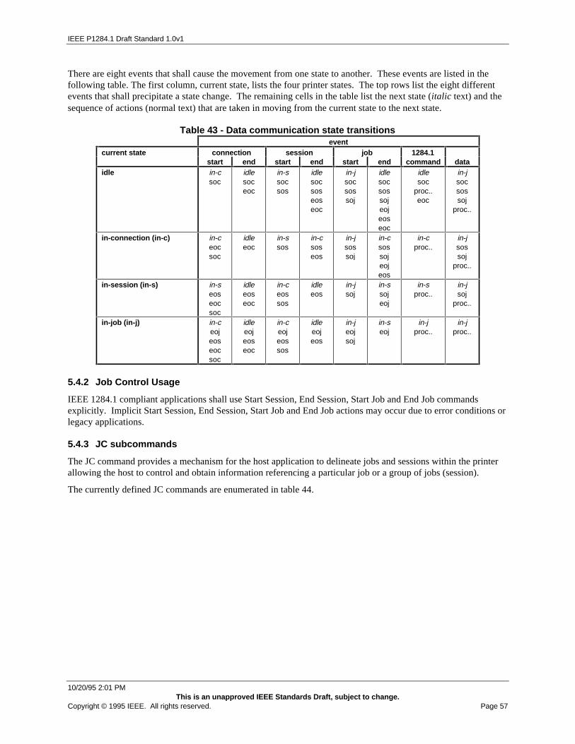
IEEE P1284.1 Draft Standard 1.0v1
10/20/95 2:01 PMThis is an unapproved IEEE Standards Draft, subject to change.
Copyright © 1995 IEEE. All rights reserved. Page 57
There are eight events that shall cause the movement from one state to another. These events are listed in thefollowing table. The first column, current state, lists the four printer states. The top rows list the eight differentevents that shall precipitate a state change. The remaining cells in the table list the next state (italic text) and thesequence of actions (normal text) that are taken in moving from the current state to the next state.
Table 43 - Data communication state transitionsevent
current state connection session job 1284.1start end start end start end command data
idle in-csoc
idlesoceoc
in-ssocsos
idlesocsoseoseoc
in-jsocsossoj
idlesocsossojeojeoseoc
idlesoc
proc..eoc
in-jsocsossoj
proc..
in-connection (in-c) in-ceocsoc
idleeoc
in-ssos
in-csoseos
in-jsossoj
in-csossojeojeos
in-cproc..
in-jsossoj
proc..
in-session (in-s) in-seoseocsoc
idleeoseoc
in-ceossos
idleeos
in-jsoj
in-ssojeoj
in-sproc..
in-jsoj
proc..
in-job (in-j) in-ceojeoseocsoc
idleeojeoseoc
in-ceojeossos
idleeojeos
in-jeojsoj
in-seoj
in-jproc..
in-jproc..
5.4.2 Job Control Usage
IEEE 1284.1 compliant applications shall use Start Session, End Session, Start Job and End Job commandsexplicitly. Implicit Start Session, End Session, Start Job and End Job actions may occur due to error conditions orlegacy applications.
5.4.3 JC subcommands
The JC command provides a mechanism for the host application to delineate jobs and sessions within the printerallowing the host to control and obtain information referencing a particular job or a group of jobs (session).
The currently defined JC commands are enumerated in table 44.

IEEE P1284.1 Draft Standard 1.0v1
10/20/95 2:01 PMThis is an unapproved IEEE Standards Draft, subject to change.
Page 58 Copyright © 1995 IEEE. All rights reserved.
Table 44. JC categoriesSubcommand Category Description
Start Job This command is sent to a logical unit within the printer prior to sending data to that logicalunit. It shall return to the host the Job ID that the host shall use for future reference to thatjob in the printer.
End Job This command is sent by the host to a logical unit within the printer after all of the data hasbeen sent. This marks the end of the physical entity referred to as a job.
Query Job(s) Completed This command can be used by the host to get the printer to return print statistics for jobscompleted by the printer. These statistics include the number of pages printed and thelength of time the job required.
Query Job(s) Queued or Active This command is sent by the host to obtain information about printer jobs not yetcompleted.
Start Session This command is sent to the printer to indicate the beginning of a session (a group ofrelated jobs) that are to follow. The printer shall return to the host a session ID that thehost shall use for future reference to the session in the printer.
End Session This command is sent by the host to the printer after all jobs have been sent for thesession
Query Session(s) Queued or Active This command is sent by the host to obtain information about printer sessions not yetcompleted.
Change Session Priority This command is sent by the host to change the priority of a session in the printer.Delete Session This command is sent by the host to delete a session in the printer.Resume Suspended Job This command is sent by the host to resume a suspended job.
The host controls jobs in the printer by sending a JC command with the desired subcommand. The subcommandis the first byte in the data field. Other bytes in the data field may be required parameters for the different JCsubcommands. Table 45 shows values for the currently defined JC subcommands.
Table 45. JC subcommandsValue-Hex Description
00 Start Job01 End Job02 Query Job(s) Completed03 Query Job(s) Queued or Active04-07 Reserved08 Start Session09 End Session0A Query Session(s) Queued or Active0B Change Session Priority0C Delete Session0D-0F Reserved10 Resume Suspended Job11-FF Reserved
5.4.4 Start Job
The JC Start Job subcommand (JC-SJ) is used by a host to indicate the start of a job for a given logical unit(interpreter). Using the JC-SJ subcommand the host registers to receive Job Control Alerts for the job. The printerresponse to the JC-SJ subcommand shall be a data packet that contains the job identification number that theprinter has assigned. The job identification number returned is used by the host to reference this job in future dataexchanges. These exchanges shall include marking the end of the job and requesting status or statistics. Table 46shows the format of the command sent from the host to the printer to signal the start of a job.

IEEE P1284.1 Draft Standard 1.0v1
10/20/95 2:01 PMThis is an unapproved IEEE Standards Draft, subject to change.
Copyright © 1995 IEEE. All rights reserved. Page 59
Table 46. JC-SJ commandBytes Value (hex) Description Notes
5 Job Control Packet Header1 00 Subcommand: Start Job Data Field1 ubyte Logical Unit Number (Interpreter)1 bbyte Job Alert Points
Bit 0 reservedBit 1 Logical Unit Start (zero=Off, one=On)Bit 2-5 reservedBit 6 Sheet Complete (zero=Off, one=On)Bit 7 Job Complete (zero=Off, one=On)
1 bbyte Processing FlagsBit 0 reservedBit 1 suspended at LU start (zero=No, one=Yes)Bit 2 reservedBit 3 suspend at start of printing (zero=No, one=Yes)Bit 4 reservedBit 5 suspend at start of finishing (zero=No, one=Yes)Bit 6 separate data channel (zero=No, one=Yes)Bit 7 retain incomplete sheet (zero=Off, one=On)
1 ubyte Length of Host String1-63 ASCII String Host String1 ubyte Length of User String1-63 ASCII String User String1 ubyte Length of Job Name String1-63 ASCII String Job Name String1 ubyte Length of Additional Information String1-63 ASCII String Additional Information String
If the host to printer message reply required flag (bit 4 of the flag byte) is set, and in the corresponding printer tohost reply message the error flag (bit 7 of the flag byte) is not set, the printer response to the JC-SJ subcommandshall be a message like the one depicted in table 47. If the host to printer message reply required flag is not set,no JC-SJ response will be issued.
Table 47. JC-SJ responseBYTES Value (hex) Description Notes
5 Job Control Packet Header1 00 Subcommand: Start Job Data Field1 ubyte Logical Unit Number (Interpreter)2 uword Printer Assigned Job ID
Note: The printer shall never assign a Job ID of 0000 as this valueis used in subsequent commands to request data on all jobsas opposed to a specific Job ID for any interpreter.
2 uword Printer Assigned Data Channel - a uword identifying the printerchannel number to used by the host to transfer the data; the channelnumber represents a transport-specific channel number (port). Ifthe channel number returned by the printer is zero, then it impliesthat the printer cannot perform data transfer via a separate channel,thereby requiring the host to use the control channel for datatransfer.
If the error flag is set, a data error (bits 2 and 3 of the flag byte) indicates that an undefined logical unit numberwas selected. No Job ID shall be returned.
If the host, for any reason, does not receive the message from the printer (error checking error, etc.), the same JobID can be returned by the printer if it is requested again prior to any data being sent to the same logical unitnumber. If the printer does not return the same Job ID, and no data has been sent to the same logical unit number,then the printer shall discard the internal Job ID for which no data has been sent without placing any statistics inthe job completed queue.
If a JC-SJ subcommand for a logical unit (interpreter) is sent by the host to the printer after the host has sent datato the same logical unit and prior to the host sending an JC End Job subcommand to that logical unit, the printer

IEEE P1284.1 Draft Standard 1.0v1
10/20/95 2:01 PMThis is an unapproved IEEE Standards Draft, subject to change.
Page 60 Copyright © 1995 IEEE. All rights reserved.
shall internally execute an implied JC End Job subcommand for this logical unit before processing the JC-SJsubcommand.
5.4.4.2 job alert points
5.4.4.2.1 logical unit start
When set, indicates that the printer shall send a JCA-LUS alert when the LU begins processing this job.
5.4.4.2.2 sheet complete
When set, indicates that the printer shall send a JCA-SC alert any time a sheet is deposited in the output bin as aresult of this job.
5.4.4.2.3 job complete
When set, indicates that the printer shall send a JCA-EOJ alert when the last sheet of this job is deposited in theoutput bin.
5.4.4.3 processing flags
5.4.4.3.1 suspend at logical unit start
When set, the LU shall suspend processing data from the input buffer associated with this LU when the dataassociated with this job reached the LU. The host shall then send a JCA-SP alert to inform the host. Whennotified, the host has the ability to send additional commands to the LU (outside the normal data stream) bysending data to LU+128. The printer shall allow this data to bypass the normal input buffers and route it directlyto the LU. Normal processing shall be continued when the host issues the JC-RSP command.
5.4.4.3.2 suspend at start of printing
When set, the LU shall suspend processing data for this job when the print data associated with this job reachesthe print engine. The host shall then send a JCA-SP alert to inform the host. Normal processing shall becontinued when the host issues the JC-RSP command.
5.4.4.3.3 suspend at start of finishing
When set, the LU shall suspend processing data for this job when the print media associated with this job reachesthe finisher. The host shall then send a JCA-SP alert to inform the host. Normal processing shall be continuedwhen the host issues the JC-RSP command.
5.4.4.3.4 retain incomplete sheet
If this flag is set and the LU supports it, the printer shall not image partial pages when the end of job command isreceived from the host. It is assumed that the host shall complete the image in a subsequent job within the currentsession.
5.4.5 End Job
The JC End Job subcommand (JC-EJ) is used by a host to indicate the end of a job started with the JC-SJsubcommand for a given logical unit (interpreter). The data sent from the host to the printer in the JC-EJsubcommand includes the logical unit number and the Job ID returned by the printer from a prior JC-SJsubcommand response. Table 48 shows the format of the command sent from the host to the printer.

IEEE P1284.1 Draft Standard 1.0v1
10/20/95 2:01 PMThis is an unapproved IEEE Standards Draft, subject to change.
Copyright © 1995 IEEE. All rights reserved. Page 61
Table 48. JC-EJ commandBYTES Value (hex) Description Notes
5 Job Control Packet Header1 01 Subcommand: End Job Data Field1 ubyte Logical Unit Number (Interpreter)2 uword Printer Assigned Job ID
It is recommended that the host set the reply required flag (bit 4 of the flag byte) in this message to the printer toreceive an acknowledgment from the printer that it has received and accepted the JC-EJ subcommand. With thereply required flag set, the printer shall respond to the JC-EJ subcommand with a message like the one depicted intable 49 if the error flag (bit 7 of the flag byte) is not set in the response the host receives from the printer.
Table 49. JC-EJ responseBYTES Value (hex) Description Notes
5 Job Control Packet Header1 01 Subcommand: End Job Data Field1 ubyte Logical Unit Number (Interpreter)2 uword Printer Assigned Job ID as specified in the JC-EJ subcommand that
prompted this reply.
The error flag shall be set, and a data error (indicated by bits 2 and 3 of the flag byte in the printer to hostmessage) shall be posted to indicate that an undefined logical unit number / Job ID pair was selected. Both thelogical unit number and a valid Job ID for that logical unit number shall be sent in the host to printer message fora data error not to be posted.
If the host, for any reason, does not receive the message from the printer (error checking error, etc.), the JC-EJsubcommand for the same logical unit number / Job ID can be sent again regardless of whether or not the printerhas internally marked the end of the job.
If the host sends a JC-EJ subcommand to a logical unit number following a JC-SJ subcommand without sendingany data to that logical unit between the JC-SJ and JC-EJ subcommands, the printer shall place an entry in the jobcompletion queue with zero valued job statistics, for those features (length and/or processing time) supported,with the unsupported features fields set to a binary value of all ones (max. value).
The printer shall ignore multiple JC-EJ subcommands and shall not return an error for a logical unit / Job ID pairif that combination is a valid job in the queue, in process, or completed and still remaining in the printer statisticsFIFO queue.
5.4.6 Query Job(s) Completed
The JC Query Job(s) Completed subcommand (JC-QJC) is used by the host to request statistics for jobs whichhave completed the printing process (e.g. stacked in the output tray). The time at which a job is consideredcompleted is defined to be when the last sheet has been stacked in the output feature to the best of the printer'sknowledge. The host can request this data at any time. It shall include data on the most recently completed jobs.The data, number of job statistics, shall be limited only by the size of the buffer in the printer that holds thisinformation.
Not knowing which job completed or on which logical unit a job has completed, it is required that the printermaintain a FIFO queue of at least 16 entries to hold job completion statistics. (The actual size of the queue isreturned in response to the RDC-RS subcommand.) This provides the host the capability of retrieving thestatistics for a particular job any time prior to the completion of the sixteenth job that follows. This shall give thehost ample time to obtain the information for a particular logical unit number / Job ID pair, even if the host has torequest it from the printer several times due to error checking protocols, etc..
Table 50 shows the format of the command sent from the host to the printer to request statistics for completedjobs.

IEEE P1284.1 Draft Standard 1.0v1
10/20/95 2:01 PMThis is an unapproved IEEE Standards Draft, subject to change.
Page 62 Copyright © 1995 IEEE. All rights reserved.
Table 50. JC-QJC commandBYTES Value (hex) Description Notes
5 Job Control Packet Header1 02 Subcommand: Query Job(s) Completed Data Field1 ubyte Logical Unit Number (Interpreter)
xx Return completed job statistics for this logical unit numberFF Return completed job statistics for all logical unit numbers
2 uword Requested Job ID0000 Return completed job statistics for all jobs for the above
specified logical unit number(s)xxxx Return completed job statistics for a specific job for the
above specified logical unit number.2 uword Maximum Number of Job Statistics to Return - Limit the printer to
host message to the this number of jobs that meet the above logicalunit number and Job ID criteria.
If the host to printer message reply required flag (bit 4 of the flag byte) is set, and in the corresponding printer tohost reply message the error flag (bit 7 of the flag byte) is not set, the printer response to the JC-QJC subcommandshall be a message like the one depicted in table 51. If the host to printer message reply required flag is not set,no JC-QJC response will be issued.
Table 51. JC-QJC responseBYTES Value (hex) Description Notes
5 Job Control Packet Header1 02 Subcommand: Query Job(s) Completed Data Field2 uword Number of job statistics records returned. Each record consists of:
logical unit number, Job ID, processing time, sheets used,impressions, and counter units for each input source supported bythis interpreter. Job data shall be returned in reverse order of jobcompletion within the printer. I.e. the last job completed shall be thefirst one reported.
1 ubyte (i) Number of input sources Job Statistic #11 ubyte Completed job #1 logical unit number2 uword Completed job #1 Job ID2 uword Completed job #1 processing time (in seconds)4 udword Completed job #1 sheets used from input source 14 udword Completed job #1 impressions from input source 14 udword Completed job #1 counter units from input source 1··· ··· ···4 udword Completed job #1 sheets used from input source i4 udword Completed job #1 impressions from input source i4 udword Completed job #1 counter units from input source i··· ··· ···
If the host requests statistics for more jobs than the printer has records to match, an error shall not occur . Theprinter shall return all job statistics that it has in the FIFO queue. The host shall know how many job statistics theprinter is sending via the value in the printer response that indicates the number of job statistics in the printer tohost message.
If the host requests statistics for fewer jobs than the printer has records to match, the printer shall return exactlythe number requested by the host. The statistics returned shall be in reverse chronological order (last jobcompleted reported first).
If the printer has not completed any jobs prior to the time it receives a host request for job statistics or does nothave any job statistics matching the selection criteria of the subcommand, the data field of the printer responseshall contain only one word, having a value of zero, indicating that no job statistics are available.
If the error flag is set, a data error indicates that the data field did not contain a value in the field that indicates thenumber of job statistics that shall be returned. No data shall be returned.

IEEE P1284.1 Draft Standard 1.0v1
10/20/95 2:01 PMThis is an unapproved IEEE Standards Draft, subject to change.
Copyright © 1995 IEEE. All rights reserved. Page 63
5.4.6.2 Counter Units
Counter units are defined in the RDC-RS subcommand response. A value returned with all bits set high indicatesthat the printer is incapable of reporting this information for this logical unit number.
If the counter units are defined as pages then this refers to the number of logical pages printed. In "two-up"printing there would be two logical pages per impression. In "four-up" printing there would be four logical pagesper impression.
For counter units other than pages, the fields for sheets and impressions are meaningless.
5.4.6.3 Sheets
A sheet is defined as a physical piece of print media, such as a sheet of paper. A value returned with all bits sethigh indicates that the printer is incapable of reporting this information for this logical unit number.
5.4.6.4 Impressions
An impression is defined as the number of sides printed on a sheet. Simplex print would have one impression persheet, whereas duplex print would have two impressions per sheet. A value returned with all bits set highindicates that the printer is incapable of reporting this information for this logical unit number.
5.4.6.5 Processing Time
If a printer provides support for processing time, the method for calculating time is dependent on theimplementation by the printer manufacturer. It is recommended that the processing time be the actual time thatthe printer spends processing the job. This would not include time spent waiting for an operator to service"intervention required" conditions, etc. A value returned with all bits set high indicates that the printer isincapable of reporting this information for this logical unit number.
5.4.7 Query Job(s) Queued or Active
The JC Query Job(s) Queued or Active subcommand (JC-QQA) is used by the host to obtain information on jobswhose processing has not started or not completed. The data returned by the printer shall indicate whether or notthe job is being held, whether or not it is waiting for processing to begin, or whether or not it is processing. Table52 shows the format of the command sent from the host to the printer requesting information regarding a job notyet completed processing by the printer.
Table 52. JC-QQA commandBYTES Value Description Notes
5 Job Control Packet Header1 03 Subcommand: Query Job(s) Queued or Active Data Field1 ubyte Logical Unit Number (Interpreter)
xx Return queued or active job data for this logical unit number
FF Return queued or active job data for all logical units2 uword Requested Job ID
0000 Return queued or active job data for all jobs for the abovespecified logical unit number(s).
xxxx Return queued or active job data for a specific job for theabove specified logical unit number.
The host can specify to return information for all queued or active jobs on all logical units, for all queued or activejobs on a specific logical unit number, or for a specific job on a specific logical unit number.
If the host to printer message reply required flag (bit 4 of the flag byte) is set, and in the corresponding printer tohost reply message the error flag (bit 7 of the flag byte) is not set, the printer response to the JC-QQAsubcommand shall be a message like the one depicted in table 53. If the host to printer message reply requiredflag is not set, no JC-QQA response will be issued.

IEEE P1284.1 Draft Standard 1.0v1
10/20/95 2:01 PMThis is an unapproved IEEE Standards Draft, subject to change.
Page 64 Copyright © 1995 IEEE. All rights reserved.
Table 53. JC-QQA responseBYTES Value Description Notes
5 Job Control Packet Header1 03 Subcommand: Query Job(s) Queued or Active Data Field1 ubyte
(n)Number of job detail records returned. Each record shall consists of10 bytes: logical unit number, Job ID, status, position & size. Jobdetail records can be returned in any order.
1 ubyte Queued or Active job #1 logical unit number2 uword Queued or Active job #1 Job ID1 ubyte Queued or Active job #1 status
00 Processing01 Waiting02 Held03 Suspended04 Waiting - Incomplete Sheet Retained04-7F Reserved80-FF Printer Specific
1 bbyte Queued or Active job #1 Job Processing PositionBit 0 ReservedBit 1 Logical Unit ProcessingBit 2 ReservedBit 3 Printing ProcessingBit 4 ReservedBit 5 Finishing ProcessingBit 6-7 Reserved
1 bbyte Queued or Active job #1 Job Suspension PositionBit 0 ReservedBit 1 Suspended at Logical Unit StartBit 2 ReservedBit 3 Suspended at Start of PrintingBit 4 ReservedBit 5 Suspended at Start of Finishing Bit 6-7 Reserved
4 Unsigned DoubleWord
Queued or Active job #1 size (in bytes)FFFFFFFF Not Supported
··· ··· ···1 ubyte Queued or Active job #n logical unit number2 uword Queued or Active job #n Job ID1 ubyte Queued or Active job #n status1 bbyte Queued or Active job #n Job Processing Position1 bbyte Queued or Active job #n Job Suspension Position
4Unsigned DoubleWord
Queued or Active job #n size (in bytes)FFFFFFFF Not Supported
The error flag shall be set, and a data error (indicated by bits 2 and 3 of the flag byte in the printer to hostmessage) shall be posted indicating that an undefined logical unit number / Job ID pair was selected. Both thelogical unit number and a valid Job ID for that logical unit number shall be sent in the host to printer message fora data error not to be posted.
5.4.8 Start Session
The JC Start Session subcommand (JC-SS) is used by a host to indicate the beginning of a collection of jobs. Theprinter shall use this command to lock port rotation in a multiple link and/or multiple protocol environment. Theprinter response to the JC-SS subcommand shall be a data packet that contains the session identification numberthat the printer has assigned. The session identification number returned is used by the host to reference thissession in future data exchanges. Table 54 shows the format of the command sent from the host to the printer tosignal the start of a job.

IEEE P1284.1 Draft Standard 1.0v1
10/20/95 2:01 PMThis is an unapproved IEEE Standards Draft, subject to change.
Copyright © 1995 IEEE. All rights reserved. Page 65
Table 54. JC-SS commandBytes Value (hex) Description Notes
5 Job Control Packet Header1 08 Subcommand: Start Session Data Field1 ubyte Requested Priority
00 = Invalid (cannot arbitrarily hold session when submitting)01 = Lowest PriorityFF = Highest Priority
If the host to printer message reply required flag (bit 4 of the flag byte) is set, and in the corresponding printer tohost reply message the error flag (bit 7 of the flag byte) is not set, the printer response to the JC-SS subcommandshall be a message like the one depicted in table 55. If the host to printer message reply required flag is not set,no JC-SS response will be issued.
Table 55. JC-SS responseBYTES Value (hex) Description Notes
5 Job Control Packet Header1 08 Subcommand: Start Session Data Field2 uword Printer Assigned Session ID
Note: The printer shall never assign a Session ID of 0000 as thisvalue is used in subsequent commands to request data onall sessions as opposed to a specific session.
1 ubyte Printer Assigned Priority (may not be the same as requested)
5.4.9 End Session
The JC End Session subcommand (JC-ES) is used by a host to indicate the end of a session started with the JC-SSsubcommand. The data sent from the host to the printer in the JC-ES subcommand includes the session IDreturned by the printer from the prior JC-SS subcommand response. Table 56 shows the format of the commandsent from the host to the printer.
Table 56. JC-ES commandBYTES Value (hex) Description Notes
5 Job Control Packet Header1 09 Subcommand: End Session Data Field2 uword Printer Assigned Session ID
It is recommended that the host set the reply required flag (bit 4 of the flag byte) in this message to the printer toreceive an acknowledgment from the printer that it has received and accepted the JC-ES subcommand. With thereply required flag set, the printer shall respond to the JC-ES subcommand with a message like the one depicted intable 57 provided that the error flag (bit 7 of the flag byte) is not set in the printer message.
Table 57. JC-ES responseBYTES Value (hex) Description Notes
5 Job Control Packet Header1 09 Subcommand: End Session Data Field2 uword Printer Assigned Session ID as specified in the JC-ES
subcommand that prompted this reply.1 ubyte Number of Jobs in this session1 ubyte Logical Unit number of 1st Job2 uword Printer Assigned Job ID of 1st Job
...
The error flag shall be set, and a data error (indicated by bits 2 and 3 of the flag byte in the printer to hostmessage) shall be posted indicating that an undefined session ID was selected. A valid session ID shall be sent inthe host to printer message for a data error not to be posted.

IEEE P1284.1 Draft Standard 1.0v1
10/20/95 2:01 PMThis is an unapproved IEEE Standards Draft, subject to change.
Page 66 Copyright © 1995 IEEE. All rights reserved.
If the host, for any reason, does not receive the message from the printer (error checking error, etc.), the JC-ESsubcommand for the same session ID can be sent again regardless of whether or not the printer has internallymarked the end of the session.
The printer shall ignore multiple JC-ES subcommands and shall not return an error for a session ID if the sessionID is a valid session in the queue, in process, or completed.
5.4.10 Query Session(s) Queued or Active
The JC Query Session(s) Queued or Active subcommand (JC-QSQA) is used by the host to obtain information onsessions whose processing has not started or not completed. The data returned by the printer shall indicatewhether or not the session is being held, whether or not it is waiting for processing to begin, or whether or not it isprocessing. Table 58 shows the format of the command sent from the host to the printer requesting informationregarding a job not yet completed processing by the printer.
Table 58. JC-QSQA commandBYTES Value Description Notes
5 Job Control Packet Header1 0A Subcommand: Query Session(s) Queued or Active Data Field2 uword Requested Session ID
0000 Return queued or active session data for all sessionsxxxx Return queued or active session data for a specific
session
The host can specify to return information for all queued or active sessions or for a specific session.
If the host to printer message reply required flag (bit 4 of the flag byte) is set, and in the corresponding printer tohost reply message the error flag (bit 7 of the flag byte) is not set, the printer response to the JC-QSQAsubcommand shall be a message like the one depicted in table 59. If the host to printer message reply requiredflag is not set, no JC-QSQA response will be issued.
Table 59. JC-QSQA responseBYTES Value Description Notes
5 Job Control Packet Header1 0A Subcommand: Query Session(s) Queued or Active Data Field1 ubyte (n) Number of session records returned1 ubyte Status of 1st session
00 Processing01 Waiting02 Held03 Suspended (a suspended job in a session causes a
suspended session)04-7F Reserved80-FF Printer Specific
1 ubyte Priority of 1st Session1 ubyte (i) Number of jobs in 1st session2 uword 1st Job ID in 1st Session
...2 uword Last Job ID in 1st Session
...
The error flag shall be set, and a data error (indicated by bits 2 and 3 of the flag byte in the printer to hostmessage) shall be posted indicating that an undefined session was selected.
5.4.11 Change Session Priority Subcommand
The JC Change Session Priority subcommand (JC-CSP) is used to change the priority of a session that is waitingin the printer's queue. The data sent from the host to the printer in the JC-CSP command consists of the sessionnumber returned by the printer from a prior JC-SS response. Table 60 shows the format of the command sentfrom the host to the printer.

IEEE P1284.1 Draft Standard 1.0v1
10/20/95 2:01 PMThis is an unapproved IEEE Standards Draft, subject to change.
Copyright © 1995 IEEE. All rights reserved. Page 67
If the requested session has already become active, this command shall not affect its priority.
Table 60. JC-CSP commandBYTES Value Description Notes
5 Job Control Packet Header1 0B Subcommand: Change Session Priority Data Field2 uword Printer assigned session ID for 1st session
0000 All sessions1 ubyte New priority for 1st session
00 hold session01 lowest priority...FF highest priority
It is recommended that the host set the reply required flag (bit 4 of the flag byte) in this message to the printer toreceive an acknowledgment from the printer that it has received and accepted the JC-CSP subcommand. With thereply required flag set, the printer shall respond to the JC-CSP command with a message like the one depicted intable 61 provided that the error flag (bit 7 of the flag byte) is not set in the printer message.
Table 61. JC-CSP responseBYTES Value Description Notes
5 Job Control Packet Header1 0B Subcommand: Change Session Priority Data Field1 ubyte Logical Unit Number (Interpreter)2 uword (n) Number of session priorities changed2 uword #1 Printer Assigned Session ID changed1 ubyte #1 session’s new priority...
If the error flag is set, a data error indicates no valid session ID was provided. For a session’s priority to bechanged, it shall either be waiting or held in the printer's queue. A request to change the priority of a session thatis not either waiting or held shall result in a data error.
If a request from the host is received to change the priority of all sessions and no sessions exist in the printer'squeue when the message is received, a data error shall not be posted. The resulting printer to host message's datafield shall contain a single zero valued byte indicating that no session priorities were changed.
5.4.12 Delete Session Subcommand
The JC Delete Session subcommand (JC-DS) is used by a host to remove a session from the printer. A sessionmay be deleted if it is in the printer's queue (waiting or held) or if it is processing. An immediate end of sessionshall be created within the printer for this session when this command is sent from the host to the printer.
If a member job is processing when its session is deleted, the printer shall place the job statistics at the time ofdeletion in the FIFO queue for this job.
If the session was waiting or held when it was canceled, the printer shall place statistics for the member jobs in theFIFO queue with zero values for length and processing time. If the printer was incapable of reporting lengthand/or processing time, for consistency the value placed in the unsupported field(s) shall be all ones instead ofzeros.
The data sent from the host to the printer for the JC-DS command consists of the session number returned by theprinter in a prior JC-SS response. Table 62 shows the format of the command sent from the host to the printer todelete a session.

IEEE P1284.1 Draft Standard 1.0v1
10/20/95 2:01 PMThis is an unapproved IEEE Standards Draft, subject to change.
Page 68 Copyright © 1995 IEEE. All rights reserved.
Table 62. JC-DS commandBYTES Value Description Notes
5 Job Control Packet Header1 0C Subcommand: Delete Session Data Field2 uword Printer Assigned Session ID to be canceled
0000 delete all sessionsxxxx session id to be deleted
It is recommended that the host set the reply required flag (bit 4 of the flag byte) in this message to the printer toreceive an acknowledgment from the printer that it has received and accepted the JC-DS subcommand. With thereply required flag set, the printer shall respond to the JC-DS subcommand with a message like the one depictedin table 63 provided that the error flag (bit 7 of the flag byte) is not set in the printer message.
Table 63. JC-DS responseBYTES Value Description Notes
5 Job Control Packet Header1 0C Subcommand: Delete Session Data Field2 uword Number of jobs canceled2 uword #1 Printer Assigned Session ID deleted··· ··· ···
If the error flag is set, a data error indicates that an undefined session ID was selected. For a session to be deleted,it shall be either in the printer's queue (held or waiting) or currently being processed by the printer. A request todelete a session that is not in one of these states shall cause the printer to return a data error.
If a request from the host is received to delete all sessions and no sessions are in the printer's queue when themessage is received, a data error shall not be posted. The resulting printer to host message's data field shallcontain a single, zero-valued byte indicating that there were no sessions deleted.
A data error shall be returned if the session has already been deleted.
5.4.13 Resume Suspended Job
The JC Resume Suspended Job (JC-RSJ) is used by the host to resume a job that has been suspended as a result ofthe host setting one or more of the processing flags in the JC-SJ command. Table 64 shows the format of thecommand sent from the host to the printer requesting information regarding a job not yet completed processing bythe printer.
Table 64. JC-RSJ commandBYTES Value Description Notes
5 Job Control Packet Header1 10 Subcommand: Resume Suspended Job Data Field1 ubyte Logical Unit Number (Interpreter)2 uword Suspended Job ID
5.5 Request Device Status (RDS)
5.5.1 Overview
The RDS command provides a mechanism for the host system to obtain status information regarding the operatingcondition of the printer. The host can obtain information concerning printer status in one of several categories.The printer shall always accept an RDS command without rejection due to lack of input buffer and processingspace. This means that the printer shall reserve buffer space to process at least one RDS command.
The status categories for which the host can retrieve information are shown in table 65.

IEEE P1284.1 Draft Standard 1.0v1
10/20/95 2:01 PMThis is an unapproved IEEE Standards Draft, subject to change.
Copyright © 1995 IEEE. All rights reserved. Page 69
Table 65. RDS CategoriesStatus Category Description
Input Those conditions in the printer where problems with the input of printing media can causethe printer to stop. These conditions can be normally be remedied by a normal operator.An example of this would be a particular input tray is empty.
Output Those conditions in the printer where problems with the output of printing media can causethe printer to stop. These conditions can be normally be remedied by a normal operator.An example of this would be a particular output tray is full.
Jam Those conditions in the printer where normal conditions associated with the movement ofprinting media through the printer can cause it to stop, these conditions can be correctedby a normal operator. An example of this would be "jam at input tray".
Supplies Those conditions in the where normal conditions in the printer associated with suppliescan cause it to stop, these conditions can be corrected by a normal operator. An exampleof this would be " out of Ink".
Operator Intervention Required Those conditions in the printer, other than input, output, jam or printing supplies, that cancause the printer to stop, these conditions can be corrected by a normal operator. Anexamples of this would be "Cover Open".
Warnings Those conditions that are not critical to the immediate operation of the printer: Examplesare:- Paper Input Low- Toner Low- Output Bin Nearly Full
Device Service Required Those conditions that are critical to printer operation that a normal operator can not correctand requires technical service. Examples are:- Laser Polygon Scanner inoperative- High Fuser Temperature
Configuration Change Those conditions that are detected that change the current configuration of the printer.Examples are:- Memory Board Failure resulting in reduced memory.- Font Cartridge/Card has been removed
Printer Statistics Those printer specific statistics that are kept by the printing mechanism. An example is thetotal number of pages printed by the printer.
The host selects the category of printer status information desired by sending a RDS command with asubcommand in the data field that specifies the category of information desired.
The subcommand values for the various categories of status information to be returned by the printer are shown intable 66.
Table 66. RDS SubcommandsValue - Hex Category Description Notes
00 Summary01 Input Status02 Output Status03 Input Alert04 Output Alert05 Jam Alert06 Operator Intervention Required Alert07 Warnings08 Device Service Alert09 Configuration Change Alert0A Supplies Alert0B Printer Statistics0C Supplies Status0C - FF Reserved
5.5.2 Request Status Summary
The RDS Request Status Summary subcommand (RDS-RSS) provides the host system with an overview of thecurrent status of the printer. The data returned by the printer allows the host to determine the printer's operational

IEEE P1284.1 Draft Standard 1.0v1
10/20/95 2:01 PMThis is an unapproved IEEE Standards Draft, subject to change.
Page 70 Copyright © 1995 IEEE. All rights reserved.
status and if any printer conditions exist that would require operator intervention or attention. Table 67 shows theformat of the command sent to the printer to request the status summary.
Table 67. RDS-RSS CommandBytes Value - Hex Description Notes
5 Request Device Status Packet Header1 00 Subcommand: Request Status Summary Data Field
After the printer receives the command it shall return a status summary packet back to the host as shown in table68.
Table 68. RDS-RSS ResponseBytes Value-hex Description Notes
5 Request Device Status Packet Header1 00 Subcommand: Request Status Summary Data Field1 Bit Encoded Overall Printer Status Summary1 Bit Encoded Device Alerts 1 - Printer Status Alerts #11 Bit Encoded Device Alerts 2 - Printer Status Alerts #2
5.5.2.2 Overall Printer Status Summary
5.5.2.2.1 Overall Printer Status Summary Codes
This is a bit encoded field that provides an overview of the current operating condition of the printer. The bitdefinitions are shown in table 69
Table 69. RDS-RSS Overall Printer Status Summary codesBit Description Notes
0 Power On Initialization zero=No one=Yes1 Reserved2 Reserved3 Reserved4 Reserved5 Printer Idle zero=No one=Yes6 Printer Off-line zero=No one=Yes7 Data Link Buffer Full zero=No one=Yes
5.5.2.2.2 Bit 7 - Data Link Buffer Full
The printer shall set the data link buffer full bit when any condition prevents the printer from continuing to acceptdata packets. The full indicator shall not be set if there are warning conditions that do not interfere with theimmediate operation of the printer such as toner low in a electrophotograhic printer.
The printer shall always accept an RDS command regardless of the state of the full indicator. When full, theprinter may reject commands other than the RDS command but this is printer implementation dependent.
When this bit is set the host shall check the other status and alert condition indicators within this data packet todetermine if the condition was caused by anything other than a link buffer full condition.
5.5.2.2.3 Bit 6 - Off-line,
An off-line condition exists if an operator action or condition in the printer would cause the printer to halt theprinting process pending action by an operator. If an off-line condition exists then this bit shall be set. When off-line, the printer may reject commands other than the RDS command but this is printer implementation dependent.
5.5.2.2.4 Bits 5 - Printer Idle,
The printer is inactive, awaiting instructions from a host.

IEEE P1284.1 Draft Standard 1.0v1
10/20/95 2:01 PMThis is an unapproved IEEE Standards Draft, subject to change.
Copyright © 1995 IEEE. All rights reserved. Page 71
5.5.2.2.5 Bits 1 thru 4 - Reserved
These bits are reserved for future standardization. To ensure system upward compatibility these bits shall be set toa zero value.
5.5.2.2.6 Bit 0 - Power On Initialization,
Power On Initialization shall occur any time the printer performs a power on initialization or any other sequencewhere internal variables or states are returned to values equal to those resulting from a power on initialization.This bit and the Power On Initialization alert bit in the DSA shall be cleared after the Status Summary response issent to the host.
5.5.2.3 Device Alerts 1 and 2 - Printer Status Alerts #1 and #2
These bit encoded fields are used to indicate the status of device alerts in the printer. Each bit corresponds to adifferent device alert category. If that bit has a value of zero there is no active alert for that category. If the bit isa one, then an alert is active. If an active alert is indicated, the host can inquire about the details of that alert usingthe appropriate RDS subcommand. Tables 70 and 71 define the bits and their associated alert categories.
Table 70. RDS-RSS Device Alerts 1 codesBit Alert Category Notes
0 Printing Supply Alert1 Paper Jam Alert2 Output Alert3 Input Alert4 Reserved5 Reserved6 Reserved7 Reserved
Table 71. RDS-RSS Device Alerts 2 codesBit Alert Category Notes
0 Configuration Change Alert1 Warnings Alert2 Device Service Required Alert3 Operator Intervention Required Alert4 Reserved5 Reserved6 Reserved7 Reserved
5.5.3 Request Input Status
The RDS Request Input Status subcommand (RDS-RIS) provides the host system with an overview of the status ofprinting media inputs. The host system can request status for inputs individually or collectively. Table 72 showsthe format of the command sent to the printer.
Table 72. RDS-RIS CommandBytes Value - Hex Description Notes
5 Request Device Status Packet Header1 01 Subcommand: Request Input Status Data Field1 ubyte Input ID
00 = Return Status of All Inputsxx = Return Data Concerning a specific input
The identification numbers for the various input devices of the printer are assigned by the printer. The host systemobtains the identification numbers initially by issuing a RDC-RIC command requesting that the printer return dataconcerning all inputs.

IEEE P1284.1 Draft Standard 1.0v1
10/20/95 2:01 PMThis is an unapproved IEEE Standards Draft, subject to change.
Page 72 Copyright © 1995 IEEE. All rights reserved.
Table 73 shows the format of the data packet returned to the host when the printer receives a RDS-RIS command.
Table 73. RDS-RIS ResponseBytes Value - Hex Description Notes
5 Request Device Status Packet Header1 01 Subcommand: Request Input Status Data Field1 ubyte Number of Inputs IDs reporting1 ubyte Input ID Number 1 Input 12 bword Current Status of Input - Standard··· ··· ···
5.5.3.2 Number of Input IDs Reporting
This unsigned byte defines how many inputs for which the printer shall be returning data. If the host requestedstatus about a specific input, then this number shall be a value of one. If the status of all inputs was requested thenthe number shall be the total number of inputs currently installed on the printer.
5.5.3.3 Input Identification Number
This unsigned byte is the logical number that the printer has assigned to a particular input that the following datashall describe.
5.5.3.4 Current Status of Input - Standard
5.5.3.4.1 Input Status codes
This is a bit encoded word that describes the current status of a particular input. This field is reserved for standarddefinitions of printer status. The bits are defined in table 74.
An alert shall be posted if paper (print media) is attempted to be fed from an empty or missing input paper source.
Table 74. RDS-RIS Input Status codesBit Description Notes
0 Current Input Level Bit 0 Paper picked with1 Current Input Level Bit 1 these 3 bits = 02 Current Input Level Bit 2 shall cause a
DSA3 On Request / Tray Missing zero=No one=Yes Paper picked with
this bit = one shallcause a DSA
4 Unavailable / Broken zero=No one=Yes5 Busy / Temporarily Unavailable zero=No one=Yes6-14 Reserved15 Alert Active zero=No one=Yes
5.5.3.4.2 Bit 15 - Alert Active
This bit provides an indication if an alert is active for this input device. If this bit has a value of zero then there isno alert active for this input.
5.5.3.4.3 Bit 6-14 - Reserved
These bits are reserved for future standardization. To ensure system upward compatibility these bits shall be set toa value of zero.
5.5.3.4.4 Bit 5 - Busy / Temporarily Unavailable
This bit set indicates that the tray is allocated to some other process and is unavailable at this time. It shall returnto an available state at a future time with no operator intervention.

IEEE P1284.1 Draft Standard 1.0v1
10/20/95 2:01 PMThis is an unapproved IEEE Standards Draft, subject to change.
Copyright © 1995 IEEE. All rights reserved. Page 73
5.5.3.4.5 Bit 4 - Unavailable / Broken
This bit set indicates that the tray is broken or unavailable. Intervention by an operator is required to correct thiscondition.
5.5.3.4.6 Bit 3 - On Request / Tray Missing
This bit indicates that a paper tray or other like device associated with the input is missing. A value of zero for thebit indicates that the tray is present.
5.5.3.4.7 Bits 0, 1, 2 - Current Input Level
These three bits together form a binary value that indicates the current level of printing media for the input deviceto the printer. Bit 0 is considered the least significant bit and bit 2 is considered the most significant bit. A binaryvalue of zero for these bits indicate the input is empty and a value of seven indicates a full input. Values betweenzero and seven indicate various degrees of input capacity with the exact meaning printer implementationdependent.
5.5.4 Request Output Status
The RDS Request Output Status subcommand (RDS-ROS) provides the host system with an overview of the statusof printing media output. The host system can request status of outputs individually or collectively. Table 75 showthe format of the command sent to the printer.
Table 75. RDS-ROS CommandBytes Value - Hex Description Notes
5 Request Device Status Packet Header1 02 Subcommand: Request Output Status Data Field1 ubyte Output ID
00 = Return Status of All Outputsxx = Return Data Concerning a specific output
The identification numbers for the various output devices of the printer are assigned by the printer. The hostsystem initially obtains the identification numbers using the RDC-ROC command asking the printer to returninformation for all outputs.
After the printer receives the RDS-ROS command it shall return a data packet back to the host similar to the oneshown in table 76.
Table 76. RDS-ROS ResponseBytes Value - Hex Description Notes
5 Request Device Status Packet Header1 02 Subcommand: Request Output Status Data Field1 ubyte Number of Outputs IDs reporting1 ubyte Output ID Number 1 Output 12 bword Current Status of Output··· ··· ···
5.5.4.2 Number of Output IDs Reporting
This unsigned byte defines the number of outputs for which data shall be returned. If the host requested statusabout a specific output, then this number shall be a value of one. If the status of all outputs was requested then thenumber shall be the total number of outputs currently installed on the printer.
5.5.4.3 Output Identification Number
This unsigned byte is the logical number that the printer has assigned to a particular output.

IEEE P1284.1 Draft Standard 1.0v1
10/20/95 2:01 PMThis is an unapproved IEEE Standards Draft, subject to change.
Page 74 Copyright © 1995 IEEE. All rights reserved.
5.5.4.4 Current Status of Output
5.5.4.4.1 Output Status codes
This is a bit encoded word that describes the current status of a particular output. This field is reserved forstandard definitions of printer status. The bits are defined in table 77.
An alert shall be posted if the last sheet of paper (print media) is stacked in the output tray causes the output toreach capacity or if an attempt is made to stack a sheet in a tray that is missing.
Table 77. RDS-ROS Output Status codesBit Description Notes
0 Current Output Level Bit 0 Output attempt1 Current Output Level Bit 1 with 3 bits = one2 Current Output Level Bit 2 shall cause a
DSA3 On Request / Tray Missing zero=No one=Yes Output attempt
with bit = oneshall cause aDSA
4 Unavailable / Broken zero=No one=Yes5 Busy / Temporarily Unavailable zero=No one=Yes6-14 Reserved15 Alert Active zero=No one=Yes
5.5.4.4.2 Bit 15 - Alert Active
This bit provides an indication if an alert is active for this output device. If this bit has a value of zero then there isno alert active for this bit.
5.5.4.4.3 Bit 6-14 - Reserved
These bits are reserved for future standardization. To ensure system upward compatibility these bits shall be set toa value of zero.
5.5.4.4.4 Bit 5 - Busy / Temporarily Unavailable
This bit set indicates that the tray is allocated to some other process and is unavailable at this time. It shall returnto an available state at a future time with no operator intervention.
5.5.4.4.5 Bit 4 - Unavailable / Broken
This bit set indicates that the tray is broken or unavailable. Intervention by an operator is required to correct thiscondition.
5.5.4.4.6 Bit 3 - On Request / Tray Missing
This bit indicates that a paper tray or other like device associated with the output is missing. A value of zero forthe bit indicates that the tray is present.
5.5.4.4.7 Bits 0, 1, 2 - Current Output Level
These there bits together form a binary value that indicates the current level on printing media for the outputdevice to the printer. Bit 0 is considered the least significant bit and bit 2 is considered the most significant bit. Abinary value of zero for these bits indicate the output is empty and a value of seven indicates a full output. Valuesbetween zero and seven indicate various degrees of output capacity with the exact meaning for a particular valuebeing printer implementation dependent.

IEEE P1284.1 Draft Standard 1.0v1
10/20/95 2:01 PMThis is an unapproved IEEE Standards Draft, subject to change.
Copyright © 1995 IEEE. All rights reserved. Page 75
5.5.5 Request Input Alert
The RDS Request Input Alert subcommand (RDS-RIA) provides the host system the status of all inputs that haveactive alerts. The format of the command sent to the printer is shown in table 78.
Table 78. RDS-RIA CommandBytes Value - Hex Description Notes
5 Request Device Status Packet Header1 03 Subcommand: Request Input Alert Data Field
After the printer receives the RDS-RIA command it shall return a data packet to the host similar to the one shownin table 79.
Table 79. RDS-RIA ResponseBytes Value - Hex Description Notes
5 Request Device Status Packet Header1 03 Subcommand: Request Input Alert Data Field1 ubyte Number of Input IDs reporting an Alert
00 = No Input alert active (following Data omitted)1 ubyte Input ID Number Input 12 bword Current Status of Input 11 ubyte (n) Length of Alert Message 1n ASCII Alert Message 1··· ··· ···
5.5.5.2 Current Status of Input
The data returned for this field is the same as that returned when the host issues a RDS-RIS command.
5.5.6 Request Output Alert
The RDS Request Output Alert subcommand (RDS-ROA) provides the host system the status of all outputs thathave active alerts. The format of the command sent to the printer is shown in table 80.
Table 80. RDS-ROA CommandBytes Value - Hex Description Notes
5 Request Device Status Packet Header1 04 Subcommand: Request Output Alerts Data Field
After the printer receives the RDS-ROA command it shall return a data packet to the host similar to the one shownin table 81.
Table 81. RDS-ROA ResponseBytes Value - Hex Description Notes
5 Request Device Status Packet Header1 04 Subcommand: Request Output Alert Data Field1 ubyte Number of Output IDs reporting an Alert
00 = No Output alert active (following Data omitted)1 ubyte Output ID Number Output 12 bword Current Status of Output 11 ubyte (n) Length of Alert Message 1n ASCII Alert Message 1··· ··· ···
5.5.6.2 Number of Output IDs Reporting an Alert
This unsigned byte is the total number of printer outputs that have active alerts. If there are no outputs with activealerts this field shall be zero. When this field has a value of zero no additional data shall be returned in the datapacket.

IEEE P1284.1 Draft Standard 1.0v1
10/20/95 2:01 PMThis is an unapproved IEEE Standards Draft, subject to change.
Page 76 Copyright © 1995 IEEE. All rights reserved.
5.5.6.3 Current Status of Output
The data returned for this field is the same as that returned when the host issues a RDS-ROS command.
5.5.7 Request Jam Alert
The RDS Request Jam Alert subcommand (RDS-RJA) provides the host with information about printing mediajam conditions. The format of the command sent to the printer is shown in table 82.
Table 82. RDS-RJA CommandBytes Value - Hex Description Notes
5 Request Device Status Packet Header1 05 Subcommand: Request Jam Alert Data Field
The printer responds to the RDS-RJA command by sending data to the host concerning all jam conditions that canbe currently identified, their location and input/output identification number(s). Table 83 shows the format of thedata returned.
Table 83. RDS-RJA ResponseBytes Value - Hex Description Notes
5 Request Device Status Packet Header1 05 Subcommand: Request Jam Alert Data Field1 ubyte Number of Jam Alerts reporting
00 = No Jam Alert Active - the following data shall not be included1 ubyte Location of Jam Alert Number 1 Jam #11 ubyte ID of Location of Jam Alert 1
i.e. - Input ID, Output IDFF = Unknown
1 ubyte Position1 ubyte (n) Length of Alert Message #1 in bytes (not including this byte)n ASCII Alert Message #1··· ··· ···
5.5.7.2 Number of Jam Alerts Reporting
This unsigned byte indicates the total number of jam locations that the printer has detected. For each jam locationthree bytes and an associated ASCII string shall be returned. The three bytes specify the location, locationidentification number, and position. If there are no jam conditions existing in the printer at the time the commandis received the value of this field shall be set to zero and no additional data returned in the data packet.
5.5.7.3 Location of Jam Alert
This unsigned byte specifies the general location of a jam alert within the printer. Table 84 defines the valuesassociated with the different printer locations. If the location of the jam can not be specified a value of 255 shallbe returned.

IEEE P1284.1 Draft Standard 1.0v1
10/20/95 2:01 PMThis is an unapproved IEEE Standards Draft, subject to change.
Copyright © 1995 IEEE. All rights reserved. Page 77
Table 84. RDS-RJA Location codesValue - Hex Description Notes
00 Reserved01 Input02 Output03 Internal04 Duplex05 External06 Stacker07 Finisher08 Marker09 Logical Unit0A to FD ReservedFE OtherFF Unknown
5.5.7.4 ID
This byte returns the identification number of the location of the jam that was specified by the previous byte. Forexample if the jam occurred at an input, this byte would contain the identification number of the particular inputwhere the jam occurred. If the printer could not determine the identification number the printer shall return avalue of 255 in this byte.
5.5.7.5 Position
If an input device supports multiple positions, this byte would be used to report the position within the inputdevice were the jam occurred. If the printer could not determine the position, the printer shall return a value of255 in this byte.
5.5.7.6 Length of Alert Message in Bytes
This is an unsigned byte that defines the length of the following alert message. The value does not include thisbyte in the count. A value of zero indicates that there is no message to follow.
5.5.7.7 Alert Message
This ASCII field is a message associated with a particular alert. The first part of the message is recommended tobe an ASCII alphanumeric string delimited by a space character (hex 20) specifying a manufacturer's alert codefor the remainder of the ASCII string. If there is no manufacturer's alert code associated with the ASCII string,the string is recommended to begin with a space character. The remainder of the ASCII string (that following thefirst space character) is recommended to be a human readable message of the appropriate language detailing thealert condition.
5.5.8 Request Operator Intervention Required Alert
The RDS Request Operator Intervention Required Alerts subcommand (RDS-ROIRA) provides the host withinformation about those conditions in the printer that can cause the printer to stop printing. Operator InterventionRequired conditions (OIR) are situations that can be corrected by a normal or non-technical operator. An exampleof this type of message would be: "Cover Open". OIR alerts do not include those conditions that are covered in theinput, output, and jam alert categories.
For each OIR alert the printer shall return a location, an ID, and an error code with an associated ASCII text stringthat describes the particular alert. The host can use the text string to display the message to the user and use thelocation, ID, and error code as an index entry into a table if additional processing is required. The printer mayhave more than one OIR alert active at any given time. All OIR alerts active in the printer shall be returned whenthe host requests OIR alerts from the printer. The host requests the OIR alerts by sending a RDS-ROIRAcommand as shown in table 85.

IEEE P1284.1 Draft Standard 1.0v1
10/20/95 2:01 PMThis is an unapproved IEEE Standards Draft, subject to change.
Page 78 Copyright © 1995 IEEE. All rights reserved.
Table 85. RDS-ROIRA CommandBytes Value - Hex Description Notes
5 Request Device Status Packet Header1 06 Subcommand: Request Operator Intervention Required Alerts Data Field
The response by the printer to the RDS-ROIRA command is shown in table 86.
Table 86. RDS-ROIRA ResponseBytes Value - Hex Description Notes
5 Request Device Status Packet Header1 06 Subcommand: Request Operator Intervention Required Alerts Data Field1 ubyte Number of alert messages to follow1 ubyte Location #1 Alert #11 ubyte ID #11 ubyte Alert Code #11 ubyte (n) Length of Alert Message #1 in bytes (not including this byte)n ASCII Alert Message #1··· ··· ···
5.5.8.2 Number of Alert Messages to follow
This unsigned byte is the total number of OIR alerts active in the printer and the number of message fields tofollow in the data packet.
5.5.8.3 Location of Alert
This unsigned byte specifies the general location of the alert within the printer. Table 84 defines the valuesassociated with the different locations with in the printer. If the location of the alert can not be specified a value of255 shall be returned.
5.5.8.4 ID
This byte returns the identification number of the location of the alert that was specified by the previous byte. Avalue of 255 in this byte indicates that an ID does not exist for this alert.
5.5.8.5 Alert Code
This is an unsigned byte that specifies the type of OIR alert. This byte is used by the host system to search throughtables for additional error handling procedures that may be required or for printer specific error codes. Table 87shows the alert codes and their description.
Table 87. RDS-ROIRA codes and messagesAlert Code Alert Description Notes
00 Reserved01 "Cover or Door Open or Ajar"02 "Waste Toner Box Full"03 "Print Ribbon Jam"04 "Waste Ink Reservoir Full"05 to FD ReservedFE OtherFF Unknown
5.5.8.6 Length of Alert Message in Bytes
This is an unsigned byte that defines the length of the following alert message. The value does not include thisbyte in the count. A value of zero indicates that there is no message to follow.

IEEE P1284.1 Draft Standard 1.0v1
10/20/95 2:01 PMThis is an unapproved IEEE Standards Draft, subject to change.
Copyright © 1995 IEEE. All rights reserved. Page 79
5.5.8.7 Alert Message
This ASCII field is a message associated with a particular alert. The first part of the message is recommended tobe an ASCII alphanumeric string delimited by a "blank" specifying a manufacturer's alert code for the remainderof the ASCII string. If there is no manufacturer's alert code associated with the ASCII string, the string isrecommended to begin with a "blank". The remainder of the ASCII string (that following the first "blank") isrecommended to be a human readable message of the appropriate language detailing the alert condition.
5.5.9 Request Warnings
The RDS Request Warnings subcommand (RDS-RW) provides the host with information about warningconditions which currently exist in the printer. Warnings are conditions in the printer that are not critical toimmediate operation. Examples of warnings are "Paper Input Low", "Toner Low" or "Output Bin nearly Full".
For each warning the printer shall return a location, an ID, and a warning code with an associated ASCII textstring that describes the particular warning. The host can use the text string to display the message to the user anduse the location, ID, and warning code as an index entry into a table if additional processing is required. Theprinter may have more than one warning active at any one time. All warnings active in the printer shall bereturned when the host requests the warnings from the printer. Table 88 shows the format of the command sent tothe printer.
Table 88. RDS-RW CommandBytes Value - Hex Description Notes
5 Request Device Status Packet Header1 07 Subcommand: Request Warnings Data Field
The response by the printer to the RDS-RW command is shown in table 89.
Table 89. RDS-RW ResponseBytes Value - Hex Description Notes
5 Request Device Status Packet Header1 07 Subcommand: Request Warnings Data Field1 ubyte Number of warning messages to follow1 ubyte Location #1 Warning #11 ubyte ID #11 ubyte Warning Code #11 ubyte (n) Length of Warning Message #1 in bytes (not including this byte)n ASCII Warning Message #1··· ··· ···
5.5.9.2 Number of Warning Messages to follow
This unsigned byte is the total number of warning messages active in the printer and the number message fields tofollow in the data packet.
5.5.9.3 Location of Warning
This unsigned byte specifies the general location of the warning within the printer. Table 84 defines the valuesassociated with the different locations with in the printer. If the location of the warning can not be specified avalue of 255 shall be returned.
5.5.9.4 ID
This byte returns the identification number of the location of the warning that was specified by the previous bytethat indicated the location. For example, if multiple toner supply units can generate the "Toner Supply Low"warning then this byte can be used to distinguish which toner supply unit is low. A value of 255 in this byteindicates that an ID does not exist for this alert.

IEEE P1284.1 Draft Standard 1.0v1
10/20/95 2:01 PMThis is an unapproved IEEE Standards Draft, subject to change.
Page 80 Copyright © 1995 IEEE. All rights reserved.
5.5.9.5 Warning Code
This is an unsigned byte that specifies the type of warning. Table 90 shows the warning codes and theirdescription.
Table 90. RDS-RW codes and descriptionsAlert Code Alert Description Notes
00 Reserved01 "Toner Supply Low"02 "Ink Supply Low"03 "Paper Input Low"04 "Output Bin Nearly Full"05 "Cover or Panel Open"06 "Fusing Supplies Low"07 "Other"08 “Supply Low”09 “Supply Nearly Full”0A “Supply Missing”0B to FD ReservedFE OtherFF Unknown
5.5.9.6 Length of Warning Message in Bytes
This is an unsigned byte that defines the length of the following warning message. The value does not include thisbyte in the count. A value of zero indicates that no warning message is to follow.
5.5.9.7 Warning Message
This ASCII field is a message associated with a particular warning type. The first part of the message isrecommended to be an ASCII alphanumeric string delimited by a "blank" specifying a manufacturer's warningcode for the remainder of the ASCII string. If there is no manufacturer's warning code associated with the ASCIIstring, the string is recommended to begin with a "blank". The remainder of the ASCII string (that following thefirst "blank") is recommended to be a human readable message of the appropriate language detailing the alertcondition.
5.5.10 Device Service Required Alerts
The RDS Request Device Service Required Alerts subcommand (RDS-RDSRA) provides the host withinformation about those conditions in the printer that can cause the printer to stop printing. Device ServiceRequired (DSR) conditions are situations that cannot be corrected by a normal or non-technical operator. Anexample of this type of message would be: "Laser Polygon Scanner Inoperative". DSR Alerts do not include thoseconditions that are covered in the input, output, and jam alert categories.
For each DSR alert the printer shall return a location, an ID, and an error code with an associated ASCII textstring that describes the particular alert. The host can use the text string to display the message to the user and usethe location, ID, and error code as an index entry into a table if additional processing is required. The printer mayhave more than one DSR alert active at any time. All DSR alerts active in the printer shall be returned when thehost requests the DSR alerts from the printer. Table 91 shows the format of the command sent to the printer.
Table 91. RDS-RDSRA CommandBytes Value - Hex Description Notes
5 Request Device Status Packet Header1 08 Subcommand: Request Device Service Required Alerts Data Field
The response by the printer to the RDS-RDSRA command is shown in table 92.

IEEE P1284.1 Draft Standard 1.0v1
10/20/95 2:01 PMThis is an unapproved IEEE Standards Draft, subject to change.
Copyright © 1995 IEEE. All rights reserved. Page 81
Table 92. RDS-RDSRA ResponseBytes Value - Hex Description Notes
5 Request Device Status Packet Header1 08 Subcommand: Request Device Service Required Alerts Data Field1 ubyte Number of alert messages to follow1 ubyte Location #1 Alert #11 ubyte ID #11 ubyte Alert Code #11 ubyte (n) Length of Alert Message #1 in bytes (not including this byte)n ASCII Alert Message #1··· ··· ···
5.5.10.2 Number of Alert Messages to follow
This unsigned byte is the total number of DSR alert messages active in the printer and the number of messagefields to follow in the data packet.
5.5.10.3 Location of Alert
This unsigned byte specifies the general location of the alert within the printer. Table 84 defines the valuesassociated with the different locations with in the printer. If the location of the alert can not be specified a value of255 shall be returned.
5.5.10.4 ID
This byte returns the identification number of the location of the alert that was specified by the previous byte. Avalue of 255 in this byte indicates that an ID does not exist for this alert.
5.5.10.5 Alert Code
This is an unsigned byte that specifies the code associated with the DSR alert. Table 93 shows the error codes.
Table 93. RDS-RDSRA codes and messagesAlert Code Alert Description Notes
00 Reserved01 "Hard Error"
A hard error is one that cannot be recovered from.02 "Soft Error"
A soft error is an error that was detected and may or may not persist.03 to FE ReservedFF Unknown
5.5.10.6 Length of Alert Message in Bytes
This is an unsigned byte that defines the length of the following alert message. The value does not include thisbyte in the count. A value of zero indicates that no message follows.
5.5.10.7 Alert Message
This ASCII field is a message associated with a particular alert. The first part of the message is recommended tobe an ASCII alphanumeric string delimited by a "blank" specifying a manufacturer's alert code for the remainderof the ASCII string. If there is no manufacturer's alert code associated with the ASCII string, the string isrecommended to begin with a "blank". The remainder of the ASCII string (that following the first "blank") isrecommended to be a human readable message of the appropriate language detailing the alert condition.
5.5.11 Request Configuration Change Alert
The RDS Request Configuration Change Alert subcommand (RDS-RCCA) provides the host with informationabout conditions that were detected that changed the current configuration of the printer. A configuration change

IEEE P1284.1 Draft Standard 1.0v1
10/20/95 2:01 PMThis is an unapproved IEEE Standards Draft, subject to change.
Page 82 Copyright © 1995 IEEE. All rights reserved.
alert may or may not be critical to the immediate operation of the printer. Examples of alerts are "Font CartridgeRemoved" or "RAM memory board failure". If the host receives a Configuration Change Alert, the host shallmake the appropriate inquiries of the printer to access the extent of the change and to verify the current printerstate.
For each alert the printer shall return a location, an ID, and an error code with an associated ASCII text string thatdescribes the particular alert. The host can use the text string to display the message to the user and use thelocation, ID, and error code as an index entry into a table if additional processing is required. The printer mayhave more than one alert active at any time. All active alerts in the printer shall be returned when the host send theRDS-RCCA command to the printer. Table 94 shows the format of the command sent to the printer.
Table 94. RDS-RCCA CommandBytes Value - Hex Description Notes
5 Request Device Status Packet Header1 09 Subcommand: Request Configuration Change Alerts Data Field
The printer response to the RDS-RCCA command is shown in Table 95.
Table 95. RDS-RCCA ResponseBytes Value - Hex Description Notes
5 Request Device Status Packet Header1 09 Subcommand: Request Configuration Change Alerts Data Field1 ubyte Number of Alert messages to follow1 ubyte Location #1 Alert #11 ubyte ID #11 ubyte Alert Code #11 ubyte (n) Length of Alert Message #1 in bytes (not including this byte)n ASCII Alert Message #1··· ··· ···
5.5.11.2 Number of Alert Messages to follow
This unsigned byte is the total number of alert messages active in the printer and the number message fields tofollow in the data packet.
5.5.11.3 Location of Alert
This unsigned byte specifies the general location of the alert within the printer. Table 84 defines the valuesassociated with the different locations with in the printer. If the location of the alert can not be specified a value of255 shall be returned.
5.5.11.4 ID
This byte returns the identification number of the location of the alert that was specified by the previous byte. Avalue of 255 in this byte indicates that an ID does not exist for this alert.
5.5.11.5 Alert Code
This is an unsigned byte that specifies the code associated with the alert message. Table 96 shows the alert codesand their descriptions.

IEEE P1284.1 Draft Standard 1.0v1
10/20/95 2:01 PMThis is an unapproved IEEE Standards Draft, subject to change.
Copyright © 1995 IEEE. All rights reserved. Page 83
Table 96. RDS-RCCA codes and descriptionsAlert Code Alert Description Notes
00 Reserved01 "Interpreter Related Resource Deleted"02 "Interpreter Related Resource Added"03 "Reserved"04 "Medium Size Changed"05 "Cartridge Removed" Not related to a06 "Cartridge Installed" data stream07 "Installed Memory Reduced"08 "Installed Memory Increased"09 “Option Removed”0A “Option Installed”0B - FD ReservedFE "Configuration Change" ----- Printer unable to classify change, but there is a
way that the host can query the printer and determine the specific change byinterpreting the printer's responses.
FF Unknown
5.5.11.6 Length of Alert Message in Bytes
This is an unsigned byte that defines the length of the following alert message. The value does not include thisbyte in the count. A value of zero indicates that no message is to follow.
5.5.11.7 Alert Message
This ASCII field is a message associated with a particular alert. The first part of the message is recommended tobe an ASCII alphanumeric string delimited by a "blank" specifying a manufacturer's alert code for the remainderof the ASCII string. If there is no manufacturer's alert code associated with the ASCII string, the string isrecommended to begin with a "blank". The remainder of the ASCII string (that following the first "blank") isrecommended to be a human readable message of the appropriate language detailing the alert condition.
5.5.12 Supplies Alerts
The RDS Request Supplies Alerts subcommand (RDS-RSA) provides the host with information about thoseconditions associated with supplies in the printer that cause the printer to stop printing. Supplies alert conditionsare situations that can be corrected by a normal or non-technical operator. An example of this type of messagewould be: "Out of Ink" or "Out of Toner".
For each alert the printer shall return a location, an ID, and an error code with an associated ASCII text string thatdescribes the particular alert. The host can use the text string to display the message to the user and use thelocation, ID, and error code as an index entry into a table if additional processing is required. The printer mayhave more than one supplies alert active at any time. All active supplies alerts in the printer shall be returnedwhen the host send the RDS-RSA command to the printer. Table 97 shows the format of the command sent to theprinter.
Table 97. RDS-RSA CommandBytes Value - Hex Description Notes
5 Request Device Status Packet Header1 0A Subcommand: Request Supplies Alerts Data Field
The printer response to the RDS-RSA command is shown in table 98.

IEEE P1284.1 Draft Standard 1.0v1
10/20/95 2:01 PMThis is an unapproved IEEE Standards Draft, subject to change.
Page 84 Copyright © 1995 IEEE. All rights reserved.
Table 98. RDS-RSA ResponseBytes Value - Hex Description Notes
5 Request Device Status Packet Header1 0A Subcommand: Request Supplies Alerts Data Field1 ubyte Number of alert messages to follow1 ubyte Location #1 Alert #11 ubyte ID #11 ubyte Alert Code #11 ubyte (n) Length of Alert Message #1 in bytes (not including this byte)n ASCII Alert Message #1··· ··· ···
5.5.12.2 Number of Alert Messages to Follow
This unsigned byte is the total number of active supplies alert messages in the printer and the number of messagefields to follow in the data packet.
5.5.12.3 Location of Alert
This unsigned byte specifies the general location of the alert within the printer. Table 84 defines the valuesassociated with the different locations with in the printer. If the location of the alert can not be specified a value of255 shall be returned.
5.5.12.4 ID
This byte returns the identification number of the location of the alert that was specified by the previous byte. Avalue of 255 in this byte indicates that an ID does not exist for this alert.
5.5.12.5 Alert Code
This is an unsigned byte that specifies the code associated with the supplies alert message. Table 99 shows thealert codes and descriptions.
Table 99. RDS-RSA codes and descriptionsAlert Code Alert Description Notes
00 Reserved01 "Out of Toner"02 "Out of Ink"03 "Ribbon Out"04 “Supply Missing”05 “Supply Empty”06 “Supply Full”07 to FD ReservedFE OtherFF Unknown
5.5.12.6 Length of Alert Message in Bytes
This is an unsigned byte that defines the length of the following alert message. The value does not include thisbyte in the count. A value of zero indicates that no alert message is to follow.
5.5.12.7 Alert Message
This ASCII field is a message associated with a particular alert. The first part of the message is recommended tobe an ASCII alphanumeric string delimited by a "blank" specifying a manufacturer's alert code for the remainderof the ASCII string. If there is no manufacturer's alert code associated with the ASCII string, the string isrecommended to begin with a "blank". The remainder of the ASCII string (that following the first "blank") isrecommended to be a human readable message of the appropriate language detailing the alert condition.

IEEE P1284.1 Draft Standard 1.0v1
10/20/95 2:01 PMThis is an unapproved IEEE Standards Draft, subject to change.
Copyright © 1995 IEEE. All rights reserved. Page 85
5.5.13 Request Printer Statistics
The RDS Request Printer Statistics subcommand (RDS-RPS) provides the host system with statistics that are keptby the printer. These statistics are related to the overall printer and not necessarily related to any one particularprinting job or period of time. Table 100 shows the format of the RDS-RPS command sent by the host to theprinter.
Table 100. RDS-RPS CommandBytes Value - Hex Description Notes
5 Request Device Status Packet Header1 0B Subcommand: Request Printer Statistics Data Field
Upon receiving the RDS-RPS command the printer shall issue a response similar to the one shown in table 101.
Table 101. RDS-RPS ResponseBytes Value - Hex Description Notes
5 Request Device Status Packet Header1 0B Subcommand: Request Printer Statistics Data Field1 ubyte Number of Statistics Reporting1 ubyte Statistic Type Statistic 14 Unsigned Double
WordStatistic Value
··· ··· ···
5.5.13.2 Number of Statistics Reporting
This unsigned byte defines the number of statistics that this printer response contains. If the value is zero then theprinter does not have the capability to report any statistics and there shall not be any additional data to follow.
5.5.13.3 Statistic Type
This unsigned byte defines type of statistic the printer is reporting. Table 102 defines the codes and its associatedprinter statistic.
Table 102. RDS-RPS codesValue Description Notes
00 Reserved01 Total counter units printed since beginning of printer Life02 Total counter units printed since printer power on03 Total counter units on current printing supplies04 Total counter units on host controlled counter05 - FE ReservedFF Unknown
5.5.13.3.2 Total Counter Units Since Beginning of Printer Life
This statistic is the total number of counter units (e.g. pages, inches, etc.) printed since the initial manufacture ofthe printer. This counter is defined by the manufacturer and cannot be reset by the host.
5.5.13.3.3 Total Counter Units Since Power On
This statistic is the total number of counter units (e.g. pages, inches, etc.) printed since the last time the printer hasbeen turned on. This counter is only reset when the printer executes its power on initialization sequence.
5.5.13.3.4 Total Counter Units On Current Printing Supplies
This counter is the total number of counter units (e.g. pages, inches, etc.) printed on the current printing supplies.For example this is the number of pages printed since the toner cartridge or ribbon was changed in a laser printeror impact printer. The method of resetting the counter is dependent on the manufacture of the printer.

IEEE P1284.1 Draft Standard 1.0v1
10/20/95 2:01 PMThis is an unapproved IEEE Standards Draft, subject to change.
Page 86 Copyright © 1995 IEEE. All rights reserved.
5.5.13.3.5 Host Controlled Counter
This statistic is the total number of counter units (e.g. pages, inches, etc.) printed since the last time the counterhas been reset. This counter is reset in one of two ways. First, the counter is reset every time the printer executesits power on initialization sequence. Second, the host can reset the counter by sending a "Reset Host ControlledCounter" subcommand of the Printer Configuration Control command.
5.5.13.4 Statistic Value
This unsigned double word is the value associated with the previous statistic type field. The units associated withthis value are defined by the printer and reported in the counter units field of the RDC-RS command.
5.5.14 Request Supplies Status
The RDS Request Supplies Status subcommand (RDS-RSS) provides the host with an overview of the status ofsupplies other than input medium of the printer. Table 67 shows the format of the RDS-RSS command sent to theprinter.
Table 103. RDS-RSS CommandBytes Value - Hex Description Notes
5 Request Device Status Packet Header1 0C Subcommand: Request Supplies Status Data Field1 ubyte Supply ID
00 = Return Status of All Supplies
The printer's response to the RDS-RSS command is shown in table 68.
Table 104. RDS-RSS ResponseBytes Value - Hex Description Notes
5 Request Device Status Packet Header1 0C Subcommand: Request Supplies Status Data Field1 ubyte Number of Supply IDs reporting1 ubyte Location #1 Supply ID #11 ubyte ID #12 bword Current Status of Supplies #1··· ··· ···
5.5.14.2 Number of Supply IDs reporting
This unsigned byte defines how many supplies for which the printer shall be returning data.
5.5.14.3 Location of Supply
This unsigned byte specifies the general location of the supply within the printer. Table 84 defines the valuesassociated with the different locations with in the printer. If the location of the supply can not be specified a valueof 255 shall be returned.
5.5.14.4 ID
This byte returns the identification number of the location of the supply that was specified by the previous byte.A value of 255 in this byte indicates that an ID does not exist for this supply.
5.5.14.5 Current Status of Supplies
This is a bit encoded byte that describes the current status of the expendable printing supplies (ribbon, ink, toner,etc.). This field is reserved for standard definitions of printer status. The bit definitions for this byte are shown intable 105.
An alert shall be posted if an attempted is made to use an empty supply.

IEEE P1284.1 Draft Standard 1.0v1
10/20/95 2:01 PMThis is an unapproved IEEE Standards Draft, subject to change.
Copyright © 1995 IEEE. All rights reserved. Page 87
Table 105. RDS-RSS codesBit Description Notes
0 Supplies Level Bit 01 Supplies Level Bit 12 Supplies Level Bit 23-14 Reserved15 Alert Active zero=Noone=Yes
5.5.14.5.2 Bit 15 - Alert Active
This bit provides an indication if an alert is active for this printing supply. If this bit has a value of zero then thereis no alert active.
5.5.14.5.3 Bits 3-14 - Reserved
These bits are reserved for future standardization. To ensure system upward compatibility these bits shall be set toa value of zero.
5.5.14.5.4 Bits 2, 1, 0 - Supplies Level
These three bits together form a binary value that indicates the current level of the standard printing supplies (e.g.black ink, toner, ribbon, etc.). Bit 0 is the least significant bit and bit 2 is the most significant bit. A binary valueof zero for these bits indicate the supply is empty and a value of seven indicates that it is full. Values betweenzero and seven indicate various degrees of supply on hand with the exact meaning printer implementationdependent.
5.6 Printer Configuration Control (PCC)
5.6.1 Overview
The PCC command can be used by the host to set various parameters to configure operations within a printer thatsupports the 1284.1 protocol. The PCC subcommands are shown in table 106.
Table 106. PCC subcommandsValue Description Notes
00 Read Current Printer Configuration01 Reset Printer02 deprecated03 Select Device Status Alerts04 Data Loop Back05 Select Host Packet Size06 Reset Host Controlled Counter07 Select Interpreter Messages08 Read Interpreter Messages Selected09 Select Job Alerts0A Read Job Alerts Selected0B Set Printer ID0C Enable Common Printer MIB Alert0D Disable Common Printer MIB Alert0E Read Printer ID0F to FF Reserved
5.6.2 Read Current Printer Configuration
The PCC Read Current Printer Configuration command (PCC-RCPC) allows the host to read the active printersettings selected through prior use of the PCC command. Table 107 shows the format of the PCC-RCPCcommand.

IEEE P1284.1 Draft Standard 1.0v1
10/20/95 2:01 PMThis is an unapproved IEEE Standards Draft, subject to change.
Page 88 Copyright © 1995 IEEE. All rights reserved.
Table 107. PCC-RCPC CommandBytes Value - Hex Description Notes
5 Printer Configuration Control Packet Header1 00 Subcommand: Read Current Printer Configuration Data Field
The printer shall respond to the PCC-RCPC command with a response similar to the one shown in table 108.
Table 108. PCC-RCPC ResponseBytes Value - Hex Description Notes
5 Printer Configuration Control Packet Header1 00 Subcommand: Read Current Printer Configuration Data Field2 uword Maximum Size in Bytes of the Data Packet to be Sent to the Host1 bbyte Overall Printer Status Standard Enabled
Bit 0 - Power On Initialization, always a oneBits 1-5 - Reserved, always a zeroBit 6 - Printer Off-line AlertsBit 7 - Printer Busy Alerts
Value of zero=DoNOT Send DSAMessage for thecategory ofPrinter Status
1 Bit Encoded Device Alerts Byte 1 EnabledBit 0 - Printing Supply AlertsBit 1 - Paper Jam AlertsBit 2 - Output AlertsBit 3 - Input AlertsBits 4-7 - Reserved, always a zero
Value ofone=Send DSAMessage for thecategory ofPrinter Status
1 Bit Encoded Device Alerts Byte 2 EnabledBit 0 - Configuration Change AlertsBit 1 - Warning AlertsBit 2 - Device Service Required AlertsBit 3 - Operator Intervention AlertsBits 4-7 - Reserved, always a zero
1 Bit Encoded Deprecated
5.6.3 Reset Printer
The PCC Reset Printer command (PCC-RP) allows the host to reset the printer. Using the PCC-RP command theprinter can be placed in various reset states by host. Table 109 shows the format of the PCC-RP command sent tothe printer.
Table 109. PCC-RP CommandBytes Value - Hex Description Notes
5 Printer Configuration Control Packet Header1 01 Subcommand: Reset Printer Data Field1 ubyte Type of Reset
01 Reset printer to power on condition. This returns the printer to the1284.1 initialized state, downloaded resources shall be deleted (orwhatever normally happens to them when a Power-On-Reset occurs).
02. Reset 1284.1 Layer only and leave rest of printer, interpreter, in currentconfiguration. This reset does not affect resources or the operatingenvironment associated with the interpreters that are active.
03. Reset printer to power on condition and exit 1284.1. This reset does notpreserve any temporary resources as in #1.
04. Reset Printer and exit 1284.1. 1284.1 does not exist until the printer isreset. Temporary resources are preserved.
05-FF ReservedReset 1284.1 State Comm Link State Interpreter01 1284.1 Default Default02 1284.1 Default Unchanged03 non-1284.1 non-1284.1 default Default04 non-1284.1 non-1284.1 default Unchanged

IEEE P1284.1 Draft Standard 1.0v1
10/20/95 2:01 PMThis is an unapproved IEEE Standards Draft, subject to change.
Copyright © 1995 IEEE. All rights reserved. Page 89
5.6.4 Select Device Status Alerts
The PCC Select Device Status Alerts command (PCC-SDSA) allows the host to arm the conditions within theprinter for which the printer shall transmit a Device Status Alert (DSA) message to the host. Table 110 shows theformat of the PCC-SDSA command.
Table 110. PCC-SDSA CommandBytes Value - Hex Description Notes
5 Printer Configuration Control Packet Header1 03 Subcommand: Select Device Status Alerts Data Field1 bbyte Overall Printer Status Standard
Bit 0 - Power On Initialization, ignoredBits 1-4 - Reserved, shall be zeroBit 5 - Printer Idle Alerts zero=No, one=YesBit 6 - Printer Off-line Alerts zero=No, one=YesBit 7 - Data Link Buffer Full Alerts zero=No, one=Yes
1 bbyte Device Alerts Byte 1Bit 0 - Printing Supply Alerts zero=No, one=YesBit 1 - Paper Jam Alerts zero=No, one=YesBit 2 - Output Alerts zero=No, one=YesBit 3 - Input Alerts zero=No, one=YesBits 4-7 - Reserved, shall be zero
1 bbyte Device Alerts Byte 2Bit 0 - Configuration Change Alert zero=No, one=YesBit 1 - Warnings zero=No, one=YesBit 2 - Device Service Required Alerts zero=No, one=YesBit 3 - Operator Intervention Alerts zero=No, one=YesBits 4-7 - Reserved, shall be zero
If a condition that would cause a DSA is active at the time that its DSA is armed using the PCC-SDSA command,then a DSA shall be sent.
The reset condition is that all conditions that cause DSA messages are disabled until explicitly enabled by thehost.
5.6.5 Data Loop-Back
The PCC Data Loop-Back command (PCC-DLB) provides a means for the host to test the communication link tothe printer. Using the PCC-DLB command the host sends data to the printer that upon reception by the printershall immediately be sent back to the host. The minimum packet size that is supported is 64 bytes. The maximumpacket size can not exceed the Maximum Receive Command Packet Size as specified in the RDC-RS response.The Continue bit in the Flag byte of the Packet Header shall be ignored on this command. Table 111 shows theformat of the PCC-DLB command.
Table 111. PCC-DLB CommandBytes Value - Hex Description Notes
5 Printer Configuration Control Packet Header1 04 Subcommand: Data Loop Back Data Fieldn Data to be Sent To the Printer
Table 112 shows the format of the printer's response to the PCC-DLB command.
Table 112. PCC-DLB ResponseBytes Value - Hex Description Notes
5 Printer Configuration Control Packet Header1 04 Subcommand: Data Loop Back Data Fieldn Data to be Sent Back to the Host

IEEE P1284.1 Draft Standard 1.0v1
10/20/95 2:01 PMThis is an unapproved IEEE Standards Draft, subject to change.
Page 90 Copyright © 1995 IEEE. All rights reserved.
5.6.6 Select Host Packet Size
The PCC Select Host Packet Size command (PCC-SHPS) is sent by the host to the printer to set the maximum sizedata packet that the printer can use when sending data to the host. The packet size specifies the length of the entiredata packet including the start of packet byte, length bytes, command, subcommand, and data bytes. If the amountof data the printer has to send to the host exceeds the maximum size set by the host, then it shall send the data inmultiple packets. Table 113 shows the format of the PCC-SHPS command.
The printer shall always initialize the maximum host packet size to 64 bytes, the default packet size, during poweron initialization.
The PCC-RP command shall not change this value.
Table 113. PCC-SHPS CommandBytes Value - Hex Description Notes
5 Printer Configuration Control Packet Header1 05 Subcommand: Select Host Packet Size Data Field2 uword Maximum Size in Bytes of the Data Packet to be Sent to the Host
5.6.7 Reset Host Controlled Counter
The PCC Reset Host Controlled Counter command (PCC-RHCC) is used by the host to reset the host controlledcounter which tallies counter units. This counter shall only be reset by the PCC-RHCC command or by power oninitialization.
The value of the host controlled counter is read using the RDS-RPS command.
Table 114. PCC-RHCC CommandBytes Value - Hex Description Notes
5 Printer Configuration Control Packet Header1 06 Subcommand: Reset Host Controlled Counter Data Field
5.6.8 Select Unsolicited Interpreter Messages
The PCC Select Unsolicited Interpreter Messages command (PCC-SUIM) allows the host to disable/enable theprinter to return to the host unsolicited messages from an interpreter. These are responses that the interpretergenerates on its own independent of the 1284.1 command layer. Table 115 shows the format of the PCC-SUIMcommand.
Table 115. PCC-SUIM CommandBytes Value - Hex Description Notes
5 Printer Configuration Control Packet Header1 07 Subcommand: Select Interpreter Messages Data Field1 ubyte Logical Unit Number (Interpreter)
00 Default Interpreterxx Enable or Disable Interpreter Messages for this interpreter
1 bbyte Enable Interpreter Status Alerts #1Bit 0 - Response to Interpreter Queries (zero=No, one=Yes, zero=default)Bits 1-7 - Reserved
1 bbyte Enable Interpreter Status Alerts #2Bits 0-7 - Reserved
5.6.9 Read Interpreter Messages Selected
The PCC Read Interpreter Messages Selected command (PCC-RIMS) allows the host to view the printer settingsas to whether or not unsolicited interpreter messages of a particular category shall be returned to the host ordiscarded within the printer. These are responses that the interpreter generates on its own independent of the1284.1 command layer. Table 120 shows the format of the PCC-RIMS command.

IEEE P1284.1 Draft Standard 1.0v1
10/20/95 2:01 PMThis is an unapproved IEEE Standards Draft, subject to change.
Copyright © 1995 IEEE. All rights reserved. Page 91
Table 116. PCC-RIMS CommandBytes Value - Hex Description Notes
5 Printer Configuration Control Packet Header1 08 Subcommand: Read Interpreter Messages Selected Data Field1 ubyte Logical Unit Number (Interpreter)
00 Default Interpreterxx Specific Interpreter
Table 117 shows the format of the printer's response to the PCC-RIMS command.
Table 117. PCC-RIMS ResponseBytes Value - Hex Description Notes
5 Printer Configuration Control Packet Header1 08 Subcommand: Read Interpreter Messages Selected Data Field1 ubyte Logical Unit Number (Interpreter)
00 Default Interpreterxx Specific Interpreter
1 bbyte Enable Interpreter Status Alerts #1Bit 0 - Response to Interpreter Queries (zero=No, one=Yes)Bits 1-7 - Reserved
1 bbyte Enable Interpreter Status Alerts #2Bits 0-7 - Reserved
5.6.10 Select Job Alerts
The PCC Select Job Alerts command (PCC-SJA) allows the host to disable/enable the printer to return to the hostjob alerts. Table 118 shows the format of the PCC-SJA command.
Table 118. PCC-SJA CommandBytes Value - Hex Description Notes
5 Printer Configuration Control Packet Header1 09 Subcommand: Select Job Alerts Data Field1 bbyte Job Alert Points
Bit 0 reservedBit 1 Logical Unit Start (zero=Off, one=On)Bit 2 reservedBit 3 reservedBit 4 Page Alert (zero=Off, one=On)Bit 5 reservedBit 6 End of Job (zero=Off, one=On)Bit 7 Job Accounting (zero=Off, one=On)
5.6.11 Read Job Alerts Selected
The PCC Read Job Alerts Selected command (PCC-RJAS) allows the host to view the printer settings as towhether or not job alerts shall be returned to the host. Table 119 shows the format of the PCC-RJAS command.
Table 119. PCC-RJAS CommandBytes Value - Hex Description Notes
5 Printer Configuration Control Packet Header1 0A Subcommand: Read Job Alerts Selected Data Field
Table 120 shows the format of the printer's response to the PCC-RJAS command.

IEEE P1284.1 Draft Standard 1.0v1
10/20/95 2:01 PMThis is an unapproved IEEE Standards Draft, subject to change.
Page 92 Copyright © 1995 IEEE. All rights reserved.
Table 120. PCC-RJAS ResponseBytes Value - Hex Description Notes
5 Printer Configuration Control Packet Header1 0A Subcommand: Read Job Alerts Selected Data Field1 bbyte Job Alert Points
Bit 0 reservedBit 1 Logical Unit Start (zero=Off, one=On)Bit 2 reservedBit 3 reservedBit 4 reservedBit 5 reservedBit 6 Extended Job Complete (zero=Off, one=On)Bit 7 Job Accounting (zero=Off, one=On)
5.6.12 Set Printer ID
The PCC Set Printer ID command (PCC-SPI) is used by the host to set the ASCII string that is to be returned inthe JCA-EOJ accounting message alert from the printer. The Printer ID's power on initialization state is its serialnumber.
Table 121. PCC-SPI CommandBytes Value - Hex Description Notes
5 Printer Configuration Control Packet Header1 0B Subcommand: Set Printer ID Data Field1 ubyte Length of Printer ID1-63 ASCII Printer ID
5.6.13 Read Printer ID
The PCC Read Printer ID command (PCC-RPI) is used by the host to read the ASCII string that the printer shallreturn in the JCA-EOJ accounting message. Table 122 describes the format of the command sent from the host tothe printer. Table 123 describes the response to the command from the printer.
Table 122. PCC-RPI CommandBytes Value - Hex Description Notes
5 Printer Configuration Control Packet Header1 0E Subcommand: Read Printer ID Data Field
Table 123. PCC-RPI ResponseBytes Value - Hex Description Notes
5 Printer Configuration Control Packet Header1 0E Subcommand: Read Printer ID Data Field1 ubyte Length of Printer ID1-63 ASCII Printer ID
5.6.14 Enable Common Printer MIB Alert
The PCC Enable Common Printer MIB Alert command (PCC-EMA) is used by the host to enable the sending ofthe asynchronous message indicating that a critical alert entry has been added to the alert table as defined byRFC1759.
Table 124. PCC-EMA CommandBytes Value - Hex Description Notes
5 Printer Configuration Control Packet Header1 0C Enable Common Printer MIB Alert Data Field

IEEE P1284.1 Draft Standard 1.0v1
10/20/95 2:01 PMThis is an unapproved IEEE Standards Draft, subject to change.
Copyright © 1995 IEEE. All rights reserved. Page 93
5.6.15 Disable Common Printer MIB Alert
The PCC Disable Common Printer MIB Alert command (PCC-DMA) is used by the host to disable the sending ofthe asynchronous message indicating that a critical alert entry has been added to the alert table.
Table 125. PCC-DMA CommandBytes Value - Hex Description Notes
5 Printer Configuration Control Packet Header1 0D Disable Common Printer MIB Alert Data Field
5.7 Request Logical Unit Characteristics (RLUC)
5.7.1 Overview
The RLUC command provides a means for a host application to obtain information about the different logicalunits in the printer. A given logical unit within the printer may provide support for a page description languageinterpreter (only type currently defined), scanner, etc. The fact that it is possible to have different characteristicsfor logical units necessitates this command for future growth.
The RLUC command is contained in the packet header and the subcommand, which selects the specific logicalunit characteristic information to be retrieved from the printer, is contained in the data field. The specific RLUCsubcommands available to the host are identified in table 126.
Table 126. RLUC categoriesSubcommand Category Description
Summary Information This command is sent to the printer by the host to request a summary of the functionalsupport provided by a specific logical unit.
The values for the subcommands for host requests of logical unit characteristic information are shown in table127.
Table 127. RLUC subcommandsValue-Hex Description Notes
00 Summary Information Required01-FF Reserved
5.7.2 Summary Information
The RLUC Summary Information command (RLUC-SI) is used by a host to request the capabilities of a givenlogical unit within the printer. Table 128 shows the format of the RLUC-SI command.
Table 128. RLUC-SI CommandBYTES Value Description Notes
5 Request Logical Unit Characteristics Packet Header1 00 Subcommand: Summary Information Data Field1 ubyte Logical Unit Number (Interpreter)
00 Return data for the current interpreter assigned to LU #0xx Specific LU # requestedFF Return data for all LU #'s
This host message is meaningful only if the reply required flag (bit 4 of the flag byte) is set. With the replyrequired flag set, the printer shall respond to the RLUC-SI command with a message like the one depicted in table129 provided that the error flag (bit 7 of the flag byte) is not set in the response the host receives from the printer.

IEEE P1284.1 Draft Standard 1.0v1
10/20/95 2:01 PMThis is an unapproved IEEE Standards Draft, subject to change.
Page 94 Copyright © 1995 IEEE. All rights reserved.
Table 129. RLUC-SI ResponseBYTES Value Description Notes
5 Request Logical Unit Characteristics Packet Header1 00 Subcommand: Summary Information Data Field1 ubyte Number of Logical Unit Numbers (Interpreter) for which data is
returned in this message1 ubyte #1 Logical Unit Number Logical Unit #12 uword #1 Logical Unit Identifier
0000 Page Description or Page Control Interpreter0001 Scanner0002 Modem0003 FAX0001-7FFF Reserved8000-FFFF Manufacturer Specific
··· ··· ···
If the error flag is set, a data error (bits 2 and 3 of the flag byte) indicates that an undefined logical unit numberwas selected. No summary information shall be returned.
5.7.2.2 Number of Logical Unit Numbers
This byte indicates the number of logical unit numbers for which summary information is returned within thismessage. If summary information was requested for a specific interpreter this number shall be 1.
5.7.2.3 Logical Unit Number
This byte indicates the number that the printer shall use to reference this logical unit.
5.7.2.4 Logical Unit Identifier
This unsigned word defines the Logical Unit type. This field is a value encoded field which defines the varioustype of Logical Units.
5.8 Printer Variable Commands (PVC)
5.8.1 Overview
The PVC commands are provided to allow the host to manipulate internal printer variables over any linkregardless of the underlying transport protocol. These commands allow access to objects that would be accessibleby SNMP if an agent was present.
The following table lists the various subcommands available to the host for manipulating these variables.Implementation of this command is not required for compliance to this standard.
Table 130. PVC SubcommandsSubcommand Description
Get Printer Variable Get a variable from the printerSet Printer Variable Set a variable in the printerGet Next Printer Variable Get the next variable from the printer
5.8.2 Get Printer Variable
The PVC Get Printer Variable subcommand (PVC-GPV) shall be used by a host to get a variable from the printer.

IEEE P1284.1 Draft Standard 1.0v1
10/20/95 2:01 PMThis is an unapproved IEEE Standards Draft, subject to change.
Copyright © 1995 IEEE. All rights reserved. Page 95
Table 131. PVC-GPV CommandBytes Value (hex) Description Notes
5 PVC Command Packet Header1 00 Get Printer Variable Data Field2 uword Length of the variable namen ASCII Variable name
If the printer successfully executes the requested command a response shall be returned to the host similar to theone shown in the following table.
5.8.2.2 Variable Name
The variable name is an ASCII string encoding an object ID as defined in any RFC that the printer may choose toimplement. For example: RFC1213 defines the MIB-II variable sysDescr. The variable name for this object, asdefined in RFC1213, is 1.3.6.1.2.1.1.1.0
Table 132. PVC-GPV Successful ResponseBytes Value - Hex Description Notes
5 PVC Command Packet Header1 00 Get Printer Variable Data Field1 00 Request Successfully Completed2 uword Length of the variable namen ASCII Variable name2 uword Length of the variable value1 ubyte Variable type
00 = Integer01 = String
n Variable value
If the printer fails to execute the requested command a response shall be returned to the host similar to the oneshown in the following table.
Table 133. PVC-GPV Failed ResponseBytes Value - Hex Description Notes
5 PVC Command Packet Header1 00 Get Printer Variable Data Field1 ubyte Request Failed
01 = Too big02 = No such name05 = General Error
5.8.3 Set Printer Variable
The PVC Set Printer Variable subcommand (PVC-SPV) shall be used by a host to set a variable in the printer.
Table 134. PVC-SPV CommandBytes Value (hex) Description Notes
5 PVC Command Packet Header1 01 Set Printer Variable Data Field2 uword Length of the variable namen ASCII Variable name2 uword Length of the variable valuen Variable value
If the printer successfully executes the requested command a response shall be returned to the host similar to theone shown in the following table.

IEEE P1284.1 Draft Standard 1.0v1
10/20/95 2:01 PMThis is an unapproved IEEE Standards Draft, subject to change.
Page 96 Copyright © 1995 IEEE. All rights reserved.
Table 135. PVC-SPV Successful ResponseBytes Value - Hex Description Notes
5 PVC Command Packet Header1 01 Set Printer Variable Data Field1 00 Request Successfully Completed2 uword Length of the variable namen ASCII Variable name2 uword Length of the variable value1 ubyte Variable type
00 = Integer01 = String
n Variable value
If the printer fails to execute the requested command a response shall be returned to the host similar to the oneshown in the following table.
Table 136. PVC-SPV Failed ResponseBytes Value - Hex Description Notes
5 PVC Command Packet Header1 01 Set Printer Variable Data Field1 ubyte Request Failed
01 = Too big02 = No such name03 = Bad value04 = Read only05 = General Error
5.8.4 Get Next Printer Variable
The PVC Get Next Printer Variable subcommand (PVC-GNV) shall be used by a host to get the next variablefollowing the seed variable name in the command. Using this command the host can retrieve all the printervariables supported within a printer without knowing which specific variables a given device supports.
Table 137. PVC-GNV CommandBytes Value (hex) Description Notes
5 PVC Command Packet Header1 02 Get Next Printer Variable Data Field2 uword Length of the seed variable namen ASCII Seed variable name
If the printer successfully executes the requested command a response shall be returned to the host similar to theone shown in the following table.
5.8.4.2 Seed variable name
An arbitrary variable name that the printer shall use to determine the next variable to return.
Table 138. PVC-GNV Successful ResponseBytes Value - Hex Description Notes
5 PVC Command Packet Header1 02 Get Next Printer Variable Data Field1 00 Request Successfully Completed2 uword Length of the next variable namen ASCII Next variable name2 uword Length of the next variable value1 ubyte Next variable type
00 = Integer01 = String
n Next variable value

IEEE P1284.1 Draft Standard 1.0v1
10/20/95 2:01 PMThis is an unapproved IEEE Standards Draft, subject to change.
Copyright © 1995 IEEE. All rights reserved. Page 97
If the printer fails to execute the requested command a response shall be returned to the host similar to the oneshown in the following table.
Table 139. PVC-GNV Failed ResponseBytes Value - Hex Description Notes
5 PVC Command Packet Header1 02 Get Next Printer Variable Data Field1 ubyte Request Failed
01 = Too big02 = No such name05 = General Error
5.9 Remote Operator Panel (ROP)
5.9.1 Overview
The ROP command not only provides the host system with a method of controlling the printer's operator panel butalso the capability of obtaining information concerning the capabilities and physical characteristics of the operatorpanel that would allow the host to accurately depict the operator panel in a graphical user interface.
The ROP command provides several subcommands to access the different functions. Table 140 lists the varioussubcommands.
Table 140. Remote Operator Panel SubcommandsSubcommand Description
Request Summary Provides an overview of the operator panel and its capabilities.Object Characteristics Describes the detailed characteristics of the objects on the operator panelRead Object State/Contents Read state or contents of any object on the operator panelSelect Alerts Ability to be notified any time the state of an object changesOperator Panel Alert Alerts sent to host when an operator panel object changesRead Alerts Selected Ability to read what operator panel alert conditions have been selectedAcquire Panel Control Request control of operator panelRelinquish Panel Control Terminate control of operator panelObject Control Ability to control any object on the operator panelRead Operator Panel Variables Read the variables that are set by the operator panelSet Operator Panel Variables Set the variables that are set by the operator panelSet Operator Panel Password Set a password that controls whether operator panel variables can be changedGet Operator Panel Color Pallette Read the color pallette that is currently in use
5.9.2 Request Summary
The ROP Request Summary subcommand (ROP-RS) provides the host system an overview of the capabilities ofthe operator panel.
Table 141. ROP-RS CommandBytes Value (hex) Description Notes
5 Remote Operator Panel Packet Header1 00 Request Summary Data Field
After the printer receives the command it shall return a summary data packet back to the host.

IEEE P1284.1 Draft Standard 1.0v1
10/20/95 2:01 PMThis is an unapproved IEEE Standards Draft, subject to change.
Page 98 Copyright © 1995 IEEE. All rights reserved.
Table 142. ROP-RS ResponseBytes Value - Hex Description Notes
5 Remote Operator Panel Packet Header1 00 Request Summary Data Field1 ubyte Length Units Definition4 udword Maximum Horizontal Coordinate Point4 udword Maximum Vertical Coordinate Point2 uword Number of Objects2 uword Object Type Object 12 uword Object ID1 ubyte Object Shape ID1 ubyte Number of bytes for Object Coordinates (always multiple of 4)n udword Object Coordinates1 ubyte Length of Object Text (not including this byte)n ASCII Object Text String. . . . . . . . .
5.9.2.2 ROP Length Units
This is an unsigned byte that defines the units used by the printer when reporting values where a length is involvedwithin the definition.
Table 143. ROP Length UnitsValue Description
01 .001 inches02 .01 inches03 .1 inches04 inches05 .01 millimeters06 .1 millimeters07 millimeters08 centimeters
5.9.2.3 Maximum Horizontal Coordinate Point
This double word is the maximum coordinate point in the horizontal direction of the operator panel.
5.9.2.4 Maximum Vertical Coordinate Point
This double word is the maximum coordinate point in the vertical direction of the operator panel.
5.9.2.5 Number of Objects
This word defines the number of operator panel objects returned in this message. Each operator panel objectconsists of an Object Type, an Object ID, an Object Shape, the number of coordinates needed for the ObjectShape, the coordinates themselves, an Object Text String Length, and the Object Text String.
5.9.2.6 ROP Object Type
This field is an unsigned word that defines the type of object being described.

IEEE P1284.1 Draft Standard 1.0v1
10/20/95 2:01 PMThis is an unapproved IEEE Standards Draft, subject to change.
Copyright © 1995 IEEE. All rights reserved. Page 99
Table 144. ROP Object TypeValue Description
01 Character Display02 Button03 LED04 Text Label05 - DF ReservedE0 - FE Reserved for Manufacturer Unique Object TypesFF Unknown
5.9.2.7 ROP Object ID
This field is an unsigned word that assigns an identification number to the operator panel object being described.
5.9.2.8 ROP Object Shape ID, Number of Coordinates, and Coordinates
The Object Shape and Coordinates are described in table 145. The logical origin (0,0) is defined to be at theupper left corner of the operator panel.
Table 145. ROP Object ShapesShape ID Name Number of
CoordinatesNumber of
Coordinate BytesCoordinate
1Coordinate
2Coordinate
3Coordinate
4
01 Circle 3 0x'0C' X coordinateof center of
circle
Y coordinateof center of
circle
Radius ofcircle
02 Rectangle 4 0x'10' X coordinateof upper left
corner
Y coordinateof upper left
corner
X coordinateof lower right
corner
Y coordinateof lower right
corner03 Line 4 0x’10’ X coordinate
of firstendpoint
Y coordinateof first
endpoint
X coordinateof secondendpoint
Y coordinateof secondendpoint
5.9.2.9 ROP Object Text String Length
This byte defines the length in bytes of the following ROP Object Text String.
5.9.2.10 ROP Object Text String
This field is an ASCII text string that may optionally (ROP Object Text String Length not equal to zero) bereturned for any object to provide an additional description of that object.
5.9.3 Request Object Characteristics
The ROP Request Object Characteristics subcommand (ROP-ROC) provides the host system with detailedinformation for each object that makes up the operator panel.
Table 146. ROP-ROC CommandBytes Value (hex) Description Notes
5 Remote Operator Panel Packet Header1 01 Request Object Characteristics. Data Field2 uword xxxx Specific Object Type
FF All Object Types2 uword xxxx Specific Object ID
FF All Object IDs
After the printer receives the command it shall return a data packet back to the host.

IEEE P1284.1 Draft Standard 1.0v1
10/20/95 2:01 PMThis is an unapproved IEEE Standards Draft, subject to change.
Page 100 Copyright © 1995 IEEE. All rights reserved.
Table 147. ROP-ROC ResponseBytes Value (hex) Description Notes
5 Remote Operator Panel Packet Header1 01 Request Object Characteristics Data Field2 uword Number of Object Characteristics Returned2 uword Object Type 1st Object2 uword Object ID Characteristic2 uword Length of Object Characteristicsn Object Characteristics (as defined for each Object Type)--- --- ---
5.9.3.2 Object Type & Object Characteristics
The Object Characteristics for each Object Type are described in table 148.
Table 148. ROP Object Types & CharacteristicsObjectType
Object TypeDescription
Bytes for ObjectCharacteristics
1st ObjectCharacteristic
2nd ObjectCharacteristic
3rd ObjectCharacteristic
4th ObjectCharacteristic
01 CharacterDisplay
6 Foreground Color,Pallette Index
(1 byte)
Background Color,Pallette Index
(1 Byte)
Number of lines(2 bytes)
Number ofcharacters per line
(2 bytes)03 LED 1 LED Color,
Pallette Index(1 byte)
The color pallette can be retrieved from the printer using the ROP-GCP command.
5.9.4 Read Object
The ROP Read Object subcommand (ROP-RO) provides the host system with the current state or contents of eachobject that makes up the operator panel.
Table 149. ROP-RO CommandBytes Value (hex) Description Notes
5 Remote Operator Panel Packet Header1 02 Read Object Data Field2 uword xxxx Specific Object Type
FFFF All Object Types2 uword xxxx Specific Object ID
FFFF All Object IDs
After the printer receives the command it shall return a data packet with information related to the requestedobject(s) to the host.
Table 150. ROP-RO ResponseBytes Value (hex) Description Notes
5 Remote Operator Panel Packet Header1 02 Read Object Data Field2 uword Number of Object Contents Returned2 uword Object Type 1st Object2 uword Object ID2 uword Length of Object State or Contentsn Object State or Contents--- --- ---
5.9.4.2 Object State or Contents
The Object State or Contents that are returned for each Object Type are described in the following table.


IEEE P1284.1 Draft Standard 1.0v1
10/20/95 2:01 PMThis is an unapproved IEEE Standards Draft, subject to change.
Page 102 Copyright © 1995 IEEE. All rights reserved.
Table 155. ROP-APC CommandBytes Value (hex) Description Notes
5 Remote Operator Panel Packet Header1 05 Acquire Panel Control. Data Field1 ubyte Operator Panel Password lengthn ASCIIZ Operator Panel Password
After the printer receives the command it shall return a data packet back to the host
Table 156. ROP-APC ResponseBytes Value (hex) Description Notes
5 Remote Operator Panel Packet Header1 05 Acquire Panel Control Data Field1 ubyte Host Control ID
5.9.7.2 Host Control ID
The Host Control ID is a number assigned by the requested device. This number shall accompany a request by ahost to control the operator panel. If the returned ID is 255 then another host currently has control of the operatorpanel.
5.9.8 Relinquish Panel Control
The ROP Relinquish Panel Control subcommand (ROP-RPC) provides the host system with the means ofrelinquishing control of the operator panel when it has completed.
Table 157. ROP-RPC CommandBytes Value (hex) Description Notes
5 Remote Operator Panel Packet Header1 06 Relinquish Operator Panel Control. Data Field1 ubyte Host Control ID
FF Force Relinquish (regardless of who owns control)
After the printer receives the command and a reply is requested, it shall return a data packet back to the host asdescribed in table 158
Table 158. ROP-RPC ResponseBytes Value (hex) Description Notes
5 Remote Operator Panel Packet Header1 06 Relinquish Operator Panel Control. Data Field1 ubyte Host Control ID
5.9.9 Control Panel Object
The ROP Control Panel Object subcommand (ROP-CPO) provides the host system with the ability of controllingany object that makes up an operator panel. In order to successfully control an object, a Host Control ID shall beassigned.
Table 159. ROP-CPO CommandBytes Value (hex) Description Notes
5 Remote Operator Panel Packet Header1 07 Control Panel Object Data Field1 ubyte Host Control ID2 uword Number of Objects to be controlled2 uword Object Type 1st Object2 uword Object ID2 uword Length of Object State or Contentsn ubytes Object State or Contents--- --- ---

IEEE P1284.1 Draft Standard 1.0v1
10/20/95 2:01 PMThis is an unapproved IEEE Standards Draft, subject to change.
Copyright © 1995 IEEE. All rights reserved. Page 103
After the printer receives the command it shall return a data packet back to the host
Table 160. ROP-CPO ResponseBytes Value (hex) Description Notes
5 Remote Operator Panel Packet Header1 07 Control Panel Object Data Field1 ubyte Host Control ID
5.9.9.2 Object State or Contents
The object state or contents for each Object Type are described in the following table.
Table 161. ROP Object State or ContentsObjectType
Object TypeDescription
Bytes forObject Contents
Object Contents
01 CharacterDisplay
n ASCII text string whose length is number of lines timesnumber of characters per line
02 Button 1 01 - if button is to be depressed02 - if button is to be released
02 Button 6 03:NN:DDDD:RRRR if button is to be depressed andreleased one or more timesNN number of times pressed and releasedDDDD length of time depressed (ms)RRRR length of time released (ms) - ignored if NN=1
03 LED 4 First 2 bytes contain ON time in milliseconds (value of zerodenotes that LED is off. Second 2 bytes contain OFF timein milliseconds (value of zero denotes that LED is on.
5.9.10 Read Panel Variables
The ROP Read Panel Variables subcommand (ROP-RPV) provides the host system with the ability of read anyvariable that can be set through the operator panel.
Table 162. ROP-RPV CommandBytes Value (hex) Description Notes
5 Remote Operator Panel Packet Header1 08 Read Panel Variables Data Field1 ubyte Variable Type4 Double Word Variable ID
FFFFFFFF - return all variables
Table 163. ROP-RPV ResponseBytes Value (hex) Description Notes
5 Remote Operator Panel Packet Header1 08 Read Panel Variables Data Field1 ubyte Variable Type2 uword Number of Variables returnedn Variable Data
5.9.10.2 Variable Return Type
Table 164. ROP Variable Return TypeType Description Variable Data
01 Variable ID, ASCII string describing variable, Type of variable, Current value, Variable range ofvalues
02 Variable ID, Type of variable, Current value, Variable range of values03 Variable ID, Current value

IEEE P1284.1 Draft Standard 1.0v1
10/20/95 2:01 PMThis is an unapproved IEEE Standards Draft, subject to change.
Page 104 Copyright © 1995 IEEE. All rights reserved.
5.9.10.3 Variable Data
Table 165. ROP-RPV Response Variable Type 01Bytes Value (hex) Description Notes
5 Remote Operator Panel Packet Header1 08 Read Panel Variables Data Field1 ubyte Variable Type2 uword Number of Variables returned4 udword Variable ID Data associated1 ubyte Length of Variable Description in bytes (not including this byte) with Variablen ASCII Variable Description1 ubyte Type of Variable1 ubyte Length of Variable Value in bytes (not including this byte)n Variable Value
Table 166. ROP-RPV Response Variable Type 02Bytes Value (hex) Description Notes
5 Remote Operator Panel Packet Header1 08 Read Panel Variables Data Field1 ubyte Variable Type2 uword Number of Variables returned4 udword Variable ID Data associated1 ubyte Type of Variable with Variable1 ubyte Length of Variable Value in bytes (not including this byte)n Variable Value
Table 167. ROP-RPV Response Variable Type 03Bytes Value (hex) Description Notes
5 Remote Operator Panel Packet Header1 08 Read Panel Variables Data Field1 ubyte Variable Type2 uword Number of Variables returned4 udword Variable ID Data associated1 ubyte Length of Variable Value in bytes (not including this byte) with Variablen Variable Value
5.9.11 Set Panel Variables
The ROP Set Panel Variables subcommand (ROP-SPV) provides the host system with the ability to set anyvariable that can be set through the operator panel.
Table 168. ROP-SPV CommandBytes Value (hex) Description Notes
5 Remote Operator Panel Packet Header1 09 Set Panel Variables Data Field1 ubyte Operator Panel Password lengthn ASCIIZ Operator Panel Password2 uword Number of Variables to be Set4 udword Variable ID1 ubyte Length of Variable Value in bytes (not including this byte)n Variable Value
Table 169. ROP-SPV ResponseBytes Value (hex) Description Notes
5 Remote Operator Panel Packet Header1 09 Set Panel Variables Data Field

IEEE P1284.1 Draft Standard 1.0v1
10/20/95 2:01 PMThis is an unapproved IEEE Standards Draft, subject to change.
Copyright © 1995 IEEE. All rights reserved. Page 105
5.9.12 Set Panel Password
The ROP Set Panel Password subcommand (ROP-SPP) provides the host system with the ability to set/reset theoperator panel password.
Table 170. ROP-SPP CommandBytes Value (hex) Description Notes
5 Remote Operator Panel Packet Header1 0A Set Panel Password Data Field1 ubyte Current Operator Panel Password lengthn ASCIIZ Current Operator Panel Password1 ubyte New Operator Panel Password lengthn ASCIIZ New Operator Panel Password
Table 171. ROP-SPP ResponseBytes Value (hex) Description Notes
5 Remote Operator Panel Packet Header1 0A Set Panel Password Data Field
A zero length indicates no password. A positive acknowledgment indicates successful completion of theoperation. A negative acknowledgment indicates that the specified current operator panel password was incorrect.
5.9.13 Get Color Pallette
The ROP Get Color Pallette subcommand (ROP-GCP) provides the host system with the ability to read thecontents of the current operator panel color pallette.
Table 172. ROP-GCP CommandBytes Value (hex) Description Notes
5 Remote Operator Panel Packet Header1 0B Get Color Pallette Data Field
Table 173. ROP-GCP ResponseBytes Value (hex) Description Notes
5 Remote Operator Panel Packet Header1 0B Get Color Pallette Data Field1 ubyte (I) Number of pallette entries1 ubyte 1st color red intensity1 ubyte 1st color green intensity1 ubyte 1st color blue intensity--- --- ---1 ubyte i-th color red intensity1 ubyte i-th color green intensity1 ubyte i-th color blue intensity
A negative acknowledgment indicates that the printer does not support this command.


IEEE P1284.1 Draft Standard 1.0v1
10/20/95 2:01 PMThis is an unapproved IEEE Standards Draft, subject to change.
Copyright © 1995 IEEE. All rights reserved. Page 107
6. Alerts
6.1 Device Status Alert (DSA)
A DSA is an asynchronous unsolicited message that can be sent from the printer to the host at any time to conveya change in printer status. The DSA is contained in the data field of a standard IEEE 1284.1 message. The printercan alert the host to status changes in several categories.
The status categories are shown in table 174.
Table 174. DSA categoriesAlert Category Description
Input Those conditions in the printer where problems with the input of printing media can causethe printer to stop. These conditions can normally be remedied by a normal operator. Anexample of this would be a particular input tray is empty.
Output Those conditions in the printer where problems with the output of printing media can causethe printer to stop. These conditions can be normally be remedied by a normal operator.An example of this would be a particular output tray is full..
Jam Those conditions in the printer where normal conditions associated with the movement ofprinting media through the printer can cause it to stop. These conditions can be correctedby a normal operator. An example of this would be "jam at input tray".
Printing Supplies Those conditions in the printer where normal conditions associated with printing suppliescan cause it to stop. These conditions can be corrected by a normal operator. Anexample of this would be " out of Ink".
Operator Intervention Required Those conditions in the printer, other than input, output, jam or printing supplies, that cancause the printer to stop. These conditions can be corrected by a normal operator. Anexamples of this would be "Cover Open".
Warnings Those conditions that are not critical to the immediate operation of the printer: Examplesare:1 - Paper Input Low2 - Toner Low3 - Output Bin Nearly Full.
Device Service Required Those conditions that are critical to printer operation that a normal operator can not correctand requires technical service. Examples are:1 - Laser Polygon Scanner inoperative2 - High Fuser Temperature.
Configuration Change Those conditions that are detected that change the current configuration of the printer.Examples are:1 - Memory Board Failure resulting in reduced memory.2 - Font Cartridge/Card has been removed.
The format of the DSA message sent to the host is shown in table 175.

IEEE P1284.1 Draft Standard 1.0v1
10/20/95 2:01 PMThis is an unapproved IEEE Standards Draft, subject to change.
Page 108 Copyright © 1995 IEEE. All rights reserved.
Table 175. DSA messageBytes Value-Hex Description Notes
5 Device Status Alert Packet Header1 bit encoded byte Overall Printer Status Summary - Standard
Bit 0 - Power On InitializationBits 1-5 - Reserved, must be zeroBit 6 - Printer off-line zero=No one=YesBit 7 - Printer Busy - Unable to Accept Data zero=No one=Yes
Data Field
1 bit encoded byte Device Alerts #1Bit 0 - Printing SupplyBit 1 - Paper JamBit 2 - OutputBit 3 - InputBits 4-7 - Reserved, must be zero
1 bit encoded byte Device Alerts #2Bit 0 - Configuration ChangeBit 1 - WarningsBit 2 - Device Service RequiredBit 3 - Operator Intervention RequiredBits 4-7 - Reserved, must be zero
The data fields in the DSA data message have the same meaning as in the RDS-RSS command. The host, afterreceiving a DSA message, shall use RDS commands to extract the current printer status.
A condition that causes a DSA is "edge triggered", that is a DSA is sent the first time the condition occurs. If thecondition continues to persist it is reported in status but does not cause additional DSA messages to be sent. Forany alert condition that is not cleared by a RDS command, a DSA shall also be generated when the condition iscleared. The DSA that is generated when a condition is cleared shall have the bit set to zero for the category inwhich the alert condition existed unless other alert conditions are active in that category.
If a condition that would cause a DSA is active at the time that its DSA is armed using the PCC-SDSA commandthen a DSA shall be sent.
The reset condition is that all conditions that cause DSA messages are disabled until explicitly enabled by the hostexcept for the Power On Initialization Alert. The DSA with the Power On Initialization bit set shall automaticallybe generated when the printer has completed a power on initialization sequence or any other initialization similarto power on. The Power On Initialization bit in the DSA shall be cleared when a RDS-RSS response is returned tothe host.
6.2 Interpreter Message Alerts (IMA)
Interpreter Messages (IM) are asynchronous unsolicited messages that can be sent from the printer to the host atany time to convey a message from an interpreter within the printer. The specific IM is contained in the data fieldof an unsolicited IEEE 1284.1 message from an interpreter. All messages from an interpreter shall be preceded byan Interpreter Message Alert packet that describes the type of interpreter message that follows in a subsequentmessage.
The different types of interpreter messages that the host shall allow the printer to send to it can be selected usingthe PCC-SUIM command.
The categories of interpreter message alerts are shown in table 176.
Table 176. IMA categoriesMessage Category Description
Response to an Interpreter Query Included are those conditions where an interpreter would respond to a data streamcommand. For example, a hex-'14' in a PostScript data stream would illicit a response ofthis type from a PostScript interpreter.
The format of the IMA message sent to the host is shown in table 177:

IEEE P1284.1 Draft Standard 1.0v1
10/20/95 2:01 PMThis is an unapproved IEEE Standards Draft, subject to change.
Copyright © 1995 IEEE. All rights reserved. Page 109
Table 177. IMA messageBytes Value-Hex Description Notes
5 Interpreter Message Alert Packet Header1 ubyte Logical Unit Number
00 Currently Assigned Default InterpreterXX Interpreter IDFF Unknown
Data Field
2 uword Printer Assigned Job IDXXXX Job IDFFFF Unknown
2 uword Page Number of Printer Assigned Job IDXXXX Page NumberFFFF Unknown
1 ubyte Interpreter Flag00 Informational only, job not effected01 Warning, job may not appear completely as specified by data stream02 Error, job shall not print03-FE ReservedFF Unknown
1 bit encoded byte Interpreter Status Alerts #1Bit 0 - Response to an Interpreter QueryBits 1-7 - Reserved, must be zero
1 bit encoded byte Interpreter Status Alerts #2Bits 0-7 - Reserved, must be zero
6.2.2 Logical Unit Number
This byte indicates the LU # (interpreter) from which the IM was received.
6.2.3 Printer Assigned Job ID
This word indicates the printer assigned Job ID that the interpreter was processing at the time the IM wasgenerated.
6.2.4 Page Number of Printer Assigned Job ID
This word indicates the page number of the reference printer job ID that the interpreter was processing at the timethe IM was generated.
6.2.5 Interpreter Flag
This byte indicates the status of the interpreter following the IMA that has been sent.
6.2.6 Interpreter Message Type #n
This bit encoded byte indicates the type of IM that is being passed back to the host.
If a condition that causes a IMA occurs within the interpreter and the printer has not been conditioned to returnthis particular type of interpreter message to the host, the printer shall discard the IM.
The reset condition is that all conditions that cause IM messages are disabled until explicitly enabled by the hostusing the PCC-SUIM command.
6.3 Job Control Alerts (JCA)
A JCA is an asynchronous unsolicited message that can be sent from the printer to the host at any time to conveyjob control status within the printer. The JCA is contained in the data field of an unsolicited 1284.1 message. Thepoints in the print job flow where JCAs shall happen are specified in the JC-SJ command or in the PCC-SJAcommand.

IEEE P1284.1 Draft Standard 1.0v1
10/20/95 2:01 PMThis is an unapproved IEEE Standards Draft, subject to change.
Page 110 Copyright © 1995 IEEE. All rights reserved.
The host can easily identify an asynchronous JCA sent by the printer by examining the command byte of the1284.1 packet for the hex value of FD.
6.3.1 JCA Logical Unit Start
Table 178. JCA-LUS AlertBytes Value Description Notes
5 Job Control Status Alert Packet Header2 0200 Logical Unit Start (LUS) Data Field2 uword (i) Number of Logical Unit Start Alerts1 ubyte #1 Logical Unit Number (Interpreter) Logical Unit Start #12 uword #1 Printer Assigned Job ID1 ubyte #1 Current Status
00 = Job Running01 = Waiting for Data02-FF = Reserved
··· ··· ···
6.3.2 JCA Sheet Complete
Table 179. JCA-SC AlertBytes Value Description Notes
5 Job Control Status Alert Packet Header2 1000 Sheet Complete Alert Data Field2 uword (n) Number of Sheet Complete Alerts1 (i) Logical Unit Number Sheet Alert #12 uword Job ID4 udword Sheet Number··· ··· ···
6.3.3 JCA End of Job
Table 180. JCA-EOJ AlertBytes Value Description Notes
5 Job Control Status Alert Packet Header2 4000 EOJ Alert Data Field2 uword (n) Number of End of Job Alerts1 (i) Number of input sources EOJ Alert #11 ubyte Completed job #1 logical unit number2 uword Completed job #1 Job ID2 uword Completed job #1 processing time (in seconds)
FFFF Not Supported4 udword Completed job #1 sheets used from input source 1
FFFFFFFF Not Supported4 udword Completed job #1 impressions from input source 1
FFFFFFFF Not Supported4 udword Completed job #1 counter units from input source 1
FFFFFFFF Not Supported··· ··· ···4 udword Completed job #1 sheets used from input source i
FFFFFFFF Not Supported4 udword Completed job #1 impressions from input source i
FFFFFFFF Not Supported4 udword Completed job #1 counter units from input source i
FFFFFFFF Not Supported··· ··· ···

IEEE P1284.1 Draft Standard 1.0v1
10/20/95 2:01 PMThis is an unapproved IEEE Standards Draft, subject to change.
Copyright © 1995 IEEE. All rights reserved. Page 111
6.3.4 JCA Suspend Processing at Logical Unit Start
Table 181. JCA-SP(LUS) AlertBytes Value Description Notes
5 Job Control Status Alert Packet Header2 0002 Suspend processing at logical unit start Data Field1 ubyte Logical Unit Number2 uword Printer Assigned Job ID
6.3.5 JCA Suspend Processing at Start of Printing
Table 182. JCA-SP(SOP) AlertBytes Value Description Notes
5 Job Control Status Alert Packet Header2 0002 Suspend processing at start of printing Data Field1 ubyte Logical Unit Number2 uword Printer Assigned Job ID
6.3.6 JCA Suspend Processing at Start of Finishing
Table 183. JCA-SP(SOF) AlertBytes Value Description Notes
5 Job Control Status Alert Packet Header2 0002 Suspend processing at start of finishing Data Field1 ubyte Logical Unit Number2 uword Printer Assigned Job ID

IEEE P1284.1 Draft Standard 1.0v1
10/20/95 2:01 PMThis is an unapproved IEEE Standards Draft, subject to change.
Page 112 Copyright © 1995 IEEE. All rights reserved.
6.3.7 JCA EOJ Accounting Message
Table 184. JCA-EOJ Accounting MessageBytes Value Description Notes
5 Job Control Status Alert Packet Header1 8000 EOJ Accounting Message Data Field2 uword (n) Number of End of Job Accounting Messages1 ubyte Completed job #1 logical unit number Begin Message #12 uword Completed job #1 Job ID2 uword Completed job #1 processing time (in seconds)
FFFF Not Supported4 udword Elapsed time job #1 (in seconds)
FFFFFFFF Unknown4 udword Number of Bytes in Job Data Stream
FFFFFFFF Unknown4 Date Job Started
Byte Description Range (low,high)1-2 Year (0,65535)3 Month (1,12)4 Day (1,31)
7 Time Job StartedByte Description Range (low,high)1 Hour (0,23)2 Minute (0,59)3 Second (0,60) use 60 for leap second4 Tenths-seconds (0,9)5 direction from UTC ['+','-']6 hours from UTC (0,12)7 minutes from UTC (0,59)
1 (i) Number of input sources begin input data1 ubyte Input ID (input source 1)1 ubyte Medium Characteristic1 ubyte Encoded Medium Size1 ubyte Length of Medium Description (not including this byte)n ASCII Medium Description String4 udword Completed job #1 sheets used from this Input ID
FFFFFFFF Not Supported4 udword Completed job #1 impressions from this Input ID
FFFFFFFF Not Supported4 udword Completed job #1 counter units from this Input ID
FFFFFFFF Not Supported... ... ... end input data1 (i) Number of output sources begin output data1 ubyte Output ID (output source 1)4 udword Completed job #1 sheets deposited in this output ID
FFFFFFFF not supported... ... ... end output data2 uword Job Completion code1 ubyte Length of Host String1-63 ASCII Host String1 ubyte Length of User String1-63 ASCII User String1 ubyte Length of Job Name1-63 ASCII Job Name1 ubyte Length of Additional Information String1-63 ASCII Additional Information String1 ubyte Length of Printer Identificationn ASCII Printer Identification End Message #1··· ··· ···

IEEE P1284.1 Draft Standard 1.0v1
10/20/95 2:01 PMThis is an unapproved IEEE Standards Draft, subject to change.
Copyright © 1995 IEEE. All rights reserved. Page 113
6.3.7.2 Job Completion code
This is an indication of whether the job completed successfully or not.
Table 185. Job Completion CodesCode Description
0000 Job completed successfully0001 Job terminated abnormally due to a time-out condition0002 - FFFD ReservedFFFE Job terminated abnormally but reason unknown.FFFF Job canceled
6.4 Common Printer MIB Alert (CPMA)
The CPMA is an asynchronous unsolicited message that can be sent from the printer to the host at any time toindicate that a critical (something that would stop printing) alert entry has been added to the RFC defined alerttable implemented in the printer. The CPMA is contained in the data field of an unsolicited 1284.1 message.
The host can easily identify an asynchronous CPMA sent by the printer by examining the command byte of the1284.1 packet for the hex value of FC.
6.4.1 CPMA Alert
Table 186. CPMA Alert messageBytes Value Description Notes
5 Common Printer MIB/MIF Alert Packet Header1 ubyte prtAlertIndex Object ID length Data Fieldn ASCIIZ prtAlertIndex Object ID4 Dword prtAlertIndex1 ubyte prtAlertSeverityLevel Object ID lengthn ASCIIZ prtAlertSeverityLevel Object ID4 Dword prtAlertSeverityLevel1 ubyte prtAlertGroup Object ID lengthn ASCIIZ prtAlertGroup Object ID4 Dword prtAlertGroup1 ubyte prtAlertGroupIndex Object ID lengthn ASCIIZ prtAlertGroupIndex Object ID4 Dword prtAlertGroupIndex1 ubyte prtAlertLocation Object ID lengthn ASCIIZ prtAlertLocation Object ID4 Dword prtAlertLocation1 ubyte prtAlertCode Object ID lengthn ASCIIZ prtAlertCode Object ID4 Dword prtAlertCode
These variables are defined in RFC1759.
6.5 Operator Panel Alert (OPA)
6.5.1 Operator Panel Alert Message
When an operator panel object changes and alerts for that object have been enabled, the following alert is sent tothe host.

Operator Panel Alert (OPA) IEEE P1284.1 Specification Revision 0.01
Object State or Contents 10/20/95 2:01 PMThis is an unapproved IEEE Standards Draft, subject to change.
Page 114 Copyright © 1994 IEEE. All rights reserved.
Table 187. Operator Panel AlertBytes Value-Hex Description Notes
5 Operator Panel Alert Packet Header2 uword Number of Object Alerts2 uword Object Type with Alert active
xxxx specific object typeFFFF unknown object type
1st Object
2 uword Object ID with Alert activexxxx specific object IDFFFF unknown object ID
n ubyte Object State or Contents--- --- ---
If both the Object Type and the Object ID are unknown the host shall re-discover (refresh) the operator panel.
6.5.2 Object State or Contents
The Object State or Contents that are returned for each Object Type are described in the following table.
Table 188. ROP Object State or ContentsObjectType
Object TypeDescription
Bytes forObject Contents
Object Contents
01 Character Display n ASCII text string whose length is number of lines timesnumber of characters per line
02 Button 1 01 - if button is depressed02 - if button is not depressed
03 LED 2 01 - if LED is on02 - if LED is off
LED Color, Pallette Index
03 LED 3 03 - LED blinking “On” LED Color,Pallette Index
“Off” LED Color,Pallette Index
04 Text Label n ASCII text string containing text on label

IEEE P1284.1 Specification Revision 0.01 Background
10/20/95 2:01 PM In order delivery of dataThis is an unapproved IEEE Standards Draft, subject to change.
Copyright © 1994 IEEE. All rights reserved. Page 115
7. Annex (Informative) - Requirements for a Standard InformationMover Protocol with Link Encapsulation (SIMPLE)
7.1 Background
IEEE Standard 1284-1994 defines and describes an updated PC parallel port by adding multiple modes ofoperation which provide for higher speed, bi-directional communication between the PC and the Printer. Thisstandard does not; however, define what one could call a "transport" for this point-to-point link. As such, at leastone layer above the physical parallel port and below the application must be defined. This (or these) layer(s) maytake on the functions and characteristics of more than one of the OSI layer model specifically data link, transport,and session. Because this is a single point-to-point connection, the functions of the network layer are not needed.The presentation and application layers are assumed to be provided by the operating system. Because thisrequirement does not logically match the OSI model, the terminology data link, transport, and session will not beused; rather we will call this simply an Information Mover Protocol.
IEEE P1284.1, "Standard for a Transport Independent Printer/System Interface" is a printer status, configurationand control protocol designed to operate over both networks and in point-to-point environments. In networkenvironments, all the appropriate network layers are typically present thus there is no need to develop aninformation mover protocol. The problem lies in the IEEE 1284 parallel port; nothing is defined above thephysical layer.
To address the above mentioned issues, the requirements for an information mover protocol must be definedbefore a solution can be determined. This document attempts to tersely state the requirements for such a protocol.The items identified as “FUNCTIONAL REQUIREMENTS” are absolutes, i.e. they must be present, while the“IMPLEMENTATION GOALS” are softer requirements which would be preferred to be present in the bestpossible implementation.
7.2 Functional Requirements
7.2.1 In order delivery of data
In-order delivery means that packets presented at the producer's end of the channel are delivered to the consumerin exactly the same order.
7.2.2 Flow control
Flow control is a fundamental requirement of almost all communications methods be they point-to-point, localarea network or wide area network. Because the host may not be fully aware of the buffering capability of theperipheral, there should be a method for flow control to allow the host to adjust the rate of transmission.
Flow control (sometimes referred to as pacing) provides a means by which two major functions are accomplished:
a) the size of data packets is negotiated to be acceptable to both sender and receiver
b) an excess of data is not delivered to the receiver.
If more data is sent than the recipient has room to store until processed, then effective flow control has not beenprovided. Flow control is a required component of the definition of the information mover protocol. Flow controlmust be provided separately for each logical channel supported by the protocol.
In order to insure initial packet size compatibility, the protocol will specify the minimum buffer size to besupported (hence a maximum length of the protocol's initial packets.) This minimum will be large enough tospecifically allow negotiation of a larger packet size as well as to provide the basic functions of the protocol whenthe protocol is started.

Functional Requirements IEEE P1284.1 Specification Revision 0.01
Guaranteed delivery / error detection / recovery 10/20/95 2:01 PMThis is an unapproved IEEE Standards Draft, subject to change.
Page 116 Copyright © 1994 IEEE. All rights reserved.
7.2.3 Guaranteed delivery / error detection / recovery
The term "Guaranteed Delivery" is used to denote the fact that higher level functions (e.g. the IEEE P1284.1protocol) expect the underlying information mover protocol to "guarantee" that a packet arrives at its destination,error-free. This is handled by the information mover layer performing automatic error detection and re-transmission on behalf of the functions above it as required. This may include re-transmission of everythingfollowing the error or re-transmitting only the segment in error and a method of reassembling the data in intendedorder. Reporting of errors to upstream layers will occur if automatic retry/correction is not provided or achieved.
Guaranteed delivery also implies that the transmitter may not discard the transmitted data until the receiveracknowledges it. Data that is not acknowledged by the receiver will be re-transmitted through a defined errorrecovery means.
A simple method shall be available in the protocol to determine if the link is still alive. This method will notdepend on transmission of data but more likely be similar to a "ping" or "echo" command.
The protocol must specify how to report and recover from protocol errors and/or the loss of connection. This musthandle both error notification originated by one of the participants and/or termination due to external means.
A quality of service selection method allows the users of the information mover protocol to balance the needs ofspeed versus reliability. In most implementations faster communications is achieved while reliability is degraded.The converse is also true. The IMP assumes the presence of inherent reliability and shall provide a means tonegotiate to a higher level of reliability. Inherent depends upon the underlying reliability of the IEEE 1284 orother link. A higher levels of reliability provides additional means of detecting and potentially correcting errors.The IMP must define which level of quality of service is the default. The upstream applications should be able toselect a quality of service level as needed. The information mover protocol should then negotiate with thedownstream layers and devices to achieve the desired quality of service.
7.2.4 Multiple logical channels
The information mover protocol must include support for multiple logical channels, i.e. support for multiplexingis required. The IMP's implementation of multiplexing must provide:
a) A physical channel which cannot be allowed to become "stuck" in one direction
b) A means by which an application on the "sending" end must be able to communicate "privately" withan application on the "receiving" end. This may be accomplished through some number or otheridentification of the source and destination channels or entities.
c) Generally separate channels support sending data to a device (i.e. the sending of the print datastream) as well as control and status.
d) A means shall be provided to request the resting or clearing a stuck logical channel.
In addition, the IMP must insure that should one logical channel become blocked, other logical channels areunaffected.
7.2.5 IEEE 1284 mode independent
The protocol should operate over any mode of the IEEE 1284 parallel port.
7.2.6 PDL, application and operating system independent
The protocol should not depend on a specific operating system nor should it assume anything about nor beaffected by the content of the data being carried. For example, the protocol should have no page descriptionlanguage nor device control protocol (e.g. IEEE P1284.1) dependencies.

IEEE P1284.1 Specification Revision 0.01 Implementation Goals
10/20/95 2:01 PM Link independentThis is an unapproved IEEE Standards Draft, subject to change.
Copyright © 1994 IEEE. All rights reserved. Page 117
7.3 Implementation Goals
Because the following are goals, the design of the protocol should not compromise the functional requirements inorder to meet these goals.
7.3.1 Link independent
The protocol should support other links in addition to IEEE 1284 (serial, etc.) as well.
7.3.2 Extensible
The protocol should allow for extensibility in such a way as to not "break" previously well writtenimplementations. In this case a previously well written application properly deals with unknown fields andfunction codes. This places a requirement on the protocol to include field lengths and other necessaryinformation, consistently positioned, to allow "skipping over" unknown commands.
7.3.3 Low system overhead on both sides of link
The protocol should not place an undue burden on either end of the point-to-point link. In fact, the burden, asmuch as possible, should be generally equal. Example system components which should be considered include:
• Channel bandwidth is highly utilized
• Packetizing and de-packetizing require minimal processor overhead
• Simplicity of design, efficiency of implementation
7.3.4 Backward compatibility
The protocol should be backwards compatible. Backwards compatibility includes legacy peripherals, computers,and "old versions" of the protocol.

Introduction IEEE P1284.1 Specification Revision 0.01
Backward compatibility 10/20/95 2:01 PMThis is an unapproved IEEE Standards Draft, subject to change.
Page 118 Copyright © 1994 IEEE. All rights reserved.
8. Annex (Informative) - Novell NetWare® Transport Mapping Example
8.1 Introduction
The IEEE 1284.1-19XX specification deals with bi-directional communications between a printer and a host.However the transport mechanism between the printer and host is not defined. This annex describes the transportof IEEE 1284.1 packets encapsulated within Internetwork Packet eXchange (IPX) datagrams.
A IEEE 1284.1 implementation in a networking environment presents several problems not found in locallyattached host-printer configurations. How to deal with one-to-many and many-to-many relationships whereseveral users require access to multiple printers. Which user(s) receives unsolicited Device Status Alerts (DSA)?How to sequence packets to ensure no data is lost. This example addresses these and other problematic areaswhen implementing IEEE 1284.1 in a network environment.
8.2 The IPX Datagram and IEEE 1284.1
The IPX datagram is widely used since it is one of Novell's main transport mechanisms. IEEE 1284.1 shall utilizethe Novell Core Protocol (NCP) packet type with specific socket numbers assigned by Novell. The IPX packetheader structure is as follows.
Table 189. IPX Packet Header
The Destination Socket allows applications to identify IEEE 1284.1 messages without inspecting the data area andshall be an element in the list of assigned sockets.
Byte Name Description
0-1 Checksum MUST be 0xFFFF
2-3 Packet Length Total length of packet in bytes
4 Transport Control Set to 0x00
5 Packet Type Set to 0x11 - Novell Core Protocol (NCP) packet type
6-9 Destination Network Unique network number of the destination network
10-15 Destination Node Unique (on local network) node address of destination
16-17 Destination Socket MUST be one of the defined IEEE 1284.1 Sockets
18-21 Source Network Unique network number of the source network
22-27 Source Node Unique (on local network) node address of source
28-29 Source Socket User definable

IEEE P1284.1 Specification Revision 0.01 The IPX Datagram and IEEE 1284.1
10/20/95 2:01 PM Backward compatibilityThis is an unapproved IEEE Standards Draft, subject to change.
Copyright © 1994 IEEE. All rights reserved. Page 119
Table 190. IEEE 1284.1 Sockets for NCP on IPX
After the IPX header is the IEEE 1284.1 over IPX data structure.
Byte Name Description
0-1 Checksum MUST be 0xFFFF
2-3 Packet Length Total length of packet in bytes
4 Transport Control Set to 0x00
5 Packet Type Set to 0x11 - Novell Core Protocol (NCP) packet type
6-9 Destination Network Unique network number of the destination network
10-15 Destination Node Unique (on local network) node address of destination
16-17 Destination Socket Shall be one of the defined IEEE 1284.1 Sockets
18-21 Source Network Unique network number of the source network
22-27 Source Node Unique (on local network) node address of source
28-29 Source Socket User definable
30-n IEEE 1284.1 Data Up to 512 bytes of IEEE 1284.1 data
Table 191. IEEE 1284.1 Request Packet
Replies and Device Status Alerts (DSAs) may span several packets and require a sequencing algorithm to ensureno data is lost. IEEE 1284.1 replies shall begin the sequencing with a value of zero (0) and shall be incrementedwith each continuation packet. Unsolicited DSA replies shall begin at zero (0) and increment with every DSApacket. That is, the initial DSA reply packet shall be zero. The second DSA reply packet shall be one and the nthDSA reply packet shall have a sequence number of (n-1). If a packet is lost, the application must ignore the entirereply, or sequence of replies, and re-issue the command. Please note the sequence number may wrap around from0xFFFF ⇒ 0x0000.
Socket Description
0x862C IEEE 1284.1 Printer Control, Port 0
0x862D IEEE 1284.1 Printer Control, Port 1
0x862E IEEE 1284.1 Printer Control, Port 2
0x862F IEEE 1284.1 Printer Control, Port 3
0x8630 IEEE 1284.1 Printer Control, Port 4
0x8631 IEEE 1284.1 Printer Control, Port 5
0x8632 IEEE 1284.1 Printer Control, Port 6
0x8633 IEEE 1284.1 Printer Control, Port 7

Determining IEEE 1284.1 Compatibility IEEE P1284.1 Specification Revision 0.01
Backward compatibility 10/20/95 2:01 PMThis is an unapproved IEEE Standards Draft, subject to change.
Page 120 Copyright © 1994 IEEE. All rights reserved.
Table 192. IEEE 1284.1 Reply Packet
8.3 Determining IEEE 1284.1 Compatibility
An application can determine support for the IEEE 1284.1 protocol by sending any IEEE 1284.1 command to theprinter in question. If a correct IEEE 1284.1 reply is received - the printer supports IEEE 1284.1. Otherwise, theapplication shall not receive a reply.
8.4 Device Status Alerts
Device Status Alerts (DSAs) are unsolicited IEEE 1284.1 replies from the printer to the host. Any applicationwishing to receive DSAs must register with the IEEE 1284.1 device handler. The recommended registrationprocedure is to send the IEEE 1284.1 send a PCC-SDSA command. The PCC-SDSA command allows anapplication to specify the conditions triggering a DSA reply. The IEEE 1284.1 device handler shall send onlyrequested DSAs to the address specified in the PCC-SDSA command's source NETWORK.NODE.SOCKETaddress. There shall be a limited number of entries in the registry table so applications should only register once.
8.5 Polling
The application and IEEE 1284.1 device handler must both be able to determine if the other has failed. If one ispowered off, there is no way of informing the other so resources may be released. Therefore, it is recommendedthe application periodically (once a minute recommended) send a PCC-SDSA command. If the IEEE 1284.1device handler is still operational, the reply shall be a PCC-SDSA response. Otherwise, no reply shall be receivedand the application may free its resources.
It is also recommended the IEEE 1284.1 device handler age entries in the registry. If the IEEE 1284.1 devicehandler has not received any IEEE 1284.1 request packets within a limited amount of time (five minutesrecommended), it may assume the host station is 'dead' and free associated resources.
Byte Name Description
0-1 Checksum MUST be 0xFFFF
2-3 Packet Length Total length of packet in bytes
4 Transport Control Set to 0x00
5 Packet Type Set to 0x11 - Novell Core Protocol (NCP) packet type
6-9 Destination Network Unique network number of the destination network
10-15 Destination Node Unique (on local network) node address of destination
16-17 Destination Socket MUST be one of the defined IEEE 1284.1 Sockets
18-21 Source Network Unique network number of the source network
22-27 Source Node Unique (on local network) node address of source
28-29 Source Socket User definable
30-31 Sequence Number An unsigned short integer in high-low order
32-n IEEE 1284.1 Data Up to 256 bytes of IEEE 1284.1 data

IEEE P1284.1 Specification Revision 0.01 Introduction
10/20/95 2:01 PMThis is an unapproved IEEE Standards Draft, subject to change.
Copyright © 1994 IEEE. All rights reserved. Page 121
9. Annex (Informative) - TCP/IP Transport Mapping Example
9.1 Introduction
The IEEE 1284.1 specification deals with bi-directional communications between a printer and a host. Howeverthe transport mechanism between the printer and host is not defined. This annex describes the transport of IEEE1284.1 messages encapsulated within Internetwork Packet (IP) messages.
An IEEE 1284.1 implementation in a networking environment presents several problems not found in locallyattached host-printer configurations such as:
• Printers being accessed simultaneously by multiple hosts
• Hosts simultaneously accessing a single printer
• To which host(s) should a printer send Device Status Alerts (DSA)?
• How to sequence packets to ensure no data is lost.
This example addresses these and other problematic areas when implementing the IEEE 1284.1 protocol in aTCP/IP network environment.
9.2 IEEE 1284.1 data (TCP)
The preferred way to send IEEE 1284.1 encapsulated print data is to TCP port 9400 immediately following a datablock described below. Bit 4 in the flag field of the data block should be set to identify subsequent dataconforming to the IEEE 1284.1 protocol.
If job alerts are desired, the host must appropriately fill in the job alert host string field in the data block.
The printer firmware will separate the 1284.1 packets received in the TCP stream. Any in-band 1284.1 responseswill be sent back to the host in the same data stream.
In order to quickly give the host the job number (the number used for tracking with job alerts), the first packet of1284.1 data (packet immediately following the data block) shall be the Start Job packet. The second packet shallbe the “name print job” packet. Any data packets follow. The last packet shall be the End Job packet.
9.3 data block
After the TCP port 9400 connection is opened, the host will send the following data block:
<int block size>
<int number of fields>
<queue number> <NULL character>
<flag byte> <NULL character>
<hostname of sender> <NULL character>
<job name> <NULL character>
<user who submitted job> <NULL character>
<queue name > <NULL character>
<job alert host string> <NULL character>

definitions IEEE P1284.1 Specification Revision 0.01
10/20/95 2:01 PMThis is an unapproved IEEE Standards Draft, subject to change.
Page 122 Copyright © 1994 IEEE. All rights reserved.
Integers (int) are two bytes in size, most significant byte first.
9.4 definitions
block size is the total number of bytes of the data block, excluding the fourbytes that define block size and number of fields.
number of fields is the total number of fields in the data block.
queue number is a single ASCII character (1-9) representative the printer toreceive the job on a multiple port device (such as a multiple portprint server).
flag is a bit-encoded byte:
bit 4 set if IEEE 1284.1 data
bit 3 set if printer should add carrier return after linefeed
bit 2 if set, print data as PostScript
bit 1 if set, print as PCL
bit 0 always set
job alert host string if flag bit 4 is set, all 1284.1 job alerts will be sent to this hoststring. The first 4 bytes will be the IP address, and the last 2 byteswill be the UDP port number. The last byte (the sixth) is the leastsignificant byte of the port number. The fifth byte is the mostsignificant byte of the port number. If this is 1284.1 data, and nojob alerts are desired or if the job is non-1284.1, the six bytesshould be set to 0xFF.
host name of sender,job name,user who submitted job,queue name
are used to set the job information. If this information is unknown,a space character is placed in the respective fields.
9.5 queries & alerts
There are two UDP ports used with IEEE 1284.1, ports 9300 & 9301. Port 9300 will receive 1284.1 commands.Port 9301 will receive alert acknowledgments
Hosts, the number may be limited in certain applications, may be register for alerts. Hosts are encouraged toregister frequently to insure that they aren’t replaced in the registry due to inactivity.

IEEE P1284.1 Specification Revision 0.01 queries & alerts
10/20/95 2:01 PMThis is an unapproved IEEE Standards Draft, subject to change.
Copyright © 1994 IEEE. All rights reserved. Page 123
The format of all UDP 1284.1 alerts or responses to queries to the host will be:
<int byte count> represents the count, excluding the 2 bytes which are the countitself.
<int ack number> 1284.1 responses to queries will have an ack number of zero. Thisindicates that the response does not require an ack. (alerts willhave a non-zero ack number.) Since responses are not re-transmitted, if the host does not receive a response to a query, itshould send another query.
<int sequence number> The sequence number is used when the printer must divide aresponse into multiple packets. This allows the host to reassemblethe response.
<byte port number> is a single ASCII character (1-9) representative of the printer toreceive the job on a multiple port device (such as a multiple portprint server).
<dword id number> is a unique id number assigned by the host.
<the alert or queryresponse>
is the actual 1284.1 alert or response.
Note: After the host receives an alert, it will send a packet containing the ack number for the alert (in networkbyte order) to UDP port 9301. This lets printer know that the alert has been received. If the alert ack isnot received, the printer shall re-transmit the alert six times. If no alert ack is received, the printer willassume that the host is no longer present and will cease sending alerts to it. The host should ack everyalert that it receives.
The format of all UDP 1284.1 host queries directed to printer UDP port 9300 will be:
<int byte count> represents the count, excluding the 2 bytes which are the countitself.
<byte port number> is a single ASCII character (1-9) representative of the printer toreceive the job on a multiple port device (such as a multiple portprint server).
<dword id number> is a unique id number assigned by the host.
<1284.1 query> is the actual 1284.1 query.
Note: When the host communicates with UDP port 9301, it only sends the 2 byte ack number. No header isnecessary on port 9301.


IEEE P1284.1 Specification Revision 0.01 Enabling alerts
10/20/95 2:01 PMThis is an unapproved IEEE Standards Draft, subject to change.
Copyright © 1994 IEEE. All rights reserved. Page 125
10. Annex (Informative) - De-multiplexing Alerts
10.1 Enabling alerts
A device will not send asynchronous messages (alerts) back to the host on a port without first being told to do so.The only exception to this is the power on alert. IEEE 1284.1 commands are provided that allow an applicationcommunicating with the printer on a port to enable various alerts for that port. It is the printer’s responsibility tomaintain an alert mask for this port and return only those alerts that have been requested.
10.2 Multiple port environment
Many printers contain multiple data ports. In most instances concurrent operation over all ports is supported. Inthese instances it is the printer’s responsibility to maintain separate alert masks for each port and return alerts toeach port based on the alert mask for the specific port.
A device will send any asynchronous message (alert) on all ports that are enabled for that type of alert. There isno filtering of alerts on a port basis. This allows monitoring agents to receive information about the device’soperation even if that information is specific to a given port.
10.3 Multiple node environment
In some cases, especially those related to network printers, the printer can be concurrently attached to multiplehost nodes using the same port. In these cases it is suggested that a proxy agent be used funnel information to theprinter. The key responsibilities of the proxy agent funneling traffic to the printer through a given port are toinsure that printer responses are returned to the appropriate application or device and to de-multiplex alertscoming from the printer for applications or devices that have registered for them. In this case the agent mustmaintain a table of alert masks. An entry would be made in the table for each application or devicecommunicating through the agent to the printer through the port. The agent would calculate the alerts required tosatisfy the requests made by the applications or devices and would enable the printer to return these alerts on thegiven port.


IEEE P1284.1 Specification Revision 0.01 Smart “Print Server”
10/20/95 2:01 PMThis is an unapproved IEEE Standards Draft, subject to change.
Copyright © 1994 IEEE. All rights reserved. Page 127
11. Annex (Informative) - Host Ownership of an IEEE 1284.1 Printer
A printer supporting a bi-directional printing data stream requires some degree of ownership from a hostapplication or the host print subsystem. The amount of ownership varies depending on the printing requirementsof the application and the level of conversation maintained between the host and printer. Some of the applicationsthat can be envisioned are:
11.1 Smart “Print Server”
The print server would be started as an application which would in turn begin a "connection-oriented" (as opposedto a "connection-less") communications session with the printer for the duration of the communications (e.g. untilthe print server is shut down). The print server would have access to font, status, error, and other information.This information would allow software vendors to develop applications that include improved job management,font management, forms management, accounting information, etc. to both network administrators and end userson a network.
11.2 Auto-Configurable Device Driver
In the Microsoft Windows and IBM Presentation Manager environments, the device driver (on first print orinitialization) could enter into a conversation with the IEEE P1284.1 compliant printer to obtain an up-to-datesnapshot of the printer configuration (as reported by the printer) to update the configuration tables previouslycreated. The device driver could then instruct the printer to enter the compatible mode and proceed in themethods currently used. This information would guarantee appropriate setup information is installed in thewindows or presentation manager device driver tables. It would also greatly enhance end-user ease of use inattaching and using a new printer.
11.3 Operating System Imbedded Support
For long range objectives, operating system developers can imbed support within the base operating system toprovide information dynamically to the end-user applications. Types of information include: fonts available inthe printer, paper sources, paper outputs, printer features, paper sizes and types, etc..

Operating System Imbedded Support IEEE P1284.1 Specification Revision 0.01
10/20/95 2:01 PMThis is an unapproved IEEE Standards Draft, subject to change.
Page 128 Copyright © 1994 IEEE. All rights reserved.