ieee transactions, vol. x, no. x, xxx xxxx 1 joint …€¦ · we first give the computational...
TRANSCRIPT

arX
iv:1
509.
0037
4v1
[cs.
NI]
1 S
ep 2
015
IEEE TRANSACTIONS, VOL. X, NO. X, XXX XXXX 1
Joint Energy Minimization and Resource
Allocation in C-RAN with Mobile Cloud
Kezhi Wang, Kun Yang,Senior Member, IEEE, and Chathura Sarathchandra Magurawalage
Abstract
Cloud radio access network (C-RAN) has emerged as a potential candidate of the next generation
access network technology to address the increasing mobiletraffic, while mobile cloud computing (MCC)
offers a prospective solution to the resource-limited mobile user in executing computation intensive tasks.
Taking full advantages of above two cloud-based techniques, C-RAN with MCC systems are presented
in this paper to enhance both performance and energy efficiencies. In particular, this paper studies the
joint energy minimization and resource allocation in C-RANwith MMC under the time constraints of
the given tasks. We first give the computational model and network model with the energy and time
cost. Then, we formulate the joint energy minimization intoa non-convex optimization with fronthaul
rate constraints. An equivalent convex feasibility problem is reformulated and the iterative algorithm
based on weighted minimum mean square error (WMMSE) is givento deal with the non-convexity.
Simulation results confirm that the proposed energy minimization and resource allocation solution can
improve the system performance and save energy.
Intex Terms - C-RAN, Joint Energy Minimization, MCC, Resource Allocation.
I. INTRODUCTION
Nowadays, the number of smart devices and the correspondingmobile traffic have grown
rapidly, which poses an increasingly high burden on the existing cellular network. It is predicted
that the mobile device traffic will increase one thousand times and the cost is expected to
decrease one hundred times by 2020, with the help of new network and computation paradigm [1].
Recently, more and more computational resource intensive tasks, such as multimedia applications,
Kezhi Wang, Kun Yang and Chathura Sarathchandra Magurawalage are with the School of Computer Sciences and Electrical
Engineering, University of Essex, CO3 4HG, Colchester, U.K. (e-mails:{kwangj, kunyang, csarata}@essex.ac.uk).
DRAFT

2 IEEE TRANSACTIONS, VOL. X, NO. X, XXX XXXX
high definition video playing and gaming appear in our daily life, make the load of both the
mobile phone and the network, in terms of energy and bandwidth, increase hugely. Also, those
types of applications have the trend of attracting more attention from the smartphone users.
In traditional cellular networks, each base station (BS) transmits data signal separately to
the UE, so that the energy cost in the BS will be very high, in order to overcome the path
loss and the interference from other BSs. Coordinated Multi-Point (CoMP) technique has been
proposed to mitigate interference by using cooperation techniques, such as joint transmission
(JT) and coordinated beamforming (CBF), between differentBSs. However, CoMP technique
sometimes cannot achieve the best performance, due to traditional X2 interface limitation, i.e.,
low bandwidth, high latency and inaccurate synchronization.
It is very fortunate that recently, a new promising network infrastructure, i.e., cloud radio
access network (C-RAN), has been presented and soon received a large amount of attention
in both academia and industry [2]. C-RAN is a cloud computingbased, centralized, clean and
collaborative radio access network [3]. It divides the traditional BS into three parts, namely,
serval remote radio heads (RRHs), the baseband unit (BBU) pool, and the high-bandwidth,
high-speed, low latency fiber transport (or fronthaul) linkconnecting RRH to the BBU cloud
pool. In C-RAN, most of the intensive network computationaltasks, such as baseband signal
processing, precoding matrix calculation, channel state information estimation are moved to
BBU pool in the cloud, which is composed of numerous softwaredefined virtual machines with
the feature of dynamically configurable, scalable, sharable, re-allocatable per demand. On the
other hand, RRH only needs to up-covert the received baseband signal from the BBU cloud
and transmit them in the RF frequency band. In this case, RRHswith limited functions, only
including A/D, D/A conversion, amplification, frequency conversion, make them very easy to
distribute, according to the network requirement. Thanks to the separation of BBU and RRH
and the cooperation between different BBUs, significant performance gain can be achieved in
terms of efficient interference cancellation and management as well as the increase of network
capacity and decrease of the energy cost.
Another very impressive technique, i.e. mobile cloud computing (MCC) has also attracted
a huge number of interest recently [4], [5]. MCC is inspired by integrating the popular cloud
computing into mobile environment, which enables that mobile user with increasing computing
demands but limited computing resource can offload tasks to the powerful platforms in the cloud.
DRAFT

SHELL et al.: BARE DEMO OF IEEETRAN.CLS FOR JOURNALS 3
The reference [5] has investigated if the offloading operation to the cloud can save energy and
extend battery lifetimes for UEs. The reference [6] has provided a theoretical framework of
energy optimal mobile cloud computing under stochastic wireless channel while the reference
[7] has proposed a game theoretical approach for achieving efficient computation offloading
for MCC. Although the cloud computing has demonstrated the potential ability to improve the
performance, in not only the MCC, but also C-RAN, the research of integration between them
is rarely less. Fortunately, [8], [9] have shown that the combination of MCC and C-RAN is of
huge interest.
Also, pursuing computational intensive or high bandwidth tasks in the UE side increases the
operating expense and capital expenditure of the mobile operators, which drastically reduce their
profit and make them face a very hard situation. It has been shown that the energy overhead or
the electricity cost are among the most important factors inthe overall operational expenditure
[10]. Thus, how to save the whole system’s energy is of huge importance and interest in the
operators’ eyes.
To address the above-mentioned questions, in this paper, wepropose a novel C-RAN structure
with the mobile clone (virtual machine) co-located with theBBU in the cloud pool. The mobile
clone is responsible for the computational intensive task while the BBU is in charge of returning
the execution results to the UE via RRHs. We aim to jointly reduce the total energy cost under
the time constraints of the given task in C-RAN and mobile cloud. In particular, we model
the energy cost in executing the task in mobile cloud and the energy cost in transmitting the
results back to UE through RRHs. We also model the time spent in the mobile cloud and in
wireless transmission process. Then we formulate the jointenergy minimization into a non-
convex optimization, which is NP-hard. By converting it to the equivalent weighted mean square
error (WMMSE) and using the iterative algorithm, we can successfully address the joint resource
allocation between the mobile cloud and C-RAN and deal with beamforming vector design in
RRHs.
The remainder of this paper is organized as follows. SectionII introduces the system model
including the mobile cloud computational model and the network model. Section III presents
the optimization problem formulation as well as two separate energy minimization solutions in
mobile cloud and C-RAN, while Section IV introduces the joint energy minimization in mobile
cloud and mobile network. Simulation results are shown in Section V, followed by concluding
DRAFT

4 IEEE TRANSACTIONS, VOL. X, NO. X, XXX XXXX
remarks in Section VI.
II. SYSTEM MODEL
In this section, the mathematical models for the mobile cloud computation as well as the
C-RAN are presented. First, we introduce the concept of the mobile clone in MCC and the
whole system design, and then we describe the computation models, including the energy and
time consumption model in the cloud and in the network. Finally, the QoS requirement is given
through the time constraint of the given task in the last subsection.
A. Mobile Clone and System Architecture
We have noticed that when the mobile users encounter the computational intensive or high
energy required tasks, they sometimes do not want to offload those tasks into the mobile cloud,
as transmitting those program data to the cloud still costs some energy [5]. In some cases, it
is even better to execute those tasks locally if transmission overhead is too high. Therefore, it
is better to have the mobile user’s computational tasks and corresponding data in the mobile
cloud first. We can give the name of those mobile cloud with theuser task and data on board as
mobile clone. Mobile clone can be implemented by the cloud-based virtualmachine which holds
the same software stack, such as operating system, middleware, applications, as the mobile user.
Then, if the mobile user wants to execute some task, it only needs to send the indication signal
and the corresponding user configuration information to themobile clone (virtual machine),
which will execute those task on mobile user’s behalf. In this case, the mobile user only needs
to cost a small amount of energy and time overhead. After the task execution completion, the
mobile clone will transmit the computation result data backto the mobile user through C-RAN.
Another advantage of having mobile clone is that each mobileclone can talk to each other in the
cloud without through the wireless link. In this case, each mobile user’s communication can be
possibly transferred into the communication between the mobile clones, thereby saving a great
number of the wireless network resources as well as the energy and time overhead.
In this paper, we consider there areN = {1, 2, ..., N} UEs, each with one antenna, deployed
in the C-RAN. Also, we consider there areL = {1, 2, ..., L} RRHs, each of which hasK ≥ 1
antennas, connecting to the BBU pool through high-speed fiber fronthaul link, as shown in Fig. 1.
We consider the case that each mobile user already has one specific mobile clone, established in
DRAFT

SHELL et al.: BARE DEMO OF IEEETRAN.CLS FOR JOURNALS 5
BBU
RRH1
RRH2
RRHL
UE1
UE2
UEN
Virtual Machine
Mobile Cloud
Fronthaul
Fig. 1. A cloud radio access network with mobile cloud system.
the cloud, beside the BBU, and the mobile clone has the same software stack as its corresponding
mobile user. Similar to [7] and [5], we assume that each of UEi has the computational intensive
taskUi to be accomplished in the mobile clone as follows.
Ui = (Fi, Di), i = 1, 2, ..., N (1)
whereFi describes the total number of the CPU cycles needed to be completed for this com-
putational taskUi for the i-th UE, while Di denotes the whole size of the task’s output data
transmitting to thei-th UE through C-RAN after task execration, including the task’s output
parameter and the calculation results, etc.Di andFi can be obtained by using the approaches
provided in [11].
We assume that all the channel state information (CSI) are available in the BBU pool, which
facilitate interference cancelation and signal cooperation. We do not consider the time and energy
consumption in which the UE transmits the indication signaland configuration information to
the mobile clone to instruct the task to be executed. Also, wedo not consider the time and
energy consumption in the fronthaul link, but we will consider the the fonthaul constraints by
using the transmitting data rate.
DRAFT
6 IEEE TRANSACTIONS, VOL. X, NO. X, XXX XXXX
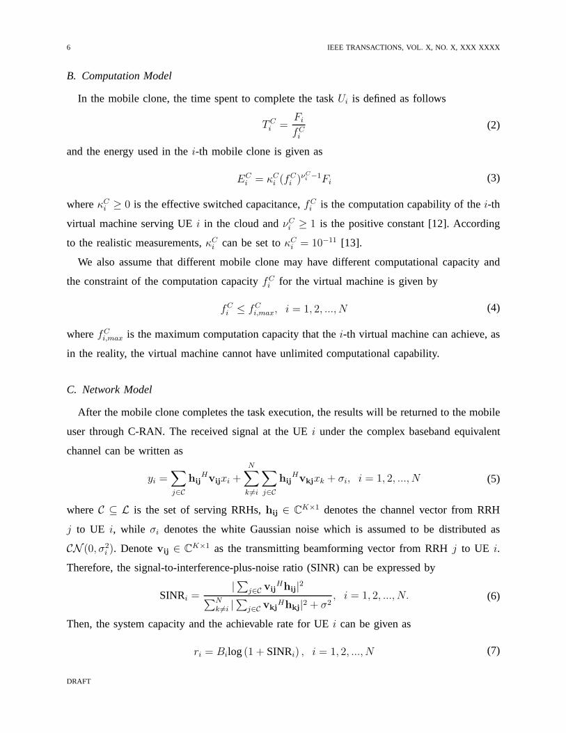
B. Computation Model
In the mobile clone, the time spent to complete the taskUi is defined as follows
TCi =
Fi
fCi
(2)
and the energy used in thei-th mobile clone is given as
ECi = κC
i (fCi )
νCi −1Fi (3)
whereκCi ≥ 0 is the effective switched capacitance,fC
i is the computation capability of thei-th
virtual machine serving UEi in the cloud andνCi ≥ 1 is the positive constant [12]. According
to the realistic measurements,κCi can be set toκC
i = 10−11 [13].
We also assume that different mobile clone may have different computational capacity and
the constraint of the computation capacityfCi for the virtual machine is given by
fCi ≤ fC
i,max, i = 1, 2, ..., N (4)
wherefCi,max is the maximum computation capacity that thei-th virtual machine can achieve, as
in the reality, the virtual machine cannot have unlimited computational capability.
C. Network Model
After the mobile clone completes the task execution, the results will be returned to the mobile
user through C-RAN. The received signal at the UEi under the complex baseband equivalent
channel can be written as
yi =∑
j∈C
hijHvijxi +
N∑
k 6=i
∑
j∈C
hijHvkjxk + σi, i = 1, 2, ..., N (5)
whereC ⊆ L is the set of serving RRHs,hij ∈ CK×1 denotes the channel vector from RRH
j to UE i, while σi denotes the white Gaussian noise which is assumed to be distributed as
CN (0, σ2i ). Denotevij ∈ CK×1 as the transmitting beamforming vector from RRHj to UE i.
Therefore, the signal-to-interference-plus-noise ratio(SINR) can be expressed by
SINRi =|∑
j∈C vijHhij|2
∑N
k 6=i |∑
j∈C vkjHhkj|2 + σ2
, i = 1, 2, ..., N. (6)
Then, the system capacity and the achievable rate for UEi can be given as
ri = Bilog(1 + SINRi) , i = 1, 2, ..., N (7)
DRAFT
SHELL et al.: BARE DEMO OF IEEETRAN.CLS FOR JOURNALS 7
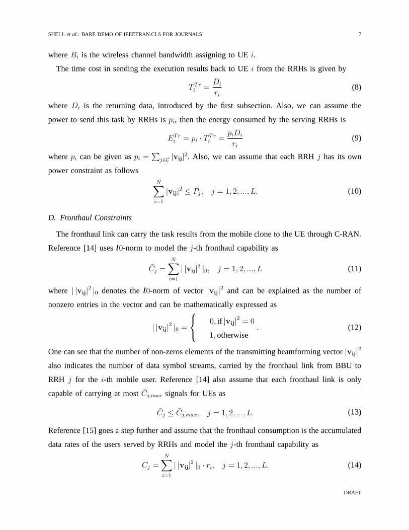
whereBi is the wireless channel bandwidth assigning to UEi.
The time cost in sending the execution results back to UEi from the RRHs is given by
T Tri =
Di
ri(8)
whereDi is the returning data, introduced by the first subsection. Also, we can assume the
power to send this task by RRHs ispi, then the energy consumed by the serving RRHs is
ETri = pi · T
Tri =
piDi
ri(9)
wherepi can be given aspi =∑
j∈C |vij|2. Also, we can assume that each RRHj has its own
power constraint as followsN∑
i=1
|vij|2 ≤ Pj , j = 1, 2, ..., L. (10)
D. Fronthaul Constraints
The fronthaul link can carry the task results from the mobileclone to the UE through C-RAN.
Reference [14] usesl0-norm to model thej-th fronthaul capability as
C̄j =N∑
i=1
| |vij|2 |0, j = 1, 2, ..., L (11)
where | |vij|2 |0 denotes thel0-norm of vector|vij|
2 and can be explained as the number of
nonzero entries in the vector and can be mathematically expressed as
| |vij|2 |0 =
0, if |vij|2 = 0
1, otherwise. (12)
One can see that the number of non-zeros elements of the transmitting beamforming vector|vij|2
also indicates the number of data symbol streams, carried bythe fronthaul link from BBU to
RRH j for the i-th mobile user. Reference [14] also assume that each fronthaul link is only
capable of carrying at most̄Cj,max signals for UEs as
C̄j ≤ C̄j,max, j = 1, 2, ..., L. (13)
Reference [15] goes a step further and assume that the fronthaul consumption is the accumulated
data rates of the users served by RRHs and model thej-th fronthaul capability as
Cj =
N∑
i=1
| |vij|2 |0 · ri, j = 1, 2, ..., L. (14)
DRAFT

8 IEEE TRANSACTIONS, VOL. X, NO. X, XXX XXXX
In this case, thej-th fronthaul constraint can be modeled as the maximum data rates which can
be allowed to transmitting through BBU toj-th RRH asCj ≤ Cj,max. We also use this fronthaul
constraint in our paper.
E. QoS Requirement
The qualify of service (QoS) can be given as the whole time cost for completing the required
task and returning the results back to the mobile user. We define the total time spent in executing
and transmitting the task results to UEi as
Ti = T Tri + TC
i . (15)
We also assume that the task has to be accomplished in time constraintsTi,max in order to satisfy
the mobile user’s requirement, then the QoS constraint can be given as
Ti ≤ Ti,max (16)
Also, the whole energy cost in executing this task and transiting the results back toi-th UE
can be given as
Ei = ECi + ηiE
Tri
(17)
whereηi ≥ 0 is a weight to trade off between the energy consumptions in the mobile cloud and
the C-RAN, and it can be also explained as the inefficiency coefficient of the power amplifier
at RRH.
III. PROBLEM FORMULATION AND SEPARATE SOLUTIONS
In this section, we provide the energy minimization problemformulation. Our design aims to
minimize the energy cost while satisfying the time constraints. First, we formulate the energy
minimization for the mobile clone and then we give the energyminimization formulation for
C-RAN with the fronthaul constraints. Two separate solutions are also provided for the energy
minimization to the mobile clone and C-RAN, respectively.
DRAFT
SHELL et al.: BARE DEMO OF IEEETRAN.CLS FOR JOURNALS 9
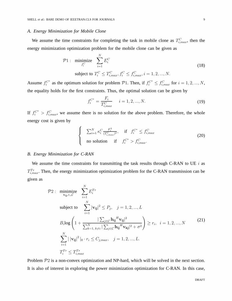
A. Energy Minimization for Mobile Clone
We assume the time constraints for completing the task in mobile clone asTCi,max, then the
energy minimization optimization problem for the mobile clone can be given as
P1 : minimizefCi
N∑
i=1
ECi
subject toTCi ≤ TC
i,max, fCi ≤ fC
i,max, i = 1, 2, ..., N.
(18)
AssumefC∗
i as the optimum solution for problemP1. Then, if fC∗
i ≤ fCi,max for i = 1, 2, ..., N ,
the equality holds for the first constraints. Thus, the optimal solution can be given by
fC∗
i =Fi
TCi,max
i = 1, 2, ..., N. (19)
If fC∗
i > fCi,max, we assume there is no solution for the above problem. Therefore, the whole
energy cost is given by
∑N
i=1 κCi
F 3i
(TCi,max)
2 , if fC∗
i ≤ fCi,max
no solution if fC∗
i > fCi,max.
(20)
B. Energy Minimization for C-RAN
We assume the time constraints for transmitting the task results through C-RAN to UEi as
T Tri,max. Then, the energy minimization optimization problem for the C-RAN transmission can be
given as
P2 : minimizevij,ri,C
N∑
i=1
ETri
subject toN∑
i=1
|vij|2 ≤ Pj, j = 1, 2, ..., L
Bilog
(
1 +|∑
j∈C hijHvij|
2
∑N
k=1, k 6=i |∑
j∈C hijHvkj|2 + σ2
)
≥ ri, i = 1, 2, ..., N
N∑
i=1
| |vij|2 |0 · ri ≤ Cj,max, j = 1, 2, ..., L.
T Tri ≤ T Tr
i,max
(21)
ProblemP2 is a non-convex optimization and NP-hard, which will be solved in the next section.
It is also of interest in exploring the power minimization optimization for C-RAN. In this case,
DRAFT

10 IEEE TRANSACTIONS, VOL. X, NO. X, XXX XXXX
the equality holds for the last constraints ofP2 and then, the minimum transmission data rate
can be given by
ri ≥Di
T Tri,max
. (22)
Therefore, the power minimization optimization can be written as
P3 : minimizevij,ri,C
N∑
i=1
∑
j∈C
|vij|2
subject toN∑
i=1
|vij|2 ≤ Pj , j = 1, 2, ..., L
Bilog
(
1 +|∑
j∈C hijHvij|2
∑N
k=1, k 6=i |∑
j∈C hijHvkj|2 + σ2
)
≥Di
T Tri,max
, i = 1, 2, ..., N
N∑
i=1
| |vij|2 |0 · ri ≤ Cj,max, j = 1, 2, ..., L.
(23)
As the arbitrary phase rotation of the beamforming vectorsvij does not affectP3, the second
constraint ofP3 can be rewritten as a second-order cone (SOC) constraint as [16]
√
1−1
2Di
Bi·TTri,max
√
√
√
√
N∑
k=1
|∑
j∈C
hijHvkj|2 + σ2 ≤ Re
(
|∑
j∈C
hijHvij|
2
)
, i = 1, 2, ..., N. (24)
Also, according to [17], the non-convexl0-norm can be approximated by a convex reweighted
l1-norm as|V|0 =∑N
k=1 ρk|vk|, wherevk is the k-th element of the vectorV and ρk is the
corresponding weight. Following reference [15], the last constraint inP3 can be rewritten as
follows
Cj =N∑
i=1
ρij |vij|2 · ri ≤ Cj,max, j = 1, 2, ..., L (25)
where
ρij =1
|vij|2 + ǫ
j = 1, 2, ..., L. (26)
DRAFT
SHELL et al.: BARE DEMO OF IEEETRAN.CLS FOR JOURNALS 11
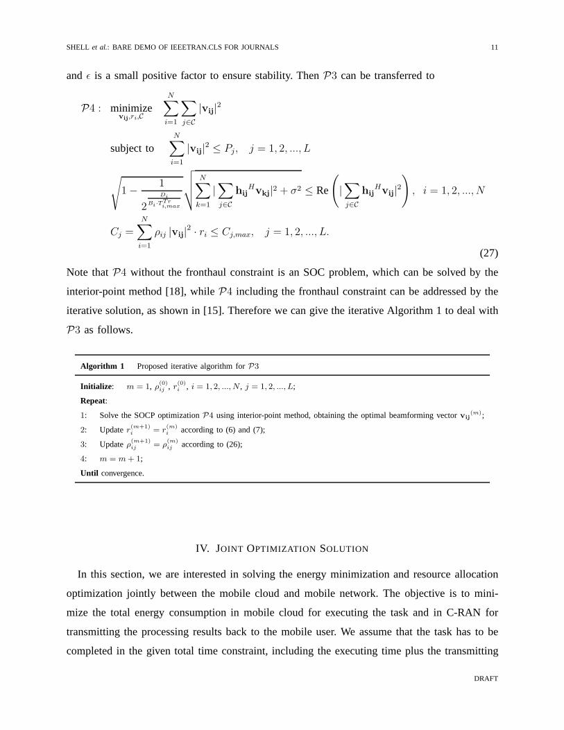
and ǫ is a small positive factor to ensure stability. ThenP3 can be transferred to
P4 : minimizevij,ri,C
N∑
i=1
∑
j∈C
|vij|2
subject toN∑
i=1
|vij|2 ≤ Pj, j = 1, 2, ..., L
√
1−1
2Di
Bi·TTri,max
√
√
√
√
N∑
k=1
|∑
j∈C
hijHvkj|2 + σ2 ≤ Re
(
|∑
j∈C
hijHvij|
2
)
, i = 1, 2, ..., N
Cj =N∑
i=1
ρij |vij|2 · ri ≤ Cj,max, j = 1, 2, ..., L.
(27)
Note thatP4 without the fronthaul constraint is an SOC problem, which can be solved by the
interior-point method [18], whileP4 including the fronthaul constraint can be addressed by the
iterative solution, as shown in [15]. Therefore we can give the iterative Algorithm 1 to deal with
P3 as follows.
Algorithm 1 Proposed iterative algorithm forP3
Initialize: m = 1, ρ(0)ij , r(0)i , i = 1, 2, ..., N , j = 1, 2, ..., L;
Repeat:
1: Solve the SOCP optimizationP4 using interior-point method, obtaining the optimal beamforming vectorvij(m);
2: Updater(m+1)i = r
(m)i according to (6) and (7);
3: Updateρ(m+1)ij = ρ
(m)ij according to (26);
4: m = m+ 1;
Until convergence.
IV. JOINT OPTIMIZATION SOLUTION
In this section, we are interested in solving the energy minimization and resource allocation
optimization jointly between the mobile cloud and mobile network. The objective is to mini-
mize the total energy consumption in mobile cloud for executing the task and in C-RAN for
transmitting the processing results back to the mobile user. We assume that the task has to be
completed in the given total time constraint, including theexecuting time plus the transmitting
DRAFT

12 IEEE TRANSACTIONS, VOL. X, NO. X, XXX XXXX
time. Therefore, the joint energy optimization problem canbe given as
P5 : minimizefCi ,ri,vij,C
N∑
i=1
ECi + ηiE
Tri
subject to
N∑
i=1
|vij|2 ≤ Pj, j = 1, 2, ..., L,
ri = Bilog
(
1 +|∑
j∈C hijHvij|2
∑N
k=1, k 6=i |∑
j∈C hijHvkj|2 + σ2
)
, i = 1, 2, ..., N,
ri ≥ Ri,min, i = 1, 2, ..., N,
fCi ≤ fC
i,max, i = 1, 2, ..., N,
TCi + T Tr
i ≤ Ti,max, i = 1, 2, ..., N,
N∑
i=1
| |vij|2 |0 · ri ≤ Cj,max, j = 1, 2, ..., L.
(28)
whereRi,min is the minimum achievable rate for UEi, and other constraints inP5 have been
introduced in the last sections. The aboveP5 is non-convex problem and is difficult to solve.
In the next subsections, we will provide the iterative algorithms based on weighted minimum
mean square error (WMMSE) solution to deal with it.
A. Problem Transformation
It is obvious that the equality of the time constraints holdsfor P5 [9] in relaxation. Therefore,
by using (2) and (8), time constraints can be relaxed as
Ti,max = T Tri + TC
i
=Di
ri+
Fi
fCi
.(29)
Then,fCi can be given as
fCi =
Fi
Ti,max −Di
ri
. (30)
Given thatTi,max > 0, fCi > 0 andfC
i ≤ fCi,max, one can get the minimum achievable rate as
ri ≥ Ri,min (31)
DRAFT

SHELL et al.: BARE DEMO OF IEEETRAN.CLS FOR JOURNALS 13
where
Ri,min =Di
Ti,max −Fi
fCi,max
. (32)
By using (30), (31) and (32),P5 can be simplified as
P6 : minimizeri,vij,C
N∑
i=1
κCi
(
Fi
Ti,max −Di
ri
)νCi −1
Fi + ηi
∑
j∈C |vij|2Di
ri
subject to
N∑
i=1
|vij|2 ≤ Pj, j = 1, 2, ..., L,
Bilog
(
1 +|∑
j∈C hijHvij|
2
∑N
k=1, k 6=i |∑
j∈C hijHvkj|2 + σ2
)
≥ Ri,min, i = 1, 2, ..., N,
Cj =N∑
i=1
ρij |vij|2 · ri ≤ Cj,max, j = 1, 2, ..., L.
(33)
Note thatfCi does no longer exist inP6. We denotevj = [v1j,v2j, ...,vNj]
H , hj = [h1j,h2j, ...,hNj]H ,
vi = [vi1,vi2, ...,viC]H , hi = [hi1,hi2, ...,hiC]
H for notation simplification. One can rewriteP6
as
P7 : minimizeri,vij,C
N∑
i=1
αi(ri) + ti
subject to: Constraints of(P6)
(34)
where
αi(ri) = κCi
(
Fi
Ti,max −Di
ri
)νCi −1
Fi, (35)
ti =βi(vi)
ri(36)
and
βi(vi) = ηiviHviDi. (37)
Inspired by the solutions provided in [15], [19], [20],P7 can be rewritten as
P8 : minimizeri,vij,C
N∑
i=1
γi(ri) + βi(vi)
subject to: Constraints of(P6)
(38)
DRAFT

14 IEEE TRANSACTIONS, VOL. X, NO. X, XXX XXXX
where
γi(ri) = αi(ri)− ti · ri, (39)
which can be solved by using iterative solution by updatingti in each iteration, ifri is a constant.
Next, we will use WMMSE-based method to deal with the situation if ri is a variable.
B. WMMSE-based Solution
The WMMSE method is introduced by [21], [22] and use to address the weighted sum rate
problem. One can see that the objective ofP8 is an decreasing function of the mobile user’s
data rateri. Therefore, we can reformulateP8 as an equivalent WMMSE problem and use the
block coordinate descent approach to solve it.
Assume the receive beamforming vector in mobile useri asui ⊆ C1×1, as there is only one
antenna in the UE. Thus, the corresponding MSE at UEi can be given as
ei = E[
(uiyi − xi)(uiyi − xi)H]
=N∑
i=1
uiH(hi
Hvivi
Hhi + σ2
i )ui − 2 Re[
uiHhi
Hvi
]
+ 1.(40)
Then, by fixing all the transmit beamforming vectorvi, the optimal receive beamforming
vector can be give by the well-known MMSE receiver as
ui =(
hiHvi
)
·
(
N∑
k=1
hiHvkvk
Hhi + σ2
i
)−1
. (41)
Next, letting
τi(ei) = γi(−Bi · log(ei)), (42)
one can see thatτi(ei) is a strictly convex function under the constraints ofP8 [15], [21]. Then,
by fixing the transmit beamforming vectorvi and the MMSE receiverui, the corresponding
optimal MSE weightφi can be given by
φi =∂τ(ei)
∂ei=
DiκCi (ν
Ci − 1) log(2)
(
BiFi log(ei)BiTi,max log(ei)+Di log(2)
)νCi
Biei log2(ei)
+Biti
ei log(2).
(43)
Then, by fixing the optimal MSE weightφi and MMSE receiverui, the optimal transmit
beamforming vectorvi can be calculated by solving the following SOCP problem as
P9 : minimizeri,vij,C
N∑
i=1
φi · ei + βi(vi)
subject to: Constraints of(P6).
(44)
DRAFT

SHELL et al.: BARE DEMO OF IEEETRAN.CLS FOR JOURNALS 15
Thus, we can deal with the overall optimization problem withWMMSE-based iterative method
as in Algorithm 2, whereZ(n) =∑N
i=1 αi(r(n)i ) + t
(n)i and ε is a small constant to guarantee
convergence.
Algorithm 2 Proposed iterative algorithm for joint optimization problem
Initialize: n = 1, t(0)i , ρ(0)ij , vij(0), r(0)i , i = 1, 2, ..., N , j = 1, 2, ..., L;
Repeat:
1: Obtain the receive beamforming vectorui(n) according to (41) by fixingvij
(n−1);
2: Obtain the MSE weightφi according to (43) by fixingvij(n−1) andui
(n);
3: Obtain the transmit beamforming vectorvij(n) according to SOCPP9 by fixing φ
(n)i , ui
(n);
4: Updater(n+1)i = r
(n)i according to (6) and (7);
5: Updatet(n+1)i = t
(n)i according to (36);
6: Updateρ(n+1)ij = ρ
(n)ij according to (26);
7: n = n+ 1;
Until |Z(n+1) − Z(n)| < ε
V. SIMULATION RESULTS
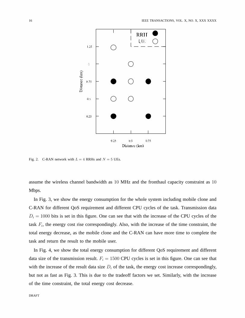
In this section, simulation results are provided to show theeffectiveness of the proposed joint
energy minimization optimization. The simulation environment is shown as Fig. 2, in which we
consider the C-RAN network withL = 4 RRHs, each equipped withK = 2 antennas. Also, we
assume there areN = 5 mobile users, each of which has only one antenna. We assume there
are five mobile clones co-located with the BBUs, and each mobile clone has the same software
stack as its corresponding mobile users and can execute the task for the mobile user.
Moreover, we assume the maximum transmit power for each RRH is 1 W, while the maximum
computation capacity for each mobile clone is106 CPU cycles per second. Similar with [23],
we model the path and penetration loss as
p(d) = 127 + 25log10(d) (45)
whered (km) is the propagation distance. Also, we model the small scale fading as independent
circularly symmetric Gaussian process distributed asCN (0, 1), whereas the noise power spectral
density is assumed to be−100 dBm/Hz. We assume the energy tradeoff factor between the mobile
clone and C-RAN asηi = 10 and the parameter for the cloud energy modelνCi = 2. Also, we
DRAFT
16 IEEE TRANSACTIONS, VOL. X, NO. X, XXX XXXX
Fig. 2. C-RAN network withL = 4 RRHs andN = 5 UEs.
assume the wireless channel bandwidth as10 MHz and the fronthaul capacity constraint as10
Mbps.
In Fig. 3, we show the energy consumption for the whole systemincluding mobile clone and
C-RAN for different QoS requirement and different CPU cycles of the task. Transmission data
Di = 1000 bits is set in this figure. One can see that with the increase ofthe CPU cycles of the
taskFi, the energy cost rise correspondingly. Also, with the increase of the time constraint, the
total energy decrease, as the mobile clone and the C-RAN can have more time to complete the
task and return the result to the mobile user.
In Fig. 4, we show the total energy consumption for differentQoS requirement and different
data size of the transmission result.Fi = 1500 CPU cycles is set in this figure. One can see that
with the increase of the result data sizeDi of the task, the energy cost increase correspondingly,
but not as fast as Fig. 3. This is due to the tradeoff factors weset. Similarly, with the increase
of the time constraint, the total energy cost decrease.
DRAFT

SHELL et al.: BARE DEMO OF IEEETRAN.CLS FOR JOURNALS 17
Fi
1000 1200 1400 1600 1800 2000
Energy(J)
10-1
100
101
102T
i,max=0.1 s
Ti,max
=0.2 s
Ti,max
=0.3 s
Ti,max
=0.4 s
Ti,max
=0.5 s
Fig. 3. Total energy consumption vs. CPU cycles under different Ti,max with Di = 1000.
In Fig. 5, the relations between the total energy consumption and different time constraints
are examined under differentDi with total CPU cyclesFi = 1500. One can see that with the
increase of the time constraints, the energy consumption decreases, as expected. Also, with the
increase of the data size, the energy increases, but the gap between them is small.
Similar with Fig. 5, Fig. 6 shows that the whole energy consumption of mobile cloud and
C-RAN decreases either with the increase of the time constraints or with the decrease of the
CPU cycles required by each task.
In Fig. 7 and Fig. 8, we compare the proposed joint energy minimization optimization with
the separate energy minimization solutions, which has beenused in some works such as [23],
etc. For the separate energy minimization, we set two time constraints asT Tri ≤ T Tr
i,max and
TCi ≤ TC
i,max, whereT Tri,max+TC
i,max = Ti,max. Ti,max = 0.1s is set in both Fig. 7 and Fig. 8 while
Di = 1000 andFi = 1500 are set in Fig. 7 and Fig. 8, respectively. One can see that thejoint
DRAFT

18 IEEE TRANSACTIONS, VOL. X, NO. X, XXX XXXX
Di×104
0 0.5 1 1.5 2 2.5 3 3.5 4 4.5 5
Energy
(J)
10-1
100
101
102
Ti,max
=0.1 s
Ti,max
=0.2 s
Ti,max
=0.3 s
Ti,max
=0.4 s
Ti,max
=0.5 s
Fig. 4. Total energy consumption vs. data size under different Ti,max with Fi = 1500.
energy minimization achieves the best performance, followed by the second best solution when
settingT Tri,max = T Tr
i,max/4 in both Fig. 7 and Fig. 8. The performance ofT Tri,max = T Tr
i,max∗3/4 can
be shown as the worst solution among the test ones in both figures. Therefore, the simulation
results show that the proposed joint energy minimization outperforms the separate solutions in
all the cases.
VI. CONCLUSION
A novel C-RAN architecture with the mobile clone involved isproposed in this paper by
taking full advantages of the two cloud-based techniques. In particular, we assume there is one
task needed to be executed in the mobile clone for each UE and we model this task with two
features, i.e, the total number of the CPU cycles required tocomplete this task and the data size
required to transmit the result back to the UEs through C-RAN. We jointly minimize the whole
DRAFT

SHELL et al.: BARE DEMO OF IEEETRAN.CLS FOR JOURNALS 19
Ti(s)0.1 0.2 0.3 0.4 0.5 0.6 0.7 0.8 0.9 1
Energy
(J)
10-1
100
101
102
Di=50000
Di=60000
Di=70000
Di=80000
Di=90000
Fig. 5. Total energy consumption vs. time constraint under different data sizeDi with Fi = 1500.
energy cost in mobile cloud and mobile network by modeling this problem into the optimization
problem when taking the time constraints into consideration. Also, we consider the fronthaul
constraints in C-RAN in order to get the sparse solutions. Numerical results are presented to
show that the proposed energy minimization and resource allocation solution can improve the
system performance and save energy.
VII. A CKNOWLEDGEMENT
This work was supported by UK EPSRC NIRVANA project (EP/L026031/1) and EU Horizon
2020 iCIRRUS project (GA-644526).
REFERENCES
[1] J. Andrews, S. Buzzi, W. Choi, S. Hanly, A. Lozano, A. Soong, and J. Zhang, “What will 5g be?”IEEE Journal on
Selected Areas in Communications, vol. 32, no. 6, pp. 1065–1082, June 2014.
DRAFT

20 IEEE TRANSACTIONS, VOL. X, NO. X, XXX XXXX
Ti(s)0.1 0.2 0.3 0.4 0.5 0.6 0.7 0.8 0.9 1
Energy
(J)
10-1
100
101
102
Fi=1500
Fi=1750
Fi=2000
Fi=2250
Fi=2500
Fig. 6. Total energy consumption vs. time constraint under different CPU cyclesFi with Di = 1000.
[2] X. Rao and V. Lau, “Distributed fronthaul compression and joint signal recovery in cloud-ran,”IEEE Transactions on
Signal Processing, vol. 63, no. 4, pp. 1056–1065, Feb 2015.
[3] C. M. R. Institute., “C-ran white paper: The road towardsgreen ran. [online],” (Jun. 2014), Available:
http://labs.chinamobile. com/cran.
[4] S. Kosta, A. Aucinas, P. Hui, R. Mortier, and X. Zhang, “Thinkair: Dynamic resource allocation and parallel execution in
the cloud for mobile code offloading,” in2012 IEEE Proceedings INFOCOM, March 2012, pp. 945–953.
[5] K. Kumar and Y.-H. Lu, “Cloud computing for mobile users:Can offloading computation save energy?”Computer, vol. 43,
no. 4, pp. 51–56, April 2010.
[6] W. Zhang, Y. Wen, K. Guan, D. Kilper, H. Luo, and D. Wu, “Energy-optimal mobile cloud computing under stochastic
wireless channel,”IEEE Transactions on Wireless Communications, vol. 12, no. 9, pp. 4569–4581, September 2013.
[7] X. Chen, “Decentralized computation offloading game formobile cloud computing,”IEEE Transactions on Parallel and
Distributed Systems, vol. 26, no. 4, pp. 974–983, April 2015.
[8] Y. Cai, F. Yu, and S. Bu, “Cloud radio access networks (c-ran) in mobile cloud computing systems,” in2014 IEEE
Conference on Computer Communications Workshops (INFOCOM WKSHPS), April 2014, pp. 369–374.
[9] J. Tang, W. P. Tay, and T. Quek, “Cross-layer resource allocation in cloud radio access network,” in2014 IEEE Global
DRAFT

SHELL et al.: BARE DEMO OF IEEETRAN.CLS FOR JOURNALS 21
Fi
1000 1100 1200 1300 1400 1500 1600 1700 1800 1900 2000
Energy
(J)
100
101
102
103
Joint optimization
Ti,maxTr =T
i,max/4
Ti,maxTr =T
i,max/2
Ti,maxTr =T
i,max*3/4
Fig. 7. Total energy consumption vs. CPU cycles under different T Tri,max with Di = 1000.
Conference on Signal and Information Processing (GlobalSIP), Dec 2014, pp. 158–162.
[10] M. Guazzone, C. Anglano, and M. Canonico, “Energy-efficient resource management for cloud computing infrastructures,”
in 2011 IEEE Third International Conference on Cloud Computing Technology and Science (CloudCom), Nov 2011, pp.
424–431.
[11] L. Yang, J. Cao, S. Tang, T. Li, and A. Chan, “A framework for partitioning and execution of data stream applications
in mobile cloud computing,” in2012 IEEE 5th International Conference on Cloud Computing (CLOUD), June 2012, pp.
794–802.
[12] J. Tang, W. P. Tay, and Y. Wen, “Dynamic request redirection and elastic service scaling in cloud-centric media networks,”
IEEE Transactions on Multimedia, vol. 16, no. 5, pp. 1434–1445, Aug 2014.
[13] A. P. Miettinen and J. K. Nurminen, “Energy efficiency ofmobile clients in cloud computing,” inProceedings of the 2nd
USENIX conference on Hot topics in cloud computing, 2010, p. 4.
[14] V. N. Ha and L. B. Le, “Joint coordinated beamforming andadmission control for fronthaul constrained cloud-rans,”in
2014 IEEE Global Communications Conference (GLOBECOM), Dec 2014, pp. 4054–4059.
[15] B. Dai and W. Yu, “Sparse beamforming and user-centric clustering for downlink cloud radio access network,”IEEE
Access, vol. 2, pp. 1326–1339, 2014.
DRAFT

22 IEEE TRANSACTIONS, VOL. X, NO. X, XXX XXXX
Di ×1040 0.5 1 1.5 2 2.5 3 3.5 4 4.5 5
Energy
(J)
101
102
103
Joint optimizationT
i,maxTr =T
i,max/4
Ti,maxTr =T
i,max/2
Ti,maxTr =T
i,max*3/4
Fig. 8. Total energy consumption vs. data size under different T Tri,max with Fi = 1500.
[16] A. Wiesel, Y. Eldar, and S. Shamai, “Linear precoding via conic optimization for fixed mimo receivers,”IEEE Transactions
on Signal Processing, vol. 54, no. 1, pp. 161–176, Jan 2006.
[17] E. J. Candes, M. B. Wakin, and S. P. Boyd, “Enhancing sparsity by reweighted l1 minimization,”Journal of Fourier
Analysis and Applications, vol. 14, no. 5-6, pp. 877–905, 2008.
[18] S. Boyd and L. Vandenberghe,Convex Optimization. Cambridge University Press, 2004.
[19] W. Dinkelbach, “On nonlinear fractional programming,” Manag. Science, vol. 13, pp. 492–498, 1967.
[20] M. Peng, K. Zhang, J. Jiang, J. Wang, and W. Wang, “Energy-efficient resource assignment and power allocation in
heterogeneous cloud radio access networks,”IEEE Transactions on Vehicular Technology, vol. PP, no. 99, pp. 1–1, 2014.
[21] Q. Shi, M. Razaviyayn, Z.-Q. Luo, and C. He, “An iteratively weighted mmse approach to distributed sum-utility
maximization for a mimo interfering broadcast channel,”IEEE Transactions on Signal Processing, vol. 59, no. 9, pp.
4331–4340, Sept 2011.
[22] S. Christensen, R. Agarwal, E. Carvalho, and J. Cioffi, “Weighted sum-rate maximization using weighted mmse for mimo-bc
beamforming design,”IEEE Transactions on Wireless Communications, vol. 7, no. 12, pp. 4792–4799, December 2008.
[23] Y. Shi, J. Zhang, and K. Letaief, “Group sparse beamforming for green cloud radio access networks,” in2013 IEEE Global
Communications Conference (GLOBECOM),, Dec 2013, pp. 4662–4667.
DRAFT