ieee transactions on wireless communications, vol. …
TRANSCRIPT

1536-1276 (c) 2013 IEEE. Personal use is permitted, but republication/redistribution requires IEEE permission. Seehttp://www.ieee.org/publications_standards/publications/rights/index.html for more information.
This article has been accepted for publication in a future issue of this journal, but has not been fully edited. Content may change prior to final publication. Citation information: DOI10.1109/TWC.2014.2364179, IEEE Transactions on Wireless Communications
IEEE TRANSACTIONS ON WIRELESS COMMUNICATIONS, VOL. XX, NO. X, 2014 1
Seamless Handover for High-Speed Trains UsingFemtocell-based Multiple Egress Network Interfaces
Cheng-Wei Lee, Ming-Chin Chuang, Meng Chang Chen, and Yeali S. Sun
Abstract—High-speed rail systems are becoming increasinglypopular among long-distance travelers. With the explosive growthin the number of mobile devices, the provision of high qualitytelecommunication and Internet access services on high-speedtrains is now a pressing problem. Network mobility (NEMO)has been proposed to enable a large number of mobile deviceson a vehicle to access the Internet; however, several issuesmust be solved before it can be put into practice, e.g., frequenthandovers, long handover latency, and poor quality of service. Toresolve the above problems, we propose an LTE femtocell-basednetwork mobility scheme that uses Multiple Egress Networkinterfaces to support seamless handover for high-speed railsystems, called MEN-NEMO. The results of simulations show thatthe proposed MEN-NEMO scheme reduces the handover latencyand transmission overhead of handover signaling substantially.
Index Terms—Network mobility, high-speed train, signalingexplosion, multiple network interfaces, seamless handover
I. INTRODUCTION
H IGH-speed rail systems are becoming increasingly pop-ular among long-distance travelers because they have a
number of advantages over air travel. The advantages includelower operating costs, lower fares, a more comfortable travelexperience, less likelihood of weather disruptions, and lowerenergy consumption. With the explosive growth in the numberof mobile devices, the provision of high quality telecom-munication and Internet access services on high-speed trainsis now a pressing problem. However, to satisfy passengerrequirements in such high-speed environments, a number ofchallenges must be overcome, e.g., frequent handovers, si-multaneous mass handovers, insufficient bandwidth, and poorquality of service [1].
The mass handover problem occurs when mobile devicesperform handover from one base station (BS) to anotherBS simultaneously. This creates a signaling message stormand generates a large number of processing demands on thewireless link and the network components of the infrastructure.Network mobility (NEMO) [2] has been proposed to facilitatevehicle-to-infrastructure communications. It refers to the mo-bility of a network of communication devices (called a mobilenetwork) that changes its attachment points to the Internet as
Manuscript received September 27, 2013, revised April 19 and September23, 2014, accepted October 11, 2014.
Cheng-Wei Lee is with the Research Center for Information TechnologyInnovation, Academia Sinica, Taiwan, e-mail: [email protected].
Ming-Chin Chuang is with the Institute of Information Science, AcademiaSinica, Taiwan, E-mail: [email protected].
Meng-Chang Chen is with the Institute of Information Science, AcademiaSinica, Taiwan, E-mail: [email protected].
Yeali S. Sun is with the Department of Information Management, NationalTaiwan University, Taiwan, E-mail: [email protected].
one entity. All packets are transmitted over the Internet viadesignated mobile routers (MRs). The communication devices,called mobile network nodes (MNNs) or user equipment (UE),connect to the MR via, for example, Ethernet, WiFi or fem-tocell BSs. An MRs antenna is mounted outside the carriage,thereby solving the carriage penetration problem. To deal withthe serious Doppler shift problem and rapid landscape changes,the MR is equipped with advanced hardware and software,such as MIMO and sophisticated signal processing techniques.In high-speed rail environment, the power consumption is not aconcern because devices can be recharged. As a result, networkmobility reduces the complexity of the hardware and softwareof MNNs. It also benefits network operators by reducingthe processing and signaling overheads for authentication,authorization, accounting, and network resource management.
Choosing a wireless access technology for the train-to-ground link (i.e., communications between the high-speed trainand the roadside eNB) is the first issue that must be addressedwhen implementing a network mobility scheme on high-speedrail systems. Cellular-based solutions are generating moreinterest than satellite Internet services because they supportnon-line-of-sight propagation, higher data rates and lowercommunication latency at less cost. Advanced standards, suchas 3GPP LTE-A [24], have low handover latency and providea data rate between 300Mbps and 1Gps on the downlink.In addition, the physical layer supports robust wireless linkadaptation at speeds between 250 and 360 km/h. However,the small coverage radius of the base stations results in morefrequent handovers. For instance, given a cell radius of 5km, mobile devices on a high-speed train traveling at 360km/h would experience handover every 50 seconds. Moreover,the large movement area of a high-speed train increases thelikelihood of IP change, causing extra handover delay andpacket loss.
A major disadvantage of using a single egress network inter-face is that, the user equipment (UE) suffers from a transienttransmission disruption during handover; and this problembecomes more serious as the handover frequency increases.As an alternative, multiple interfaces (including multiple MRs)were used initially to fully utilize the wireless link diversity(a.k.a., antenna diversity) and thereby improve the link quality.Recently, multiple interfaces have been proposed to coordinateand facilitate seamless handover. In this paper, we focus onseamless handover for high-speed trains and propose a networkmobility protocol with multiple egress network interfaces,called MEN-NEMO.
The remainder of this paper is organized as follows. SectionII provides a review of related works on network mobility

1536-1276 (c) 2013 IEEE. Personal use is permitted, but republication/redistribution requires IEEE permission. Seehttp://www.ieee.org/publications_standards/publications/rights/index.html for more information.
This article has been accepted for publication in a future issue of this journal, but has not been fully edited. Content may change prior to final publication. Citation information: DOI10.1109/TWC.2014.2364179, IEEE Transactions on Wireless Communications
IEEE TRANSACTIONS ON WIRELESS COMMUNICATIONS, VOL. XX, NO. X, 2014 2
design and multiple egress network interfaces. In Section III,we describe the operations of the proposed mechanism; andin Section IV, we analyze its performance. Section V containssome concluding remarks.
II. RELATED WORK
A. Network Mobility Design
A number of solutions have been proposed for networkmobility on different protocol layers. In general, higher levelmobility management requires less infrastructural support,but it entails end-system support, additional signaling andan encapsulation overhead. In contrast, lower level mobilitymanagement provides more efficient signaling and handoveroperations; and it requires less involvement of end-systems byintroducing heavy infrastructure dependency [5].
SIP-NEMO [6] and SIP-NMG [7] are designed for Ses-sion Initial Protocol (SIP)-based applications. The MR onthe vehicle translates SIP signaling for the MNN. HarMoNy[5] integrates the Host Identity Protocol (HIP) with MobileIPv6 by exploiting HIP-enabled MNNs. The above protocolsare designed for specific applications or they require newfunctionality on the MNNs, which is a disadvantage in widelydeployed applications. The network mobility basic supportprotocol [8], which establishes a bi-directional tunnel betweenthe MR and its home agent, provides mobility transparencyfor the MNNs and allows them to use native applicationswithout modification. However, in the context of high-speedrail systems, more advanced wireless access technology shouldbe adopted to provide better signal quality; and more efficienthandover mechanisms are required to ensure un-interruptedcommunications.
B. Multiple Egress Network Interfaces
Multiple egress network interfaces improve the link qualityand handover performance of mobile devices in vehicles. Forexample, the Mobile Access Router (MAR) infrastructure [9]integrates multiple wireless access technologies and exploitsnetwork diversity to provide a high quality communicationchannel for MNNs. However, a single egress network interfacefor each wireless access technology is still not sufficientlyrobust or reliable [3]. In this paper, we use equivalent egressnetwork interfaces to share the communication load and per-form handovers cooperatively.
Our previous work [3] takes advantage of a trains lengthto deploy multiple MRs in WiMAX networks. A networkmobility management protocol is designed on the IPv6 net-work. An egress network interface in the head carriage andanother one in the tail carriage perform handover alternatelyand transmit the data traffic of the mobile network. The schemeprovides seamless handover for the MNNs on a high-speedtrain. Later, Tian et al. [4] also utilize the same concept as[3] and implement the MR by using LTE relay stations. Thisarchitecture is called Train Relay Station (TRS) and it requiresthe transfer of all the information (e.g., the identities) aboutthe active UEs on the train (i.e., the MNNs) when performinghandover. The TRS handover protocol employs bi-casting fromthe serving gateway (S-GW) to the serving evolved Node B
(eNB) and the target eNB during handover. The objective isto eliminate the data forwarding delay between the servingeNB and the target eNB. A femtocell-based network mobil-ity solution and handover scheme is proposed in [10]. Thefemtocell provides IP-based encapsulation communications forthe MNNs so that only the femtocell BSs information hasto be transferred and processed when performing handover.However, the authors of [10] do not provide details aboutthe signaling and configuration. Moreover, the femtocell oneach carriage works independently without utilizing the linkdiversity to improve the signal quality, and it also does notconsider the effect of the overlapping area.
C. Information Raining
Huang et al. [21] proposed an antenna assignment algorithmfor maximum ratio combining. Moreover, this algorithm canalso be applied to the information raining system. Sue etal. [22] proposed the network coding scheme for improvingthe performance of the high-speed train in IEEE 802.16relay networks. Ho and Valaee [23] designed a novel systemarchitecture that enables high-speed Internet access in railwaysystems. In addition, they used packet fragment and repeaterrelay schemes to enhance the system throughput. The goalsof these studies [21-23] focus on high throughput in a high-speed train environment without taking handover problem intoaccount, while this paper focuses on the handover procedureto allow low handover latency, low packet loss and signalingoverhead.
III. THE PROPOSED SCHEME
Next, we present the system architecture of the networkmobility (NEMO) protocol for high-speed trains. It is basedon LTE femtocell technology with multiple egress networkinterfaces. We solved the routing optimization and IP mobilityissues of NEMO and nested NEMO in our previous works [3][18] [19]. We used the pre-handover mechanism to reduce thehandover latency and provided a buffer management mecha-nism to resolve the packet loss problem in NEMO. Moreover,we adopted the ad hoc routing scheme to achieve the routingoptimization of transmission path in nested NEMO. In thispaper, we focus on the seamless handover procedure betweenthe serving eNB and the target eNB.
A. The System/Core Network Architecture
In Fig. 1, an enhanced femtocell base station (called anenhanced HeNB) is deployed on a train to serve the userequipment (UE) on the train (i.e., the MNNs) as an eNB.The Mobility Management Entity (MME) and the ServingGateway (S-GW) handle the UEs mobility events. The MMEU
and S-GWU are responsible for the UEs mobility eventsand packet forwarding, respectively; the MMEf and S-GWf
are responsible for the enhanced HeNBs mobility events andpacket forwarding, respectively. Under the LTE standard, aHeNB connects to the operators core network via a publicnetwork over a secure IP-based connection (e.g., IPsec). Theproposed scheme configures the egress interface(s) of the

1536-1276 (c) 2013 IEEE. Personal use is permitted, but republication/redistribution requires IEEE permission. Seehttp://www.ieee.org/publications_standards/publications/rights/index.html for more information.
This article has been accepted for publication in a future issue of this journal, but has not been fully edited. Content may change prior to final publication. Citation information: DOI10.1109/TWC.2014.2364179, IEEE Transactions on Wireless Communications
IEEE TRANSACTIONS ON WIRELESS COMMUNICATIONS, VOL. XX, NO. X, 2014 3
enhanced HeNB to communicate with the MMEU and S-GWU
via the IP connection in an LTE wireless access network. Inother words, the enhanced HeNBs egress interface acts as a UEthat connects to the serving eNB on the ground and is servedby the MMEf and the S-GWf1. As a result, when a request(e.g., a call) is destined for the UE, it is forwarded from theMMEU /S-GWU to the enhanced HeNB via the S-GWf1 andthe serving eNB. Note that, for clarity, some interfaces (e.g.,between MMEf and the eNB under S-GWf2) are not shownin Fig. 1.
The detailed protocol stacks of the S1-MME control planeand S1-U user plane between the enhanced HeNB and theMMEU and S-GWU [11] are shown in Figs. 2 and 3 re-spectively, including the underlying S1-U user plane. Thecontrol signal and data packets for the UE are IP-encapsulated(and decapsulated) by the enhanced HeNB. Consequently, theMMEf and the S-GWf1 only have to exchange and processthe context of the enhanced HeNB, including the networkresource reservation and admission control. In addition, whenthe enhanced HeNB performs handover from the serving eNBto the target eNB [11], or when the anchor S-GW of theenhanced HeNB is changed from the S-GWf1 to the S-GWf2(i.e., Tracking Area Update) [12], the signal only includesthe information about the enhanced HeNB. Note that if theIP address of the enhanced HeNBs egress network interfaceis changed after handover, the enhanced HeNB should re-register with the MMEU and the S-GWU , as stipulated in [13].The network configuration proposed in this paper does notrequire modification of the 3GPP standard. The performancecan be further improved in some circumstances. For example,if the enhanced HeNB is operated by the same operator asthe eNBs, the connection between the enhanced HeNB andthe MMEU /S-GWU is naturally secured by the lower layerbearers. As the connection does not require extra encryption,the processing, signaling and packet header overheads arereduced. Moreover, if the S-GWf supports direct forwardingto the MMEU and S-GWU without going through the P-GWf ,the transmission delay can be reduced further.
Note that our architecture is compatible with the 3GPPstandard. Therefore, the security functionality of the 3GPP
Fig. 1. The proposed system architecture
Fig. 2. The S1-MME control plane over the S1-U user plane
Fig. 3. The S1-U user plane over the S1-U user plane
standard can be applied directly in our architecture. In thearchitecture, the high-speed train acts as a big mobile de-vice with multiple distributed antennas. The MNN performsthe security operations (e.g., authentication, registration, etc.)when it connects to the Internet through the enhanced HeNB inthe first time, which will keep the security information of theMNN. Afterward, the enhanced HeNB performs the securityoperations on behalf of MNNs until the MNN leaves the high-speed train.
B. The Network Architecture on a Train
Figure 4 illustrates the proposed network architecture fora high-speed train. The architecture, which is a modifiedversion of that presented in [3], uses an enhanced HeNBto implement the MR. The UE on the train attaches to theenhanced HeNB via the access point in the carriage. Wiredand wireless access technologies like Ethernet, WiFi, 2Gor 3G can also be adopted to provide data communicationand telecommunication services to the MNNs. The enhancedHeNBs egress interface has two antennas, one deployed on thehead carriage and one on the tail carriage to ensure good signalquality and support seamless handover. The egress interface isallocated one IP address, which is used by the enhanced HeNBto connect to the MMEU and the S-GWU . The MMEf , S-GWf and P-GWf recognize the enhanced HeNB by its ID(e.g., the IMSI or the TMSI) and tunnel its data to the servingeNB (according to the eNB ID). The approaches in [3] and[4] utilize the same framework for seamless handover on high-speed trains. The enhanced HeNB continuously monitors thecommunication conditions of the head antenna for handoverdecisions.
When a pre-defined condition is reached, such as thesignal strength threshold, the enhanced HeNB uses the headantenna to perform handover to the target eNB; meanwhile,it transmits uplink and downlink traffic via the tail antenna,which is still attached to the serving eNB. After the enhanced

1536-1276 (c) 2013 IEEE. Personal use is permitted, but republication/redistribution requires IEEE permission. Seehttp://www.ieee.org/publications_standards/publications/rights/index.html for more information.
This article has been accepted for publication in a future issue of this journal, but has not been fully edited. Content may change prior to final publication. Citation information: DOI10.1109/TWC.2014.2364179, IEEE Transactions on Wireless Communications
IEEE TRANSACTIONS ON WIRELESS COMMUNICATIONS, VOL. XX, NO. X, 2014 4
Fig. 4. The multiple egress network interfaces on a train with ten carriages
HeNB completes the handover, the uplink and downlink traffictransmissions are seamlessly transferred to the head antennavia the target eNB (i.e., the new serving eNB). On a 300 meterhigh-speed train traveling at 360km/h, it takes about 3 secondsfor the tail antenna to reach the same handover condition as thehead antenna. That is sufficient time for the enhanced HeNBto complete handover by using the head antenna.
As a result, the UEs communications are not interruptedduring handover. Even if handover using the head antennafails, the enhanced HeNB will use the tail antenna to performhandover again. The head antenna or the tail antenna performsthe handover procedure successfully, and then the communi-cations of MNNs will not be interrupted. Next, we describethe seamless handover procedure in detail.
C. Seamless Handover ProcedureThe design of the seamless intra-MME/S-GW handover
procedure of MEN-NEMO is based on the 3GPP specification[11]. In addition, the movement trajectory of the train is fixedin high-speed rail environment. Therefore, target eNBs can beknown in advance even if the signal strength measurementsare very noisy. Figure 5 shows the detailed handover signalingdiagram. The steps are described as follows.
1) The enhanced HeNB periodically sends a MeasurementReport to the serving eNB. The report contains signalinginformation, such as the received signal strength indication(RSSI) of the head antenna for handover decisions.
2) The serving eNB prepares to perform the handoverprocedure when it receives the RSSI report of the targeteNB from the head antenna. Based on the information inthe Measurment Report and Radio Resource Management(RRM), the serving eNB makes decisions about handoff to theenhanced HeNB. We discuss the detailed handover decisionpolicy in the next subsection.
3) The serving eNB issues a Handover Request with thenecessary information to prepare for handover to the targeteNB, and Admission Control is used to increase the likelihoodof a successful handover. The target eNB replies to the servingeNB with a Handover Request Acknowledgement message toconfirm the handover.
4) The serving eNB sends an Radio Resource Control(RRC) Connection Reconfiguration to the enhanced HeNB.The message contains the channel access parameters that canbe used to attach to the target eNB.
Fig. 5. The proposed handover procedure
5) When the enhanced HeNB receives the RRC ConnectionReconfiguration, it synchronizes with the target eNB and usesthe head antenna to access the target cell. After the headantenna is attached to the target eNB, the enhanced HeNBforwards uplink traffic to the target eNB via the head antenna.Meanwhile, the serving eNB continues sending packets tothe enhanced HeNB via the tail antenna, and the SN StatusTransfer is cancelled.
6) The target eNB sends a Path Switch Request to theMMEf to inform it that the enhanced HeNB has changed toa different cell.
7) The MMEf sends a Modify Bearer Request with thetarget eNBs ID to the S-GWf .
8) The S-GWf switches the downlink data path to the targetside. As a result, the downlink packets are now forwarded tothe enhanced HeNB via the target eNB and the head antenna.
From steps 9) to 11), the Modify Bearer Response, PathSwitch Request Acknowledgement and UE Context Releasemessages are identical to the standard. Finally, in step 12) theserving eNB releases the unused resource.
In the MEN-NEMO scheme, the S-GWf switches the for-warding tunnel end-point for downlink traffic from the servingeNB to the target eNB once the head antenna has attached tothe target eNB. This step does not involve extra bandwidthusage. The signaling delay between the target eNB and theS-GWf and the one-way delay in the opposite direction arenegligible and do not affect the handover performance. Thisis because the signaling delay is completely overlaid by thepacket transmission time of head and tail antennas.
In the standard, each UE only uses a single wirelessinterface to connect to eNB and individually and independentlyperforms the handover procedure. This handover procedure ofthe standard will cause longer handover latency and higherhandover signaling overhead. The main difference betweenstandard and our scheme is from steps 5 to 8. In MEN-NEMO,the communications is not disrupted during handover sincethere are multiple distributed antennas on the train. The tailantenna still receives the packets from the serving eNB whenthe head antenna performs the handover procedure with the

1536-1276 (c) 2013 IEEE. Personal use is permitted, but republication/redistribution requires IEEE permission. Seehttp://www.ieee.org/publications_standards/publications/rights/index.html for more information.
This article has been accepted for publication in a future issue of this journal, but has not been fully edited. Content may change prior to final publication. Citation information: DOI10.1109/TWC.2014.2364179, IEEE Transactions on Wireless Communications
IEEE TRANSACTIONS ON WIRELESS COMMUNICATIONS, VOL. XX, NO. X, 2014 5
target eNB. One difference between the MEN-NEMO schemeand TRS [4] is that the latter employs bi-casting, whichrequires additional network resources to handle redundanttraffic. The amount of traffic may be large for all the UEson the train.
D. Discussion of Handover Failure
We discuss how the tail antenna will handle the handoverfailure of the head antenna situation. Basically, the headantenna repeatedly performs the handover procedure until thehandover procedure of the head antenna is successful. At thismoment in time, the tail antenna still connects to the servingeNB. In the worst case, the tail antenna takes over the handoverprocedure of the head antenna, when the tail antenna will handout the coverage of the serving eNB and the head antenna stillcannot connect to the target eNB.
The real handover failure is happened when the head and tailantennas both execute the handover procedure unsuccessfully.When the noise is low, Tian et al. [4] showed in the section 4that it can be ignored. It says that 1) inter-carrier interference(ICI) and noise component could be averaged out and haveno effect on the final average signal strength in small-scalefading. 2) Moreover, the probability of the handover failureis very low (i.e., 10−3 to 10−5) when the train equips twoantennas at the speed of 360 km/h. When the noise is loudand causes transmission failure, retransmission can be done inthe proposed scheme.
E. Handover decision policy
In existing works, most handover decision policies are basedon the RSSI variant. The UE (or enhanced HeNB) scans theeNB of the neighbor cell list and usually selects the eNB thathas the best RSSI connection. However, the UE (or enhancedHeNB) could execute unnecessary handover operations (i.e.,extra auto-configuration time for the IP address). This wouldincrease the signaling overhead and the probability of serviceinterruption when the UE (or enhanced HeNB) hands over toa different IP domain.
To prevent unnecessary frequently time-consuming IP re-configuration and reduce potential packet delay and loss, weadd more constraints to the handover decision policy. In Step1 of Fig. 5, the enhanced HeNB sends a Measurement Report,which includes the candidate target eNB(s), to the servingeNB. At that point, the serving eNB checks the RSSI(s) ofthe candidate target eNB(s) and determines if the target eNB(s)and the serving eNB are in the same IP domain. If a candidatetarget eNB has a high RSSI and the same IP domain as theserving eNB, it is chosen first. This is because the enhancedHeNB only has to wait for the path switch time (i.e., Steps 6 to10 in Fig. 5) without an IP change when it performs handoverunder the same IP domain.
IV. PERFORMANCE ANALYSISIn this section, we evaluate the handover latency, user
satisfaction, the total size of handover signaling messages,and packet loss in different schemes. We simulate the perfor-mance of the MEN-NEMO scheme using network simulator
3 (NS3) [17] and compare it with the performance of theLTE-individual and TRS schemes. Each simulation result isthe average of thirty runs. The value of error bar is obtainedfrom a 90% confidence interval.We consider two simulationscenarios, as shown in Figure 6. The first (i.e., Fig. 6(a)) isa simple environment in which the enhanced HeNB is servedunder the same IP domain and does not need to change itsIP address when a handover occurs. By contrast, Fig. 6(b)shows a complex environment in which the target eNB(s)may belong to a different IP domain. Therefore, the enhancedHeNB needs to change its IP address when it hands over to adifferent IP domain. In the simulation setting, we assume thatthe network environment allows line-of-sight communications.Table I shows the key parameters used in the system levelsimulation [20]. In the figures, Sim means the results wereobtained from the simulations, and Ana means the results wereobtained via numerical analysis.
A. Performance MetricsThe performance metrics are summarized as follows.(1) Handover latency: The disruption time is computed from
the time when the train begins the handover procedure fromits serving eNB to the target eNB.
(2) User satisfaction: The satisfaction score function utilizesreward and punishment to evaluate the satisfaction levels ofUEs on a train.
(3) Sizes of handover signaling messages: The size is theamount of handover signaling messages, proportional to thebandwidth consumption.
(4) Packet loss: The total numbers of lost packets iscomputed during the handover procedure. The high handoverfailure probability results in high packet loss and low usersatisfaction.
Fig. 6. Two simulation scenarios: (a) a simple environment (b) a complexenvironment

1536-1276 (c) 2013 IEEE. Personal use is permitted, but republication/redistribution requires IEEE permission. Seehttp://www.ieee.org/publications_standards/publications/rights/index.html for more information.
This article has been accepted for publication in a future issue of this journal, but has not been fully edited. Content may change prior to final publication. Citation information: DOI10.1109/TWC.2014.2364179, IEEE Transactions on Wireless Communications
IEEE TRANSACTIONS ON WIRELESS COMMUNICATIONS, VOL. XX, NO. X, 2014 6
TABLE ISIMULATION PARAMETERS
Parameters ValuesTransmission range of eNB 5 km
Number of active users 100 1000Number of eNBs 20, 40Velocity of train 180-360 (km/h)
Route advertisement interval 500 msCarrier frequency 2 GHz
Number of OFDM symbols /slot 7Multipath Rayleigh fading channel
Length of train 0.3 kmTransmission power 85 dBm ( 316kW)
Shadow fading deviation 6 dBm ( 0.003981W)Number of resource blocks 25
Overlap 0.4 kmBandwidth of subcarrier 15 kHz
Packet generation rate per each active user 10 packets/sPacket size 500 bytes
Auto-configuration time of IP address 25 msSimulation time 600s
Fig. 7. The successful ratio of handover in different overlapping area
B. Discussion of Overlapping Area
First, we discuss the overlapping area between two neighboreNBs, because the overlapping area has a great effect on thesuccessful ratio of the handover procedure. If the handoverprocedure fails, the throughput of the system will decreaseseriously. Figure 7 shows the successful ratio of handover indifferent overlapping area. We can observe that the smalleroverlapping area between two neighbor eNBs could sufferfrom the handover failure. Moreover, the train has lowersuccessful ratio of handover when it is moving at high speedenvironment. In other words, the successful ratio of thehandover is almost 100% when the overlapping area is longenough.
C. Handover Latency
The handover latency is an important indicator of whetherthe designed handover procedure is effective. The LTE-individual method only uses a single wireless interface toconnect to eNB. Therefore, the average handover latency ofthe LTE-individual (i.e., HLidv) can be formulated as follows:
HLidv = (1− Ps idv)× (TRe−entry + TRe−connect)
+Ps idv × (THO idv), (1)
(a)
(b)
Fig. 8. The handover latency in: (a) Scenario 1 (b) Scenario 2
where Ps idv denotes the probability of successful handoverfor each user under the LTE-individual method. THO idv isthe handover time that the LTE-individual method, requiresfor the cell scan, negotiation, registration, link switches andauto-configuration of the IP address. Note that the auto-configuration time of an IP address is zero when the handoveris performed in the same IP domain. TRe−entry is the timethat the UE requires for the re-entry, and TRe−connect is thetime taken to re-establish an UEs connection if the call wasdropped because of a long handover latency. Both the TRSscheme and the MEN-NEMO scheme use multiple antennasscheme to improve the handover procedure. Therefore, theaverage handover latency of the TRS (i.e., HLTRS) and thatof the MEN-NEMO scheme (i.e., HLProposed) are formulatedas follows:HLTRS = HLProposed
= Ps × (THO s)+ (1−Ps)× (TRe−entry +TRe−connect),(2)
where Ps denotes the probability of successful handoverunder the TRS and the MEN-NEMO schemes. THO s isthe handover time under both schemes. It includes the timerequired for link switches and auto-configuration of the IPaddress. The values of Ps idv and Ps are derived by thescheme in [4] (i.e., Ps idv is 0.97 and Ps is 0.999 when thetrains speed is 360 km/h). Moreover, THO s is smaller thanTHO idv . Figure 8(a) shows the handover latency of threeschemes in Scenario 1. The handover delays of the entireschemes are low because the UE/enhanced HeNB does notneed to change its IP address. It is noteworthy that the TRS
1536-1276 (c) 2013 IEEE. Personal use is permitted, but republication/redistribution requires IEEE permission. Seehttp://www.ieee.org/publications_standards/publications/rights/index.html for more information.
This article has been accepted for publication in a future issue of this journal, but has not been fully edited. Content may change prior to final publication. Citation information: DOI10.1109/TWC.2014.2364179, IEEE Transactions on Wireless Communications
IEEE TRANSACTIONS ON WIRELESS COMMUNICATIONS, VOL. XX, NO. X, 2014 7
and MEN-NEMO schemes yield the best results because theyuse multiple antennas to reduce the number of disruptions andachieve seamless handover. Figure 8(b) shows the handoverlatency of three schemes in Scenario 2. The MEN-NEMOscheme outperforms the LTE-individual and the TRS methodsbecause its handover decision policy reduces the number ofunnecessary handover operations. The handover latency of theLTE-individual method increases because the UE only usesa single antenna to perform the handover procedure, whichincludes changing to a new IP address and results in a longerhandover delay.
D. User Satisfaction
We define a satisfaction score to evaluate the satisfactionlevels of UEs on a train. For example, assume there are threeMNNs and, in an LTE-individual handover event, two of theMNNs perform handover successfully and one does not. In thiscase, the satisfaction score of the handover event is 2r-p (i.e.,r is the reward and p is the punishment). On the other hand,under the MEN-NEMO scheme, all the handovers performedby the MNNs are either successful or unsuccessful. Giventhat the number of active users is n, the average satisfactionscore of a user (i.e., an MNN) that employs the LTE-individualmethod can be calculated by binomial formula as follows:1n
∑nk=0 C
nkP
ks idv(1− Ps idv)
n−k[k × r − (n− k)× p],(3)
where k is the number of successful handovers for active usersand is the binomial coefficient. The average satisfaction scoresof users that exploit the TRS and the MEN-NEMO schemesare
1n [Ps × n× r − (1− Ps)× n× p]. (4)
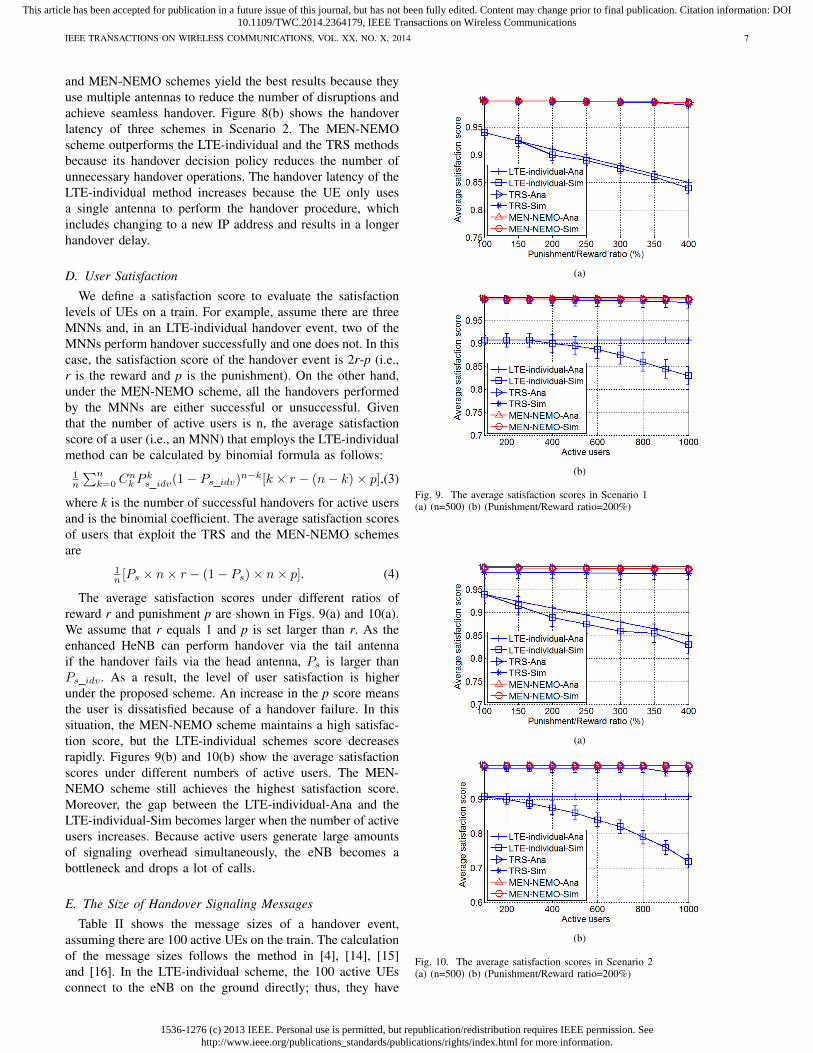
The average satisfaction scores under different ratios ofreward r and punishment p are shown in Figs. 9(a) and 10(a).We assume that r equals 1 and p is set larger than r. As theenhanced HeNB can perform handover via the tail antennaif the handover fails via the head antenna, Ps is larger thanPs idv . As a result, the level of user satisfaction is higherunder the proposed scheme. An increase in the p score meansthe user is dissatisfied because of a handover failure. In thissituation, the MEN-NEMO scheme maintains a high satisfac-tion score, but the LTE-individual schemes score decreasesrapidly. Figures 9(b) and 10(b) show the average satisfactionscores under different numbers of active users. The MEN-NEMO scheme still achieves the highest satisfaction score.Moreover, the gap between the LTE-individual-Ana and theLTE-individual-Sim becomes larger when the number of activeusers increases. Because active users generate large amountsof signaling overhead simultaneously, the eNB becomes abottleneck and drops a lot of calls.
E. The Size of Handover Signaling Messages
Table II shows the message sizes of a handover event,assuming there are 100 active UEs on the train. The calculationof the message sizes follows the method in [4], [14], [15]and [16]. In the LTE-individual scheme, the 100 active UEsconnect to the eNB on the ground directly; thus, they have
(a)
(b)
Fig. 9. The average satisfaction scores in Scenario 1(a) (n=500) (b) (Punishment/Reward ratio=200%)
(a)
(b)
Fig. 10. The average satisfaction scores in Scenario 2(a) (n=500) (b) (Punishment/Reward ratio=200%)

1536-1276 (c) 2013 IEEE. Personal use is permitted, but republication/redistribution requires IEEE permission. Seehttp://www.ieee.org/publications_standards/publications/rights/index.html for more information.
This article has been accepted for publication in a future issue of this journal, but has not been fully edited. Content may change prior to final publication. Citation information: DOI10.1109/TWC.2014.2364179, IEEE Transactions on Wireless Communications
IEEE TRANSACTIONS ON WIRELESS COMMUNICATIONS, VOL. XX, NO. X, 2014 8
TABLE IITHE SIZES OF HANDOVER SIGNALING MESSAGES
Signaling Size (Bytes)Methods LTE-individual TRS MEN-NEMO
Measurement Report 4400 44 44Handover Request 24100 15982 241
Handover Request Ack 7000 2713 70RRC Conn. Reconf. 3600 36 36
RRC Conn. Reconf. Complete 900 9 9SN Status Transfer 7300 - -
Path Switch Request 13600 5977 136Path Switch Request Ack 11700 8730 117Modify Bearer Request 16500 4521 165
Modify Bearer Response 8000 4337 80UE Context Release 3000 30 30Bi-casting Request - 2977 -
Bi-casting Request Ack - 3000 -Total 75600 39498 683
to perform handover by themselves. The TRS scheme onlyrequires some messages to contain the TRSs information, suchas the Measurement Report. However, some messages (e.g.,Handover Requests) still include information about all theactive UEs resulting in the message size cannot be compressed.In the proposed scheme, because the enhanced HeNB encap-sulates all the UEs traffic, all messages only need to includethe information about the enhanced HeNB; therefore, the totalmessage size is further reduced.
Figures 11 and 12 illustrate, respectively, the advantagesof using the femtocell-based configuration and the MR. Themain difference between Fig. 11 and Fig. 12 is the signalingoverhead incurred by changing the IP address. Note that theLTE-individual scheme exchanges a large number of signalingmessages to configure the new IP address in Scenario 2. Inthe MEN-NEMO scheme, the enhanced HeNB uses the MRfunction to reduce the signaling overhead. Therefore, the totalmessage size remains low when the number of active usersincreases.
F. Packet Loss
As shown in Figure 13 (a) and (b), MEN-NEMO schemeoutperforms the other schemes in terms of packet losses. TheLTE-individual scheme loses lots of packets because 1) the UEonly uses one interface to perform the handover procedureresulting in higher handover failure probability and 2) thehigher handover latency causes more lost packets. In Scenario2, the lost packets of the LTE-individual scheme increasesobviously since the train may change its IP address andincrease handover latency. However, TRS and MEN-NEMOstill have few lost packets. This results show the advantage ofmultiple antennas scheme on the train.
V. CONCLUSIONS AND FUTURE WORK
The designs of network mobility scheme for high-speed railsystems are differentiated by the train-to-ground wireless ac-cess technologies, the network architecture and infrastructureon the train, the MR design, the impact on end-devices, andthe handover protocol. This paper proposed a LTE femtocell-based network mobility scheme which only requires minor
Fig. 11. The total size of signaling messages with different number of activeusers in Scenario 1
Fig. 12. The total size of signaling messages with different number of activeusers in Scenario 2
(a)
(b)
Fig. 13. The performance of the packet loss

1536-1276 (c) 2013 IEEE. Personal use is permitted, but republication/redistribution requires IEEE permission. Seehttp://www.ieee.org/publications_standards/publications/rights/index.html for more information.
This article has been accepted for publication in a future issue of this journal, but has not been fully edited. Content may change prior to final publication. Citation information: DOI10.1109/TWC.2014.2364179, IEEE Transactions on Wireless Communications
IEEE TRANSACTIONS ON WIRELESS COMMUNICATIONS, VOL. XX, NO. X, 2014 9
modification of the eNB, so it is easy to deploy. Two antennasare mounted on the train, one on the head carriage and anotheron the tail carriage. They alternate the execution of handoversand transmission of the mobile networks traffic. Therefore,the proposed handover protocol provides uninterrupted servicefor the MNNs, which are important for communications onhigh-speed trains. The proposed scheme was evaluated usingsimulation and analysis, and the performance analysis showsthat the MEN-NEMO scheme outperforms the other schemes.Resource management is also an important issue because wire-less spectrum is a finite resource. Therefore, in a future work,we will consider resource management for different types oftraffic (e.g., voice, audio and video traffic) to maximize thesystem utilization in a high-speed train environment.
REFERENCES
[1] D.T. Fokum and V.S. Frost, A Survey on Methods for Broadband InternetAccess on Trains, IEEE Communications Surveys & Tutorials, vol. 12,no. 2, pp. 171-185, Apr. 2010.
[2] T. Ernst and H.-Y. Lach, Network Mobility Support Terminology, IETFRFC 4885, Jul. 2007.
[3] C.-W. Lee, T.-Y. Lee, M. C. Chen and Y. S. Sun, An Integrated NetworkMobility Management and Call Admission Control Scheme for InternetAccess on High-speed Trains, Technical Report TR-IIS-11-004, Instituteof Information Science, Academia Sinica, Jul. 2011.
[4] L. Tian, J. Li, Y. Huang, J. Shi and J. Zhou, Seamless Dual-LinkHandover Scheme in Broadband Wireless Communication Systems forHigh-Speed Rail, IEEE Journal on Selected Areas in Communications(JSAC), vol. 30, no. 4, pp. 708-718, May 2012.
[5] S. Herborn, L. Haslett, R. Boreli and A. Seneviratne, HarMoNy - HIPMobile Networks, Proc. IEEE Vehicular Technology Conference (VTC2006-Spring), pp. 871-875, May 2006.
[6] C.-M. Huang, C.-H. Lee and J.-R. Zheng, A Novel SIP-Based RouteOptimization for Network Mobility, IEEE Journal on Selected Areas inCommunications, vol. 24, no. 9, pp. 1682-1691, Sep. 2006.
[7] Y.-C. Tseng, J.-J. Chen and Y.-L. Cheng, Design and Implementationof a SIP-Based Mobile and Vehicular Wireless Network With PushMechanism, IEEE Transactions on Vehicular Technology, vol. 56, no.6, pp. 3408-3420, Nov. 2007.
[8] V. Devarapalli, R. Wakikawa, A. Petrescu and P. Thubert, NetworkMobility (NEMO) Basic Support Protocol, IETF RFC 3963, Jan. 2005.
[9] P. Rodriguez, R. Chakravorty, J. Chesterfield, I. Pratt and S. Banerjee,MAR: a commuter router infrastructure for the mobile Internet, Proc. In-ternational Conference On Mobile Systems, Applications And Services(MobiSys), pp. 217-230, Jun. 2004.
[10] O.B. Karimi, J. Liu and C. Wang, Seamless Wireless Connectivity forMultimedia Services in High Speed Trains, IEEE Journal on SelectedAreas in Communications(JSAC), vol. 30, no. 4, pp. 729-739, May 2012.
[11] 3GPP TS 36.300: Overall description; Stage 2, V11.2.0, Jun. 2012.[12] 3GPP TS 23.401: General Packet Radio Service (GPRS) enhancements
for Evolved Universal Terrestrial Radio Access Network (E-UTRAN)access, V11.3.0, Sep. 2012.
[13] 3GPP TS 32.593: Home enhanced Node B (HeNB) Operations, Admin-istration, Maintenance and Provisioning (OAM&P); Procedure flows forType 1 interface HeNB to HeNB Management System (HeMS), V11.0.0,Sep. 2011.
[14] 3GPP TS 36.331: Radio Resource Control (RRC); Protocol specification,V11.1.0, Sep. 2012.
[15] 3GPP TS 36.413: S1 Application Protocol (S1AP), V11.1.0, Sep. 2012.[16] 3GPP TS 36.423: X2 application protocol (X2AP), V11.2.0, Sep. 2012.[17] The Network Simulator 3 (NS3), Available: http://www.nsnam.org/.[18] Ming-Chin Chuang and Jeng-Farn Lee, A Lightweight Mutual Authen-
tication Mechanism for Network Mobility in IEEE 802.16e WirelessNetworks, Computer Networks, Vol.55, Issue 16, pp. 3796-3809, Nov.2011.
[19] Ming-Chin Chuang and Jeng-Farn Lee, DRO: Domain-Based RouteOptimization Scheme for Nested Mobile Networks, EURASIP Journalon Wireless Communications and Networking, pp. 1-19, Aug. 2011.
[20] 3GPP, TR 36.814 (V9.0.0), Mar. 2010.[21] D. Huang, P. Fan, and K. B. Letaief, An optimal antenna assignment
strategy for information raining, IEEE Transactions on Wireless Com-munications, vol. 7, no. 4, pp. 1134 - 1139, Apr. 2008.
[22] C. Sue, S. Sorour, Y Yuk, and S. Valaee, Network Coded InformationRaining over High-Speed Rail through IEEE 802.16j,’ IEEE Personal,Indoor, Mobile, Radio Communication Conference (PIMRC), pp. 1138-1142, Sep. 2009.
[23] D. Ho and S. Valaee, Information Raining for Link-Layer Design ofMobile Hotspots, IEEE Trans. on Mobile Computing, vol. 4, no. 3, pp.271-284, May 2005.
[24] 3GPP TR 36.871, Evolved Universal Terrestrial Radio Access (E-UTRA); Downlink Multiple Input Multiple Output (MIMO) enhance-ment for LTE-Advanced, version 11.0.0, Sep. 2012.
Cheng-Wei Lee received the B.S., M.B.A. andPh.D. degree from the Department of Informa-tion Management, National Taiwan University in2002, 2004 and 2011 respectively. He was withResearch Center for Information Technology Inno-vation, Academia Sinica, Taiwan as a PostdoctoralFellow from 2011 to 2012. His current researchinterests include mobile Internet, vehicular networks,mobility management, cellular communication sys-tems, and wireless mesh networks.
Ming-Chin Chuang received the Ph.D. degree inthe Department of Computer Science and Informa-tion Engineering from National Chung Cheng Uni-versity, Taiwan, in 2012. He is a Postdoctoral Fellowin the Institute of Information Science, AcademiaSinica, Taiwan. His research interests include mobil-ity management, network security, cloud computing,and VANET.
Meng Chang Chen received the Ph.D. degree inComputer Science from the University of California,Los Angeles, in 1989. He was with AT&T Bell Labsfrom 1989 to 1992, New Jersey, USA and now heis a Research Fellow of Institute of Information Sci-ence, Academia Sinica, Taiwan. His current researchinterests include wireless network, QoS networking,information retrieval, data and knowledge engineer-ing.
Yeali S. Sun received her BS degree in ComputerScience from National Taiwan University, and theMS and Ph.D. degrees in Computer Science fromthe University of California, Los Angeles (UCLA)in 1984 and 1988, respectively. From 1988 to 1993,she was with Bell Communications Research Inc.(Bellcore; now Telcordia), where she was involvedin the area of planning and architecture design of in-formation networking, broadband networks, and net-work and system management. In August 1993, shejointed National Taiwan University and is currently a
professor of the Department of Information Management. She is the directorof the Computer Center of National Taiwan University. In 19962002, sheserved in the TANet Technical Committee, Steering Committee of the NationalBroadband Experimental Network (NBEN) and Internet2, and IP Committeeof TWNIC. Her research interests are in the area of mobile Internet, qualityof service (QoS), content classication, wireless mesh networks, multimediacontent delivery, Internet pricing and network management, and performancemodeling and evaluation.