ieee transactions on visualization and …vis.cs.brown.edu/docs/pdf/keefe-2007-doa.pdf · drawing...
TRANSCRIPT

Drawing on Air: Input Techniquesfor Controlled 3D Line Illustration
Daniel F. Keefe, Student Member, IEEE, Robert C. Zeleznik, and
David H. Laidlaw, Senior Member, IEEE
Abstract—We present Drawing on Air, a haptic-aided input technique for drawing controlled 3D curves through space. Drawing on Airaddresses a control problem with current 3D modeling approaches based on sweeping movement of the hands through the air.Although artists praise the immediacy and intuitiveness of these systems, a lack of control makes it nearly impossible to create a3D form beyond quick design sketches or gesture drawings. Drawing on Air introduces two new strategies for more controlled3D drawing: one-handed drag drawing and two-handed tape drawing. Both approaches have advantages for drawing certain types ofcurves. We describe a tangent preserving method for transitioning between the two techniques while drawing. Haptic-aided redrawingand line weight adjustment while drawing are also supported in both approaches. In a quantitative user study evaluation by illustrators,the one- and two-handed techniques performed at roughly the same level and both significantly outperformed freehand drawing andfreehand drawing augmented with a haptic friction effect. We present the design and results of this experiment, as well as userfeedback from artists and 3D models created in a style of line illustration for challenging artistic and scientific subjects.
Index Terms—Artistic interface, tape drawing, haptics, modeling, bimanual interaction.
Ç
1 INTRODUCTION
THREE-DIMENSIONAL modeling approaches based on directsweeping input of the hands [1], [2] typically offer
artists immediacy, intuitive interfaces, and exciting newartistic directions. The problem with these tools is thatartists cannot control them enough to address challengingsubjects such as the ones we find in scientific visualization[3] and even in representational art. Although moretraditional 3D modelers used in industry (typically drivenby tablet, mouse, keyboard, and programming input) canachieve the precision needed to address these subjects,these systems are not accessible to an artist who has nottrained with them and they lack the physicality anddirectness that artists find so compelling with hand-based3D interfaces. In this work, we investigate alternative 3D,hand-based drawing interfaces that maintain the advan-tages of direct 3D input but improve the control andprecision to the point where artists feel comfortableaddressing challenging 3D subjects. Modeling based on a3D input paradigm has already proven useful for initialconcept design and for artistic gesture sketching. We hopethese tools will facilitate a new application area that goesbeyond quick 3D sketches and moves toward illustrationand more controlled drawing of difficult subjects.
In 2D, one of the most controlled approaches to drawinglines on a surface is tape drawing, a two-handed techniqueemployed by car designers and recently adapted to digitalmedia [4]. Although such a deliberate approach to drawinglines is not always needed for 2D illustration, it is often usedin car design because of the unusual constraints imposed bycars. First, tape drawing is used for large-scale drawings,
typically, life size or near life size. Second, the curves inthese drawings need to be exceptionally smooth andcontrolled. Often, measurements for blueprints are takendirectly from the drawings. Tape drawing techniquesovercome many of the difficulties of drawing controlledlines on such a large scale.
Like the exceptional size of tape drawings, drawingprecisely in 3D is complex. In this paper, we introduce andevaluate two 3D drawing interactions inspired by tapedrawing which address the complexities of drawing in 3D.Our first technique is a true 3D variant of tape drawingwhere, just as in car design, both hands are used together todraw precisely. For the second technique, first proposed in2D by Balakrishnan et al. [4], just one hand is used to draw.The one-handed approach proves to be easier to learn andeasier for drawing certain types of shapes in 3D, whereasthe two-handed approach is very precise for expert usersand adapts well to many styles of curves.
Both styles of drawing have their advantages and bothbelong in a complete 3D tool set. In fact, it is useful totransition between the two even in the middle of drawing acurve. We show how to handle this situation and producesmooth tangent-preserving transitions. Recovering grace-fully from a mistake is particularly important since 3D linesare harder to draw than their 2D counterparts. Thus, usersoften want to back up to redraw portions of the line. Both ofour interfaces support this style of editing. Finally, Drawingon Air supports creating stylized 3D lines by allowing lineparameters (orientation, thickness, and color) to be adjustedwhile drawing. These parameters serve as a 3D counterpartto line weight in traditional drawing.
One of our scientifically motivated illustration results isshown in Fig. 1 and the Virtual Reality (VR) drawingenvironment used to create it is shown in Fig. 2. To createthis model, the artist had to have a great deal of control overline shape, line weight (thickness and color variation), and3D proportion. Drawing on Air enables artists to create3D drawings like these. Note that the smooth shape of the
IEEE TRANSACTIONS ON VISUALIZATION AND COMPUTER GRAPHICS, VOL. 13, NO. 5, SEPTEMBER/OCTOBER 2007 1
. The authors are with the Department of Computer Science, BrownUniversity, Box 1910, Providence, RI 02912.E-mail: {dfk, bcz, dhl}@cs.brown.edu.
Manuscript received 25 Oct. 2006; accepted 28 Dec. 2006; published online28 Feb. 2007.For information on obtaining reprints of this article, please send e-mail to:[email protected], and reference IEEECS Log Number TVCG-0193-1006.Digital Object Identifier no. 10.1109/TVCG.2007.1038.
1077-2626/07/$25.00 � 2007 IEEE Published by the IEEE Computer Society

bones of this bat would be nearly impossible to draw usingfreehand 3D input.
In Section 2, we contrast our techniques with relatedapproaches in bimanual drawing, freehand 3D modeling,and haptic-aided modeling. Then, we describe our methodsin detail. We present a formal user evaluation of the oneand two-handed drawing techniques, as well as results inartistic anatomy and medical illustration. Finally, wepresent a discussion of lessons learned and future direc-tions, along with conclusions.
2 RELATED WORK
This work builds on several areas of related research. Here, wecontrast our approach with techniques in bimanual drawing,freehand drawing via 3D input, and haptic-aided modeling.
2.1 Bimanual Approaches to Drawing Lines
Our bimanual approach to drawing lines builds on tapedrawing, which was first introduced in digital form byBalakrishnan et al. [4] and later extended to a 3D application[5]. This 3D implementation required two 2D curves to bedrawn to construct a single 3D curve. High degree-of-freedom input devices have also been used to create3D curves using a similar two-step approach [6]. Thisapproach is practical and potentially preferable in someapplications in industrial design, where parts fit togetherand curves can be constructed based on constraintsimposed by related curves. However, a more direct,3D approach to constructing curves is desired for depictingorganic subjects in an illustration style. Our techniqueintroduces a form of tape drawing based on true 3D inputcoupled with haptic constraints.
2.2 Freehand 3D Drawing Systems
There have been many approaches to using direct 3D inputfor geometric modeling. A chief concern in many of these
approaches is achieving control over the input. The 3-Drawsystem [7] pioneered the use of constraints such as snap-to-grid and snap-to-line modes. Like the two-step 3D curvedrawing techniques described above, these constraint-basedapproaches, while appropriate for industrial design, are lessapplicable to our organic modeling subjects.
Closely related to our work, both in spirit and in the VRform factor used, is Deering’s Holosketch [8] system.Holosketch was the first system that we know of to combinea head-tracked stereo VR environment with a modelingsystem that was geared toward artistic creation. Several of itsdrawing modes used continuous sweeping input, including avariable width toothpaste stroke controlled with a trackedwand in one hand and a mouse in the other.
Other more recent approaches have also included anotion of changing the width of form as it is swept throughspace. The artist Makela [9] explores this concept with acustom-built ultrasonic fingertip tracker. In Surface Draw-ing [2], the shape of the swept-out form bends in responseto the hand. Some variation in the thickness of CavePain-ting’s [1] ribbon forms can be obtained by twisting thetracked brush prop as it is swept through space.
In all of these completely freehand approaches, refine-ment of a line or surface is difficult to achieve. Holosketchuses arm and sometimes wrist rests, which are impracticalfor our approach because the arm and wrist need to movefreely to specify orientation, as well as position. A 10 timesinput reduction mode can also be used in Holosketch tochange the mapping from input to output space. Thisreduces the apparent effects of muscular error and alsoreduces the size of the curve that can be drawn in a singlegesture. Surface Drawing uses a multiple-pass approachwhere smoothing and magnet tools can be brushed over theform to edit and refine the resulting triangle mesh. Evenwith multistep approaches like this, the form that typicallyresults from 3D freehand modeling systems is character-istically loose, gestural, and sketchy. These are fine qualitiesfor artistic work, in fact, they offer a hand-crafted aestheticthat is rare and exciting in computer graphics, but they areinappropriate when artists turn their attention to problemsin a more refined illustration.
2 IEEE TRANSACTIONS ON VISUALIZATION AND COMPUTER GRAPHICS, VOL. 13, NO. 5, SEPTEMBER/OCTOBER 2007
Fig. 1. One view of a 3D line illustration of a bat in flight created withDrawing on Air. Three-dimensional input techniques inspired by tapedrawing enable artists to create smooth controlled 3D lines, as we see inthe wing bones, with far more precision than is possible with freehand 3Ddrawing. The inset picture is a zoomed-in view of the wing from a differentangle, showing artistic use of line weight to highlight joint locations.
Fig. 2. Drawing on Air uses a stereoscopic desktop display. A Phantom
haptic device and 6-Degree-Of-Freedom (DOF) trackers are used for a
two-handed input.

Alternative approaches, such as Freedrawer [10] andFiorentino et al.’s stroke segmentation and filtering [11],filter freehand input into smooth spline approximations.Tape-drawing-based approaches like ours act as user-driven filters. We avoid the difficult problem of separatingnoise from artistic intent and the resulting errors that oftenfrustrate artists by having the artist drive the filteringprocess explicitly. Some additional filtering may help, butdoes not seem necessary. We implemented an anisotropicfilter in the style of Fiorentino et al.’s initial processing step,but found it of little utility in our situation because thehaptic friction and viscosity forces seem to reduce muscularnoise and help users hold their hand still at roughly thesame level as the filter.
2.3 Haptic-Aided Drawing and Modeling
Our use of haptics is closely related to the springs andconstraints for 3D drawing of Snibbe et al. [12] in that bothapproaches use haptic forces to create drawing guidesrather than simulate realistic surface contact forces.Although Snibbe et al. focus on exploratory doodling, ourfocus is more on controlled drawing.
The DAB system [13] contains a sophisticated 3D hapticmodel of a brush that, like traditional painting anddrawing, inherently supports adjusting line quality bytwisting and pushing the brush against the canvas. Ourwork achieves similar continuous variation inline weightbut with a 3D “canvas” and a simplified 3D brush model.
Galyean and Hughes [14] first introduced a passive hapticssystem for 3D modeling with a sculpting metaphor and manysystems for creating and painting haptic-aided sculpturehave followed [15], [16], [17]. These systems strive to achievecontrol over the generation of 3D form through propersimulation of contact forces with the virtual clay that the usermanipulates. The resulting forms often look blobby, but canalso achieve a refined aesthetic, as clearly illustrated byresults in the industrial design domains [18]. Although thesetools target 3D models in the traditional sense of watertighttriangle meshes, our approach targets 3D illustrations. Withour approach, illustrators can suggest complicated 3D formwith just a few careful strokes through the air.
3 DRAWING ON AIR
Drawing on Air integrates two complimentary approachesto drawing 3D curves, one-handed drag drawing and two-handed tape drawing. Both techniques have advantages.One-handed is generally easier to learn to control than two-handed, whereas two-handed feels more controllable toexpert users. One-handed is also more appropriate forcircular shapes that would require one’s arms to cross ifdrawn with the two-handed approach.
The key to both techniques is providing the user withexplicit control of the tangent of the curve being drawn.This direction-explicit approach to drawing can be de-scribed in terms of two subtasks: 1) defining the direction(tangent) of the drawing and 2) advancing the line alongthis direction. In the one-handed drawing mode, both ofthese operations are performed with one hand. The artistdrags around the brush like a water skier being towedbehind a boat. The drawing is constrained to move alongthe “tow rope,” which describes the tangent of the curve. Inthe two-handed case, control of the two subtasks isseparated. The drawing direction is set by moving thenondominant hand and the line is advanced by moving thedominant hand.
This direction-explicit approach to drawing helps withcontrol at both a low motor-control level and a highercognitive level. At a low level, the techniques function asuser-guided filters, greatly reducing tracker and muscularnoise while biasing results toward important styles ofcurves. When an unsteady hand causes some jitter in the 3Dinput, the effects are minimized by the lever arm formed bythe tangent. Three-dimensional positional error at the endof the lever shows up as a much smaller angular error at thepoint of the brush.
At a higher cognitive level, three factors aid control:1) The visual guidelines displaying the direction of drawinghelp to measure space and plan drawing. 2) Backup andredraw features help artists to “explore” a curve, redrawingsections of it as they go. 3) Artists are able to workdeliberately without introducing additional jitter, advan-cing the line only when they see it is going in the rightdirection.
In our implementation, drawing takes place at a fishtank(desktop-based) VR setup, as shown in Fig. 2, with twoPolhemus magnetic trackers, one tracking the artist’s headand one tracking his nondominant hand. The trackeddevice worn on the nondominant hand also has one buttonon it which is used primarily for clutching and reframingthe virtual artwork. This is done frequently while workingto examine the model and to position it appropriately forthe next curve to be drawn.
The stylus of a SensAble Phantom force feedback deviceis held in the dominant hand and small friction and viscousforce effects are applied to the stylus throughout theinteraction to give the user some slight resistance as thepen is moved through the air. In this form factor, an offsetexists between the physical working space of the hands andtheir virtual representations on the screen. Alternativehardware designs that allow for collocation and maintaina wide range of motion for both hands might be possible.We expect such a design would further enhance control.
In the sections below, we describe the details andimplementation of the two drawing modes. Then, in thethird section, we describe how to transition between thetwo modes while drawing.
3.1 One-Handed Drag Drawing
In the one-handed drag drawing technique, a virtual brushfrom which the curve is drawn is towed behind the physicalstylus that the user manipulates. The “tow rope” used can bethought of as a rope of length l in that, when the stylus is adistance l away from the brush, the rope pulls tight and thebrush is dragged directly toward the stylus. When the stylusmoves toward the brush, the rope goes slack and the stylus isfree to move anywhere within a radius of l of the brushwithout doing any towing. The position of the brush at eachnew frame bðtÞ can be updated given the latest readingreturned from the Phantom for the position of the stylus sðtÞas follows:
Let ~d be the current drawing direction,
~d ¼ sðtÞ � bðt� 1Þ; ð1Þ
then, when the brush is in a drawing state, bðtÞ is computed as
bðtÞ ¼ bðt� 1Þ if j~dj < l
sðtÞ � l~d if j~dj � l:
�ð2Þ
There are two cases where this metaphor is complicatedslightly. First, when the artist first begins to draw, it is
KEEFE ET AL.: DRAWING ON AIR: INPUT TECHNIQUES FOR CONTROLLED 3D LINE ILLUSTRATION 3

annoying to start in a state where the tow rope is slackbecause quite a bit of movement is required just to start todraw. To address this, we start with a very small tow ropeand gradually lengthen it while the curve is being drawn.The second case arises when we introduce the ability toback up and redraw portions of the curve. We discuss bothof these in more detail in the next sections.
3.1.1 Dynamic Tow Rope Lengthening
The length of the tow rope, l, changes dynamically, sodrawing starts almost immediately when the brush buttonis pressed and there is no tow rope ðl ¼ 0Þwhen the brush isturned off. As drawing begins, the user moves the stylus aminimum distance, lmin (0.5 cm in our implementation),away from the brush before any drawing occurs. Thisdistance should be just far enough that the user canestablish an initial drawing direction but not so far that hebecomes frustrated that he is trying to draw but instead isonly lengthening the tow rope. Then, the tow ropegradually grows to its maximum length, lmax (4.5 cm), asthe curve is drawn according to the following relationship,where a is the arc length of the curve drawn so far:
l ¼ maxðlmin; aÞ if a < lmaxlmax if a � lmax:
�ð3Þ
The lengthening of the tow rope is represented in the firsttwo illustrations in Fig. 3. The blue pen is the stylus s that theartist holds. At position a, the virtual brush, bðtÞ, in theequations above, is at the end of the black mark, where itmeets the green tow rope. Here, the tow rope represented bythe green line is growing longer as the curve is just starting tobe drawn. By the time the stylus reaches position b in Fig. 3,the tow rope is at its maximum length, where it will stay as therest of the curve is drawn.
3.1.2 Haptic-Aided Curve Redrawing
To signal the beginning of a back up and redraw operation,the stylus is moved backward to be within a distance of l=2 ofthe brush. A better metaphor for the tow rope here is a stiff rodof length l=2 (the red portion of the tow rope in Fig. 3) attachedat one end to the brush and at the other end to a rope of lengthl=2 (the green portion of the tow rope in Fig. 3) that is tied tothe stylus. In the third illustration in Fig. 3, notice the twocircles. The outer circle is at a distance l from the brush andmarks the region outside of which any stylus movement willdrag the brush along and add to the drawn curve. The innercircle marks the backup region with radius l=2. Stylusmovement between these two regions does not cause the
brush to move and allows artists to create sharp disconti-nuities in the curve, as is illustrated in Fig. 3 between positionsc (Fig. 3c) and d (Fig. 3d). When the stylus is moved to the edgeof the inner circle, the redrawing mode is engaged.
Although backing up to erase the curve, haptic forcessteer the stylus to a position where forward drawing willresult in a smooth transition in the tangent of the curve. Therod in our metaphor needs to be swept around so that italways points in the direction of the tangent of the lastsample of the curve. This is achieved through a hapticpolyline constraint, which we render to the Phantom withSensAble’s OpenHaptics toolkit. The polyline sweeps outthe arc formed by each sample of the curve offset byl=2 times the tangent vector at that sample, similar to thedashed blue line between positions f (Fig. 3f) and g (Fig. 3g).Thus, if the drawn curve C is defined by a set of samplesc0 . . . cn, the haptic constraint polyline P is defined byp0 . . . pnþ1 such that
pi ¼ci þ l
2 di!
for i ¼ 0; . . . ; n
cn þ l dn�!
for i ¼ nþ 1;
(ð4Þ
where di!
is the direction of drawing (tangent) at sample ialong C. The additional line segment added for the ðnþ 1Þthsample allows the user to easily move out of the back upregion and begin forward drawing while preserving tangentconsistency.
We back up and erase the portion of the curve that wepass up to the sample cbackup. Thus, we can rewrite (2) to amore complete form that includes the case for curveredrawing:
bðtÞ ¼cbackup if j~dj � l
2
bðt� 1Þ if l2 < j~dj < l
sðtÞ � l~d if j~dj � l:
8><>: ð5Þ
In informal testing of several users with a nonhapticversion of this technique, some users had trouble engagingthe mode initially and then frequently moved out of thebackup region and accidentally started drawing backward.In addition to enabling a tangent preserving transition, thehaptics serve to keep the user’s pen on track to quicklyexecute this operation, avoiding the miscues we foundwithout the haptics.
3.1.3 Varying Line Weight
To begin drawing and then to adjust the line weight of thecurve, the user pushes with his finger tip on a custom elasticcontroller, shown in Fig. 4, made from a spring-loaded hinge
4 IEEE TRANSACTIONS ON VISUALIZATION AND COMPUTER GRAPHICS, VOL. 13, NO. 5, SEPTEMBER/OCTOBER 2007
Fig. 3. The progression of a Drawing on Air one-handed drag mode interaction. When drawing first starts (from positions (a) to (b)), the drag linegrows to its maximum length, l. From positions (c) to (d), the user has backed up slightly and then made a sharp change in direction beforecontinuing to draw until position (e). Then, he backs up to within a distance l=2 of the end of the drawn curve and begins to erase a portion of thecurve (positions (f) to (g)). The haptic constraint imposed during the erasing motion guides the user toward a tangent preserving transition when hebegins to draw again (position (h)).

fastened to the stylus of the Phantom. As more force is appliedand the hinge deflects, the width of the mark is expanded andthe color is adjusted to create a heavier 3D line. Releasing thespring device makes a thinner line.
Colors are interpolated from a gradient selected by theuser. Artists often import their own color palettes andadjust the gradients to increase contrast with the back-ground color as pressure increases.
As in traditional artistic tools and other pressure-basedinterfaces [19], visual feedback is important for control. Thewidth of the curve geometry and a pressure meter drawn tothe right of the brush model provide continuous visualindications of the current line weight.
3.2 Two-Handed Tape Drawing
Drawing a curve with the two handed tape drawinginterface requires coordinated movement of both hands,as depicted in Fig. 5. Throughout the interaction, the tapedrawing tangent or drawing direction ~d is updated basedon the last sample of the curve cn and the latest trackerreading for the hand hðtÞ:
~d ¼ hðtÞ � sðtÞ if n ¼ 0hðtÞ � cn if n > 0:
�ð6Þ
For the initial case, the stylus location is used instead of thelast curve sample.
The brush is advanced along the drawing direction bymovement of the stylus:
bðtÞ ¼ projection of sðtÞ onto the line segment ðhðtÞ; bðt� 1ÞÞ:ð7Þ
Straight lines can be easily drawn by holding thenondominant hand in place and moving the stylus directlyalong the tangent line. To draw a curve, the nondominanthand is moved while drawing to dynamically change thetangent as the dominant hand advances along the tangent,as we see in Fig. 5 from position a (Fig. 5a) to c (Fig. 5c). Theartist can stop his dominant hand at any point and make adrastic change in the curve tangent before proceeding tocreate jagged or bumpy lines.
Force feedback in the form of a dynamic line constraint isused to constrain the stylus tip to remain on the linesegment connecting the two hands. This helps the userconcentrate on specifying the drawing direction andadvancing deliberately along this tangent rather thanconcentrating too heavily on the 3D position of thedominant hand.
It is unclear whether a consistent preference exists for therole of each hand in tape drawing. Traditionally, 2D tapedrawers draw from left to right, regardless of handedness.In this 3D interaction, artists seem to be most comfortabledrawing toward the nondominant hand, so the dominanthand can play the key role in adjusting line weight viahaptic interaction, as described below.
3.2.1 Varying Line Weight
The haptic line constraint provides a control for varying lineweight that mimics physical media. Just as a brush or apiece of charcoal is pushed against the paper to make adark, thick line, users push against this line constraint tochange the weight of the mark. The pressure from thisinteraction, ptape, is combined with the pressure from theelastic finger controller, pfinger, to produce a total value forthe line weight of the mark:
w ¼ pfinger=pmaxfinger þ ptape=pmaxtape: ð8Þ
This value is used to adjust the color and width of the markbeing drawn.
As the user pushes against the haptic constraint, theposition of the stylus physically moves off the lineconstraint somewhat. In fact, the distance that it moves offthe line serves as our measure for ptape, but its virtualposition is constrained in software to remain precisely onthe tangent line so that a smooth curve is drawn.
3.2.2 Haptic-Aided Curve Redrawing
As with drag drawing, we extend the basic tape drawinginteraction to support backing up and redrawing the mark.Balakrishnan et al.’s 2D tape drawing [4] included a similar
KEEFE ET AL.: DRAWING ON AIR: INPUT TECHNIQUES FOR CONTROLLED 3D LINE ILLUSTRATION 5
Fig. 4. A custom elastic controller is mounted on a second pen attachedto the side of the Phantom stylus. For 3D drawing, comfort and range ofwrist motion is improved by holding the stylus with the finger tips as anartist holds a piece of charcoal. In this position, the index finger isproperly positioned to apply pressure to deflect the spring-loaded hinge,as shown in the diagram on the right.
Fig. 5. The progression of a Drawing on Air tape mode interaction for a left-handed user. The drawing direction is determined by the position of thehand and the endpoint of the curve being drawn. To draw a curved path, both hands must move together (positions (a) through (c)). As the userbacks up to redraw a portion of the curve (d), a virtual offset (shown as a magenta vector) is applied to the hand position so that a tangent preservingtransition is made when forward drawing resumes (e).

procedure for lifting up tape. We extend this to 3D andremove the need for a button press to explicitly enterredrawing mode.
This feature requires the use of four haptic states: BrushOff, Drawing Forward, Backing Up, and Hands Too Close.When the brush is off, no haptic forces (other than theconstant friction and viscosity) are rendered, allowing bothhands to move freely. The Drawing-Forward state is alsostraightforward and consists of rendering the normal linesegment constraint going from the last sample of the curveto the hand position, as described above.
To enter the Backing-Up state, the user pushes back-wards against a small force until he “pops” into the newstate. Initially, this feels as though the stylus is trapped bythe bounds of the normal forward drawing constraint, so itcannot move back. Once a sufficient force is applied, thisconstraint is lifted. (See Komerska and Ware for discussionand analysis of similar haptic pop-through effects [20].)Now, the stylus slides effortlessly along a haptic polylineconstraint defined by all of the previous samples of thecurve and connected in the forward direction to the positionof the hand. By following the haptic guide, the user easilycan slide backward to erase a portion of the curve or startmoving in a forward direction to resume drawing.
As the curve is erased by moving backward, a virtualoffset is applied to the location of the nondominant hand inorder to set up a tangent preserving transition whenforward drawing resumes. In Fig. 5c, notice the positionof the hand. In Fig. 5d, the brush has backed up, but thehand has stayed in the same place. An offset, illustrated bythe magenta line, is applied to the virtual position of thehand so that, when the brush starts moving forward again,as we see in the final illustration, a smooth tangent-preserving transition is made between the old part of thecurve and the newly drawn portion.
The final state, Hands Too Close, is entered if the hand andthe brush positions are closer that 2.25 cm from each other. Atsuch close distances, the tracker readings can cross quickly,drastically changing the direction of the curve tangent andcausing the haptic simulation to become unstable. If thehands reach this state, we render a haptic point constraint tokeep the brush stuck at its current position and visuallyindicate to the user to move his hands apart.
3.2.3 Visual Feedback
As in traditional tape drawing, sighting and measuring spacewith the tangent guide line both in preparation for drawingand as an interactive preview while drawing is extremelyimportant. Feedback is rendered, as seen in Fig. 6, with anorange line connecting the center of the brush model to theposition of the nondominant hand surrounded by a blackrectangle indicating the surface upon which a ribbon formwill be drawn and the maximum width of the ribbon. Apressure meter drawn with yellow and red bars to the side ofthe brush indicates the current line weight and a yellowcrossbar at the tip of the brush also changes length in responseto pressure.
3.3 Integrated One and Two-Handed Drawing
Drawing on Air begins in the drag drawing mode bydefault. The user transitions to the tape drawing mode bypressing and holding the button in the nondominant hand.To return to drag mode, the button is released. Througheach of these transitions, virtual offsets are applied to theposition of the hand and brush in order to maintain a
smooth transition in the drawing direction. The calculationfor line weight is also adjusted to maintain a constant valueacross the transition.
To begin a line with the tape rather than the drag mode,the user holds down the button on the nondominant handbefore starting to draw. Recall that, when not drawing, thisbutton is usually used to clutch and reframe the artwork. Todisambiguate these two operations, we make a logicaldistinction based on the positioning of the two hands whenthe button is pressed. If both hands are close together, thebutton press activates tape mode and if the hands are farapart, it activates the artwork reframing operation.
3.3.1 Drag to Tape Transition
Upon the transition from the drag to the tape mode, the
mapping from the stylus to the virtual brush needs to be
adjusted. In drag drawing, the stylus tows the brush behind
it, but, in the tape mode, the stylus and the brush are
collocated. To make the transformation, an offset from the
raw stylus input values to a virtual location is maintained.
The offset is set to zero at the beginning of each line, and for
each drag to tape transition, ðb� sÞ����!
is added to the offset.This alone does not guarantee a smooth transition in the
tangent of the curve since the tape mode drawing directionis also determined by the location of the hand. Thus, asecond offset is applied to the hand. It is also initialized tozero. When the transition occurs, the “goal” hand positionis the closest point to the hand along the line defined by thelast sample on the curve and the tangent previously definedin drag mode. The hand offset adjusts the raw hand inputso that it matches the goal hand position.
3.3.2 Tape to Drag Transition
To transition from tape drawing to drag drawing, the stylusposition needs to jump forward along the drawing directionso that it is again pulling the brush through space. A newideal position for the stylus is
snew ¼ cn þ l~d; ð9Þ
where cn is the last sample on the curve, l is the length of thedrag rope, and ~d is the drawing direction established bytape drawing. The stylus offset described above is adjustedto make the current raw input match the value of snew. Thehand offset is reset to zero on this transition to avoidaccumulating a large offset if multiple transitions are made
6 IEEE TRANSACTIONS ON VISUALIZATION AND COMPUTER GRAPHICS, VOL. 13, NO. 5, SEPTEMBER/OCTOBER 2007
Fig. 6. Visual feedback while drawing a blue ribbon form with tape mode.
The sphere on the left is the location of the nondominant hand. A yellow
cylinder facing out of the screen marks the location and orientation of the
brush.

while drawing the same line. Accumulating a large offset isnot a problem for the stylus since the offsets applied thereare always small.
In the tape mode, two pressure terms contribute to theline weight calculation, pressure from the elastic fingercontroller and from pushing against the haptic lineconstraint. On the transition from tape to drag mode, theline constraint term (ptape in (8)) goes to zero. Thus, themapping from finger pressure to line weight needs to beadjusted such that 1) the total line weight stays constantthrough the transition and 2) line weight returns smoothlyto zero as the finger controller is released. To accomplishthis, the gain of the device is adjusted by changing thepmaxfinger term from (8):
pmaxfinger ¼ pfinger=w: ð10Þ
pmaxfinger is reinitialized to 1.0 at the beginning of each line.
3.3.3 Reverse Tape Drawing
During the transition from drag drawing to tape drawing,the drawing direction established by the drag techniquemay point away from rather than toward the hand. This is aproblem for maintaining a consistent drawing directionbefore and after the transition to tape mode. When weencounter this situation, we switch to a technique we callreverse tape drawings where all calculations based on ~d areperformed with �~d. Rather than drawing toward the hand,users draw directly away from it. In practice, this techniqueis far harder to control than normal tape drawing, but it isuseful for drawing small sections of a curve in this situation.
3.4 Brush Model for 3D Geometric Pigment
A variety of geometries could be generated by the user’sinput, which includes several continuously varying para-meters: position, orientation, and pressure along a controlled3D path through space. We have found two simple geometricforms, ribbons and tubes, to be very useful for generating avariety of artistic and scientific line illustrations. Ribbons areuseful for depicting the 3D form because they act visually as atiny patch of evenly lit surface. Particularly when seen instereo, the human visual system effortlessly composes thesepatches into a coherent 3D surface. Unlike ribbons that suggesta larger form, the solidity of tubes evokes the sensation ofbeing the form. Thus, although a few appropriately placedribbons may suggest the skin moving over the cheekbone on aface, tubes are more appropriate for representing thintendons or muscles that can be drawn completely with onestroke.
Ribbons require the user to specify an orientation as thecurve is drawn. Care must be taken in designing themapping from user input to the ribbon surface normal so asto avoid requiring the user to move his wrist intouncomfortable positions while drawing in order to maintaina correct normal. For ribbons drawn roughly within a planeparallel to the film plane, using the component of thehandle of the brush stylus that is perpendicular to thedrawing direction as the normal works well:
~ndefault ¼ ~h� ~hð~h � ~dÞ; ð11Þ
where ~h points in the direction of brush handle. However,for more difficult to draw curves that move in and out of thescreen, ~h and ~d become roughly parallel and the normalbecomes unstable or gradually spins as the curve pro-gresses through a turn. The user can avoid this situation by
carefully adjusting the handle of the brush while drawing,
but this can become uncomfortable and annoying.A solution attempts to do what the user typically expects
to happen in these unstable situations, which is to maintainsomething very close to the previous normal throughout theperiod of instability. The following pseudocode describesthe algorithm:
if j~h � ~dj < 0:7 then
~nnew ¼ ~ndefault~nlastgood ¼ ~ndefault
else if j~h � ~dj < 0:8 then
a ¼ ðj~h � ~dj � 0:7Þ=0:1~nnew ¼ linearInterpolateð~ndefault; ~nlastgood; aÞ
else
~nnew ¼ ~nlastgood
ð12Þ
We default to returning the normal as the component of thebrush’s handle not pointing in the direction of drawing. Ifthe handle and drawing direction are close to being parallel,then we return the last good value for the normal and, in asmall range of values between these two cases, we linearlyinterpolate between the two potential values for the normalto achieve a smooth transition between the cases.
4 USER STUDY EVALUATION
We designed and executed a formal evaluation of the dragmode and tape mode drawing techniques that compriseDrawing on Air in order to better understand how theycompare to each other. We also compared to a baseline oftwo freehand drawing techniques to establish the benefitsof working with Drawing on Air relative to standardapproaches. We asked users who know how to draw withphysical materials to participate in this study. Another goalwas simply to see whether these users, who were typicallyinexperienced with computers, would be able to learn touse Drawing on Air in what was typically their firstexposure to VR.
4.1 Conditions and Hypotheses
The study contained four conditions corresponding to thefour input techniques for drawing 3D lines that we tested. Thefirst, “drag,” is the drag mode technique of Drawing on Air.The second, “tape,” is the 3D tape drawing mode of Drawingon Air. For the purpose of the study, transitioning from onemode to the other was disabled, along with backing up toredraw a line and adjusting line weight. The third condition,referred to as “sand,” is a freehand drawing technique. Thereare no constraints on the movement of the stylus or theresulting line, but the friction and viscosity forces that are partof Drawing on Air are applied to the Phantom. Users describethe effect as feeling as though they are moving the brushthrough a bucket of loose sand. The final technique, “free,” isalso freehand but without any haptic forces. All techniquesused the Phantom device for input.
Our hypotheses entering the experiment were 1) thatdrag and tape would considerably outperform sand andfree and 2) that sand would outperform free by a noticeablemargin but less than the difference between the Drawing onAir techniques and the freehand ones.
KEEFE ET AL.: DRAWING ON AIR: INPUT TECHNIQUES FOR CONTROLLED 3D LINE ILLUSTRATION 7

4.2 Methodology
Users performed repeated tracing tasks under each of thefour conditions (Fig. 7). Each participant used each of thefour 3D drawing techniques; thus, the study was a within-subjects design. A Latin square was used to randomize theordering of the drawing techniques across participants.Measures of positional and directional accuracy anddrawing time were computed for each tracing trial.
Tracing was performed directly on top of a 3D curvedisplayed in VR. In each trial, the participant was asked totrace one of five prompt curves that were carefullyconstructed to be characteristic of what we expect to findin 3D anatomical illustrations. The same prompts wereshown repeatedly in blocks of five throughout the experi-ment. Within each block of five trials, each one of theprompt curves appeared once in a random order.
Care was taken to place the curves appropriately withinthe working volume of the Phantom to avoid accidentallyreaching the limits of the Phantom’s armature. The curveswere also oriented to minimize drawing from left to right.For right-handed users, drawing in this direction is difficultenough with the tape technique that artists typically movetheir drawing around to a better position rather than drawwith their arms crossed. Users were required to cross theirhands slightly to complete some of the curves, but werenever required to draw an entire curve in such anorientation. The orientation and position of the promptsand the direction of drawing was held constant for alldrawing techniques.
4.3 Training
Participants were trained in two stages. The first stage was ascripted introduction to VR and to each of the fourtechniques. Participants were shown how to hold the pen,as in Fig. 4, and practiced drawing a straight line andseveral curved lines with each technique. They alsopracticed tracing some of the lines that they drewthemselves. Participants were also instructed about thekeys to drawing controlled lines with each of the techni-ques. For both freehand techniques, the key described wasfinding the right balance for the speed of the drawing.Drawing too fast lacks precision, whereas drawing too slowmakes it hard to avoid jitter. For the drag and tapetechniques, the key was to pay close attention to theguideline and to work deliberately by only advancing thedrawing along the guideline after it looked as though it hasreached the right orientation. The freehand techniques werealways introduced before drag and tape because theyserved as an easier to understand introduction to VR and
3D drawing. The two scoring measures “position” and“direction,” discussed in more detail in the results section,were also introduced during training.
The second stage of training was a mini version of theentire experiment. Participants did five tracing trials witheach of the four input conditions. The order of the conditionswas the same as for the rest of the experiment. To make spatialjudgments a bit easier for this training stage, additional depthcues were added by displaying 10 bull’s-eyes evenly spacedalong the length of the prompts. Participants were showntheir position and direction scores after completing each trialin the training stage.
After these initial 20 training trials, the participants didone block of 20 trials for each of the four input conditionsfor a total of 80 nontraining trials.
4.4 Participants
There were 12 compensated participants in the study. Six ofthem were male and six female. All had significantexperience at drawing with physical media. All exceptone were enrolled in a leading design school and reporteddrawing with physical media daily on a post questionnaire.The one who was not also had significant collegiate-levelartistic training and reported drawing with physical mediaat least monthly. Seven of the participants had neverexperienced VR before, three had experienced it one to fivetimes before, and two had experienced it more than20 times. Five participants had never used a 3D modelingprogram before, three had used such programs one to fivetimes before, and four had used them more than 20 timesbefore. All participants were right handed.
4.5 Results
Two primary measures of error were used to describeperformance on the task. The first, “position,” computes amean of closest distances for the prompt P and the drawncurve D:
posðP;DÞ ¼ dmðP;DÞ þ dmðD;P Þ2
; ð13Þ
where dmðA;BÞ ¼ meana2Aðminb2Bja� bjÞ: ð14Þ
The second measure, “direction,” computes the averageangle between the tangents of the two curves at corre-sponding samples:
dirðP;DÞ ¼ meand2Dðarccosðd0 � ðp0 for the p 2 P closest to dÞÞÞ:
ð15Þ
Before computing the metrics, both curves are resampledat a constant interval of 0.3 millimeters.
Data from 20 of the 960 total nontraining trials (2 percent)were considered outliers and removed from the analysis. Themeasures for the remaining trials were averaged to find perparticipant means. Mean scores for position, direction, andtime were analyzed with an analysis of variance with inputtechnique (drag, tape, sand, and free) as a within-subjectsfactor. The sphericity assumption was met for position, butnot for the other measures. Huynh-Feldt corrections wereapplied in the latter cases. The main effect of input techniquewas significant for position F ð3; 33Þ ¼ 37:78, p < 0:01, fordirection F ð1:62; 83:41Þ ¼ 201:67, p < 0:01, and for timeF ð2:51; 27:60Þ ¼ 34:69, p < 0:01.
8 IEEE TRANSACTIONS ON VISUALIZATION AND COMPUTER GRAPHICS, VOL. 13, NO. 5, SEPTEMBER/OCTOBER 2007
Fig. 7. Participants’ view of the tracing task during (a) training and
(b) posttraining.
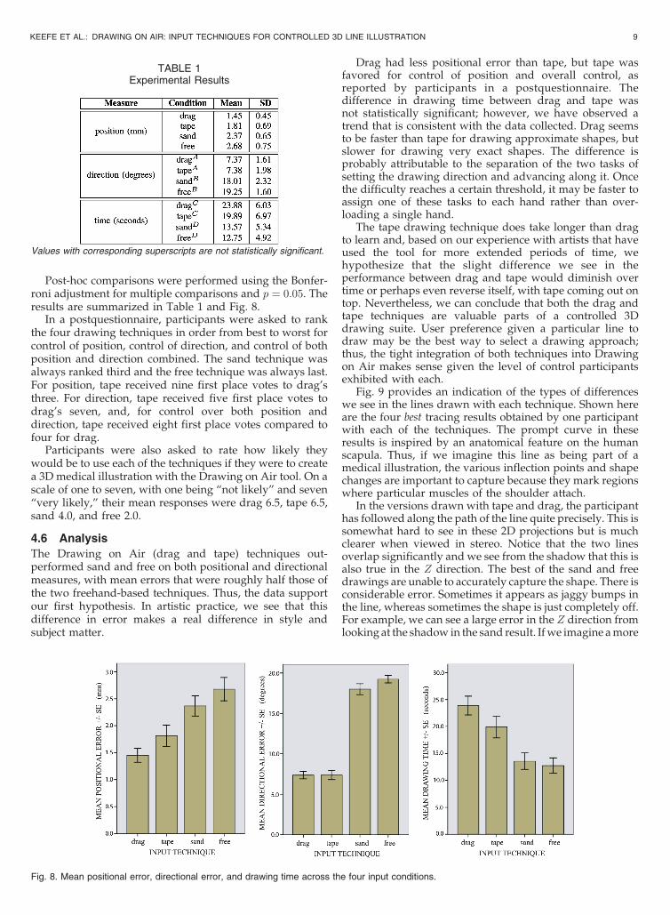
Post-hoc comparisons were performed using the Bonfer-roni adjustment for multiple comparisons and p ¼ 0:05. Theresults are summarized in Table 1 and Fig. 8.
In a postquestionnaire, participants were asked to rankthe four drawing techniques in order from best to worst forcontrol of position, control of direction, and control of bothposition and direction combined. The sand technique wasalways ranked third and the free technique was always last.For position, tape received nine first place votes to drag’sthree. For direction, tape received five first place votes todrag’s seven, and, for control over both position anddirection, tape received eight first place votes compared tofour for drag.
Participants were also asked to rate how likely theywould be to use each of the techniques if they were to createa 3D medical illustration with the Drawing on Air tool. On ascale of one to seven, with one being “not likely” and seven“very likely,” their mean responses were drag 6.5, tape 6.5,sand 4.0, and free 2.0.
4.6 Analysis
The Drawing on Air (drag and tape) techniques out-performed sand and free on both positional and directionalmeasures, with mean errors that were roughly half those ofthe two freehand-based techniques. Thus, the data supportour first hypothesis. In artistic practice, we see that thisdifference in error makes a real difference in style andsubject matter.
Drag had less positional error than tape, but tape wasfavored for control of position and overall control, asreported by participants in a postquestionnaire. Thedifference in drawing time between drag and tape wasnot statistically significant; however, we have observed atrend that is consistent with the data collected. Drag seemsto be faster than tape for drawing approximate shapes, butslower for drawing very exact shapes. The difference isprobably attributable to the separation of the two tasks ofsetting the drawing direction and advancing along it. Oncethe difficulty reaches a certain threshold, it may be faster toassign one of these tasks to each hand rather than over-loading a single hand.
The tape drawing technique does take longer than dragto learn and, based on our experience with artists that haveused the tool for more extended periods of time, wehypothesize that the slight difference we see in theperformance between drag and tape would diminish overtime or perhaps even reverse itself, with tape coming out ontop. Nevertheless, we can conclude that both the drag andtape techniques are valuable parts of a controlled 3Ddrawing suite. User preference given a particular line todraw may be the best way to select a drawing approach;thus, the tight integration of both techniques into Drawingon Air makes sense given the level of control participantsexhibited with each.
Fig. 9 provides an indication of the types of differenceswe see in the lines drawn with each technique. Shown hereare the four best tracing results obtained by one participantwith each of the techniques. The prompt curve in theseresults is inspired by an anatomical feature on the humanscapula. Thus, if we imagine this line as being part of amedical illustration, the various inflection points and shapechanges are important to capture because they mark regionswhere particular muscles of the shoulder attach.
In the versions drawn with tape and drag, the participanthas followed along the path of the line quite precisely. This issomewhat hard to see in these 2D projections but is muchclearer when viewed in stereo. Notice that the two linesoverlap significantly and we see from the shadow that this isalso true in the Z direction. The best of the sand and freedrawings are unable to accurately capture the shape. There isconsiderable error. Sometimes it appears as jaggy bumps inthe line, whereas sometimes the shape is just completely off.For example, we can see a large error in the Z direction fromlooking at the shadow in the sand result. If we imagine a more
KEEFE ET AL.: DRAWING ON AIR: INPUT TECHNIQUES FOR CONTROLLED 3D LINE ILLUSTRATION 9
TABLE 1Experimental Results
Values with corresponding superscripts are not statistically significant.
Fig. 8. Mean positional error, directional error, and drawing time across the four input conditions.

complete drawing formed by many lines like this, we can seethe problem that typically arises with freehand input. Thedrawing quickly becomes loose and imprecise. We get a senseof what the artist means, but not the clarified understandingwe desire in applications such as medical illustration.
More sophisticated input filtering techniques mightimprove some of the jaggy type of error that we see in thesand and free results. However, for anatomically inspiredlines, small kinks and shape changes in line are often used toindicate important features and they regularly occur at thesame scale as the muscular error we see with the sand and freetechniques. Thus, it is very difficult for automatic datafiltering to separate user error from artistic intention. The twoDrawing on Air techniques successfully avoid this issue byputting the user in continuous control of the drawingdirection, which we can think of as a user-guided filter.
The drawing times for both the drag and tape techniquestook significantly longer than for the freehand techniques.This raises the question, would performance with sand andfree be better if the participants spent more time whiledrawing when using these techniques? In practice, we findthat the answer is no. The sand and free techniques have a“sweet spot” in terms of drawing speed. If the drawing isdone too quickly, it is difficult to correctly capture the shapeof the curve. If the drawing is done too slowly, it is difficultto maintain a smooth movement of the hand, therebycontrolling directional error.
In contrast, the Drawing on Air techniques enabledeliberate drawing. There is no motor control penaltyassociated with drawing slowly and carefully and, at a highlevel, guidelines built into the techniques allow forcontinuously checking the position and orientation in spacewhile drawing. As a result, we find the familiar speedaccuracy trade-off that we desire in a drawing tool.Performance only increases when artists wish to investmore time in the drawing.
Of final note is the significant difference found betweenthe sand and free techniques in the mean positional error.The difference found supports our second hypothesis. Theaddition of haptic frictional and viscosity forces appears toaid control in this 3D task, although not to the level of themore sophisticated Drawing on Air techniques.
4.7 Appropriateness of the Task
Clearly, not all lines in an illustration are tracings. Thus, thequestion of whether a tracing task is the most appropriate fortesting control of the various drawing interfaces is raised. Infact, we piloted other tasks, such as replicating a line seen inthe distance. One of the main obstacles in nontracingapproaches is making sure that the participant has an
accurate 3D understanding of the shape they are about todraw. This is very difficult to achieve across variousparticipants with anywhere near the level of certainty wehave with tracing. Thus, with tracing, the participant hasfewer errors due to lack of understanding of 3D shape and ourerror measures are more reflective of how much control theparticipant has over the particular technique.
Tracing is also not so different from what illustratorstypically do, as we learned by working closely withillustrators and by doing our own serious illustrations.When artists work at an intricate level, drawing a line thathas a particular bump on it to convey exactly where atendon attaches to a bone, for example, they draw preciselyand deliberately. They are most definitely not sketchingwhen working at this level. The exact shape of the line isextremely important, just as it is in tracing. Lines are oftendrawn relative or even parallel to other lines and, in thesesituations, the act of drawing is almost exactly tracing.
The five prompt curves used in the tracing trials werechosen to be representative of curves found in anatomicalillustration, ranging from the simple bend of a tendon goingover a knuckle to a tracing of the spine of the scapula, anextremely important anatomical feature in figure drawingand illustrations of flying bats. All of the prompt curvescontain variation in all three dimensions.
4.8 Importance of Training and Depth Cues
Most participants were introduced to many new conceptsduring this study. The various drawing techniques were, ofcourse, new, but so was the very idea of virtual reality andinteracting with a 3D stereo display. In pilots, we found thatunderstanding depth relationships in VR was one of themost important and challenging hurdles for novices toovercome. In normal use of Drawing on Air, artists build upan entire drawing, checking depth relationships and evendrawing guidelines or scaffolding as they go. In this study,however, the prompt curve is seen completely in isolation,so there are no “relative size” visual cues and very few“occlusion” cues. Cutting and Vishton provide an overviewof these and other relevant cues in perceiving spatial layoutin near visual space [21].
To help participants learn to judge depth within this newenvironment, we paid special attention to the rendering of theexperimental scene, as shown in Fig. 7. Everything in thescene is textured, which helps with the perception of shape.Shadows and a ground plane, along with the bull’s-eye formsused extensively during the training session were also addedto provide additional cues for clarifying depth relationships.After adding these cues, a few of the participants stillcomplained that they were having difficulty getting used to
10 IEEE TRANSACTIONS ON VISUALIZATION AND COMPUTER GRAPHICS, VOL. 13, NO. 5, SEPTEMBER/OCTOBER 2007
Fig. 9. One participant’s best tracings of a line inspired by an anatomical feature. The prompt is shown as a dotted blue line. The user drew the solid
orange line.

working in 3D space, but, after the training trials, they becamecomfortable enough to accurately perform the task.
5 ILLUSTRATION RESULTS
Many artists have used Drawing on Air and providedvaluable feedback along the way. A few of these havereturned repeatedly to work on their own projects with thetool. We have guided these artists toward working onscientific illustrations of bat flight since it is a real-worldillustration problem that requires a 3D treatment. In thissection, we report on these results, as well as the moreartistically motivated results of the first author. Each of theseworks took between two to five hours to create. They aredesigned specifically to be viewed in stereo and admittedlylose a great deal of their impact and 3D character whenprinted on paper, but control of form and line quality can stillbe clearly seen in many of the examples.
5.1 Illustrations of Bat Flight
The illustrations in Figs. 1 and 10 were made by twodifferent artists as part of an ongoing collaboration with anevolutionary biologist studying bat flight. Traditionally,almost all anatomical illustrations, and even preservedspecimens of bats, have been presented with the wingmembrane and skeleton completely flattened, as we wouldexpect of a bird’s wing or a fixed wing aircraft. However,recent research has demonstrated that bat flight is severalorders of magnitude more complex than that of birds, inlarge part because the flexible wing membrane and bonesundergo tremendous 3D deformations during flight [22].
Because 3D understanding is so critical in this problem,3D presentations of bats posed in flight are extremelyimportant tools for the biologist researchers. Figs. 1 and 10show initial results working toward the goal of an animated3D anatomical illustration of a bat, including bones,muscles, and tendons with clear insertion and attachmentpoints. The illustration in Fig. 1 served as our initial proof ofconcept, whereas Fig. 10 is more representative of actualexperimental flight data. Several features of Drawing on Airare highlighted in aspects of both drawings. First, thesmooth curves of the wing bones are clearly indicated.These bones actually bend during flight. Thus, their shape is
important and would be impossible to convey accuratelywith a freehand approach to drawing. Also, in the bones,notice how the artist has adjusted the line thickness (seeinset detail in Fig. 1) to clearly indicate the joints.
The illustration in Fig. 10 is an illustration student’ssecond 3D bat drawing. It was drawn on top of 3D markersthat were imported into the system from data collected byflying bats in a wind tunnel. Twelve markers were placedon important joints in the wing and tracked by cameras. Weimported a frame of the resulting motion data into our tooland displayed the markers as blue spheres. Then, the artistdrew within the reference frame created by the markers tocreate an illustration that is highly representative of thescientific data yet stylized to clarify the role of the skeletalsystem in flight.
5.2 Artistic Anatomy
The lead author, who is also an artist, did a series of worksbased on artistic anatomy in collaboration with a professorof illustration who teaches anatomical drawing. Each workwas critiqued in VR from an artistic standpoint, and thedirection for the next work was decided upon based on thecritique and the goal of exploring the possibilities of themedium for representing complex natural forms. Three ofthe results are shown in Figs. 11, 12, and 13. When seentogether, we see that an interesting variation in style ispossible with Drawing on Air. Although the first batillustration and the bearded man are quite sculpted, theSwahili bride is created with minimal use of line. Onetheme that came out of critiques of this work was theeffectiveness of this minimal style. When seen in head-tracked stereo, we receive enough depth cues that a linedrawing like this exerts a tremendous 3D presence. Theartistic effect is as compelling, if not more so, as what wewould see with a more traditional full-surface representa-tion for the face.
The use of ribbons as the drawing primitive is importantfor making this style work because they suggest a smallportion of a larger surface. Fig. 13 is an experiment in usingthis minimal style for medical illustration. The end points ofthe bones are drawn out in detail, but the anatomically lessinteresting flat regions in the middle of the bones are merelysuggested. In many ways, this focus on detail in importantregions mimics the way an illustrator would work with 2D
KEEFE ET AL.: DRAWING ON AIR: INPUT TECHNIQUES FOR CONTROLLED 3D LINE ILLUSTRATION 11
Fig. 10. Two views from an illustration of a bat skeleton posed in a flight. The blue spheres are markers from motion captured data of a bat flying in a
wind tunnel.

physical media. Notice the control in the lines of thetendons running over the knuckles in this example, drawnwith the tape mode.
6 DISCUSSION
Drawing in 3D and drawing with two hands are both newways for most artists to work. In this section, we discusssome lessons learned about effective strategies for drawingwith correct proportion and picking the right lines to drawto make compelling 3D illustrations. We also discuss thederivation of the design for our elastic finger controller andsome nuances of working with tape drawing in 3D.
6.1 Strategies for Effective Use
Frequent reframe operations are an important part of theartistic process with Drawing on Air. Repositioning androtating the form increases 3D understanding of the shape. Itis also important for positioning the model appropriately fordrawing the next mark. This has special importance for thetape mode, where there is a clear preference for orienting theartwork so that lines can be drawn toward the nondominanthand. Reframing and scaling is also necessary to deal with thelimited range of the Phantom device, which was the mostfrequent criticism of the tool in responses to an open endedquestion in the postquestionnaire for the user study.
Artists also find it useful to create guidelines orscaffolding for refining 3D proportion before drawing afinal version. Our application supports drawing layers thatcan be turned on and off. Often, at least one layer is used forrough guidelines and working out 3D proportion.
In 3D line illustration, picking the right lines to draw isfar more difficult than in 2D because multiple viewpointsmust be considered. Silhouettes are often used in 2D tobound and define a form, but they break down in 3D whenthe form is intended to be viewed from multiple directions.Rather than drawing multiple 2D silhouettes, 3D illustra-tions are much more compelling when they are composedof lines that cross many planes of the form, often followingalong some important feature. In figure drawing, forexample, the serratus and oblique muscles of the side ofthe torso are a good choice for this type of characteristiccurve because they naturally spiral around the form fromalmost every viewpoint. When the edge of one of thesemuscles is traced out with a ribbon, the orientation of theribbon at each point in space helps clarify the 3D shape tothe viewer and lead the eye around the form.
One feature we plan to explore in the future is the view-dependent rendering of these 3D line illustrations. Theminimalist style of 3D drawing, as opposed to moresculptural approaches, lends itself to creating models withclear regions that we can see through. In some situations,such as the faces in Figs. 11 and 12, looking from theperspective of the rear of the model is interesting butdistracting because we see the features of the face insideout, ruining the impression of the back of the head. Forsome subjects, faces in particular, view-dependent displayof marks, including the ability to hide marks from certainviews, might facilitate clearer illustrations.
6.2 Controls for Line Weight
Pushing against the haptic line constraint in the tapedrawing mode to adjust line weight mimics the approachused in traditional media of pushing the drawing imple-ment into the paper to thicken and darken a line. Thedifficulty with moving this approach directly into 3D isknowing where to simulate the surface of the paper, giventhat, in the general case, it is impossible to predict where theartist will want to draw next. Tape drawing avoids thisprediction problem by separating the controls for setting thedrawing direction and advancing along it.
We did explore a one-handed technique that also separatesthese controls. The position of the brush is used to advance theline, while its orientation sets the drawing direction. Thisallows us to push against the linear drawing directionconstraint as we do with tape drawing to adjust line weight.The problem with this approach is that it requires extreme
12 IEEE TRANSACTIONS ON VISUALIZATION AND COMPUTER GRAPHICS, VOL. 13, NO. 5, SEPTEMBER/OCTOBER 2007
Fig. 11. Bearded man.
Fig. 12. A Swahili bride wearing a green veil.
Fig. 13. Muscles and tendons in the hand.

and unnatural bending of the wrist in order to move in andout of a plane and create complex marks.
The elastic hinge device for line weight adjustment is theresult of several design iterations, beginning with themouse-based control in Holosketch [8]. We also exploreda touch pad-based variant and an isometric pressure sensorused in either hand. In informal testing, the isometriccontroller was preferred to the isotonic mouse and touchpad and the final elastic design was preferred to theisometric one. Zhai notes greater ease of learning withelastic verses isometric controllers in 6-DOF manipulations[23]. We note a similar preference for the elastic overisometric controller for untrained users, but have yet toexplore how this may vary with additional experience.
Both methods for controlling line weight (the elastichinge and pushing against the tape drawing hapticconstraint) have their advantages. The finger-based methodis easier to hold at a constant value while drawing intricatecurves, whereas the haptic-based method seems easier tocontrol for simple curves, especially those that lie roughlywithin a plane.
6.3 Three-Dimensional Tape Drawing withoutHaptics
We tried a nonhaptic digital implementation of 3D tapedrawing, but, because there is no haptic constraint, thetrailing hand can stray from the curve. This makes our tapemode control for line weight impossible to realize. How-ever, even if we disable that feature, users are still frustratedby a lack of control. As in 2D digital implementations [4],we advance the drawing along the tangent line byprojecting the position of the trailing hand onto the tangent.Drifting of the trailing hand slightly off the curve is notsignificant enough in 2D to pose a problem, but, in 3D,keeping the trailing hand close to the curve is much moredifficult. When it drifts too far, its projection onto thetangent drawing guide can be in an unexpected place. Asthe 3D nature of the curves becomes more complex, thisdrifting increases until an unexpected projection causes thedrawing to appear to jump forward to the user.
6.4 Nondominant Hand Offset Mode
One of the limitations of tape drawing is the difficulty ofdrawing complete circles and other shapes that would requirethe hands to cross. We explored a mode in which the positionof the nondominant hand is offset horizontally by six inchestoward the dominant hand for all calculations. In this mode,the hands can easily cross virtually without crossingphysically, allowing the user to draw full circles with tapedrawing. Although this solves the circle limitation in theory,in practice, it requires much more of the user’s concentrationto work with such a large offset applied to the hand.
7 CONCLUSION
Drawing on Air enables artists to work with direct hand-based 3D input for creating controlled 3D models in a style ofillustration. It provides simultaneous control of position,orientation, and line weight of a 3D mark through two modesof interaction, each appropriate for important classes of3D curves. Mechanisms for transitioning from one-handed totwo-handed drawing preserve the fluidity of the interactionand the smooth quality of the curves. Haptic-aided curveredrawing, which preserves smoothness, enables artists toexplore subtle line variations with precision. Drawing on Air,
like other VR tools, leverages the benefits of working directlyin space but also provides the rich controllable interactionnecessary for refined 3D illustration.
Our illustration results demonstrate that artists caneffectively address challenging visual subjects in bothvisual art and science using Drawing on Air. We attributethis to the increased control afforded by Drawing on Air,coupled with the ability to adjust line weight. Our userstudy quantified a statistically significant improvement inaccuracy with Drawing on Air as compared to freehandtechniques. Drawing on Air is an important first steptoward making refined 3D illustration as accessible asdrawing on paper. We believe advances toward this goalwill enable both important artistic results and moreeffective scientific and medical illustrations.
ACKNOWLEDGMENTS
The authors would like to thank Misha Zaitzef and David
Eigen for their efforts contributing to this work. Thanks also
to Fritz Drury, Sharon Swartz, Cullen Jackson, Tomer
Moscovich, Timothy Miller, and John Hughes for helpful
discussions. This work was partially supported by the US
National Science Foundation (CNS-0427374).
REFERENCES
[1] D.F. Keefe, D.A. Feliz, T. Moscovich, D.H. Laidlaw, and J.J.LaViola Jr., “CavePainting: A Fully Immersive 3D ArtisticMedium and Interactive Experience,” Proc. Symp. Interactive 3DGraphics (I3D ’01), pp. 85-93, 2001.
[2] S. Schkolne, M. Pruett, and P. Schroder, “Surface Drawing:Creating Organic 3D Shapes with the Hand and Tangible Tools,”Proc. Conf. Human Factors in Computing Systems (CHI ’01), pp. 261-268, 2001.
[3] D.F. Keefe, D.B. Karelitz, E.L. Vote, and D.H. Laidlaw, “ArtisticCollaboration in Designing VR Visualizations,” IEEE ComputerGraphics and Applications, vol. 25, no. 2, pp. 18-23, Mar./Apr. 2005.
[4] R. Balakrishnan, G. Fitzmaurice, G. Kurtenbach, and W. Buxton,“Digital Tape Drawing,” Proc. User Interface and Software Technol-ogy (UIST ’99), pp. 161-169, 1999.
[5] T. Grossman, R. Balakrishnan, G. Kurtenbach, G. Fitzmaurice, A.Khan, and B. Buxton, “Creating Principal 3D Curves with DigitalTape Drawing,” Proc. Conf. Human Factors in Computing Systems(CHI ’02), pp. 121-128, 2002.
[6] T. Grossman, R. Balakrishnan, and K. Singh, “An Interface forCreating and Manipulating Curves Using a High Degree-of-Freedom Input Device,” Proc. Conf. Human Factors in ComputingSystems (CHI ’03), pp. 185-192, 2003.
[7] E. Sachs, A. Roberts, and D. Stoops, “3-Draw: A Tool forDesigning 3D Shapes,” IEEE Computer Graphics and Applications,vol. 11, no. 6, pp. 18-26, 1991.
[8] M.F. Deering, “Holosketch: A Virtual Reality Sketching/Anima-tion Tool,” ACM Trans. Computer-Human Interaction, vol. 2, no. 3,pp. 220-238, 1995.
[9] W. Makela, “Working 3D Meshes and Particles with Finger Tips,towards an Immersive Artists’ Interface,” Proc. IEEE VirtualReality Workshop, pp. 77-80, 2005.
[10] G. Wesche and H.-P. Seidel, “Freedrawer: A Free-Form SketchingSystem on the Responsive Workbench,” Proc. Virtual RealitySoftware and Technology (VRST ’01), pp. 167-174, 2001.
[11] M. Fiorentino, G. Monno, P.A. Renzulli, and A.E. Uva, “3D SketchStroke Segmentation and Fitting in Virtual Reality,” Proc. Int’l Conf.Computer Graphics and Vision (GRAPHICON ’03), pp. 188-191, 2003.
[12] S. Snibbe, S. Anderson, and B. Verplank, “Springs and Constraintsfor 3D Drawing,” Proc. Third Phantom Users Group, TechnicalReport AITR-1643, Mass. Inst. of Technology Artificial IntelligenceLaboratory, 1998.
[13] B. Baxter, V. Scheib, M.C. Lin, and D. Manocha, “DAB: InteractiveHaptic Painting with 3D Virtual Brushes,” Proc. ACM SIGGRAPH’01, pp. 461-468, 2001.
KEEFE ET AL.: DRAWING ON AIR: INPUT TECHNIQUES FOR CONTROLLED 3D LINE ILLUSTRATION 13

[14] T.A. Galyean and J.F. Hughes, “Sculpting: An InteractiveVolumetric Modeling Technique,” Proc. ACM SIGGRAPH ’91,Computer Graphics, vol. 25, no. 4, pp. 267-274, 1991.
[15] M. Foskey, M.A. Otaduy, and M.C. Lin, “Artnova: Touch-Enabled3D Model Design,” Proc. IEEE Virtual Reality (VR ’02), pp. 119-126,2002.
[16] A.D. Gregory, S.A. Ehmann, and M.C. Lin, “inTouch: InteractiveMultiresolution Modeling and 3D Painting with a Haptic Inter-face,” Proc. IEEE Virtual Reality (VR ’02), pp. 45-52, 2000.
[17] J. Hua and H. Qin, “Haptics-Based Dynamic Implicit SolidModeling,” IEEE Trans. Visualization and Computer Graphics,vol. 10, no. 5, pp. 574-586, Sept./Oct. 2004.
[18] SensAble Technologies, FreeForm Concept Product Brochure, 2005.[19] G. Ramos, M. Boulos, and R. Balakrishnan, “Pressure Widgets,”
Proc. Conf. Human Factors in Computing Systems (CHI ’04), pp. 487-494, 2004.
[20] R. Komerska and C. Ware, “Haptic State-Surface Interactions,”IEEE Computer Graphics and Applications, vol. 24, no. 6, pp. 52-59,Nov./Dec. 2004.
[21] J.E. Cutting and P.M. Vishton, Handbook of Perception and Cognition,Perceiving Layout and Knowing Distances: The Integration,Relative Potency, and Contextual Use of Different Informationabout Depth, Perception of Space and Motion, vol. 5, pp. 69-117,1995.
[22] S.M. Swartz, K.L. Bishop, and M.-F.I. Aguirre, Functional andEvolutionary Ecology of Bats, chapter on Dynamic Complexity ofWing Form in Bats: Implications for Flight Performance. OxfordUniv. Press, 2005.
[23] S. Zhai, “Human Performance in Six Degree of Freedom InputControl,” PhD dissertation, Univ. of Toronto, 1995.
Daniel F. Keefe received the BS degree incomputer engineering from Tufts University andthen the ScM degree in computer science in2001. He is a PhD candidate in computer scienceat Brown University. His research interestsinclude user interfaces, scientific visualization,and artistic computer tools. He has exhibited hisdigital artwork in juried shows and at academicconferences. He is a student member of the IEEEand the IEEE Computer Society.
Robert C. Zeleznik received the ScM degree incomputer science from Brown University, wherehe is currently director of user interface researchfor the Computer Graphics Group and theMicrosoft Center for Research on Pen-CentricComputing. His research interests include pen-centric computing, post-WIMP, gestural userinteraction, and design of 3D user interfaces.
David H. Laidlaw received the PhD degree incomputer science from the California Institute ofTechnology, where he also did postdoctoral workin the Division of Biology. He is an associateprofessor in the Computer Science Departmentat Brown University. His research centers onapplications of visualization, modeling, computergraphics, and computer science to other scien-tific disciplines. He is a senior member of theIEEE and the IEEE Computer Society.
. For more information on this or any other computing topic,please visit our Digital Library at www.computer.org/publications/dlib.
14 IEEE TRANSACTIONS ON VISUALIZATION AND COMPUTER GRAPHICS, VOL. 13, NO. 5, SEPTEMBER/OCTOBER 2007