ieee transactions on vehicular technology, …userweb.swjtu.edu.cn/userweb/xmfang/tvt16-1.pdf ·...
TRANSCRIPT
IEEE TRANSACTIONS ON VEHICULAR TECHNOLOGY, VOL. 65, NO. 12, DECEMBER 2016 9597
Hybrid Spatial Modulation Beamforming formmWave Railway Communication Systems
Yaping Cui, Xuming Fang, Senior Member, IEEE, and Li Yan
Abstract—Using higher frequency bands [e.g., millimeter wave(mmWave)] is the most effective and straightforward way to allevi-ate the bands scarcity at lower frequency bands (e.g., microwave)while simultaneously supporting the ever-growing data rate de-mands for future cellular networks. Cellular-networks-based high-speed railway (HSR) wireless communication systems also need tobe evolved to satisfy the requirements of train-ground data trans-mission by using higher frequency bands. An essential character-istic of HSR propagation channels is the strong line of sight, whichresults in high channel correlation. Therefore, the conventionalmultiple input multiple output (MIMO, e.g., VBLAST, STBC) isless effective under the HSR scenario. Moreover, the high complex-ity of the conventional MIMO makes it hard to achieve multipleantenna gain. Spatial modulation (SM) is a low complexity and highspectral efficiency multiple antenna technology that has emergedin recent years. The properties of SM imply that it may be a po-tential technique for improving the performance of HSR wirelesscommunication systems. In this paper, a hybrid SM beamform-ing scheme operating at mmWave frequency bands is proposedfor future 5G HSR wireless communication systems. The proposedscheme is designed in both analog and digital domains. In digi-tal domain, SM is used to activate antenna array (AA) indices toconvey information bits. RF beams are predefined and the opti-mal beams are selected to transmit modulation symbols in analogdomain. Theoretical analysis and numerical results indicate thatthe proposed scheme achieves a good compromise between perfor-mance and complexity. Multiple antenna gain, which is difficult toachieve by the conventional MIMO, can be almost achieved by theproposed scheme due to analog beamforming. Numerical resultsfurther show that the performance of the proposed scheme is notsensitive to the number of predefined RF beams, but it is to someextent sensitive to both AAs at base station and antenna elementsin an AA on the train.
Index Terms—5th-generation (5G) networks, hybrid beamform-ing, massive multiple input multiple output (MIMO), millimeterwave (mmWave), spatial modulation (SM).
I. INTRODUCTION
LOWER frequency bands (e.g., microwave) for cellularcommunication systems have been almost used up in re-
cent years, which means that there are not enough frequencybands in the current range for future cellular networks (e.g.,
Manuscript received February 23, 2016; revised June 15, 2016 and September21, 2016; accepted September 24, 2016. Date of publication September 27, 2016;date of current version December 14, 2016. This work was supported in part bythe 973 Program under Grant 2012CB316100, in part by the National NaturalScience Foundation of China under Grant 61471303, and in part by the Programfor Development of Science and Technology of China Railway Corporationunder Grant 2015X007-B. The review of this paper was coordinated by Editorsof CVS TVT. (Corresponding author: X. Fang.)
The authors are with the Key Laboratory of Information Coding andTransmission, School of Information Science and Technology, SouthwestJiaotong University, Chengdu 610031, China (e-mail; [email protected];[email protected]; [email protected]).
Color versions of one or more of the figures in this paper are available onlineat http://ieeexplore.ieee.org.
Digital Object Identifier 10.1109/TVT.2016.2614005
5G networks). To support high data rate demands of future cel-lular networks, one of the most effective and straightforwardways is to exploit higher frequency bands [e.g., millimeter wave(mmWave)] [1]. Similarly, for cellular-networks-based high-speed railway (HSR) wireless communication systems, they alsoneed to be evolved to satisfy the requirements of train-grounddata transmission, such as safety-critical railway signaling, andpassengers Internet access services [2]. Thus, the higher fre-quency bands are also needed for use in future HSR wirelesscommunication systems.
Theoretical analysis and measured data have indicated thathigher frequency bands are potential sources for future cellularcommunication systems [1]. However, higher frequency signalswill experience orders of magnitude and more path loss thanthe microwave frequency signals used in current cellular com-munication systems. Therefore, large scale antenna arrays withbeamforming must be used to combat the severe path loss ofhigher frequency bands.
Large scale antenna arrays [AA, also known as massive mul-tiple input multiple output (MIMO)], which use tens or evenhundreds of antenna elements simultaneously serving many ter-minals, has emerged in the last few years [3]. As the numberof transmit antennas grows without bound, the effects of un-correlated noise and fast fading disappear, and the high degreeof freedom (DoF), spectral efficiency, and antenna gain are allachieved [3], [4]. Besides, when beamforming is employed, thesignal energy can be focused on a small region to improve thethroughput. Nevertheless, massive MIMO will result in pilotcontamination and lower energy efficiency [4]. Moreover, theeffect of hardware cost (e.g., one RF chain associated with eachantenna) is more severe when a massive number of transmitantennas are equipped [5]. However, the performance improve-ment of multiple antennas is attributed to the assumption that thefading channels are uncorrelated, which is not necessarily truefor HSR wireless communication systems. As we know, at leastin China, the typical terrain for HSR is viaduct [6]. The mea-sured data and theoretical analysis have shown that the viaductterrain may lead to a relatively clear line of sight (LOS) andfew scatters, thereby resulting in strong channel correlation [6].Therefore, multiple antenna gain may be less achieved by theconventional MIMO (e.g., VBLAST, STBC) for HSR wirelesscommunication systems in such scenarios. Besides, the highcomplexity of the conventional MIMO means that multiple an-tenna gain is difficult to be achieved.
Therefore, there is strong motivation and interest to inves-tigate an SM-based solution to take advantage of multipleantenna gain with massive MIMO while simultaneously reducethe number of RF chains for HSR wireless communicationsystems.
0018-9545 © 2016 IEEE. Personal use is permitted, but republication/redistribution requires IEEE permission.See http://www.ieee.org/publications standards/publications/rights/index.html for more information.

9598 IEEE TRANSACTIONS ON VEHICULAR TECHNOLOGY, VOL. 65, NO. 12, DECEMBER 2016
The first type of solution is to use spatial modulation (SM),which exploits the spatial dimension (i.e., transmit antenna in-dices) as an additional dimension to convey information bitsin addition to information bits conveyed through modulationsymbols (e.g., PSK, QAM) during transmission [7]. In SM, thespectral efficiency is improved, the intercarrier interference iscompletely eliminated, and only one single RF chain is required.Thus, the implementation cost and complexity can be reduced,which implies that SM has the potential advantages comparedwith the conventional MIMO solution. In addition, the spectralefficiency of SM can be further improved by a massive numberof transmit antennas [8]. Measured data in [9] have also shownthat the performance of SM under LOS is better than that underNLOS when the transmit power is constrained as a constant. Ourprevious work further shows that the better performance can beachieved with an appropriate scheme in SM systems under theHSR scenario [10]. These properties imply the feasibility ofSM for HSR wireless communication systems. Investigationsof SM can be also found in many other literatures. In [11]–[13],the average bit error probability (ABEP) of SM was analyzedover spatial correlated Rician fading channels. The upper boundon the ABEP was also exactly obtained. In [14]–[16], severallow complexity detection algorithms were proposed to reducethe exponential complexity of the maximum likelihood (ML)detector for massive SM MIMO systems. In [17]–[19], the per-formance of SM was analyzed using the measured data andexperimental testbed. In [10], [20], and[21], the performanceof SM under vehicular channels, including vehicle-to-vehicle(V2V) and vehicle-to-infrastructure (V2X), and HSR propaga-tion channels were analyzed. A general survey of the SM designframework was provided in [22]. However, the multiple antennagain has not been fully achieved due to strong LOS under anHSR scenario.
The second type of solution is to use the hybrid beamformingarchitecture, which consists of analog and digital domains [23],[24]. In this architecture, the sharp RF beams formed by analogbeamforming are used to compensate for the severe path lossat higher frequency bands, and digital baseband precoding isperformed to provide the necessary flexibility. In [23], a hybridbeamforming architecture was proposed that jointly combinesRF beamforming and baseband precoding to compromise be-tween performance and complexity. In [24], an iterative hybridprecoding algorithm for single user was proposed that exploitsboth the sparse and reciprocal natures of higher frequency bands,and a variant of matching pursuit was also used to provide sim-ple solutions to the hybrid beamforming problem to approachthe rates achieved by digital beamforming. In [25], a multibeamtransmission diversity scheme for the single user was proposed,which is based on a hybrid beamforming architecture that com-bines an analog beamforming with AAs and a digital basebandprecoding with multiple RF chains. Kim et al. [26] extended thisarchitecture to the architecture with the shared AA. In this novelarchitecture, the AA is shared by multiple analog beams. In [27],the spatial nature of higher frequency bands was exploited toformulate the precoding/combining problem as a sparse recon-struction problem. And the principle of basis pursuit was usedto develop low hardware complexity spatially sparse precodingand minimum mean square error combining. Numerical results
of the proposed algorithms accurately approximated optimalunconstrained precoders and combiners. In [28], a low com-plexity hybrid analog/digital precoding algorithm was proposedfor multiuser massive MIMO systems leveraging the sparse na-ture of higher frequency bands to approach the performanceof unconstrained digital beamforming. Simulation results alsoshowed that the hybrid precoding gain was not very sensitive toRF angles quantization, which is important to have a good quan-tization for the digital precoding layer to maintain a reasonableprecoding gain over analog-only solutions. The performance ofbaseband precoding in the hybrid beamforming architecture de-pends on the accuracy of channel estimation. Various channelestimation schemes have been proposed to obtain accurate chan-nel estimation under high mobility scenario [29]–[31]. There-fore, we assume that the channel estimation error can be almostwell compensated by other elaborate solutions. This assumptionis valid because the movement of the train is regular, and thelocation as well as the velocity information can be predictablein HSR wireless communication systems with linear coveragetopology [32]–[34]. In HSR wireless communication systems,the location and velocity of the train are strictly controlled bycontrol systems according to the predesigned velocity–distanceoperation diagram. Not only the safety-critical railway signal-ing (e.g., train control signaling) is transmitted but also thepassengers Internet access is provided [2], [35]. Therefore, thecommunication system part and the control system part are nor-mally jointly designed for professional HSR. In these jointlydesigned systems, additional hardware will never be required toobtain the location and velocity information since the regularlocation and velocity information has already been generated inthe control systems. The train periodically reports the locationand velocity information in signaling systems, which could beused to calculate the train movement authority [35], [36]. Fur-thermore, the location information could be exploited to furtherimprove the accuracy of channel estimation in communicationsystems [31], [37]. Although in practical systems, the regularmovement of the train may be influenced by sudden emergentevents, it has negligible effect on the performance since thestatistical regularity of the train movement is not changed.
For HSR communication systems, there are many importantissues that need to be investigated, such as accurate channelmodeling, frequent handover, and reliable transmission. In [38]–[41], the geometry-based stochastic model and Markov chainwere used to describe and develop the nonstationary proper-ties of HSR wireless channels. In [32], [42], and [43], loca-tion information-assisted opportunistic beamforming, adaptiveantenna-activation based beamforming, and massive MIMO-based adaptive multistream beamforming were proposed to im-prove the system performance. In [44] and[45], the handoverproblem was formulated as a partially observable Markov de-cision process. Handover decisions were made and physicallayer MIMO parameters were adapted to minimize the com-munication latency to optimize the train control performance incommunication-based train control systems.
Based on the aforementioned background, a hybrid SM beam-forming scheme is proposed for HSR wireless communicationsystems at mmWave frequency bands. It is designed in bothanalog and digital domains. In digital domain, SM is used to

CUI et al.: HYBRID SPATIAL MODULATION BEAMFORMING FOR MMWAVE RAILWAY COMMUNICATION SYSTEMS 9599
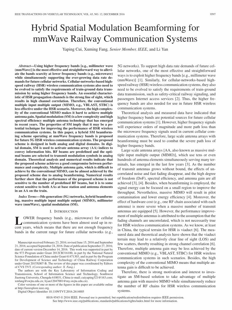
Fig. 1. System model.
choose active transmit AA indices. In analog domain, RF beamsare predefined and the optimal beams are selected to transmitmodulation symbols. As mentioned previously, much essentialwork on SM has indeed been conducted by the authors in [7],[13], [17], [18], [20], and [22]. They have provided some im-portant conclusions on the performance of SM over differentfading channels. However, our contribution is to extend thework and propose an SM-based solution by exploiting the prop-erties of SM under HSR scenario. Then, the proposed scheme iscompared with the conventional SM and full digital dual beam-forming. In dual beamforming, two beam streams are used totransmit data streams to AAs mounted at both the front and rearof the train, respectively. The AAs are connected by a systembus to a central unit where received signals are processed. Theo-retical analysis and numerical results indicate that the proposedscheme can achieve a good compromise between performanceand complexity. Multiple antenna gain, which is difficult toachieve in the conventional MIMO, can be almost achieved bythe proposed scheme. Numerical results further show that theperformance of the proposed scheme is not sensitive to the num-ber of predefined RF beams, but it is to some extent sensitive toboth AAs at the base station (BS) and antenna elements in theAA on the train.
The rest of this paper is organized as follows. In Section II,the system model is presented. In Section III, the proposedhybrid SM beamforming scheme is described in details, whichis then compared with the conventional SM and full digitaldual beamforming. The performance of the proposed schemeis analyzed in Section IV. Numerical results and discussionsare given in Section V. Section VI concludes this paper bysummarizing the results and suggesting some future work.
Notation: Boldface capital and lowercase symbols representmatrices and column vectors, respectively. [·]∗, [·]T , and [·]Hdenote conjugate, transpose, and Hermitian transpose, respec-tively. ‖ · ‖F and | · | denote the Frobenius norm and absolutevalue, respectively. (·)! denotes factorial. log2(·) denotes binarylogarithm. E[·] denotes expectation. I(·) is an identity matrixand Cn represents the set of complex n-vector.
II. SYSTEM MODEL
Consider the system model of hybrid SM beamforming forHSR wireless communication systems depicted in Fig. 1. Thetrackside BS is equipped with uniform planar arrays (UPA),where NAA UPA AAs are spaced along a straight line on thex-axes. Each AA comprises NT antenna elements, which are
evenly spaced in the form of a UPA. Thus, the total number ofantenna elements at the BS can be calculated as NBS = NAANT .Similarly, NU uniform linear arrays (ULAs) AA are evenlydeployed on the roof of the train. And each AA comprisesNR antenna elements in the form of an ULA. Thus, the totalnumber of antenna elements on the train can be calculated asNMS = NU NR .
For the sake of simplicity, each AA with equal antenna el-ements and interelement spacing at the BS and the train, re-spectively, are assumed. And we consider the total number ofantenna elements at the BS is not less than that on the train (i.e.,NBS ≥ NMS). Since ULA AAs on the train are far from eachother, we assume that each ULA AA is a virtually independentuser. Furthermore, we assume that each virtual user is servicedby only one RF beam transmitted by one single data stream(i.e., NU = NB = NS ), where NB and NS are the number ofselected beams and transmitted data streams, respectively. Forthe sake of mathematical analysis, the distance between the firstUPA AA at the BS and the first ULA AA on the train is denotedas d, as seen in Fig. 1. Although only downlink is considered inthis paper, the proposed scheme can be extended to the uplinkbecause multiple AAs can be deployed on the roof of the traindue to its size.
The information bits are divided into two parts in the pro-posed scheme, which is described in Section III-A in detail.The first part is used to match the transmitted AA index andthe second part is used to match the modulation symbol. Then,the modulation symbol is transmitted at the active AA by theselected analog RF beam. In the proposed scheme, the AAs areexploited as an additional dimension that is different from theconventional SM. Conventionally, the transmit antenna indicesare exploited as the additional dimension invoked for transmit-ting information bits.
Thus, the sampled transmitted signal x ∈ CNT ×1 can beexpressed as
x = F RFs (1)
where F RF = [f 1RF,f
2RF, . . . ,f
NU
RF ] ∈ CNT ×NU is the analogtransmit beamforming weight vectors. s = [s1
j,q , s2j,q , . . . ,
sij,q , . . . , s
NUj,q ]T ∈ CNU ×1 is the super symbols, including
modulation symbol of each data stream, where sij,q denotes
modulation symbol sq of ith data stream transmitted by jthAA at the BS, i = 1, 2, . . . , NU , and j ∈ {1, 2, . . . , NAA}.The modulation symbol depends on the used modulation order(e.g., M -QAM).
Then, the received signal ri for ith data stream with ith RFbeam processed by RF receive beamforming weight vector canbe expressed as
ri =√
ρi
NU∑
n=1
(wnRF)
H H i,jfnRFsn + (wi
RF)H ni (2)
where ρi represents the average received power, which de-pends on path loss [46]. wi
RF is the analog receive beamform-ing weight vector. H i,j ∈ CNR ×NT is the channel matrix be-tween the jth active AA at the BS and the ith virtual user (i.e.,ULA AA) on the train. ni ∈ CNR ×1 are independent identically
9600 IEEE TRANSACTIONS ON VEHICULAR TECHNOLOGY, VOL. 65, NO. 12, DECEMBER 2016
distributed (i.i.d) complex Gaussian variables with zeros meanand variance σ2.
A geometric channel model with Li scatterers is adopted [28].Under this model, the channel matrix H i,j can be expressed as
H i,j =√
NT NR
Li
Li∑
l=1
αi,lar (φri,l , θ
ri,l)at(φt
i,l , θti,l)
H (3)
where αi,l is the complex gain with∑Li
l=1 αi,l = 1. φri,l(θ
ri,l) and
φti,l(θ
ti,l) are azimuth (elevation) arrival and departure angles,
respectively. The vectors ar (φri,l , θ
ri,l) and at(φt
i,l , θti,l) are the
received and transmitted array response vectors (i.e., steeringvectors) at the corresponding arrival and departure angles.
In this paper, two types of array geometries are used: UPA andULA. For an N -element ULA on the x-axis, the array responsevector is [27]
aULA(φ) =1√N
[1, eIkΔ sin (φ) , . . . , eI (N −1)kΔ sin (φ)]T
(4)
where I =√−1, k = 2π/λ, λ is carrier wavelength, and Δ is
interelement spacing.For a UPA in the xz-plan with W and H elements on the z-
and x-axes, respectively, the array response vector is [27]
aUPA(φ, θ) =1√N
[1, eIkΔ(m sin (φ) sin (θ)+n cos (θ)) , . . . ,
eIkΔ((W −1) sin (φ) sin (θ)+(H−1) cos (θ))]T(5)
where 0 ≤ m ≤ W and 0 ≤ n ≤ H are the z and x indices ofan antenna element, respectively, and N = WH .
Analog beamforming is supposed to be used at both the BSand the train. A simple direction-of-arrival-based estimation isused [23]. Then, analog beamforming weight vectors at the BSand the train can be, respectively, expressed as
f iRF = at(φi, θi) (6a)
wiRF = ar (φi). (6b)
III. HYBRID SM BEAMFORMING SCHEME
In this section, the proposed hybrid SM beamforming schemeis described, then the proposed scheme is compared with theconventional SM and full digital dual beamforming.
A. Implementation of the Proposed Scheme
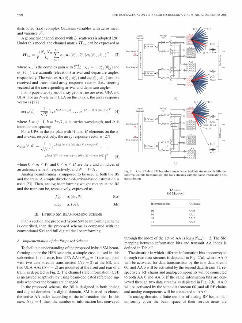
To facilitate understanding of the proposed hybrid SM beam-forming under the HSR scenario, a simple case is used in thissubsection. In this case, four UPA AAs (NAA = 4) are equippedwith two data streams transmission (NS = 2) at the BS, andtwo ULA AAs (NU = 2) are mounted at the front and rear of atrain, as depicted in Fig. 2. The channel state information (CSI)is measured adaptively by using beam-dedicated reference sig-nals whenever the beams are changed.
In the proposed scheme, the BS is designed in both analogand digital domains. In digital domain, SM is used to choosethe active AA index according to the information bits. In thiscase, NAA = 4; thus, the number of information bits conveyed
Fig. 2. Cse of hybrid SM beamforming scheme. (a) Data streams with differentinformation bits transmission. (b) Data streams with the same information bitstransmission.
TABLE ISM MAPPING
Information Bits AA Index
00 AA 001 AA 110 AA 211 AA 3
through the index of the active AA is log2(NAA) = 2. The SMmapping between information bits and transmit AA index isdefined in Table I.
The situation in which different information bits are conveyedthrough two data streams is depicted in Fig. 2(a), where AA 0will be activated for data transmission by the first data stream00, and AA 3 will be activated by the second data stream 11, re-spectively. RF chains and analog components will be connectedto both AA 0 and AA 3. If the same information bits are con-veyed through two data streams as depicted in Fig. 2(b), AA 0will be activated by the same data stream 00, and all RF chainsand analog components will be connected to AA 0.
In analog domain, a finite number of analog RF beams thatuniformly cover the beam space of their service areas are

CUI et al.: HYBRID SPATIAL MODULATION BEAMFORMING FOR MMWAVE RAILWAY COMMUNICATION SYSTEMS 9601
predefined as a candidate beams’ set (denoted as NBSST ),
and beam indices (BIs) are used to distinguish the differ-ent RF beams [23], [25]. Then, the optimal beams are se-lected based on the selection metric such as capacity maxi-mization. The number of selected beams is identical to thatof data streams, i.e., every data stream is transmitted byone analog RF beam. In this case, if different AAs are acti-vated, one RF beam is selected in AA 0 to transmit the first datastream, and the other RF beam is selected in AA 3 to transmitthe second data stream, respectively, depicted in Fig. 2(a). Ifthe same AA is activated, such as AA 0 in this case, two RFbeams are selected in AA 0 to transmit the two data streams, asdepicted in Fig. 2(b).
As for the train, two ULA AAs are supposed to be mountedat the front and rear of the train connected by a high-speed sys-tem bus to a central unit where received signals are processed.Each AA comprises two antenna elements in the form of anULA. Furthermore, each ULA AA is assumed as a virtuallyindependent user, which is serviced by one RF beam, and eachRF beam transmits one single data stream. Then, the receivedsignals are combined to achieve multiplexing gain. In Fig. 2(a),the ULA 0 receives the first data stream transmitted by ana-log RF beam from AA 0, and the ULA 1 receives the seconddata stream transmitted by analog RF beam from AA 3. Then,the two received data streams are converged and processed. Inthe conventional MIMO, all received antennas are utilized si-multaneously to receive all the signals transmitted by the BS.Different from the conventional MIMO, one data stream is re-ceived through a certain ULA AA on the train in our proposedscheme, other data streams are considered as interference.
Although the proposed scheme in this subsection is describedusing a simple case, which transmits only two data streams, it ac-tually can be easily extended to transmit multiple data streams.However, the interbeam interference and hardware cost (e.g.,one RF chain associated with each data stream) will becomeseverer as the number of data streams increases. Thus, the trade-off between performance and hardware cost must be consideredfor a generalized solution.
B. Comparisons Among Different SM Schemes
To demonstrate the features of different SM schemes, wecompare the proposed hybrid SM beamforming with the con-ventional SM and full digital dual beamforming. In dual beam-forming, two beams are similarly used to transmit data streamsto AAs mounted at both the front and rear of the train, respec-tively.
Multiplexing gain can be obtained by all these three schemesbecause multiple data streams transmission can be supported bymultiple RF chains in these schemes. In the proposed schemeand full digital dual beamforming, the severe path loss causedby higher frequency bands can be overcome with beamforminggain. Meanwhile, the conventional SM will suffer a severe dropin the performance because large path loss cannot be compen-sated. In digital dual beamforming, the better performance tothe proposed scheme can be achieved because the directions ofbeams can be adjusted and tracked simultaneously with respect
TABLE IICOMPARISONS AMONG DIFFERENT SCHEMES
Proposed Conventional Full DigitalScheme SM Dual Beamforming
Multiplexing gain Yes Yes YesBeamforming gain Yes No YesBeam tracking No - YesCost and complexity Moderate Low HighFlexibility Low - High
to the location of the train. The high computational complexityis of course inevitable due to beam tracking in digital dual beam-forming. In the proposed scheme, a candidate RF beams’ set ispredefined in the service areas. Instead of beam tracking, beamselection is required in the proposed scheme, which reduces thecomplexity of calculating the solution.
The hardware cost and complexity mainly depend on RFchains. In full digital dual beamforming, there is one RF chainassociated with each transmit antenna, which results in highcost and complexity. In the conventional SM and the proposedscheme, only one RF chain is associated with each data stream,which reduces the cost and complexity. In addition, the ana-log components, such as phase shifter, mixer, and power am-plifier, are needed in the proposed scheme. Thus, the cost ofthe proposed scheme is a little bit higher than the conven-tional SM. The proposed scheme comprises analog domain,which implies that the flexibility is less than full digital dualbeamforming.
The comparisons are summarized in Table II. In the pro-posed scheme, baseband precoding is replaced by SM in digitaldomain, which highly reduces the cost and complexity. In theanalog domain, RF beams are used to compensate the large pathloss, which results in less flexibility than that of digital beam-forming. Thus, the proposed scheme is a compromise amonghardware cost, complexity, and flexibility with multiplexinggain and beamforming gain.
IV. PERFORMANCE ANALYSIS
The performance of the proposed hybrid SM beamforming isanalyzed in this section using sum rate and ABEP.
A. Sum Rate
The mutual information for ith virtual user (i.e., ULA AA)can be expressed as [47]
I(sij,q ; ri) = He(ri) − He(ri |si
j,q ) (7)
where He(z) denotes the differential entropy of a continuousrandom variable z, and it can be defined as
He(z) = −∫ ∞
−∞f(z) log2 f(z)dz (8)
where f(z) is the probability density function of randomvariable z.
9602 IEEE TRANSACTIONS ON VEHICULAR TECHNOLOGY, VOL. 65, NO. 12, DECEMBER 2016
Then, the upper bound of achievable rate for ith virtual usercan be expressed as [28], [48]
Ri =1
NAA
NAA∑
j=1
log2
(1 +
ρi‖(wiRF)
H H i,jfiRF‖2
∑n =i
‖(wnRF)H H i,jfn
RF‖2 + σ2
)
+ log2 NAA
(9)
where H i,j ∈ CNR ×NT is the channel matrix between the jthactive UPA AA at the BS and the ith virtual user at the train.
Thus, the sum rate of the system can be expressed as
Rsum =NU∑
i=1
Ri. (10)
B. ABEP
The optimum ML detector proposed in [49] is supposed to beemployed to estimate the active transmit UPA AA index ji andthe selected modulation symbol index qi as
[ji , qi ] = arg maxji ,qi
pR(ri |sijq , (w
iRF)
H H i,jfiRF)
= arg minji ,qi
(‖ri − (wiRF)
H H i,jfiRFs
ij,q‖2
F ).(11)
For the sake of mathematical analysis, hi,jef f = (wi
RF)H H i,j
f iRF is defined. Thus, (10) can be rewritten as
[ji , qi ] = arg maxji ,qi
pR(ri |sijq , h
i,jef f )
= arg minji ,qi
(‖ri − hi,jef f si
j,q‖2F ). (12)
The ABEP of the hybrid SM beamforming for ith virtualuser with optimum ML detector given in (11) can be computedas [50]
P ib ≤ 1
NAAM − 1
NAA∑
j=1
NAA∑
j=1
M∑
q=1
M∑
q=1
N(j, j, q, q)log2(NAAM)
P is (j, j, q, q)
(13)
where N(j, j, q, q) is the Hamming distance between the re-
spective channel and symbol pairs, (hi,jeff , s
ij,q ) and (hi,j
eff , sij,q ).
P is (j, j, q, q) is the average pairwise symbol error probability
(APEP) for ith virtual user.The average ratio N(j, j, q, q)/log2(NAAM) is given by [51]
N(j, j, q, q)log2(NAAM)
≈ 12. (14)
Substituting (14) into (13), ABEP for ith virtual user can berewritten as
P ib ≤ 1
2(NAAM − 1)
NAA∑
j=1
NAA∑
j=1
M∑
q=1
M∑
q=1
P is (j, j, q, q). (15)
APEP for ith virtual user can be expressed as [12]
P is (j, j, q, q) = EH
[Q(
√‖zi‖2)
](16)
TABLE IIIPARAMETER SETTINGS
Parameters Values
Carrier frequency 28 GHzChannel bandwidth 500 MHzSubcarrier space 270 kHzTotal BS transmit power 46 dBmInterelement spacing 0.5λ
Number of ULA at train 2Cell radius 1.2 kmDistance from BS to track 30 mTrain length 200 mNoise figure 7 dBThermal noise −174 dBm/Hz
where Q(x) = 1√2π
∫ ∞x exp(− t2
2 )dt and zi =√
ρi
2 (hi,jef f si
j,q −hi,j
ef f xij,q ).
Thus, ABEP of the system can be expressed as
Pb = E[P i
b
]. (17)
V. NUMERICAL RESULTS AND DISCUSSIONS
In this section, the theoretical analysis presented in the previ-ous section is validated by numerical results. Then, some chal-lenges of the proposed scheme are discussed.
A. Numerical Results
Numerical results on the performance of the proposed schemeare given and compared with the conventional SM and full dig-ital dual beamforming. In digital dual beamforming, the simpleMRT precoding is used. And in the proposed scheme, there arefour antenna elements on the z- and x-axis, respectively, for eachUPA AA at the BS. Furthermore, the interelement spacing ofUPA AA at the BS equals to that of ULA AA at the train. In [52],the feasibility of higher frequency bands have been investigatedunder HSR scenario. Thus, we use mmWave frequency bandsin our numerical studies. The value of carrier frequency is set to28 GHz. Besides, LTE standard is taken as a baseline to evaluatethe performance of the proposed scheme. The detailed values ofparameters are listed in Table III [10], [23].
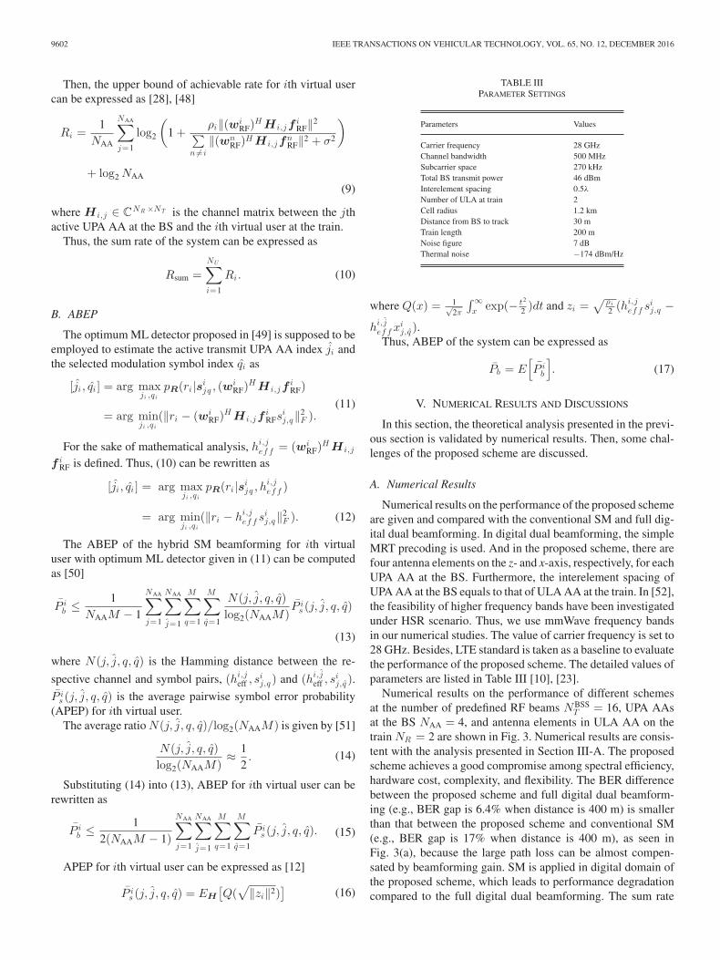
Numerical results on the performance of different schemesat the number of predefined RF beams NBSS
T = 16, UPA AAsat the BS NAA = 4, and antenna elements in ULA AA on thetrain NR = 2 are shown in Fig. 3. Numerical results are consis-tent with the analysis presented in Section III-A. The proposedscheme achieves a good compromise among spectral efficiency,hardware cost, complexity, and flexibility. The BER differencebetween the proposed scheme and full digital dual beamform-ing (e.g., BER gap is 6.4% when distance is 400 m) is smallerthan that between the proposed scheme and conventional SM(e.g., BER gap is 17% when distance is 400 m), as seen inFig. 3(a), because the large path loss can be almost compen-sated by beamforming gain. SM is applied in digital domain ofthe proposed scheme, which leads to performance degradationcompared to the full digital dual beamforming. The sum rate
CUI et al.: HYBRID SPATIAL MODULATION BEAMFORMING FOR MMWAVE RAILWAY COMMUNICATION SYSTEMS 9603
Fig. 3. Numerical results on the performance of different schemes. (a) Biterror rate comparison. (b) sum rate comparison.
gap between the proposed scheme and dual beamforming (e.g.,5 bit/s/Hz when distance is 400 m) is larger than the gap (e.g., 2bit/s/Hz when distance is 400 m) between the proposed schemeand conventional SM, as seen in Fig. 3(b).
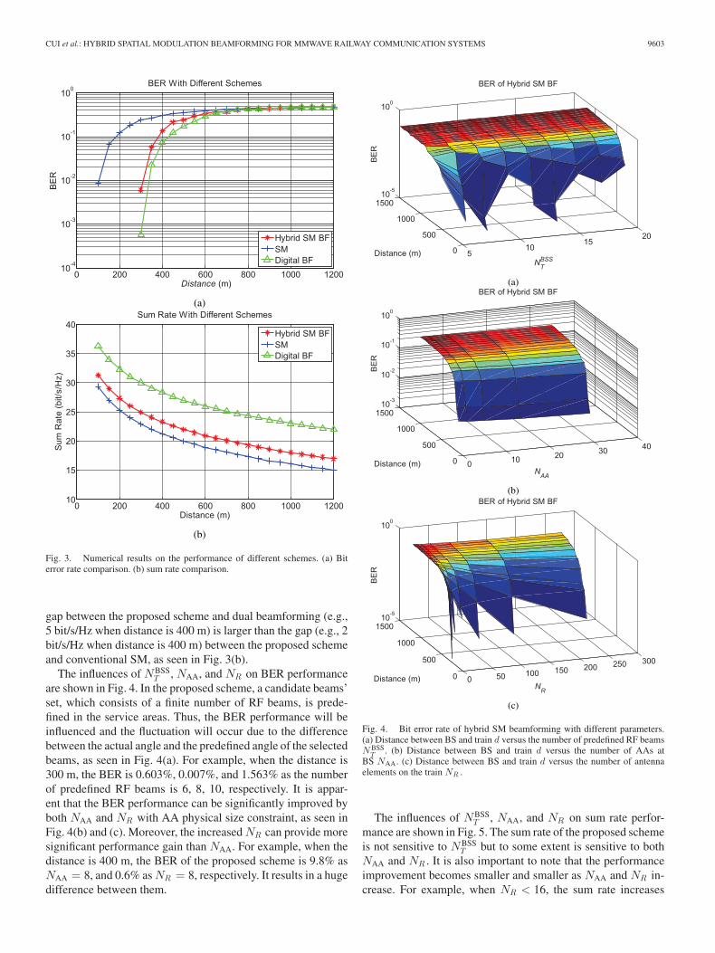
The influences of NBSST , NAA, and NR on BER performance
are shown in Fig. 4. In the proposed scheme, a candidate beams’set, which consists of a finite number of RF beams, is prede-fined in the service areas. Thus, the BER performance will beinfluenced and the fluctuation will occur due to the differencebetween the actual angle and the predefined angle of the selectedbeams, as seen in Fig. 4(a). For example, when the distance is300 m, the BER is 0.603%, 0.007%, and 1.563% as the numberof predefined RF beams is 6, 8, 10, respectively. It is appar-ent that the BER performance can be significantly improved byboth NAA and NR with AA physical size constraint, as seen inFig. 4(b) and (c). Moreover, the increased NR can provide moresignificant performance gain than NAA. For example, when thedistance is 400 m, the BER of the proposed scheme is 9.8% asNAA = 8, and 0.6% as NR = 8, respectively. It results in a hugedifference between them.
Fig. 4. Bit error rate of hybrid SM beamforming with different parameters.(a) Distance between BS and train d versus the number of predefined RF beamsN BSS
T . (b) Distance between BS and train d versus the number of AAs atBS NAA. (c) Distance between BS and train d versus the number of antennaelements on the train NR .
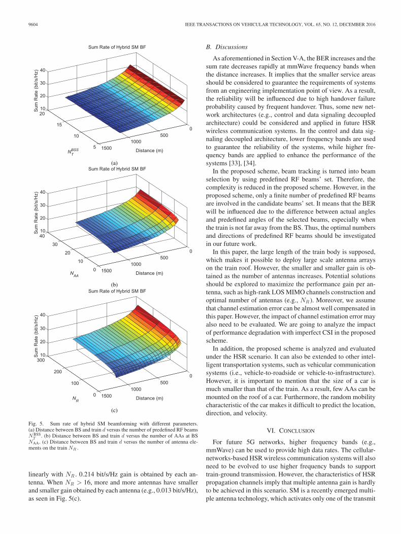
The influences of NBSST , NAA, and NR on sum rate perfor-
mance are shown in Fig. 5. The sum rate of the proposed schemeis not sensitive to NBSS
T but to some extent is sensitive to bothNAA and NR . It is also important to note that the performanceimprovement becomes smaller and smaller as NAA and NR in-crease. For example, when NR < 16, the sum rate increases
9604 IEEE TRANSACTIONS ON VEHICULAR TECHNOLOGY, VOL. 65, NO. 12, DECEMBER 2016
Fig. 5. Sum rate of hybrid SM beamforming with different parameters.(a) Distance between BS and train d versus the number of predefined RF beamsN BSS
T . (b) Distance between BS and train d versus the number of AAs at BSNAA. (c) Distance between BS and train d versus the number of antenna ele-ments on the train NR .
linearly with NR . 0.214 bit/s/Hz gain is obtained by each an-tenna. When NR > 16, more and more antennas have smallerand smaller gain obtained by each antenna (e.g., 0.013 bit/s/Hz),as seen in Fig. 5(c).
B. Discussions
As aforementioned in Section V-A, the BER increases and thesum rate decreases rapidly at mmWave frequency bands whenthe distance increases. It implies that the smaller service areasshould be considered to guarantee the requirements of systemsfrom an engineering implementation point of view. As a result,the reliability will be influenced due to high handover failureprobability caused by frequent handover. Thus, some new net-work architectures (e.g., control and data signaling decoupledarchitecture) could be considered and applied in future HSRwireless communication systems. In the control and data sig-naling decoupled architecture, lower frequency bands are usedto guarantee the reliability of the systems, while higher fre-quency bands are applied to enhance the performance of thesystems [33], [34].
In the proposed scheme, beam tracking is turned into beamselection by using predefined RF beams’ set. Therefore, thecomplexity is reduced in the proposed scheme. However, in theproposed scheme, only a finite number of predefined RF beamsare involved in the candidate beams’ set. It means that the BERwill be influenced due to the difference between actual anglesand predefined angles of the selected beams, especially whenthe train is not far away from the BS. Thus, the optimal numbersand directions of predefined RF beams should be investigatedin our future work.
In this paper, the large length of the train body is supposed,which makes it possible to deploy large scale antenna arrayson the train roof. However, the smaller and smaller gain is ob-tained as the number of antennas increases. Potential solutionsshould be explored to maximize the performance gain per an-tenna, such as high-rank LOS MIMO channels construction andoptimal number of antennas (e.g., NR ). Moreover, we assumethat channel estimation error can be almost well compensated inthis paper. However, the impact of channel estimation error mayalso need to be evaluated. We are going to analyze the impactof performance degradation with imperfect CSI in the proposedscheme.
In addition, the proposed scheme is analyzed and evaluatedunder the HSR scenario. It can also be extended to other intel-ligent transportation systems, such as vehicular communicationsystems (i.e., vehicle-to-roadside or vehicle-to-infrastructure).However, it is important to mention that the size of a car ismuch smaller than that of the train. As a result, few AAs can bemounted on the roof of a car. Furthermore, the random mobilitycharacteristic of the car makes it difficult to predict the location,direction, and velocity.
VI. CONCLUSION
For future 5G networks, higher frequency bands (e.g.,mmWave) can be used to provide high data rates. The cellular-networks-based HSR wireless communication systems will alsoneed to be evolved to use higher frequency bands to supporttrain-ground transmission. However, the characteristics of HSRpropagation channels imply that multiple antenna gain is hardlyto be achieved in this scenario. SM is a recently emerged multi-ple antenna technology, which activates only one of the transmit

CUI et al.: HYBRID SPATIAL MODULATION BEAMFORMING FOR MMWAVE RAILWAY COMMUNICATION SYSTEMS 9605
antennas during transmission. The properties of SM make ita potential way for HSR wireless communication systems. Inthis paper, a hybrid SM beamforming scheme is proposed atmmWave frequency bands under the HSR scenario. Theoreticalanalysis and numerical results indicate that a good compromisecan be achieved by the proposed scheme. Numerical results fur-ther show that the performance of the proposed scheme is notsensitive to the number of predefined RF beams, but it is to someextent sensitive to both AAs at BS and antenna elements in AAon the train. The challenges discussed in Section V-B will beour future work.
REFERENCES
[1] W. Roh et al., “Millimeter-wave beamforming as an enabling technologyfor 5G cellular communications: Theoretical feasibility and prototyperesults,” IEEE Commun. Mag., vol. 52, no. 2, pp. 106–113, Feb. 2014.
[2] B. Ai et al., “Future railway services-oriented mobile communicationsnetwork,” IEEE Commun. Mag., vol. 53, no. 10, pp. 78–85, Oct. 2015.
[3] E. G. Larsson, O. Edfors, F. Tufvesson, and T. L. Marzetta, “MassiveMIMO for next generation wireless systems,” IEEE Commun. Mag.,vol. 52, no. 2, pp. 186–195, Feb. 2014.
[4] F. Rusek et al., “Scaling up MIMO: Opportunities and challenges withvery large arrays,” IEEE Signal Process. Mag., vol. 30, no. 1, pp. 40–60,Jan. 2013.
[5] F. Boccardi, R. W. Heath Jr., A. Lozano, T. L. Marzetta, and P. Popovski,“Five disruptive technology directions for 5G,” IEEE Commun. Mag.,vol. 52, no. 2, pp. 74–80, Feb. 2014.
[6] B. H. Chen et al., “Channel characteristics in high-speed railway: A surveyof channel propagation properties,” IEEE Veh. Technol. Mag., vol. 10,no. 2, pp. 67–78, Jun. 2015.
[7] R. Y. Mesleh, H. Haas, S. Sinanovic, C. W. Ahn, and S. Yun, “Spatialmodulation,” IEEE Trans. Veh. Technol., vol. 57, no. 4, pp. 2228–2241,Jul. 2008.
[8] S. Wang, Y. Li, and J. Wang, “Multiuser detection in massive spatialmodulation MIMO with low-resolution ADCs,” IEEE Trans. WirelessCommun., vol. 14, no. 4, pp. 2156–2168, Apr. 2015.
[9] J. Zhang, Y. Wang, J. Zhang, and L. Ding, “Performance of spatial modula-tion with constant transmitted power under LOS and NLOS scenarios,” inProc. IEEE Int. Conf. Commun., London, U.K., Jun. 2015, pp. 2750–2755.
[10] Y. Cui and X. Fang, “Performance analysis of massive spatial modulationMIMO in high speed railway,” IEEE Trans. Veh. Technol., to be published,doi: 10.1109/TVT.2016.2518710.
[11] M. Koca and H. Sari, “Performance of spatial modulation over correlatedfading channels with channel estimation errors,” in Proc. IEEE WirelessCommun. Netw. Conf., Shanghai, China, Apr. 2013, pp. 3937–3942.
[12] M. Koca and H. Sari, “Performance analysis of spatial modulation overcorrelated fading channels,” in Proc. IEEE Veh. Technol. Conf. Fall,Quebec City, Canada, Sep. 2012, pp. 1–5.
[13] M. Di Renzo and H. Haas, “Space shift keying (SSK-) MIMO over corre-lated rician fading channels: Performance analysis and a new method fortransmit-diversity,” IEEE Trans. Commun., vol. 59, no. 1, pp. 116–129,Jan. 2011.
[14] C. Li, Y. Huang, M. Di Renzo, J. Wang, and Y. Cheng, “Low-complexityML detection for spatial modulation MIMO with APSK constellation,”IEEE Trans. Veh. Technol., vol. 64, no. 9, pp. 4315–4321, Sep. 2015.
[15] S. Wang, Y. Li, M. Zhao, and J. Wang, “Energy-efficient and low-complexity uplink transceiver for massive spatial modulation MIMO,”IEEE Trans. Veh. Technol., vol. 64, no. 10, pp. 4617–4632, Oct. 2015.
[16] A. Garcia-Rodriguez and C. Masouros, “Low-complexity compressivesensing detection for spatial modulation in large-scale multiple ac-cess channels,” IEEE Trans. Commun., vol. 63, no. 7, pp. 2565–2579,Jul. 2015.
[17] A. Younis et al., “Performance of spatial modulation using measured real-world channels,” in Proc. IEEE Veh. Technol. Conf. Fall, Las Vegas, NV,USA, Sep. 2013, pp. 1–5.
[18] N. Serafimovski et al., “Practical implementation of spatial modulation,”IEEE Trans. Veh. Technol., vol. 62, no. 9, pp. 4511–4523, Nov. 2013.
[19] J. Zhang, Y. Wang, L. Ding, and N. Zhang, “Bit error probability ofspatial modulation over measured indoor channels,” IEEE Trans. WirelessCommun., vol. 13, no. 3, pp. 1380–1387, Mar. 2014.
[20] Y. Fu et al., “A performance study of spatial modulation systems undervehicle-to-vehicle channel models,” in Proc. IEEE Veh. Technol. Conf.Spring, Seoul, South Korea, May 2014, pp. 1–5.
[21] M. Zhang, X. Cheng, and L. Yang, “Differential spatial modulation inV2X,” in Proc. IEEE Eur. Conf. Antennas Propag., Lisbon, Portugal,Apr. 2015, pp. 1–5.
[22] P. Yang, M. Di Renzo, Y. Xiao, S. Li, and L. Hanzo, “Design guide-lines for spatial modulation,” IEEE Commun. Surveys Tut., vol. 17, no. 1,pp. 6–26, Mar. 2015.
[23] T. Kim et al., “Tens of Gbps support with mmWave beamforming systemsfor next generation communications,” in Proc. IEEE Global Commun.Conf, Atlanta, GA, USA, Dec. 2013, pp. 3685–3690.
[24] A. Alkhateeb, O. El Ayach, G. Leus, and R. W. Heath, “Hybrid precodingfor millimeter wave cellular systems with partial channel knowledge,” inProc. IEEE Inf. Theory Appl. Workshop, San Diego, CA, USA, Feb. 2013,pp. 1–5.
[25] C. Kim, T. Kim, and J. Y. Seol, “Multi-beam transmission diversity withhybrid beamforming for MIMO-OFDM systems,” in Proc. IEEE Globe-com Workshop, Atlanta, GA, USA, Dec. 2013, pp. 61–65.
[26] C. Kim, J. Son, T. Kim, and J. Seol, “On the hybrid beamformingwith shared array antenna for mmWave MIMO-OFDM systems,” inProc. IEEE Wireless Commun. Netw. Conf., Istanbul, Turkey, April 2014,pp. 335–340.
[27] O. E. Ayach, S. Rajagopal, S. Abu-Surra, Z. Pi, and R. W. Heath, “Spa-tially sparse precoding in millimeter wave MIMO systems,” IEEE Trans.Wireless Commun., vol. 13, no. 3, pp. 1499–1513, Mar. 2014.
[28] A. Alkhateeb, G. Leus, and R. W. Heath, “Limited feedback hybrid pre-coding for multi-user millimeter wave systems,” IEEE Trans. WirelessCommun., vol. 14, no. 11, pp. 6481–6494, Nov. 2015.
[29] N. Aboutorab, W. Hardjawana, and B. Vucetic, “A new iterative doppler-assisted channel estimation joint with parallel ICI cancellation for high-mobility MIMO-OFDM systems,” IEEE Trans. Veh. Technol., vol. 61,no. 4, pp. 1577–1589, May 2012.
[30] C. Jiao, Z. Zhang, H. Zhang, L. Zhu, and C. Zhong, “A sequential antenna-hopping scheme for high mobility MIMO communications,” in Proc. IEEEInt. Conf. Commun., London, U.K., Jun. 2015, pp. 4984–4989.
[31] X. Ren, W. Chen, and M. X. Tao, “Position-Based compressed channel es-timation and pilot design for high-mobility OFDM systems,” IEEE Trans.Veh. Technol., vol. 64, no. 5, pp. 1918–1929, May 2015.
[32] M. Cheng and X. Fang, “Location information-assisted opportunisticbeamforming in LTE system for high-speed railway,” EURASIP J. Wire-less Commun. Netw., vol. 2012, no. 210, pp. 1–7, Jul. 2012.
[33] L. Yan, X. Fang, and Y. Fang, “Control and data signaling decoupledarchitecture for railway wireless networks,” IEEE Wireless Commun.,vol. 22, no. 1, pp. 103–111, Feb. 2015.
[34] H. Song, X. Fang, and L. Yan, “Handover scheme for 5G C/U plane splitheterogeneous network in high-speed railway,” IEEE Trans. Veh. Technol.,vol. 63, no. 9, pp. 4633–4646, Nov. 2014.
[35] J. Moreno, J. Riera, L. Haro, and C. Rodriguez, “A survey on futurerailway radio communications services: Challenges and opportunities,”IEEE Commun. Mag., vol. 53, no. 10, pp. 62–68, Oct. 2015.
[36] J. Li, L. Tian, Y. Zhou, and J. Shi, “An adaptive handover trigger schemefor wireless communications on high speed rail,” in Proc. IEEE Int. Conf.Commun., Ottawa, ON, Canada, Jun. 2012, pp. 5185–5189.
[37] X. Ren, M. Tao, and W. Chen, “Compressed channel estimation withposition-based ICI elimination for high-mobility SIMO-OFDM sys-tems,” IEEE Trans. Veh. Technol., vol. 65, no. 8, pp. 6204–6216,Aug. 2016.
[38] R. He et al., “A measurement-based stochastic model for high-speedrailway channels,” IEEE Trans. Intell. Transp. Syst., vol. 16, no. 3,pp. 1120–1135, Jun. 2015.
[39] A. Ghazal, C. Wang, B. Ai, D. Yuan, and H. Haas, “A nonstationary wide-band MIMO channel model for high-mobility intelligent transportationsystems,” IEEE Trans. Intell. Transp. Syst., vol. 16, no. 2, pp. 885–897,Apr. 2015.
[40] L. Liu, C. Tao, R. Sun, H. Chen, and Z. Lin, “Non-stationary channelcharacterization for high-speed railway under viaduct scenarios,” ChinaSci. Bull., vol. 59, no. 35, pp. 4988–4998, Dec. 2014.
[41] L. Liu, C. Tao, R. Sun, H. Chen, and Z. Lin, “Markov chain based channelcharacterization for high speed railway in viaduct scenarios,” in Proc.IEEE Int. Conf. Commun., Sydney, NSW, Australia, Jun. 2014, pp. 5896–5901.
[42] M. Cheng, S. Yang, and X. Fang, “Adaptive antenna-activation basedbeamforming for large-scale MIMO communication systems of high speedrailway,” China Commun., vol. 13, no. 9, pp. 12–23, Sep. 2016.

9606 IEEE TRANSACTIONS ON VEHICULAR TECHNOLOGY, VOL. 65, NO. 12, DECEMBER 2016
[43] Y. Cui and X. Fang, “A massive MIMO-based adaptive multi-stream beam-forming scheme for high-speed railway,” EURASIP J. Wireless Commun.Netw., vol. 2015, no. 259, pp. 1–8, Dec. 2015.
[44] L. Zhu, F. R. Yu, B. Ning, and T. Tang, “Handoff performance improve-ments in MIMO-enabled communication-based train control systems,”IEEE Trans. Intell. Transp. Syst., vol. 13, no. 2, pp. 582–593, Jun. 2012.
[45] L. Zhu, F. R. Yu, B. Ning, and T. Tang, “Cross-layer handoff design inMIMO-enabled WLANs for communication-based train control (CBTC)systems,” IEEE J. Sel. Areas Commun., vol. 30, no. 4, pp. 719–728,May 2012.
[46] M. R. Akdeniz et al., “Millimeter wave channel modeling and cellu-lar capacity evaluation,” IEEE J. Sel. Areas Commun., vol. 32, no. 6,pp. 1164–1179, Jun. 2014.
[47] E. Telatar, “Capacity of multi-antenna Gaussian channels,” Eur. Trans.Telecommun., vol. 10, no. 6, pp. 585–595, Nov./Dec. 1999.
[48] R. Rajashekar, K. V. S. Hari, and L. Hanzo, “Reduced-complexity MLdetection and capacity-optimized training for spatial modulation systems,”IEEE Trans. Commun., vol. 62, no. 1, pp. 112–125, Jan. 2014.
[49] J. Jeganathan, A. Ghrayeb, and L. Szczecinski, “Spatial modulation: Op-timal detection and performance analysis,” IEEE Commun. Lett., vol. 12,no. 8, pp. 545–547, Aug. 2008.
[50] J. G. Proakis and M. Salehi, Digital Communications, 5th ed. New York,NY, USA: McGraw-Hill, 2008.
[51] M. Di Renzo and H. Haas, “Performance analysis of spatial modula-tion,” in Proc. 5th Int. ICST Conf. Commun. Netw. China, Beijing, China,Aug. 2010, pp. 1–7.
[52] J. Kim and I. Kim, “Distributed antenna system-based millimeter-wavemobile broadband communication system for high speed trains,” inProc. IEEE Int. Conf. ICT Convergence, Jeju, South Korea, Oct. 2013,pp. 218–222.
Yaping Cui was born in Henan, China, in 1986. Hereceived the B.E. degree from PLA Information Engi-neering University, in 2008, and the M.E. degree fromSouthwest Jiaotong University, Chengdu, China, in2011, where he is currently working toward the Ph.D.degree with the Key Laboratory of Information Cod-ing and Transmission.
His research interests include millimeter wavecommunications, multiple antenna technologies, andsmart antennas for high-speed railways.
Xuming Fang (M’00–SM’16) received the B.E. de-gree in electrical engineering in 1984, the M.E. degreein computer engineering in 1989, and the Ph.D. de-gree in communication engineering in 1999, all fromSouthwest Jiaotong University, Chengdu, China.
In September 1984, he was a Faculty Memberin the Department of Electrical Engineering, TongjiUniversity, Shanghai, China. He then joined the KeyLaboratory of Information Coding and Transmis-sion, School of Information Science and Technology,Southwest Jiaotong University, where he has been a
Professor since 2001 and the Chair of the Department of Communication En-gineering since 2006. He held visiting positions with the Institute of RailwayTechnology, Technical University Berlin, Berlin, Germany, in 1998 and 1999and with the Center for Advanced Telecommunication Systems and Services,University of Texas at Dallas, Richardson, TX, USA, in 2000 and 2001. He hasto his credit around 200 high-quality research papers in journals and confer-ence publications. He is the author or the coauthor of five books and textbooks.His research interests include wireless broadband access control, radio resourcemanagement, multihop relay networks, and broadband wireless access for high-speed railways.
Dr. Fang is an Editor of the IEEE TRANSACTION ON VEHICULAR TECH-NOLOGY, Journal of Electronics and Information, and the Chair of the IEEEVehicular Technology Society Chengdu Chapter.
Li Yan received the B.E. degree in communica-tion engineering from Southwest Jiaotong University,Chengdu, China, where she is currently working to-ward the Ph.D. degree with the Key Laboratory ofInformation Coding and Transmission, School of In-formation Science and Technology.
Her research interests include handover, networkarchitecture, and reliable wireless communication forhigh-speed railways.