ieee transactions on robotics, vol. 22, no. 5, october 2006...
TRANSCRIPT

IEEE TRANSACTIONS ON ROBOTICS, VOL. 22, NO. 5, OCTOBER 2006 987
Real-Time Adaptive Control forHaptic Telemanipulation With
Kalman Active ObserversRui Cortesão, Member, IEEE, Jaeheung Park, Student Member, IEEE, and Oussama Khatib, Fellow, IEEE
Abstract—This paper discusses robotic telemanipulation withKalman active observers and online stiffness estimation. Opera-tional space techniques, feedback linearization, discrete state spacemethods, augmented states, and stochastic design are used to con-trol a robotic manipulator with a haptic device. Stiffness estimationonly based on force data (measured, desired, and estimated forces)is proposed, avoiding explicit position information. Stability androbustness to stiffness errors are discussed, as well as real-timeadaptation techniques. Telepresence is analyzed. Experimentsshow high performance in contact with soft and hard surfaces.
Index Terms—Compliant motion control, haptics, Kalman ac-tive observers (AOBs), robotic manipulation, stiffness estimation,telepresence.
I. INTRODUCTION
TOUCH sensations are essential for many telemanipulationtasks. Haptic devices integrated in robotic systems can pro-
vide the right framework to execute contact tasks with high per-formance. Such systems can be applied not only for industrialpurposes [32], but also in the field of service robotics [14]. Typ-ical applications include remote handling in dangerous environ-ments [21], telesurgery [35], and interaction with virtual objects[18]. Telepresence is reached if the haptic feeling representswell the real contact. Augmented reality through high-fidelityforce feedback can result in the emergence of new manipula-tion techniques, extending human dexterity.
Physical limits (e.g., time delay, bandwidth, and samplingtime) and robustness requirements of the robotic setup have to bemapped into an optimal haptic feeling, which is coded into thecontrol architecture. To design a controller, approximate and lin-earized models are frequently considered, allowing the extensiveand rich theoryof linear systems to be applied.A simple and mod-ular control synthesis can be achieved by decentralized control,decoupling the overall system into several subsystems, in whichautonomous local controllers are designed. Compliant motion
Manuscript received October 13, 2005. This paper was recommended for pub-lication by Associate Editor E. Papadopoulos and Editor K. Lynch upon eval-uation of the reviewers’ comments. This paper is an expanded version of pa-pers published in the Proceedings of the International Conference on IntelligentRobots and Systems, 2003, pp. 2938–2943; the Proceedings of the InternationalConference on Intelligent Robots and Systems, 2005, pp. 3146–3151; and theProceedings of the International Conference on Advanced Robotics, 2003, pp.513–519.
R. Cortesão is with the Institute of Systems and Robotics, University ofCoimbra, 3030 Coimbra, Portugal (e-mail: [email protected]).
J. Park and O. Khatib are with the Robotics Group, Stanford University,Stanford, CA 94305-9010 USA (e-mail: [email protected];[email protected]).
Digital Object Identifier 10.1109/TRO.2006.878787
tasks require special attention [34], since the task constraintschange abruptly and the model parameters may have wide varia-tions, particularly for very stiff and unstructured environments.
The literature on robotic teleoperation is very extensive.Several control techniques have been presented to cope withuncertainty, time delay, master/slave models, robustness, andtelepresence. Zhu and Salcudean [38] proposed adaptive mo-tion/force control robust to time delays, taking into accountnonlinear rigid body dynamics of master/slave systems. Ryuand Kwon [33] proposed adaptive bilateral control withoutestimating environment parameters. Kim et al. [24] suggestedlocal force feedback (shared compliant control) to provide acompliant slave robot for stiff contact. Adaptive techniquesbased on passive systems have been discussed by Hannafordand Ryu [19]. Simple architectures such as position–force1
and position–position2 have limited performance [13], [26].Various implementations have used additional information (suchas forces and accelerations) to achieve better telepresence [26],[28], [37]. Hashtrudi-Zaad and Salcudean [20] have shown thatperfect telepresence can be obtained under ideal conditions usinglocal force feedback with a three-channel architecture. Stabilityanalysis has been done by Colgate and Hogan [5] using thepassivity theory, and by Flemmer et al. [17] based on closed-looptransfer functions. Lawrence [26] analyzed the tradeoff betweenstability and telepresence, proposing a unified four-channelcontrol architecture based on force and position signals. Kalmanactive observers (AOBs), introduced in [6] and [39], have beenapplied in several applications, such as force control of roboticmanipulators [8], [9], [30], haptic manipulation [11], [12], [29],humanoids [31], and mobile systems [2], [4], [7], [27].
This paper describes a control architecture for haptic tele-manipulation with AOBs and online stiffness estimation. Thebackground motivation of this study is robotic-assisted surgery,where the surgeon and robot work in the same room. Therefore,the system time delay is small and the contact parameters canbe lumped into a Cartesian stiffness. The teleoperation schemekeeps a position–position architecture, in which force commandsare generated through virtual coupling. The main differences ofour approach with respect to previous work are given here.
1) The slave side has a decentralized3 adaptive compliant mo-tion controller with Kalman AOBs. The AOB reformulatesthe Kalman filter to accomplish model-reference adaptive
1Position commands on the master side and force commands on the slaveside.
2Only position commands.3In this paper, decentralized control means an independent control for each
Cartesian dimension.
1552-3098/$20.00 © 2006 IEEE

988 IEEE TRANSACTIONS ON ROBOTICS, VOL. 22, NO. 5, OCTOBER 2006
Fig. 1. System setup. (a) Phantom device controlled by a human. (b) PUMArobot. Soft and stiff objects belong to the PUMA workspace.
control, based on a desired closed-loop model, state aug-mentation, and stochastic design. The system stiffness en-ters in the AOB design, enabling consistent force responses(i.e., the same closed-loop dynamics) independent of con-tact objects.
2) Online stiffness estimation only based on force data (mea-sured, desired, and estimated forces), avoiding explicit po-sition information.
This paper is organized as follows. After the description ofthe system setup in Section II, the decentralized control archi-tecture is presented in Section III. The AOB design is introducedin Section IV, including the AOB algorithm, estimation strate-gies, and control design. Stability and robustness to stiffnessmismatches are discussed in Section V, including preliminaryexperiments on the slave side. Section VI describes the tele-operation scheme, analyzing telepresence and stability in freespace and contact. The algorithm for online stiffness estimationis presented in Section VII. Haptic manipulation experimentsare addressed in Section VIII. The conclusions are summarizedin Section IX.
II. SYSTEM SETUP
Fig. 1 shows the master and slave stations. The master stationis a Phantom 1.0A which has six degrees of freedom (DOFs)and three motors for the first joints. The haptic device is con-trolled by a quadric-processor Pentium Pro at 200 MHz. Theslave robot is a PUMA 560, which has a stiff JR3 force sensorat the end-effector. The PUMA has six DOFs and is connectedto a computer (Pentium II at 333 MHz with QNX real-time OS)
TABLE IOBJECT STIFFNESSES. K AND K DATA
through a TRC205 controller and a ServoToGo board. The con-trol of the orientation is not considered in this setup. The PUMArobot is controlled so that it has the same orientation in a globalframe. A local area network is used to connect both stations.The sampling time is ms. The system time delay wasobtained experimentally. It is
ms (1)
The working space has objects with different stiffnesses. Whenthe robot is manipulating, the system stiffness is a functionof the environment, the JR3 sensor, and the PUMA robot. If theenvironment is soft, is approximately given by the environ-ment stiffness. For stiff environments, the computation of isnot trivial.
Table I presents experimental and nominalvalues of the system stiffness.4 The relation between and
is
(2)
where is the error associated with .
III. DECENTRALIZED CONTROL ARCHITECTURE
Here, we describe the decentralized control architecture ap-plied in our system, based on operational space, feedback lin-earization, and state-space techniques.
A. Manipulator Dynamics
Given a set of generalized coordinates (usually, joint anglesfor revolute joints) describing the robot’s pose, the well-knownrobot dynamics is given by
(3)
where is the mass matrix, is the vector of Coriolis andcentripetal forces, is the gravity term, and is the gener-alized torque acting on . For a nonredundant manipulator, (3)can be represented in the Cartesian domain by
(4)
with
(5)
(6)
(7)
(8)
where , , and are, respectively, the Jacobian matrix, Carte-sian position (operational space), and Cartesian force [23]. An
4The nominal values are the ones used in the control design. The results ofK for the sponge were achieved offline.
CORTESÃO et al.: REAL-TIME ADAPTIVE CONTROL FOR HAPTIC TELEMANIPULATION WITH KALMAN AOBS 989
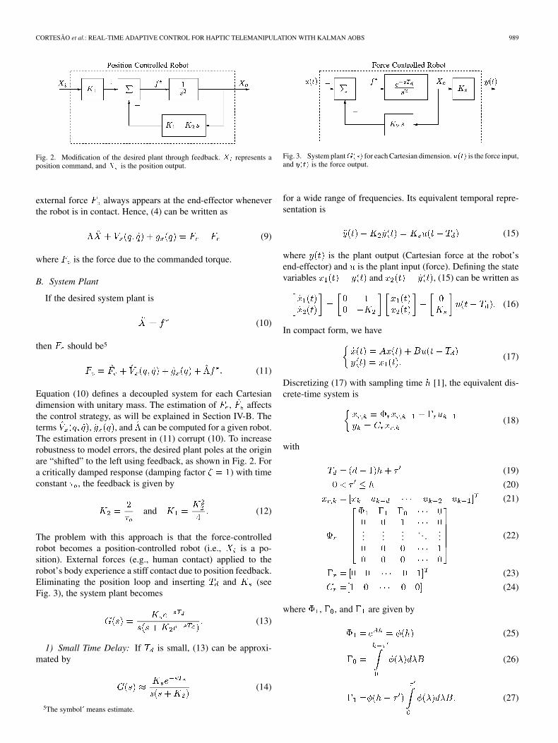
Fig. 2. Modification of the desired plant through feedback. X represents aposition command, and X is the position output.
external force always appears at the end-effector wheneverthe robot is in contact. Hence, (4) can be written as
(9)
where is the force due to the commanded torque.
B. System Plant
If the desired system plant is
(10)
then should be5
(11)
Equation (10) defines a decoupled system for each Cartesiandimension with unitary mass. The estimation of , affectsthe control strategy, as will be explained in Section IV-B. Theterms , , and can be computed for a given robot.The estimation errors present in (11) corrupt (10). To increaserobustness to model errors, the desired plant poles at the originare “shifted” to the left using feedback, as shown in Fig. 2. Fora critically damped response (damping factor ) with timeconstant , the feedback is given by
and (12)
The problem with this approach is that the force-controlledrobot becomes a position-controlled robot (i.e., is a po-sition). External forces (e.g., human contact) applied to therobot’s body experience a stiff contact due to position feedback.Eliminating the position loop and inserting and (seeFig. 3), the system plant becomes
(13)
1) Small Time Delay: If is small, (13) can be approxi-mated by
(14)
5The symbol^means estimate.
Fig. 3. System plantG(s) for each Cartesian dimension.u(t) is the force input,and y(t) is the force output.
for a wide range of frequencies. Its equivalent temporal repre-sentation is
(15)
where is the plant output (Cartesian force at the robot’send-effector) and is the plant input (force). Defining the statevariables and , (15) can be written as
(16)
In compact form, we have
(17)
Discretizing (17) with sampling time [1], the equivalent dis-crete-time system is
(18)
with
(19)
(20)
(21)
......
.... . .
... (22)
(23)
(24)
where , , and are given by
(25)
(26)
(27)
990 IEEE TRANSACTIONS ON ROBOTICS, VOL. 22, NO. 5, OCTOBER 2006
has two states representing the force and force derivative.The other states appear due to . The continuous state transi-tion and command matrices are
and (28)
From (28), the computation of , , and is straightforward.2) Bigger Time Delays: If is not small enough, the term
(29)
of (13) can be approximated by an adequate truncated Taylorseries, increasing the system order. The same procedure of thesmall time delay can then be applied (not addressed in thispaper).
IV. AOB DESIGN
When some parameters of a controlled process have widevariations and are poorly known, high-performance controllersrequire adaptive control techniques. Landau [25] has definedadaptive systems as systems in which the adaptation mecha-nism modifies the parameters of the adjustable system or gener-ates an auxiliary input to maintain a given index of performancebounded to acceptable values. To accomplish model-referenceadaptive control, the AOB reformulates the Kalman filter, basedon the following.
1) A desired closed-loop system (reference model) that entersin the state estimation.
2) An extra equation (auxiliary input) to estimate an equiv-alent disturbance referred to the system input, due to un-modeled terms including higher order dynamics, parametermismatches, and unknown disturbances. An active state(extra state) is introduced to describe the equivalent distur-bance. Its estimate performs the compensation action.
is described by (the same equation used in [10] to esti-mate unknown functions)
(30)
The stochastic equation (30) says that the th-order deriva-tive (or th-order evolution) of is randomly distributed.
is a Gaussian variable with zero mean. If
(31)
then (30) is a deterministic model for any disturbancethat has its th derivative equal to zero. In this way, thestochastic information present in gives more flexi-bility to , since its evolutionary model is not rigid.
3) The stochastic design of the Kalman matrices for the AOBcontext.
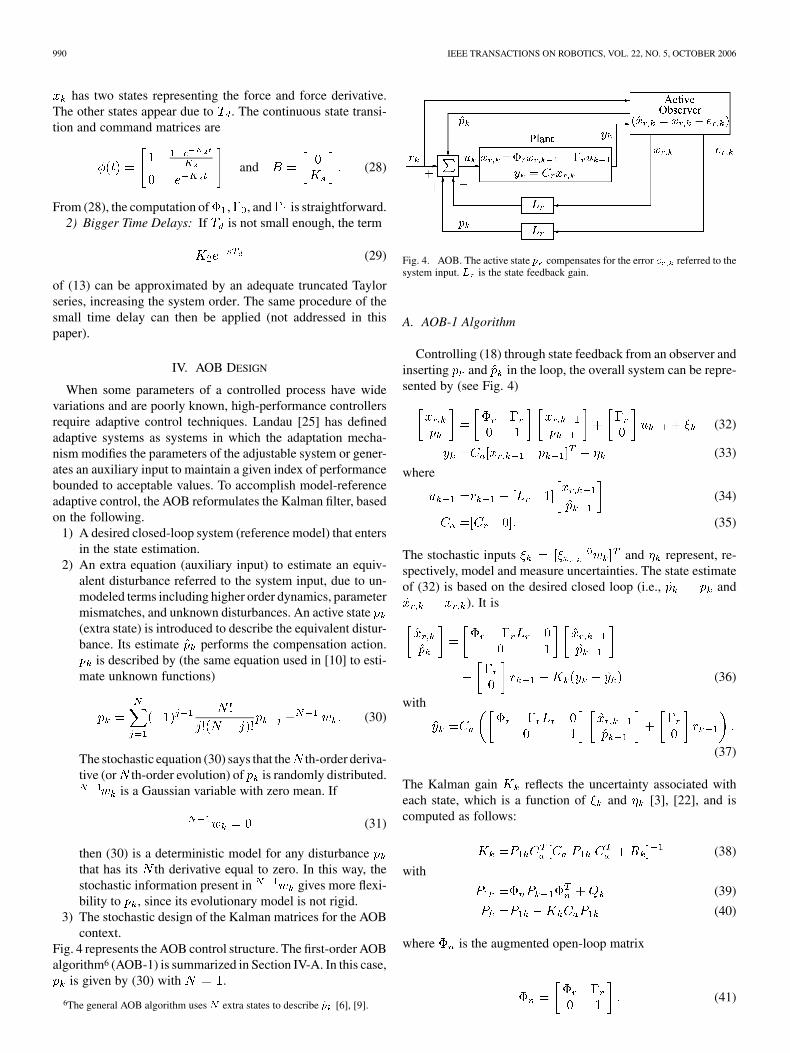
Fig. 4 represents the AOB control structure. The first-order AOBalgorithm6 (AOB-1) is summarized in Section IV-A. In this case,
is given by (30) with .
6The general AOB algorithm uses N extra states to describe p̂ [6], [9].
Fig. 4. AOB. The active state p̂ compensates for the error e referred to thesystem input. L is the state feedback gain.
A. AOB-1 Algorithm
Controlling (18) through state feedback from an observer andinserting and in the loop, the overall system can be repre-sented by (see Fig. 4)
(32)
(33)
where
(34)
(35)
The stochastic inputs and represent, re-spectively, model and measure uncertainties. The state estimateof (32) is based on the desired closed loop (i.e., and
). It is
(36)
with
(37)
The Kalman gain reflects the uncertainty associated witheach state, which is a function of and [3], [22], and iscomputed as follows:
(38)
with
(39)
(40)
where is the augmented open-loop matrix
(41)
CORTESÃO et al.: REAL-TIME ADAPTIVE CONTROL FOR HAPTIC TELEMANIPULATION WITH KALMAN AOBS 991
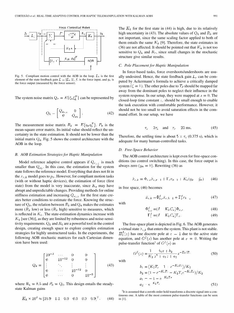
Fig. 5. Compliant motion control with the AOB in the loop. L is the firstelement of the state feedback gain L = [L 1], f is the force input, and y isthe force output (measured by the force sensor).
The system noise matrix can be represented by
(42)
The measurement noise matrix . is themean-square error matrix. Its initial value should reflect the un-certainty in the state estimation. It should not be lower than theinitial matrix . Fig. 5 shows the control architecture with theAOB in the loop.
B. AOB Estimation Strategies for Haptic Manipulation
Model reference adaptive control appears if is muchsmaller than . In this case, the estimation for the systemstate follows the reference model. Everything that does not fit inthe model goes to . However, for compliant motion tasks(with or without haptic devices), the estimation of force (firststate) from the model is very inaccurate, since may haveabrupt and unpredictable changes. Providing methods for onlinestiffness estimation and increasing for the first state cre-ates better conditions to estimate the force. Knowing the struc-ture of , the relation between and makes the estimatesmore ( low) or less ( high) sensitive to measures, whichis reflected in . The state-estimation dynamics increase with
[see (36)], as they are limited by robustness and noise-sensi-tivity requirements. and are a powerful tool in the controldesign, creating enough space to explore complex estimationstrategies for highly unstructured tasks. In the experiments, thefollowing AOB stochastic matrices for each Cartesian dimen-sion have been used:
.... . .
...... (43)
where and . This design entails the steady-state Kalman gains
(44)
The for the first state in (44) is high, due to its relativelyhigh uncertainty in (43). The absolute values of and arenot important, since the same scaling factor applied to both ofthem entails the same [9]. Therefore, the state estimates in(36) are not affected. It should be pointed out that is not toosensitive to and , since small changes in the stochasticstructure give similar results.
C. Pole Placement for Haptic Manipulation
In force-based tasks, force overshoots/undershoots are usu-ally undesired. Hence, the state feedback gain can be com-puted by Ackermann’s formula to achieve a critically dampedsystem . The other poles due to should be mapped faraway from the dominant poles to neglect their influence in thesystem response. In our setup, they were mapped at . Theclosed-loop time constant should be small enough to enablethe task execution with comfortable performance. However, itshould not be too small to avoid saturation effects in the com-mand effort. In our setup, we have
and ms (45)
Therefore, the settling time is about (0.375 s), which isadequate for many human-controlled tasks.
D. Free-Space Behavior
The AOB control architecture is kept even for free-space con-ditions (no control switching). In this case, the force output isalways zero . Rewriting (36) as
(46)
in free space, (46) becomes
(47)
with
(48)
(49)
The free-space plant is depicted in Fig. 6. The AOB generatesa virtual state that enters the system. This plant is not stable.
has one discrete pole at due to the active stateequation, and has another pole at . Writing thepulse-transfer function7 of as
(50)
with
(51)
7It is assumed that a zeroth-order hold transforms a discrete signal into a con-tinuous one. A table of the most common pulse-transfer functions can be seenin [1].

992 IEEE TRANSACTIONS ON ROBOTICS, VOL. 22, NO. 5, OCTOBER 2006
Fig. 6. Free-space plant. The AOB controller generates a virtual state that en-ters the system. This plant has one continuous pole at s = 0 and a discrete poleat z = 1.
Fig. 7. LTF computation with the AOB in the loop.
then the equivalent transfer function of the free-space plant, also including the preamplification of by , is
(52)
(53)
Stability of the whole system is achieved through the teleoper-ation architecture described in Section VI.
V. AOB STABILITY AND ROBUSTNESS
Here, we analyze relative stability of AOB-based controllersin the presence of model errors. The loop transfer function8
(LTF) of the control system has to be derived. A schematic rep-resentation of it is depicted in Fig. 7. Applying to the plantinput and considering all other inputs zero (necessary to com-pute the LTF), (32) and (33) can be written as
(54)
(55)
with
(56)
8The LTF is the product of the transfer functions of forward and feedbackloops. Special attention should be paid when observers are in the loop [15].
The real system matrix is equal to the nominal matrix (i.e.,the one used in the design) plus the unknown error due tounmodeled terms. Mathematically, we have
(57)
The AOB state estimate is9 of the form
(58)
with , , and . Definingthe estimation error as
(59)
then and can be written as
(60)
where
(61)
(62)
The LTF output is
(63)
The transfer function of the state-space equations (60) and (63)is the LTF, , which is given by
(64)
where and are the state transition and command matricesof (60), respectively, and is the identity matrix. Knowing
, it is straightforward to compute Nyquist/Bode plotsand the corresponding phase and gain margins.10 At verylow frequencies, noise statistics make no sense (everything is“static”). The LTF introduces one additional integrator as theAOB order increases, corresponding to the active state equation(30) when . Therefore, the system type increaseswith the AOB order, improving tracking capabilities, althoughthe relative stability decreases.
A. Robustness
In compliant motion tasks, it is important to analyze relativestability when there are stiffness mismatches. From (19), (20),and (1), and . Hence, from (26), .Moreover, given by (25) does not depend on . If there isa mismatch, is given by [see (27)]
(65)
9See (36) for r = 0.10In the Matlab environment, the LTF representation in state space or transfer
function is all that is needed to have Nyquist/Bode plots.

CORTESÃO et al.: REAL-TIME ADAPTIVE CONTROL FOR HAPTIC TELEMANIPULATION WITH KALMAN AOBS 993
Fig. 8. Robustness to stiffness errors. (a) Gain margin. (b) Phase margin. Sta-bility problems only arise from underestimated stiffness. The values of Kare in N/m. Simulation results.
From (22), we have
......
.... . .
... (66)
Knowing (41), we have
(67)
Using (60), stability can be analyzed based on the stiffnessmismatch. From Fig. 8, it can be inferred that overestimatingthe stiffness does not create stability problems (negative
values). Moreover, robustness increases with .For N/m, the control structure is stable11 up to
N/m. If N/m, the maximum stiffnessmismatch is about 400%. This robustness analysis establishesthe maximum mismatch between the real stiffness and the
11The full teleoperation scheme discussed in Section VI is not considered inthis analysis.
nominal one without losing stability, giving an upper bound tothe estimation error. Methods for online stiffness estimation areproposed in Section VII.
B. Real-Time Issues
This section analyzes properties of AOB-based controllers foronline stiffness adaptation. In haptic tasks, contact/noncontactstates with stiff objects are critical, since the stiffness changesare big. To achieve consistent force responses independent ofthe contact object, has to be estimated online to adapt theAOB accordingly.
1) Control Adaptation: The feedback gain of the con-troller can be easily adapted for new environment stiffnesseswithout a complete computation of Ackermann’s formula. It canbe shown [9] that for with corresponding feedback gains
(68)
if changes , then the new vector should be com-puted from
(69)The feedback gains of the state variables due to do notchange. Only a proportional factor needs to be computed toupdate for the “core state.”
2) State Estimation: When changes , the ma-trix changes to . Only two elements of this matrixhave to be recomputed. The Kalman gains are obtained on-line from (38)–(40). The state estimate of the AOB in (36) needsto be updated, reflecting the changes in , , and .
C. Free-Space to Stiff Contact Experiments
This section illustrates the AOB controller without stiffnessadaptation. The robot moves from free-space to stiff con-tact with a desk in the direction, keeping always6000 N/m. When the reference force changes from 0 to 5 N, therobot starts to accelerate due to the active state, till it reaches thedesk, where nearly 100 N are measured [see Fig. 9(a) and (c)].Taking a closer look at the impact data [see Fig. 9(c)], themeasured force is always negative, which means that the tran-sition from free space to stiff contact has no bouncing effects.While in contact, the force response follows a critically dampedresponse [see Fig. 9(a) and (d)], with a time constant that isbigger than expected [see (45)]. This means that the value for
is bigger than . The active state reflects this mismatch,increasing its value during the step input, helping the robot topush more in the -direction, as shown in Fig. 9(c), around 74 s.The position data cannot be used in a consistent way. Whenthe measured force changes smoothly from 5 to 10 N,the measured position does not change in the same way [seeFig. 9(d)], creating problems for online stiffness estimation.The force response drops about 3 N (around 74 s), keeping thesame position data. Additionally, a slight change in the forcemakes a relatively big change in the position. These effectsmake position measurements not recommended for online stiff-ness inference, motivating the exploration of adaptive controltechniques only based on force data.

994 IEEE TRANSACTIONS ON ROBOTICS, VOL. 22, NO. 5, OCTOBER 2006
Fig. 9. Experimental results of the AOB controller. Free-space to stiff contact (desk) in the z direction. (a) Force response. (b) Zoom of the impact data. (c) Activestate and position data. (d) Zoom of force and position responses. The position data in (b)–(d) were rescaled and shifted by a constant value to match the verticalscale.
Fig. 10. Teleoperation scheme. G (s) represents the PUMA robot, the AOBand the environment, and G (s) represents the master station, including thehuman arm and the haptic device.
VI. TELEOPERATION SCHEME
Fig. 10 illustrates the teleoperation scheme for each direc-tion in operational space. , , , and are the masterposition, slave position, position scaling, and force scaling, re-spectively. represents the slave station, including therobotic manipulator, the AOB, and the environment. canbe split into two functions, describing contact and free-spaceconditions. is the master station, which includes thehaptic device and the human arm. It can be represented by [36]
(70)
where , , and are, respectively, the mass, damping,and stiffness of the master station.12 This teleoperation scheme issimilar to a position–position architecture with some differences.
12K is mainly due to the human arm stiffness.
The input to the master and slave is the desired force , gener-ated by position errors through the virtual coupling . The AOBcommands the slave device to track with a desired dynamics.There is no force controller at the master station, which receives
scaled by . In the teleoperation experiments
N/m
(71)
A. Teleoperation in Contact
For the control design proposed in this paper, the desiredtransfer function while in contact is
(72)
which means that the force response is critically damped withtime constant , as discussed in Section IV-C.
1) Telepresence: The quality of the haptic feeling is analyzedby investigating the transfer function13 from the human forceto the master position [26]. Looking to Fig. 11, telepresence isachieved if is of form
(73)
13The Laplace transforms of x and f areX (s) and F (s), respectively.
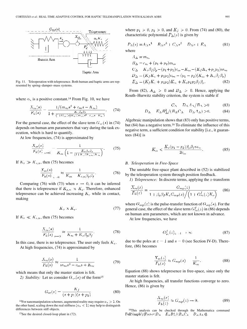
CORTESÃO et al.: REAL-TIME ADAPTIVE CONTROL FOR HAPTIC TELEMANIPULATION WITH KALMAN AOBS 995
Fig. 11. Teleoperation with telepresence. Both human and haptic arms are rep-resented by spring–damper–mass systems.
where is a positive constant.14 From Fig. 10, we have
(74)
For the general case, the effect of the slave term in (74)depends on human arm parameters that vary during the task ex-ecution, which is hard to quantify.
At low frequencies, (74) is approximated by
(75)
If , then (75) becomes
(76)
Comparing (76) with (73) when , it can be inferredthat there is telepresence if . Therefore, enhancedtelepresence can be achieved increasing while in contact,making
(77)
If , then (75) becomes
(78)
In this case, there is no telepresence. The user only feels .At high frequencies, (74) is approximated by
(79)
which means that only the master station is felt.2) Stability: Let us consider of the form15
(80)
14For nanomanipulation schemes, augmented reality may require� > 1. Onthe other hand, scaling down the real stiffness (� < 1) may help to distinguishdifferences between stiff objects.
15See the desired closed-loop plant in (72).
where , , and . From (74) and (80), thecharacteristic polynomial is given by
(81)
where
(82)
From (82), and . Hence, applying theRouth–Hurwitz stability criterion, the system is stable if
(83)
(84)
Algebraic manipulation shows that (83) only has positive terms,but (84) has a negative term.16 To eliminate the influence of thisnegative term, a sufficient condition for stability [i.e., it guaran-tees (84)] is
(85)
B. Teleoperation in Free-Space
The unstable free-space plant described in (52) is stabilizedby the teleoperation system through position feedback.
1) Telepresence: In discrete terms, applying the -transform
(86)
where is the pulse-transfer function of . For thegeneral case, the effect of the slave term in (86) dependson human arm parameters, which are not known in advance.
At low frequencies, we have
(87)
due to the poles at and (see Section IV-D). There-fore, (86) becomes
(88)
Equation (88) shows telepresence in free-space, since only themaster station is felt.
At high frequencies, all transfer functions converge to zero.Hence, (86) is given by
(89)
16This analysis can be checked through the Mathematica commandFullSimplify[Factor[D � E B =(B C �D A )]].
996 IEEE TRANSACTIONS ON ROBOTICS, VOL. 22, NO. 5, OCTOBER 2006
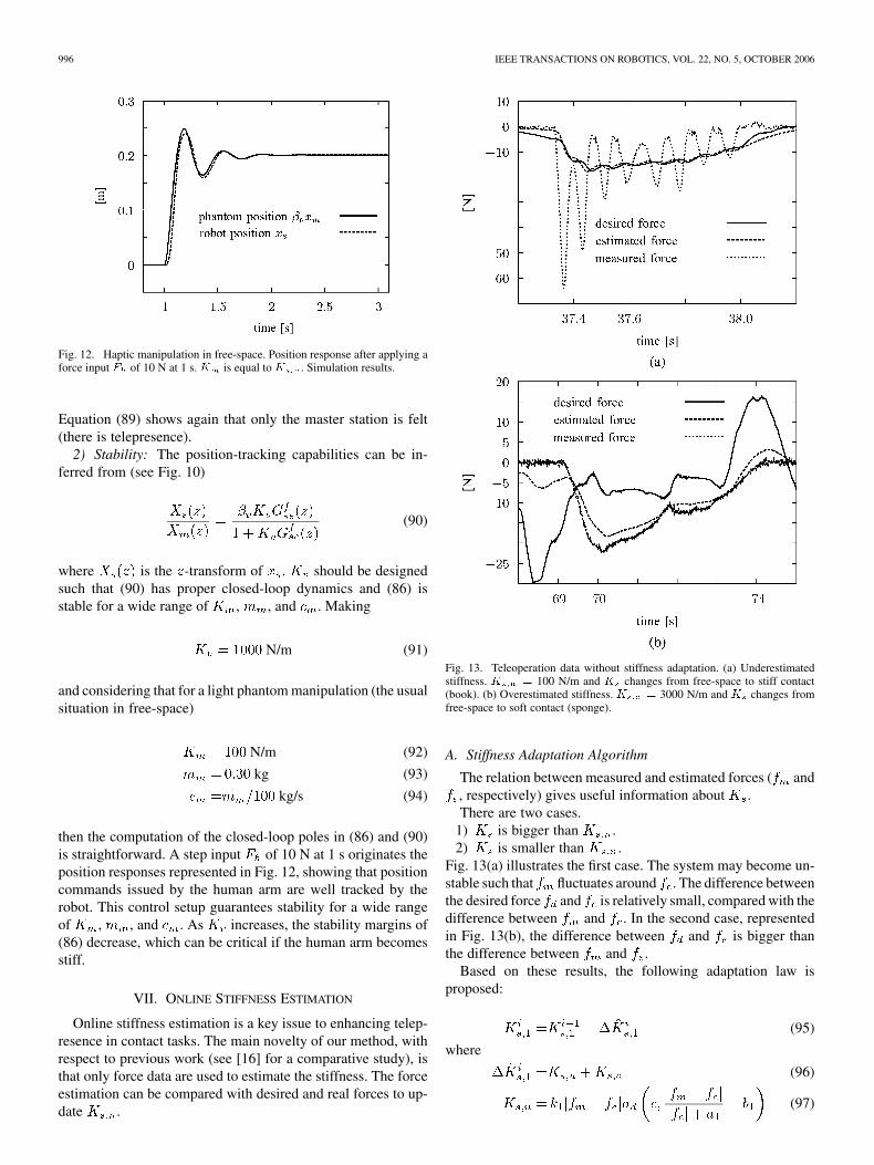
Fig. 12. Haptic manipulation in free-space. Position response after applying aforce input F of 10 N at 1 s.K is equal to K . Simulation results.
Equation (89) shows again that only the master station is felt(there is telepresence).
2) Stability: The position-tracking capabilities can be in-ferred from (see Fig. 10)
(90)
where is the -transform of . should be designedsuch that (90) has proper closed-loop dynamics and (86) isstable for a wide range of , , and . Making
N/m (91)
and considering that for a light phantom manipulation (the usualsituation in free-space)
N/m (92)
kg (93)
kg/s (94)
then the computation of the closed-loop poles in (86) and (90)is straightforward. A step input of 10 N at 1 s originates theposition responses represented in Fig. 12, showing that positioncommands issued by the human arm are well tracked by therobot. This control setup guarantees stability for a wide rangeof , , and . As increases, the stability margins of(86) decrease, which can be critical if the human arm becomesstiff.
VII. ONLINE STIFFNESS ESTIMATION
Online stiffness estimation is a key issue to enhancing telep-resence in contact tasks. The main novelty of our method, withrespect to previous work (see [16] for a comparative study), isthat only force data are used to estimate the stiffness. The forceestimation can be compared with desired and real forces to up-date .
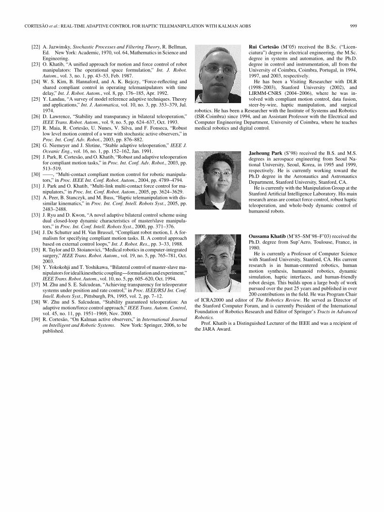
Fig. 13. Teleoperation data without stiffness adaptation. (a) Underestimatedstiffness. K = 100 N/m and K changes from free-space to stiff contact(book). (b) Overestimated stiffness. K = 3000 N/m and K changes fromfree-space to soft contact (sponge).
A. Stiffness Adaptation Algorithm
The relation between measured and estimated forces ( and, respectively) gives useful information about .There are two cases.
1) is bigger than .2) is smaller than .
Fig. 13(a) illustrates the first case. The system may become un-stable such that fluctuates around . The difference betweenthe desired force and is relatively small, compared with thedifference between and . In the second case, representedin Fig. 13(b), the difference between and is bigger thanthe difference between and .
Based on these results, the following adaptation law isproposed:
(95)
where
(96)
(97)

CORTESÃO et al.: REAL-TIME ADAPTIVE CONTROL FOR HAPTIC TELEMANIPULATION WITH KALMAN AOBS 997
TABLE IINUMERICAL VALUES OF THE DESIGN PARAMETERS
FOR STIFFNESS ADAPTATION
(98)
(99)
where , and are positive parameters. Theupper script denotes the discrete time step. in (97)corrects errors due to underestimated stiffness, and in (98)is for overestimated stiffness. The general sigmoid function
acts as a smooth switch of centered around. The parameter defines the smoothing factor. and
avoid ill-conditioned results when is close to zero. Theminimum value of is set to zero. Offline analysis hasshown that the object stiffness increases with applied force.Equation (100) adjusts the stiffness for this problem
(100)
where , , and are positive parameters. indicates theforce from which is increased, and is the minimumstiffness of .
Finally, low-pass filters are used to prevent jerky motions dueto quick changes in the stiffness estimation. The filter shouldnot introduce too much time lag, otherwise, the user may feel a“sticky” behavior when the contact is released. The filter equa-tions are
(101)
(102)
The complete estimation algorithm given by
(103)
is the sum of (101) and (102). The minimum value of isfrom (100). In the experiments, 100 N/m. The
other parameters are shown in Table II. Note that is a func-tion of , which depends on the estimation strategy. Therefore,Table II is correlated with the AOB design.
VIII. HAPTIC MANIPULATION EXPERIMENTS
Fig. 14 shows teleoperation experiments using the AOB withonline stiffness adaptation. Three contact surfaces were tested(sponge, book, and table) with free-space transitions. The stiff-ness that the user perceives depends on human arm parame-ters [see (74) and (86)], which cannot be directly inferred from
Fig. 14. Teleoperation data with the AOB and adaptation in the z direction.Sponge, book and desk contacts. (a) Force and active state data. (b) Robot po-sition x versus phantom position � x . Online stiffness estimation.
Fig. 14. For the sponge contact, telepresence is achieved [see(76)]. The book and desk are stiffer than , decreasing telep-resence. In the experiments, the virtual coupling and scaling fac-tors given by (71) limit the haptic feeling quality of stiff objects[see (78)]. This problem can be solved by (77). adaptationtechniques are not addressed in this study.
Fig. 14(a) shows the control performance. Measured and es-timated forces closely match the desired one independent ofthe contact surface. The active state is more “active” duringfree-space-to-contact (and vice versa) transitions, due to biggermodeling errors. Moving up the phantom in free-space (con-tact-to-free-space transitions), a positive force is created,since the phantom position goes ahead of the robot position. Onthe other hand, if the phantom is moving down, becomesnegative. This drag effect is felt by the user in free-space mo-tion, being calibrated by [see (90)].
The stiffness estimation reflects the real stiffness, distin-guishing the sponge, book, and desk at the beginning of contact[see Fig. 14(b)].

998 IEEE TRANSACTIONS ON ROBOTICS, VOL. 22, NO. 5, OCTOBER 2006
Fig. 15. Teleoperation data with a PID controller in the z-direction. Sponge,book, and desk contacts. Force data.
Big position-tracking errors indicate contact. These errorsgenerate forces through that are felt at the master station.For instance, at 225 s, we have
cm (104)
which entails (Fig. 10)
N (105)
This means that the phantom arm (i.e., ) moved down about1.25 cm from the beginning of desk contact.
The same experiment with a proportional-integral-derivative(PID)-based controller on the slave side is presented in Fig. 15.The PID gains were experimentally tuned to improve the overallperformance. The derivative gain to avoid force sensornoise amplification. The integral and proportional gains were,respectively, set to and . This design waschosen to guarantee stability on hard contact, affecting the per-formance in free-space due to small bandwidth. This effect canbe seen by high around 220, 229, and 237 s. Good resultswere achieved in sponge contact, but stiffer contacts were mar-ginally stable.
The AOB control scheme with online stiffness adaptation sig-nificantly improved telepresence in contact and free-space withrespect to PID-based solutions.
IX. CONCLUSION
This paper has presented an adaptive compliant motion con-troller with Kalman AOBs, which run on top of operationalspace and feedback linearization techniques. This controller hasbeen applied in a teleoperation system with small time delay,consisting of a robotic manipulator connected to a haptic devicethrough virtual coupling. No control switching between con-tact/noncontact states is required. Stochastic estimation strate-gies for haptic manipulation have been proposed. If the systemmodel is inaccurate, sensor-based estimations should be fol-lowed. Stability and robustness analysis have shown that on-line stiffness adaptation is necessary if the robot manipulatessoft and stiff objects. Real-time methods have been presented to
adapt the state estimation and the control gains when there arestiffness changes. Only force signals have been used to estimatethe stiffness (measured, desired, and estimated forces). Sigmoidfunctions, online filtering, and offline analysis are important totune stiffness estimation parameters. Stability and telepresenceof the teleoperation scheme have been discussed. The virtualcoupling established the tradeoff between telepresence in con-tact and robustness and comfortable performance in free space.Experiments have shown good results in contact with soft andstiff surfaces, improving telepresence with respect to PID-basedsolutions.
REFERENCES
[1] K. J. Åström and B. Wittenmark, Computer Controlled Systems:Theory and Design. Englewood Cliffs, NJ: Prentice-Hall, 1997.
[2] N. Bajcinca, R. Cortesão, and M. Hauschild, “Robust control for steer-by-wire vehicles,” Auton. Robots, vol. 19, pp. 193–214, 2005.
[3] S. M. Bozic, Digital and Kalman Filtering. London, U.K.: E. Arnold,1979.
[4] P. Coelho and U. Nunes, “Path-following control of mobile robotsin presence of uncertainties,” IEEE Trans. Robot., vol. 21, no. 2, pp.252–261, Apr. 2005.
[5] J. Colgate and N. Hogan, “Robust control of dynamically interactingsystems,” Int. J. Control, vol. 48, no. 1, pp. 65–88, 1988.
[6] R. Cortesão, “Kalman techniques for intelligent control systems:Theory and robotic experiments,” Ph.D. dissertation, Elect. Comput.Eng. Dept., Univ. of Coimbra, Coimbra, Portugal, 2003.
[7] R. Cortesão and N. Bajcinca, “Model-matching control for steer-by-wire vehicles with under-actuated structure,” in Proc. Int. Conf. Intell.Robots Syst., 2004, pp. 1148–1153.
[8] R. Cortesão, R. Koeppe, U. Nunes, and G. Hirzinger, “Force controlwith a Kalman active observer applied in a robotic skill transfersystem,” Int. J. Mach. Intell. Robot. Control, Special Issue on ForceControl Adv. Robot. Syst., vol. 2, no. 2, pp. 59–68, Jun. 2000.
[9] ——, “Compliant motion control with stochastic active observers,” inProc. Int. Conf. Intell. Robots Syst., 2001, pp. 1876–1881.
[10] ——, “Data fusion for robotic assembly tasks based on human skills,”IEEE Trans. Robot., vol. 20, no. 6, pp. 941–952, Dec. 2004.
[11] R. Cortesão, J. Park, and O. Khatib, “Real-time adaptive control forhaptic manipulation with active observers,” in Proc. Int. Conf. Intell.Robots Syst., 2003, pp. 2938–2943.
[12] ——, “Telepresence and stability analysis for haptic telemanipulationwith short time delay,” in Proc. Int. Conf. Intell. Robots Syst., 2005, pp.3146–3151.
[13] R. Daniel and P. McAree, “Fundamental limits of performance forforce reflecting teleoperation,” Int. J. Robot. Res., vol. 17, no. 8, pp.811–830, Aug. 1998.
[14] P. Dario, B. Hannaford, and A. Menciassi, “Smart surgical tools andaugmenting devices,” IEEE Trans. Robot. Autom., vol. 19, no. 5, pp.782–792, Oct. 2003.
[15] J. Doyle and G. Stein, “Robustness with observers,” IEEE Trans.Autom. Control, vol. AC-24, no. 4, pp. 607–611, Aug. 1979.
[16] D. Erickson, M. Weber, and I. Sharf, “Contact stiffness and dampingestimation for robotic systems,” Int. J. Robot. Res., vol. 22, no. 1, pp.41–57, 2003.
[17] H. Flemmer, B. Eriksson, and J. Wikander, “Control design fortransparent teleoperators with model parameter variation,” in Proc.Int. Conf. Robot. Autom., 2002, pp. 2956–2961.
[18] A. Frisoli, F. Rocchi, S. Marcheschi, A. Dettori, F. Salsedo, and M.Bergamasco, “A new force-feedback arm exoskeleton for haptic inter-action in virtual environments,” in Proc. World Haptics Conf., Pisa,Italy, 2005, pp. 195–201.
[19] B. Hannaford and J. Ryu, “Time-domain passivity control of hapticinterfaces,” IEEE Trans. Robot. Autom., vol. 18, no. 1, pp. 1–10, Feb.2002.
[20] K. Hashtrudi-Zaad and S. E. Salcudean, “Transparency in time-delayed systems and the effect of local force feedback for transparentteleoperation,” Int. J. Robot. Autom., vol. 18, no. 1, pp. 108–114,Feb. 2002.
[21] M. Hernando, E. Gambao, E. Pinto, and A. Barrientos, “Collision con-trol in teleoperation by virtual force reflection. An application to therobtet system,” in Proc. Int. Conf. Robot. Autom., Detroit, MI, 1999,vol. 1, pp. 565–570.
CORTESÃO et al.: REAL-TIME ADAPTIVE CONTROL FOR HAPTIC TELEMANIPULATION WITH KALMAN AOBS 999
[22] A. Jazwinsky, Stochastic Processes and Filtering Theory, R. Bellman,Ed. New York: Academic, 1970, vol. 64, Mathematics in Science andEngineering.
[23] O. Khatib, “A unified approach for motion and force control of robotmanipulators: The operational space formulation,” Int. J. Robot.Autom., vol. 3, no. 1, pp. 43–53, Feb. 1987.
[24] W. S. Kim, B. Hannaford, and A. K. Bejczy, “Force-reflecting andshared compliant control in operating telemanipulators with timedelay,” Int. J. Robot. Autom., vol. 8, pp. 176–185, Apr. 1992.
[25] Y. Landau, “A survey of model reference adaptive techniques. Theoryand applications,” Int. J. Automatica, vol. 10, no. 3, pp. 353–379, Jul.1974.
[26] D. Lawrence, “Stability and transparancy in bilateral teleoperation,”IEEE Trans. Robot. Autom., vol. 9, no. 5, pp. 624–637, Oct. 1993.
[27] R. Maia, R. Cortesão, U. Nunes, V. Silva, and F. Fonseca, “Robustlow level motion control of a wmr with stochastic active observers,” inProc. Int. Conf. Adv. Robot., 2003, pp. 876–882.
[28] G. Niemeyer and J. Slotine, “Stable adaptive teleoperation,” IEEE J.Oceanic Eng., vol. 16, no. 1, pp. 152–162, Jan. 1991.
[29] J. Park, R. Cortesão, and O. Khatib, “Robust and adaptive teleoperationfor compliant motion tasks,” in Proc. Int. Conf. Adv. Robot., 2003, pp.513–519.
[30] ——, “Multi-contact compliant motion control for robotic manipula-tors,” in Proc. IEEE Int. Conf. Robot. Autom., 2004, pp. 4789–4794.
[31] J. Park and O. Khatib, “Multi-link multi-contact force control for ma-nipulators,” in Proc. Int. Conf. Robot. Autom., 2005, pp. 3624–3629.
[32] A. Peer, B. Stanczyk, and M. Buss, “Haptic telemanipulation with dis-similar kinematics,” in Proc. Int. Conf. Intell. Robots Syst., 2005, pp.2483–2488.
[33] J. Ryu and D. Kwon, “A novel adaptive bilateral control scheme usingdual closed-loop dynamic characteristics of master/slave manipula-tors,” in Proc. Int. Conf. Intell. Robots Syst., 2000, pp. 371–376.
[34] J. De Schutter and H. Van Brussel, “Compliant robot motion, I. A for-malism for specifying compliant motion tasks. II. A control approachbased on external control loops,” Int. J. Robot. Res., pp. 3–33, 1988.
[35] R. Taylor and D. Stoianovici, “Medical robotics in computer-integratedsurgery,” IEEE Trans. Robot. Autom., vol. 19, no. 5, pp. 765–781, Oct.2003.
[36] Y. Yokokohji and T. Yoshikawa, “Bilateral control of master-slave ma-nipulators for ideal kinestheticcoupling—formulation and experiment,”IEEE Trans. Robot. Autom., vol. 10, no. 5, pp. 605–620, Oct. 1994.
[37] M. Zhu and S. E. Salcudean, “Achieving transparency for teleoperatorsystems under position and rate control,” in Proc. IEEE/RSJ Int. Conf.Intell. Robots Syst., Pittsburgh, PA, 1995, vol. 2, pp. 7–12.
[38] W. Zhu and S. Salcudean, “Stability guaranteed teleoperation: Anadaptive motion/force control approach,” IEEE Trans. Autom. Control,vol. 45, no. 11, pp. 1951–1969, Nov. 2000.
[39] R. Cortesão, “On Kalman active observers,” in International Journalon Intelligent and Robotic Systems. New York: Springer, 2006, to bepublished.
Rui Cortesão (M’05) received the B.Sc. (“Licen-ciatura”) degree in electrical engineering, the M.Sc.degree in systems and automation, and the Ph.D.degree in control and instrumentation, all from theUniversity of Coimbra, Coimbra, Portugal, in 1994,1997, and 2003, respectively.
He has been a Visiting Researcher with DLR(1998–2003), Stanford University (2002), andLIRMM-CNRS (2004–2006), where he was in-volved with compliant motion control, data fusion,steer-by-wire, haptic manipulation, and surgical
robotics. He has been a Researcher with the Institute of Systems and Robotics(ISR-Coimbra) since 1994, and an Assistant Professor with the Electrical andComputer Engineering Department, University of Coimbra, where he teachesmedical robotics and digital control.
Jaeheung Park (S’98) received the B.S. and M.S.degrees in aerospace engineering from Seoul Na-tional University, Seoul, Korea, in 1995 and 1999,respectively. He is currently working toward thePh.D degree in the Aeronautics and AstronauticsDepartment, Stanford University, Stanford, CA.
He is currently with the Manipulation Group at theStanford Artificial Intelligence Laboratory. His mainresearch areas are contact force control, robust hapticteleoperation, and whole-body dynamic control ofhumanoid robots.
Oussama Khatib (M’85–SM’98–F’03) received thePh.D. degree from Sup’Aero, Toulouse, France, in1980.
He is currently a Professor of Computer Sciencewith Stanford University, Stanford, CA. His currentresearch is in human-centered robotics, humanmotion synthesis, humanoid robotics, dynamicsimulation, haptic interfaces, and human-friendlyrobot design. This builds upon a large body of workpursued over the past 25 years and published in over200 contributions in the field. He was Program Chair
of ICRA2000 and editor of The Robotics Review. He served as Director ofthe Stanford Computer Forum, and is currently President of the InternationalFoundation of Robotics Research and Editor of Springer’s Tracts in AdvancedRobotics.
Prof. Khatib is a Distinguished Lecturer of the IEEE and was a recipient ofthe JARA Award.