ieee transactions on power electronics, vol…mazumder/8.pdf · r. s. gemmen is with the gas energy...
TRANSCRIPT

IEEE TRANSACTIONS ON POWER ELECTRONICS, VOL. 19, NO. 5, SEPTEMBER 2004 1263
Solid-Oxide-Fuel-Cell Performance and Durability:Resolution of the Effects of Power-Conditioning
Systems and Application LoadsSudip K. Mazumder, Senior Member, IEEE, Kaustuva Acharya, Student Member, IEEE, Comas Lamar Haynes,Robert Williams, Jr., Michael R. von Spakovsky, Douglas J. Nelson, Diego F. Rancruel, Joseph Hartvigsen, and
Randy S. Gemmen
Abstract—We describe methodologies for comprehensiveand reduced-order modeling of solid-oxide-fuel-cell (SOFC)power-conditioning system (PCS) at the subsystem/componentand system levels to resolve the interactions among SOFC,balance-of-plant subsystem, and power-electronics subsystem(PES) and application loads (ALs). Using these models, we analyzethe impacts of electrical-feedback effects (e.g., ripple-currentdynamics and load transients) on the performance and relia-bility of the SOFC. Subsequently, we investigate the effects ofharmonics in the current, drawn from the SOFC by a PES, onthe temperature and fuel utilization of the SOFC. We explorethe impacts of inverter space-vector modulation strategies on thetransient response, flow parameters, and current density of theSOFC during load transients and demonstrate how these two tra-ditionally known superior modulation/control methodologies mayin fact have a negative effect on the performance and durabilityof the SOFC unless carefully implemented. Further, we resolvethe impacts of the current drawn by the PES from the SOFC,on its microcrack density and electrode/electrolyte degradation.The comprehensive analytical models and interaction-analysismethodologies and the results provided in this paper lead to animproved understanding, and may yield realizations of cost-effec-tive, reliable, and optimal PESs, in particular, and SOFC PCSs,in general.
Index Terms—Power-conditioning system (PCS), power-elec-tronics subsystem (PES), solid-oxide-fuel-cell (SOFC).
Manuscript received July 1, 2003; revised June 1, 2004. This workwas supported by the U.S. Department of Energy (DoE), under AwardDE-FC2602NT41574, National Science Foundation CAREER Award0239131, Synopsys, Inc., and Engineous Software, Inc. Recommended byAssociate Editor F. Z. Peng.
S. K. Mazumder and K. Acharya are with the Laboratory for Energy andSwitching-Electronics Systems (LESES), Department of Electrical and Com-puter Engineering, University of Illinois, Chicago, IL 60607-7053 USA (e-mail:[email protected]).
C. L. Haynes and R. Williams, Jr. are with the Center for Innovative and Bat-tery Technologies, Georgia Institute of Technology, Atlanta, GA 30332-0853USA (e-mail: [email protected]).
M. R. von Spakovsky, D. J. Nelson, and D. F. Rancruel are with the EnergyManagement Institute, Center for Automotive Fuel Cell Systems, Departmentof Mechanical Engineering, Virginia Polytechnic Institute and State University,Blacksburg, VA 24061 USA (e-mail: [email protected]).
J. Hartvigsen is with Ceramatec, Inc., Salt Lake City, UT 84119 USA (e-mail:[email protected]).
R. S. Gemmen is with the Gas Energy Systems Division, NationalEnergy Technology Laboratory, Morgantown, WV 26507 USA (e-mail:[email protected]).
Digital Object Identifier 10.1109/TPEL.2004.833992
Fig. 1. Block diagram of a SOFC power-conditioning system (PCS). It showsthe solid-oxide fuel cell (SOFC) stack, the power-electronics subsystem (PES)and application load (AL), and the balance-of-plant subsystem (BOPS).
I. INTRODUCTION
SOLID-OXIDE fuel cells (SOFCs) and SOFC power-con-ditioning systems (PCSs), as shown in Fig. 1, are expected
to play a significant role in helping to meet the demands ofpower quality and reliability for distributed generation. How-ever, certain challenges, including the issues of performanceand durability of SOFC stacks (SOFCSs), need to be resolvedbefore SOFC PCSs can be applied to real-world applications.According to a recent Department of Energy estimate, for com-mercial viability, SOFC technology needs to demonstrate anoperating life of greater than 40 000 h for stationary applicationsand greater than 5000 h for transportation applications. Thefactors, which could affect the lifetime and performance of theSOFCS may include transients in load current and steady-stateripple and harmonics, operating temperature, thermal cycling ofSOFC material, and mechanical pressure fluctuations. Effectsof high operating temperatures and high fuel utilization on thematerial properties of SOFC have been reported earlier [1]–[6].These studies on SOFC reliability have primarily focused onstudying the effects of material properties and electro kineticsof chemical reactions on its operating life and performance.
However, there is a need to study the effects of electrically-induced stresses imposed by the power-electronics subsystem
0885-8993/04$20.00 © 2004 IEEE
1264 IEEE TRANSACTIONS ON POWER ELECTRONICS, VOL. 19, NO. 5, SEPTEMBER 2004
(PES) on the performance of a SOFC. Development of high-performance and durable SOFCs and SOFC PCS requiresknowledge of the electrical-feedback effects from the power-conditioning electronics and from the application loads (ALs),which may pass through or excite the PES. For example,a dc–dc converter imposes its own time-varying load on theSOFCS, apart from that due to variations in the ALs and otherintegrated dc–ac and dc–dc converters. High peak levels ofthe load-current can lead to low-reactant conditions within theSOFCS. It is, thus, important to develop analytical models andmethodologies, which can be used to investigate the effectsof electrical feedbacks from the PES and the ALs on thereliability and performance of SOFC systems for stationaryand vehicular applications.1 Achenbach [7], Hartvigsen etal. [8], Haynes [9], Haynes and Wepfer [10], and Hartvigsen[11] have demonstrated preliminary results on the impacts oflinear electrical load impedance on the dynamics of a SOFC.Recently, Gemmen [12] attempted to estimate the effects ofelectrical loads and inverter current ripple on the durabilityand performance of PEM fuel cells using a simple first-ordermodel of a PES. An understanding of the effects of dc–acinverter loads on conditions near the electrolyte surface isachieved. Using a SOFC PCS model [13], Acharya et al. [14],[15] have demonstrated that, the behavior of a PES or ALhas a direct impact on the performance and durability of theSOFCS.
There is, thus, a sustained need for resolving the issues ofsafe load-fluctuation and effective load-following and exploringhow to optimally manage the response of the SOFC subsystems.Such analyses enables one to determine how much current andvoltage ripples due to dc–dc converters the SOFC can accept-ably withstand, how the frequencies of slow- and fast-scale rip-ples [16] affect the performance and life of a SOFC, and how aPES can be synthesized/designed and operated to mitigate theseproblems. In addition to the above effects, dc–ac inverter ripplecurrents have been reported to possibly degrade fuel-cell per-formance and reduce operating life if not adequately controlled[14], [15]. However, the effects of such feedback phenomena onSOFC performance and life are not completely understood andare required for further investigation. In the absence of properunderstanding of the effects of ripple current on the SOFCS,bulky inductors or higher-order filters are typically specified toreduce ripple current to perceived low-risk levels. Therefore,understanding of the electrical impacts of PES topologies2 onSOFCs may lead to reduction in the cost of inductor filtering,leading to more cost-effective power electronics for SOFC PCSwithout compromising the life of the SOFCS.
We also investigate the effect of electrically-induced thermaldistribution on SOFC material property from the standpoint ofSOFC durability. It has been shown in [1]–[5] that hydrogen uti-
1To overcome the lack of comprehensive analytical tools to modelSOFC PCSs, manufacturers have so far implemented conservative (andexpensive) schemes for managing stack response to electrical perturbations(e.g., controls tactics for delayed load-following to allow for balance-of-plant(BOP) response, and expensive inductor filtering.).
2Depending on its switching frequency and high-frequency rejectionmechanisms, different PESs impose different electrically-induced stresses onthe SOFC and hence, an in-depth understanding of the effects of the fast- andslow-scale ripples is necessary.
lization and air-supply-pipe (ASP) temperature have a direct im-pact on the operating lifetime and performance of the fuel cell.In [6], it is shown that, the heating rate of the SOFC has a directimpact on its material properties including microcrack density.However, the effects of the current distribution of a SOFC on itsstack parameters have not been demonstrated yet. Finally, wealso investigate the impacts of modulation/control strategies inmitigating the effects of electrical perturbation on the SOFC.Because the heating rate of the ASP depends on the responseof the SOFC (output current) to electrical-current perturbations,which in turn may depend on the modulation/control strategies,analysis of their effectiveness are of interest.
This paper, therefore, addresses the need for multiphysics(temporal and multiresolution spatial) models and interactionmethodologies, which can be incorporated into a system tool toresolve the interactions among SOFC, PES and AL, and BOPS.Using these models and interaction-analysis methodologies,we investigate the impacts of electrical-feedback effects onthe SOFC durability and performance. Without such analyticalmodels and methodologies, realizations of cost-effective, reli-able, and optimal PESs and their control/modulation strategy,in particular, and SOFC PCS, in general, are difficult.
II. MODELING AND ANALYSIS
The SOFC PCS (shown in Fig. 1) consists of threesubsystems:
1) the SOFCS;2) the PES and the AL;3) the BOPS.
The chemical reactions responsible for producing elec-tricity/electric power take place in the SOFCS. The PES isresponsible for processing the SOFCS output to useful voltageand current levels to feed the AL. The BOPS acts as a fuelprocessor and converts hydrocarbon-based fuel to hydrogen.It is also responsible for maintaining the temperature of thefuel/air supply and their flow rates. Accurate steady-state andtransient models of each of the above mentioned subsystemsare critical to investigating the impact of the SOFC PCS on theperformance and durability of the SOFCS.
A. SOFC Temporal Modeling
1) Steady-State Model: SOFCS steady-state and transient-models, based on fundamental electrochemistry (as opposed tocurve-fit correlations and “black box” simplifications) are de-veloped in [9]. The steady-state modeling technique is based ondividing the cell into a preset number of subdivisions. Mass andenergy balance for fuel oxidation are made on each slice, whichdetermines the equilibrium voltage, (known as the Nernstpotential) of the slice
(1)
where is the Gibb’s free energy at 1000 C,, , and are the partial pressures of water, hydrogen
and oxygen respectively, is the universal gas constant and
MAZUMDER et al.: SOLID-OXIDE-FUEL-CELL PERFORMANCE AND DURABILITY 1265
represents the charge flow across the cell. The equilibriumvoltage represents the largest possible potential difference, froma thermodynamic standpoint. However as in any finite-rateprocess, the flows of ions and valence electrons generate severalirreversibilities. In the case of SOFC, such irreversibilitiesinclude three types of polarization (activation, concentration,and ohmic), each of which causes a drop in the cell outputvoltage [10]. Activation polarization depends on the rates ofchemical reaction in the fuel cell. High operating temperaturesof SOFC cause extremely fast reaction kinetics; hence thevoltage drop due to the activation polarization is small. Theconcentration polarization arises due to the transportation ofthe reactants from their respective streams to the fuel cell,while the voltage drop across the effective resistance of thefuel cell results in ohmic polarization. The output voltage canthus be expressed as . Thedrop in output voltage due to polarization iscurrent dependent and has been extensively discussed in [10].Once the current is estimated, constituent mole fractions andpartial pressures for the next slice are calculated, based on thestoichiometric relationship between the current and reactionconstituents (hydrogen, oxygen and steam) [10]. Successiveslices are “marched” through until the current and powerdistributions for the entire cell are known. The total current andpower are then calculated as accumulations of the slice values.
2) Transient Model: Although electrochemical transient re-sponses are fast in comparison to thermal-hydraulic transients,finite electrical-transient effects still arise due to changes in con-stituent concentrations. Fig. 2, shows the hydrogen concentra-tion profile along the fuel cell. The solid curve concentrationprofile corresponds to the cell’s initial steady state. At time,“ ,” the operating voltage decreases to accommodatean increase in load demand. The reactant supply, however, ispredicated on the prescribed fuel utilization and initial current.In accordance with Faraday’s law, there is a decline in reac-tant concentrations when the load increases. This decrease con-tinues until a new electrical steady-state is reached (at ).Transient analyses are facilitated by focusing attention on indi-vidual fluid elements as they travel along the cell; this method iscalled a Lagrangian approach. Fig. 3, illustrates the Lagrangianapproach. During the cells’ transient response to load increase,each fuel element approaches the cell with the same inlet char-acteristics (It is assumed that both the supply and inlet proper-ties of reactants remain invariant throughout the electrical tran-sient). The exit properties of each fluid element, however, de-pend upon its location at the time of the load hike, .Element 2 of Fig. 3(a), for example, will have greater reactantdepletion than element 1. This is because element 2 has longerexposure to electroactive area at the lower operating voltage.The electrical transient episode ensues until each fluid elementapproaching the cell again experiences an identical change inconstituents. This occurs when element three reaches the end ofthe cell (note element three is at the beginning of the cell whenthe cell potential decreases). After element three, every subse-quent fluid element (e.g., element four) enters at the new oper-ating voltage; these elements then experience the same reactionphenomena. The time of the electrical episode is thus nearly thelength of the cell divided by the fuel velocity. Depending on
fuel flow rate, the timeframe of the electrical transients is a frac-tion of a second. Note that fuel processors have response timesof the orders of seconds (e.g., partial oxidation units) and min-utes (e.g., steam reformers). In this model, the oxidant streamproperty variation is neglected. Air stoichiometric numbers, orinverse equivalence ratios, are typically greater than unity forconventional thermal management; this is especially the casewhen there is no internal reformation to absorb thermal energyfrom the cells. The oxygen mole fraction is thus more stablealong the cathode. As an example, consider the operational ex-treme of a relatively low air stoichiometric number of three andan unrealistically high fuel utilization of unity. The inlet oxygenpercentage is approximately 21%; the exit mole fraction wouldbe nearly 15%. Simulations showed a current/power variation ofonly a few percent caused by such a difference in oxygen molefraction; hence it can be neglected in the model.
The fluid elements involved in the transient episodes are com-putationally tracked. This is done via two-dimensional arrayscontaining field variable information (i.e., axial position andtime). The Lagrangian basis is that a fluid element occupies acertain location at a given time
(2)
where the symbol represents the properties of the fluidelement in question (e.g., constituent partial pressures) andrepresents distance as shown in Fig. 3. The electrical power pro-duced along the cell depends upon these properties. In accordwith the Lagrangian methodology, the temporal discretizationis compliant with the flows’ velocity and the axial discretizationof the cell (i.e., slice lengths), as shown in Fig. 3(a)
(3)
where is the fuel velocity. Combining (2) and (3), we obtain
(4)
The quasi-steady state electrochemistry assumption means thatelectrochemical phenomena occur as if at steady state, at thegiven instant. By applying a relation equivalent to the Reynoldstransport theorem and utilizing the steady-state electrochemicalmodel discussed in the earlier section, the current (and power)and heat generation is calculated
(5)
where the subscript represents hydrogen, oxygen, and steam,and (5) accounts for the temporal change in constituents due toelectrochemical reactions. The temporal change in constituentsdue to shift reaction is given by
(6)
where the subscript represents hydrogen, steam, carbonmonoxide, and carbon dioxide. The shift reaction is modeledusing equilibrium chemistry due to the hot fuel stream andnickel catalyst within the anode. These temporal expressions of

1266 IEEE TRANSACTIONS ON POWER ELECTRONICS, VOL. 19, NO. 5, SEPTEMBER 2004
Fig. 2. Illustration of fuel stream transient dynamics.
mass conservation enable the transient electrochemical modelto “march out” in time. Thermal transient effects are alsoconsidered.
3) Thermal Transient Model:a) Cell thermal response: Thermal transport phenomena
are illustrated in Fig. 4. The primary step in analyzing thethermal response of the fuel cell is to establish its time depen-dent thermal energy balance [10]
(7a)
(7b)
(7c)
(7d)
where and represent the energy rate and heat, respectively,is the SOFC heat capacity rate, is the ASP emissivity,
is the Stefan–Boltzmann constant and is the surface area.The subscripts and represents the ASP, and fuel-cell,respectively. , , and represent thestored-, Nernst-, and output-energy rates, respectively. and
are the heat-rates due to radiation and convec-tion, is the radiation from the cell to the ASP, andand are the cell and air-supply-pipe temperatures.
Equation (7a) is the conservation of thermal energy appliedto an unsteady (transient) system. The electrochemical modelpredicts the generation term. The volume of the SOFC and itsreported volumetric heat capacity determine its overall heat ca-pacitance. The first term on the right hand side of (7c) is theradiation from the cell to the ASP. The latter terms in this equa-tion quantify heat convection from the cell to the oxidant in theannulus. The quasisteady state heat transfer assumption [9] isused to calculate
(8a)
(8b)
(9)
where is the air mass flow rate, is the specific heat,is the temperature coefficient, is the Nussult number,
is the thermal conductivity, is the diameter of the pipe andis the surface area of the annular region of the cell.
and are the temperature of air atthe bulk terminal and the exit, respectively. Equations
Fig. 3. (a) Individual fuel element locations at the time of the electricalchange (Lagrangian approach) and (b) correlation between temporal and spatialdiscretizations.
Fig. 4. Thermal transport phenomena within the interior of the cell.
(8) and (9) describe the convection within and beyond the an-nulus entrance. Fluid flow is presumed fully developed. Notethe change in fuel-cell temperature is coupled to the tem-perature both explicitly via radiation and implicitly via convec-tion (the air entering the annulus is first preheated in the pipe).Resolving the temporal profile of the fuel cell’s temperaturethen requires calculating the temperature response of the ASPas well.
b) ASP temperature response: Following (7), an energybalance is again developed as
(10a)
(10b)
MAZUMDER et al.: SOLID-OXIDE-FUEL-CELL PERFORMANCE AND DURABILITY 1267
(10c)
(10d)
The heat capacitance term of (10b) is based on supply pipevolume and volumetric heat capacity data for alumina oxide.(10c) results from two considerations. The net heat radiatedfrom the cell has to be absorbed by the supply pipe, since airis a nonparticipating medium. Additionally, the attainment ofa terminal bulk temperature in the annulus entrance precludesheat gain by the fully developed flow. The convective heat fromthe cell to the oxidant stream thus continues convecting to theASP.
Unlike the annular region, the fluid temperature inside theASP has a profile that is nonuniform and initially exponential.In compliance with this axial variation of bulk temperature, con-vection within the ASP is modeled as a surface integral
(11)
where is the power supplied by the fuel cell. The integrand of(11) is the product of convective heat flux and the supply pipe’sinner perimeter. Note the time dependence of the convectiveheat transfer coefficient is negated. Here the fuel flows are pre-sumed to be steady, and there is no change in flow regime (i.e.,laminar-to-turbulent or vice versa). The thermodynamic modelsof the BOPS (which controls the ASP temperature) are outlinedin Appendix B.
B. SOFC Spatial Modeling
Detailed spatial distribution of SOFC parameters are neededto gain an insight into the reliability of the SOFCS. Conse-quently, using the finite-element meshes, the co/counterflowmodel of the SOFC are developed, which are described indetail in [11]. It consists of a single cell repeat unit, whichincludes an electrolyte with anode and cathode, and twohalves of a bipolar-biflow interconnect. Stack dimensions,representative material properties, and boundary conditions areshown in [11]. The “effective resistance” of each component(interconnect, anode, cathode, and electrolyte) is computedby the finite-element method from actual cell geometry- andtemperature-dependent conductivity. The convective heattransfer coefficients are derived from the laminar flow Nussultnumber for a rectangular duct. Current density is calculatedat each electrolyte element from the local electrode potential,overpotential function (any function of local temperature, fuelcomposition, and current density may be input as an overpo-tential function), and local bulk gas chemical potential. Onlyareas directly exposed to fuel and air are electrochemicallyactive; that is, the effects of diffusion under interconnect ribsare ignored. Finally, using the finite-element model, we couplethe electrical- and thermal-conduction effects and rigorouslycompute the local electrical and chemical properties across theSOFC cross section. The fuel and air-stream inlet conditionsfor crossflow and co/counterflow are listed in Table I [11].
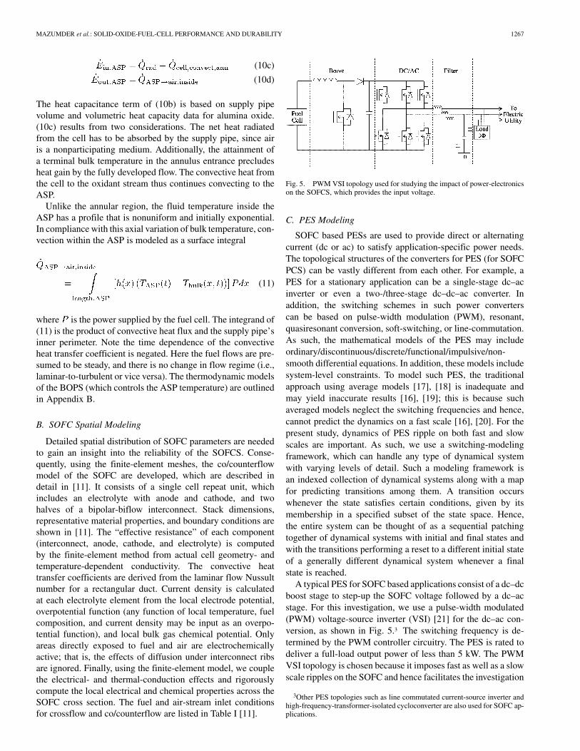
Fig. 5. PWM VSI topology used for studying the impact of power-electronicson the SOFCS, which provides the input voltage.
C. PES Modeling
SOFC based PESs are used to provide direct or alternatingcurrent (dc or ac) to satisfy application-specific power needs.The topological structures of the converters for PES (for SOFCPCS) can be vastly different from each other. For example, aPES for a stationary application can be a single-stage dc–acinverter or even a two-/three-stage dc–dc–ac converter. Inaddition, the switching schemes in such power converterscan be based on pulse-width modulation (PWM), resonant,quasiresonant conversion, soft-switching, or line-commutation.As such, the mathematical models of the PES may includeordinary/discontinuous/discrete/functional/impulsive/non-smooth differential equations. In addition, these models includesystem-level constraints. To model such PES, the traditionalapproach using average models [17], [18] is inadequate andmay yield inaccurate results [16], [19]; this is because suchaveraged models neglect the switching frequencies and hence,cannot predict the dynamics on a fast scale [16], [20]. For thepresent study, dynamics of PES ripple on both fast and slowscales are important. As such, we use a switching-modelingframework, which can handle any type of dynamical systemwith varying levels of detail. Such a modeling framework isan indexed collection of dynamical systems along with a mapfor predicting transitions among them. A transition occurswhenever the state satisfies certain conditions, given by itsmembership in a specified subset of the state space. Hence,the entire system can be thought of as a sequential patchingtogether of dynamical systems with initial and final states andwith the transitions performing a reset to a different initial stateof a generally different dynamical system whenever a finalstate is reached.
A typical PES for SOFC based applications consist of a dc–dcboost stage to step-up the SOFC voltage followed by a dc–acstage. For this investigation, we use a pulse-width modulated(PWM) voltage-source inverter (VSI) [21] for the dc–ac con-version, as shown in Fig. 5.3 The switching frequency is de-termined by the PWM controller circuitry. The PES is rated todeliver a full-load output power of less than 5 kW. The PWMVSI topology is chosen because it imposes fast as well as a slowscale ripples on the SOFC and hence facilitates the investigation
3Other PES topologies such as line commutated current-source inverter andhigh-frequency-transformer-isolated cycloconverter are also used for SOFC ap-plications.
1268 IEEE TRANSACTIONS ON POWER ELECTRONICS, VOL. 19, NO. 5, SEPTEMBER 2004
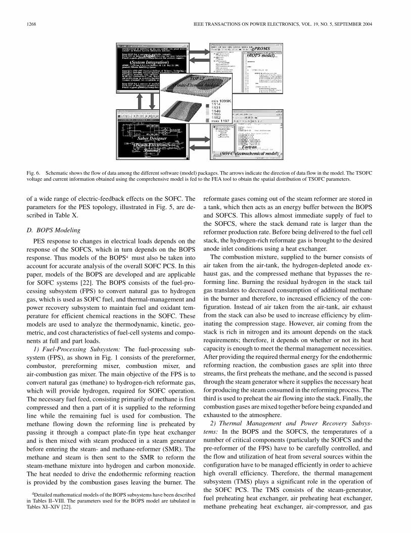
Fig. 6. Schematic shows the flow of data among the different software (model) packages. The arrows indicate the direction of data flow in the model. The TSOFCvoltage and current information obtained using the comprehensive model is fed to the FEA tool to obtain the spatial distribution of TSOFC parameters.
of a wide range of electric-feedback effects on the SOFC. Theparameters for the PES topology, illustrated in Fig. 5, are de-scribed in Table X.
D. BOPS Modeling
PES response to changes in electrical loads depends on theresponse of the SOFCS, which in turn depends on the BOPSresponse. Thus models of the BOPS4 must also be taken intoaccount for accurate analysis of the overall SOFC PCS. In thispaper, models of the BOPS are developed and are applicablefor SOFC systems [22]. The BOPS consists of the fuel-pro-cessing subsystem (FPS) to convert natural gas to hydrogengas, which is used as SOFC fuel, and thermal-management andpower recovery subsystem to maintain fuel and oxidant tem-perature for efficient chemical reactions in the SOFC. Thesemodels are used to analyze the thermodynamic, kinetic, geo-metric, and cost characteristics of fuel-cell systems and compo-nents at full and part loads.
1) Fuel-Processing Subsystem: The fuel-processing sub-system (FPS), as shown in Fig. 1 consists of the prereformer,combustor, prereforming mixer, combustion mixer, andair-combustion gas mixer. The main objective of the FPS is toconvert natural gas (methane) to hydrogen-rich reformate gas,which will provide hydrogen, required for SOFC operation.The necessary fuel feed, consisting primarily of methane is firstcompressed and then a part of it is supplied to the reformingline while the remaining fuel is used for combustion. Themethane flowing down the reforming line is preheated bypassing it through a compact plate-fin type heat exchangerand is then mixed with steam produced in a steam generatorbefore entering the steam- and methane-reformer (SMR). Themethane and steam is then sent to the SMR to reform thesteam-methane mixture into hydrogen and carbon monoxide.The heat needed to drive the endothermic reforming reactionis provided by the combustion gases leaving the burner. The
4Detailed mathematical models of the BOPS subsystems have been describedin Tables II–VIII. The parameters used for the BOPS model are tabulated inTables XI–XIV [22].
reformate gases coming out of the steam reformer are stored ina tank, which then acts as an energy buffer between the BOPSand SOFCS. This allows almost immediate supply of fuel tothe SOFCS, where the stack demand rate is larger than thereformer production rate. Before being delivered to the fuel cellstack, the hydrogen-rich reformate gas is brought to the desiredanode inlet conditions using a heat exchanger.
The combustion mixture, supplied to the burner consists ofair taken from the air-tank, the hydrogen-depleted anode ex-haust gas, and the compressed methane that bypasses the re-forming line. Burning the residual hydrogen in the stack tailgas translates to decreased consumption of additional methanein the burner and therefore, to increased efficiency of the con-figuration. Instead of air taken from the air-tank, air exhaustfrom the stack can also be used to increase efficiency by elim-inating the compression stage. However, air coming from thestack is rich in nitrogen and its amount depends on the stackrequirements; therefore, it depends on whether or not its heatcapacity is enough to meet the thermal management necessities.After providing the required thermal energy for the endothermicreforming reaction, the combustion gases are split into threestreams, the first preheats the methane, and the second is passedthrough the steam generator where it supplies the necessary heatfor producing the steam consumed in the reforming process. Thethird is used to preheat the air flowing into the stack. Finally, thecombustion gases are mixed together before being expanded andexhausted to the atmosphere.
2) Thermal Management and Power Recovery Subsys-tems: In the BOPS and the SOFCS, the temperatures of anumber of critical components (particularly the SOFCS and thepre-reformer of the FPS) have to be carefully controlled, andthe flow and utilization of heat from several sources within theconfiguration have to be managed efficiently in order to achievehigh overall efficiency. Therefore, the thermal managementsubsystem (TMS) plays a significant role in the operation ofthe SOFC PCS. The TMS consists of the steam-generator,fuel preheating heat exchanger, air preheating heat exchanger,methane preheating heat exchanger, air-compressor, and gas
MAZUMDER et al.: SOLID-OXIDE-FUEL-CELL PERFORMANCE AND DURABILITY 1269
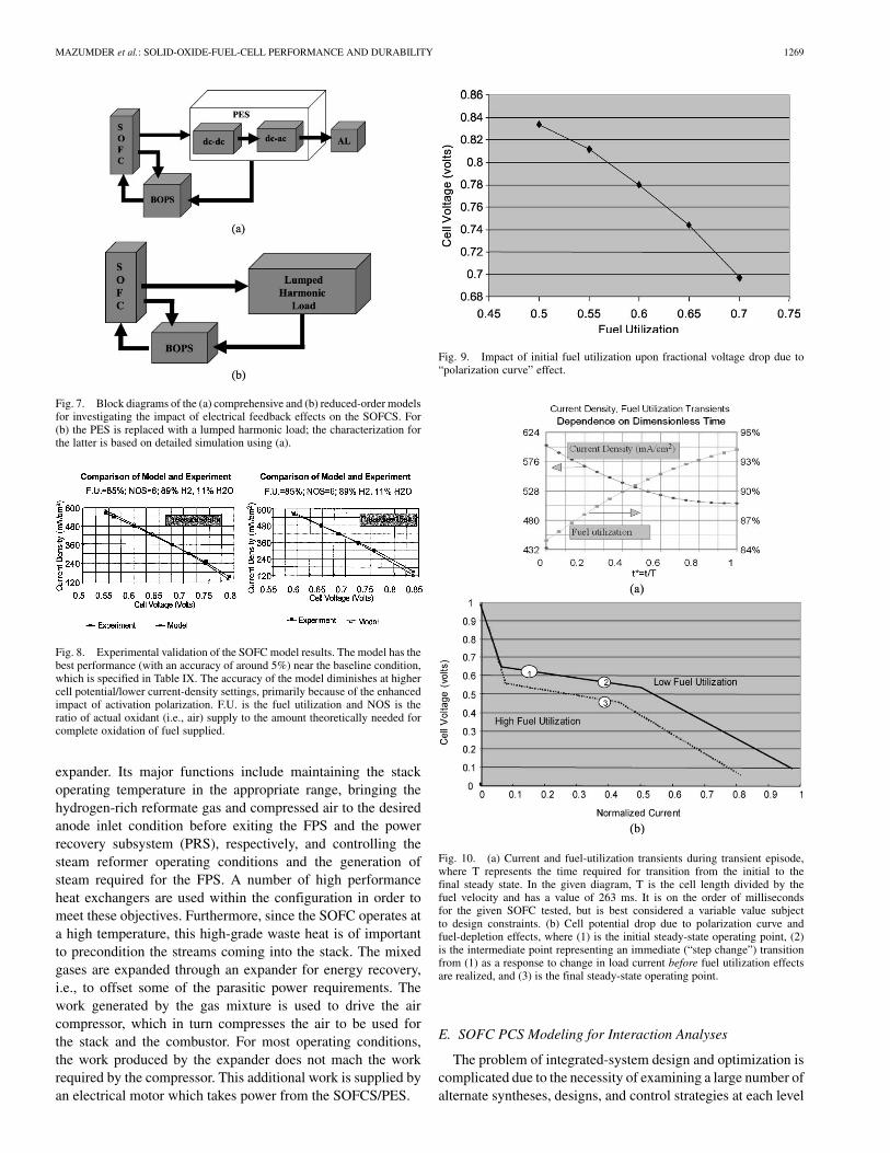
Fig. 7. Block diagrams of the (a) comprehensive and (b) reduced-order modelsfor investigating the impact of electrical feedback effects on the SOFCS. For(b) the PES is replaced with a lumped harmonic load; the characterization forthe latter is based on detailed simulation using (a).
Fig. 8. Experimental validation of the SOFC model results. The model has thebest performance (with an accuracy of around 5%) near the baseline condition,which is specified in Table IX. The accuracy of the model diminishes at highercell potential/lower current-density settings, primarily because of the enhancedimpact of activation polarization. F.U. is the fuel utilization and NOS is theratio of actual oxidant (i.e., air) supply to the amount theoretically needed forcomplete oxidation of fuel supplied.
expander. Its major functions include maintaining the stackoperating temperature in the appropriate range, bringing thehydrogen-rich reformate gas and compressed air to the desiredanode inlet condition before exiting the FPS and the powerrecovery subsystem (PRS), respectively, and controlling thesteam reformer operating conditions and the generation ofsteam required for the FPS. A number of high performanceheat exchangers are used within the configuration in order tomeet these objectives. Furthermore, since the SOFC operates ata high temperature, this high-grade waste heat is of importantto precondition the streams coming into the stack. The mixedgases are expanded through an expander for energy recovery,i.e., to offset some of the parasitic power requirements. Thework generated by the gas mixture is used to drive the aircompressor, which in turn compresses the air to be used forthe stack and the combustor. For most operating conditions,the work produced by the expander does not mach the workrequired by the compressor. This additional work is supplied byan electrical motor which takes power from the SOFCS/PES.
Fig. 9. Impact of initial fuel utilization upon fractional voltage drop due to“polarization curve” effect.
Fig. 10. (a) Current and fuel-utilization transients during transient episode,where T represents the time required for transition from the initial to thefinal steady state. In the given diagram, T is the cell length divided by thefuel velocity and has a value of 263 ms. It is on the order of millisecondsfor the given SOFC tested, but is best considered a variable value subjectto design constraints. (b) Cell potential drop due to polarization curve andfuel-depletion effects, where (1) is the initial steady-state operating point, (2)is the intermediate point representing an immediate (“step change”) transitionfrom (1) as a response to change in load current before fuel utilization effectsare realized, and (3) is the final steady-state operating point.
E. SOFC PCS Modeling for Interaction Analyses
The problem of integrated-system design and optimization iscomplicated due to the necessity of examining a large number ofalternate syntheses, designs, and control strategies at each level

1270 IEEE TRANSACTIONS ON POWER ELECTRONICS, VOL. 19, NO. 5, SEPTEMBER 2004
Fig. 11. (a) Hydrogen utilization and (b) air-supply-pipe temperature as afunction of the dc current and the ripple currents (expressed as a percentage ofthe dc current) drawn from the SOFCS. Here, I is the average magnitude of theSOFCS output current,�i is the variation of the steady-state current about thisaverage value, and the ripple factor is the ratio of �i over I .
of the problem. SOFCS responds quickly to changes in load,because of their rapid electrochemistry. The PES also respondsquickly to changes in AL or other variations. This is howevernot true for the thermal, mechanical, and chemical BOPScomponents and particularly for the fuel-processing subsystem,where load-following time constants are typically severalorders of magnitude higher. Difference in response times of theelectrochemical/electrical and thermal/mechanical/chemicalsubsystems of the overall SOFC PCS significantly increases thecomputational complexity. Hence, there is a need to developefficient simulation techniques to model such systems.
1) Comprehensive Integrated Model Using a MultisoftwarePlatform: The PES models are implemented using SaberDe-signer5 (developed by Synopsys, Inc.), while the SOFCSmodel is developed using Visual FORTRAN. Using the ex-isting database on BOPS models and powerful decompositiontechniques [22] for the integrated optimization of system andcomponent synthesis/design and operation, the BOPS model is
5Currently, among the commercially available simulators, SaberDesignerhas the most extensive library of mathematical computer models in power-elec-tronics components and systems, electromechanical-energy conversion,hydraulics, thermal, magnetic, control systems, and signal processing. Sab-erDesigner has its own programming language (MAST) for modeling but canaccept codes written in C and Fortran as well.
Fig. 12. (a) Hydrogen utilization and (b) air-supply-pipe temperature as afunction of the dc current and the frequency of the ripple current drawn fromthe SOFCS. Here, I is the average magnitude of the SOFCS output current,�i is the variation of the steady-state current about this average value, and theripple factor is the ratio of �i over I .
implemented using gPROMS6 (developed by Process SystemsEnterprise Limited). The PES and the SOFCS model are inte-grated on SaberDesigner simulator using dynamic link libraries(dlls). A comprehensive integrated model is developed toenable the use of software/package that is most suited to modelany given subsystem. Fig. 6 illustrates the data flow among thevarious software packages of the comprehensive model, and themultisoftware simulation platform using iSIGHT7 (developedby Engineous software) [13], [14], respectively.
Such a tool enables dynamic simulation and modeling ofthe SOFC PCS. The transient and steady-state results thusobtained are fed to a FEA tool (TOPAZ) for spatial analysesof the effects of electrical feedbacks on the performance anddurability of the SOFC. With these tools for dynamic simulationand modeling, it is possible to conduct parametric studies andoptimizations for SOFC PCS subsystem interaction analysesand to determine control strategies (for stationary and/or trans-portation auxiliary power load profiles) and investigate theireffects on the efficiency, power density, fuel utilization and
6The kernel of gPROMS is written in C and, hence, the BOPS models devel-oped in this environment will seamlessly integrate with SaberDesigner.
7iSIGHT integrates simulation codes and provides an interface between Sab-erDesigner and gPROMS [13], [14].

MAZUMDER et al.: SOLID-OXIDE-FUEL-CELL PERFORMANCE AND DURABILITY 1271
Fig. 13. (a) Load/current transient, which result in drop in SOFC output voltage, (b) and (c) spatial variation of current density and hydrogen utilization acrossthe SOFC cross section using FEA after the load transient, and (d) mean variation of temperature at the extreme ends of the SOFC for a load transient.
Fig. 14. Maximum allocable heat and current for a microcrack density of 30%as a function of fracture toughness.
conversion, system response and configuration, and componentdesign of SOFC systems.
2) Reduced-Order Models to Resolve the Effect of MultipleTime Scales: Significant differences in the response times ofthe electrochemical/electrical and thermal/mechanical/chem-ical subsystems of the SOFC PCS imply that simulations usingthe comprehensive model are extremely time consuming ona personal computer/SUN workstation. Hence, more efficientsimulation techniques are needed for studying system interac-tions. Because a PES model comprises a number of switchingfunctions, its real-time simulation using the comprehensive
Fig. 15. Behavior SOFC output current during a load transient at time =
0:18 s. Control of the inverter using SVM (as compared to SPWM) leads tofaster recovery of SOFC output current. However, this may not always be usefulas demonstrated in Fig. 24.
model, outlined in the previous section, is extremely tedious. Toreduce the complexity of the simulation, a two-step approach istaken. In the first step, simulations on different PES topologiesare performed with an ideal voltage source as the input andthe harmonic content of the PES input current is estimated. Inthe second step, the PES is replaced by a lumped load (withthe harmonic content as estimated in the first step) in thereduced-order simulation platform as illustrated in Fig. 7(a)and (b). While developing the lumped load, it is ensured thatall the harmonics are present and the magnitudes matched, sothat the stresses imposed by the lumped load on the SOFC are

1272 IEEE TRANSACTIONS ON POWER ELECTRONICS, VOL. 19, NO. 5, SEPTEMBER 2004
similar to those imposed by the PES. Next, the reduced ordermodel is used to investigate the effect of the PES dynamicson the SOFCS life and performance. This model reduces thecomputational time for the simulation without sacrificing theperformance.
3) Methodology to Investigate the SOFC-PES Interac-tions: Hydrogen utilization and thermal cycling of SOFCSmaterial have a major impact on its reliability. Hydrogenutilization, [11] is obtained from current drawn by the PESusing the expression
(12)
where is the SOFCS output current, is the hydrogen flowrate which is determined by the BOPS, and determines thecharge flow between the anode and the cathode.
The heat dissipation in the SOFC is due to
a) heat dissipated in the effective resistance of the fuel cell;b) heat dissipation due to the chemical reaction .
It has been reported [6] that, heat dissipated by the fuel cell, ifnot managed properly, can have a significant impact on the mi-crocrack density of the fuel cell. For a given material and spa-tial heat source, the microcrack density is directly proportionalto the heat rate and increases beyond a certain threshold heatingrate given by
(13)
where is the length parameter that characterizes spatialnonuniformity of heat source, J s m K is thethermal diffusivity, K is the coefficientof linear thermal expansion, is the fracturetoughness of the material, is Young’s elastic modulusof uncracked material, is the crack size, and isPoisson’s ratio of the uncracked material.
The threshold current beyond which the microcrack densityincreases (for a particular fracture toughness of the SOFC elec-trolyte) is given by
(14)
where is the area-specific resistance of the SOFC andis the heating rate due to the chemical reaction of the
SOFC.SOFC temperature is obtained using basic thermodynamic
equations and is outlined in [10]. These results are used to relatethe SOFC output current to the stack temperature. Theoreticalstudies indicate interaction between the standard cathode,
(LSM) and the standard electrolyte(YSZ) above temperatures of 1000 C [3]. In long-term oper-ation, an interlayer of forms, whose conductivity is
Fig. 16. (a) Hydrogen utilization and (b) current density across the crosssection of the SOFC during a load-transient. It is obvious, that the betterperformance of SVM comes at the price of higher SOFC current density andhigher fuel utilization. It is, therefore, important to recognize that modulationstrategies such as SVM achieve superior performances for PES converter fedby a “stiff” dc voltage source, may require additional provisions for energybuffering devices to attain the same benefit. Such provisions may include,high-pressure fuel-storage tank in the BOPS, lower levels of initial fuelutilization, or alternate electrical-energy source just for the transient conditions.
TABLE IINPUT OPERATING CONDITIONS OF FINITE-ELEMENT MODEL
much less than that of LSM and hence has an impact on theoutput voltage and current supplied by the SOFC.

MAZUMDER et al.: SOLID-OXIDE-FUEL-CELL PERFORMANCE AND DURABILITY 1273
TABLE IIGENERALIZED MODEL OF FUEL-PROCESSING SUBSYSTEM
III. RESULTS
Table IX outlines the SOFC baseline conditions for analysis.We begin, with the responses of the SOFC under unslavedcondition. The validation of the SOFC-stack model withinan impressive accuracy of 3 to 5% (across a domain ofpressure ratios) is shown in Fig. 8. The model transitions fromsmall over predictions of current to slight under predictionsas operating voltage increases; this is attributable to error incalculating polarization. For the same SOFC model, Fig. 9shows the impact of variations in fuel utilization on the celloutput voltage due to polarization-curve effect. The larger theinitial fuel utilization, the more prevalent the reactant depletioneffects that manifest via lowered Nernst potentials and limitingcurrent densities [as shown in Fig. 10(a) and (b)]; hence, the“reactant depletion/accumulation” effect of hikes in current issubstantially more influential. Fig. 10(a), illustrates the trendsin current density and fuel utilization caused by an idealizedstep decrease in cell potential. Fig. 10(b), shows decreases incell potential, as a result of progressive reactant depletion toattain a higher demand in current.
Figs. 11 and 12,8 illustrate the variations in the hydrogenutilization and the air-supply-pipe-temperature with the ripple,amplitude, and frequency of the current drawn by the PESfrom the SOFCS. It is clear from Fig. 11(a) that, to meethigher load-demands, the hydrogen utilization has to increase
8So far, we have focused at the cell level and on unslaved operationof the SOFC. For power delivery to the ALs, several of these cells areconnected to form a SOFCS and then interfaced to the PCS. To resolvethe electrical-feedback effects, the lumped harmonic model (Fig. 8), whichreplaces the PES and the AL, needs to account for low-harmonic as wellas switching ripple frequencies.
TABLE IIIKINETIC MODEL OF THE SMR REACTOR
significantly. Fig. 11(b), illustrates the variation of the ASPtemperature with variation in the load. Magnitude of the currentripple has a minimal impact at low loads. However at higherloads, an increase in current leads to an increase in the hydrogenutilization. However, the variation of the ASP temperature withcurrent ripple is insignificant. Fig. 12(a) and (b) illustrates thevariation of the hydrogen utilization and the ASP temperatureof the SOFCS as a function of the dc current and the frequencyof the ripple current drawn from the SOFCS.
The focus of Figs. 11 and 12 has been on electrical feed-backs during the steady state of the SOFC PCS. Another pos-sibility of electrical perturbation is due to a sudden change inthe magnitude of the AL. Fig. 13, illustrates the impact of suchload-transients on SOFC temperature distribution. Fig. 13(a)shows, that with the increase in the output current of the SOFC,its output voltage decreases. This is accompanied by an increasein the temperature as shown in Fig. 13(d) on a large time frame.This plot is helpful in ascertaining the mean or the envelopeof the temperature distribution; however, it cannot predict thespatial distribution (of the temperature), which requires spa-tial modeling using finite-element analysis. Fig. 13(b) and (c),reveal the spatial distribution of current density and hydrogenutilization across the SOFC cross section after the load tran-sient. Clearly, the detailed spatial analyses reveals that the dis-tribution of SOFC material properties is nonuniform and somesections may be more susceptible to failure than others undersimilar repetitive load transients [23], [24].
Increase in the ASP temperature and the accompanying heatgeneration have a degrading effect on the SOFC material prop-erties. Basic thermoelectric equations governing SOFC materialproperties are discussed in [13] and a preliminary result showinga direct correlation between the current and the fracture tough-ness is established. Fig. 14, shows the variation of the maximumallocable heat and the maximum steady-state current that a fuelcell can handle for a 30% microcrack density [calculated using(13) and (14)]. Beyond these threshold values, high microcrackdensities are expected which would significantly degrade the re-liability of the SOFC.
An obvious question that arises out of these analysesis whether suitable choice of PES control and modulationstrategies can mitigate the impact of electrical perturbation
1274 IEEE TRANSACTIONS ON POWER ELECTRONICS, VOL. 19, NO. 5, SEPTEMBER 2004
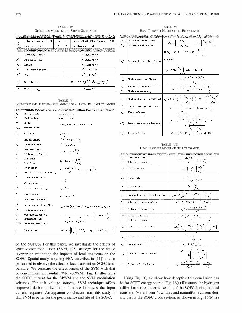
TABLE IVGEOMETRIC MODEL OF THE STEAM GENERATOR
TABLE VGEOMETRIC AND HEAT TRANSFER MODELS OF A PLATE-FIN HEAT EXCHANGER
on the SOFCS? For this paper, we investigate the effects ofspace-vector modulation (SVM) [25] strategy for the dc–acinverter on mitigating the impacts of load transients on theSOFC. Spatial analysis (using FEA described in [11]) is alsoperformed to observe the effect of load transient on SOFC tem-perature. We compare the effectiveness of the SVM with thatof conventional sinusoidal PWM (SPWM). Fig. 15 illustratesthe SOFC current for the SPWM and the SVM modulationschemes. For stiff voltage sources, SVM technique offersimproved dc-bus utilization and hence improves the inputcurrent response. An apparent conclusion from this study isthat SVM is better for the performance and life of the SOFC.
TABLE VIHEAT TRANSFER MODEL OF THE ECONOMIZER
TABLE VIIHEAT TRANSFER MODEL OF THE EVAPORATOR
Using Fig. 16, we show how deceptive this conclusion canbe for SOFC energy source. Fig. 16(a) illustrates the hydrogenutilization across the cross section of the SOFC during the loadtransient. Nonuniform flow rates and nonuniform current den-sity across the SOFC cross section, as shown in Fig. 16(b) are
MAZUMDER et al.: SOLID-OXIDE-FUEL-CELL PERFORMANCE AND DURABILITY 1275
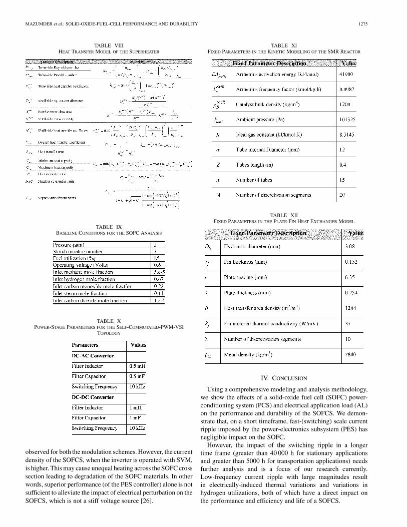
TABLE VIIIHEAT TRANSFER MODEL OF THE SUPERHEATER
TABLE IXBASELINE CONDITIONS FOR THE SOFC ANALYSIS
TABLE XPOWER-STAGE PARAMETERS FOR THE SELF-COMMUTATED-PWM-VSI
TOPOLOGY
observed for both the modulation schemes. However, the currentdensity of the SOFCS, when the inverter is operated with SVM,is higher. This may cause unequal heating across the SOFC crosssection leading to degradation of the SOFC materials. In otherwords, superior performance (of the PES controller) alone is notsufficient to alleviate the impact of electrical perturbation on theSOFCS, which is not a stiff voltage source [26].
TABLE XIFIXED PARAMETERS IN THE KINETIC MODELING OF THE SMR REACTOR
TABLE XIIFIXED PARAMETERS IN THE PLATE-FIN HEAT EXCHANGER MODEL
IV. CONCLUSION
Using a comprehensive modeling and analysis methodology,we show the effects of a solid-oxide fuel cell (SOFC) power-conditioning system (PCS) and electrical application load (AL)on the performance and durability of the SOFCS. We demon-strate that, on a short timeframe, fast-(switching) scale currentripple imposed by the power-electronics subsystem (PES) hasnegligible impact on the SOFC.
However, the impact of the switching ripple in a longertime frame (greater than 40 000 h for stationary applicationsand greater than 5000 h for transportation applications) needsfurther analysis and is a focus of our research currently.Low-frequency current ripple with large magnitudes resultin electrically-induced thermal variations and variations inhydrogen utilizations, both of which have a direct impact onthe performance and efficiency and life of a SOFCS.

1276 IEEE TRANSACTIONS ON POWER ELECTRONICS, VOL. 19, NO. 5, SEPTEMBER 2004
TABLE XIIIFIXED PARAMETERS IN THE STEAM GENERATOR MODEL
TABLE XIVFIXED PARAMETERS IN THE COMPRESSOR AND EXPANDER MODELS
Load transients, depending on severity, have a significant im-pact and lead to nonuniform thermal distribution. Depending onhow high the temperature is at any spatial location within thestack/cell, it can have a negative impact on the material prop-erties and microcrack densities of the SOFC and hence, on thedurability of the SOFC.
We also demonstrate that, space-vector modulation (SVM),as compared to sine-wave pulse width modulation (SPWM),of the inverter, yields faster dynamic response under load-tran-sients. While the superior dynamic-performance capability ofSVM for three-phase inverters is well known, what is often over-looked in such analysis is the need for a stiff dc voltage source.As such, for SOFC, which is not a stiff dc voltage source, theenhanced performance of SVM comes at the cost of higher lo-calized current densities and fuel-flow rates, both of which maybe detrimental to the SOFCS. Nonuniformities during load tran-sients will result in localized oxidization of SOFC electrolytematerial, which could result in reduced conductivity because ofthe formation of .
APPENDIX A
See Table I.
APPENDIX B
See Tables II–VIII.
APPENDIX C
See Tables IX–XIV.
REFERENCES
[1] A. V. Virkar, J. W. Kim, K. Mehta, and K. Z. Fung. (1997) Low Temper-ature, high performance, planar solid oxide fuel cells and stacks. [On-line]www.netl.doe.gov/publications/proceedings/97/97fc/FC6-5.PDF
[2] X. Huang and K. Reifsnider, “Modeling long-term performance of solidoxide fuel cells: a phenomenological approach,” in Proc. 15th Annu.Conf. Fossil Energy Materials, Knoxville, TN, Apr./May 2001.
[3] Y. C. Hsiao and J. R. Selman, “The degradation of SOFC electrodes,” inProc. Solid State Ionics, vol. 98, June 1997, pp. 33–38.
[4] R. P. Travis, “Mechanical integrity issues of fuel cells,” in Proc. ASME1st Int. Conf. Fuel Cell Science, Engineering and Technology, Mar.2003, pp. 89–94.
[5] A. C. Burt, I. B. Celik, R. S. Gemmen, and A. V. Smirnov, “Influenceof radiative heat transfer on variation of cell voltage within a stack,”in Proc. ASME 1st Int. Conf. Fuel Cell Science, Engineering and Tech-nology, Mar. 2003, pp. 217–223.
[6] J. Qu, A. Fedorov, and C. Haynes. (2003, Aug.) An integrated approachto modeling and mitigating SOFC Failure. Tech. Rep., Nat. EnergyTechnol. Lab. [Online]http://www.netl.doe.gov/scng/projects/end-se/fuelcells/seca/pubs/seca41571Monthly%20Reports%20Au-gust%202 003.pdf
[7] E. Achenbach, “Response of a solid oxide fuel cell to load change,” J.Power Sources, vol. 57, pp. 105–109, 1995.
[8] J. Hartvigsen, S. Elangovan, and A. Khandkar, “Selection of SOFC stackoperating point for optimal balance of efficiency and power,” in Proc.3rd Eur. Solid-Oxide Fuel Cell Forum, 1998, pp. 517–524.
[9] C. Haynes, “Simulation of tubular solid oxide fuel cell behavior forintegration into gas turbine cycles,” Ph.D. dissertation, Georgia Inst.Technol., Atlanta, 1999.
[10] C. L. Haynes and W. J. Wepfer, “Design for power of a commercial-grade tubular solid oxide fuel cell,” J. Energy Conv. Manag., vol. 41, pp.1123–1139, 2000.
[11] J. Hartvigsen, “A transient model of solid-oxide fuel cell operation ina high cycle regime of inverter induced current variation,” in Proc. 8thInt. Fatigue Conf., vol. 4, Stockholm, Sweden, 2002, pp. 2187–2196.
[12] R. Gemmen, “Analysis for the effect of inverter ripple current on fuelcell operating condition,” J. Fluids Eng., vol. 125, no. 3, pp. 576–585,2003.
[13] S. K. Mazumder, R. K. Burra, K. Acharya, M. R. von Spakovsky, D.J. Nelson, D. Rancruel, C. Haynes, and R. Williams, “Development ofa comprehensive simulation platform to investigate system interactionsamong solid-oxide fuel cell, power-conditioning systems, and applica-tion loads,” in Proc. ASME 1st Int. Conf. Fuel Cell Sci., Eng. Technol.,Mar. 2003, pp. 101–110.
[14] K. Acharya, S. K. Mazumder, R. K. Burra, R. Williams, and C.Haynes, “System-interaction analyses of solid-oxide fuel cell (SOFC)power-conditioning system,” in Proc. IEEE Industry ApplicationsSociety Conf., 2003, pp. 2026–2032.
[15] K. Acharya, S. K. Mazumder, and R. K. Burra, “Solid-oxide fuel cellpower-conditioning systems interaction analysis: resolution of the elec-trical-feedback effects on SOFC performance and durability,” in Proc.IEEE Applied Power Electronics Conf., 2004.

MAZUMDER et al.: SOLID-OXIDE-FUEL-CELL PERFORMANCE AND DURABILITY 1277
[16] S. K. Mazumder, A. H. Nayfeh, and D. Boroyevich, “Theoretical andexperimental investigation of the fast- and slow-scale instabilities of adc–dc converter,” IEEE Trans. Power Electron., vol. 16, pp. 201–216,Mar. 2001.
[17] R. D. Middlebrook and S. Cuk, “A general unified approach to modelingswitching-converter power stages,” in Proc. IEEE Power ElectronicsSpecialists Conf., 1977, pp. 521–550.
[18] , “A general unified approach to modeling switching dc to dc con-verters in discontinuous conduction mode,” in Proc. IEEE Power Elec-tronic Specialists Conf., 1977, pp. 36–57.
[19] F. C. Lee, Modeling, Analysis, and Design of PWM Con-verter. Blacksburg, VA: Virginia Power Electronic Center, 1990.
[20] S. K. Mazumder, A. H. Nayfeh, and D. Boroyevich, “Nonlinear dy-namics and stability analysis of parallel dc–dc converters including theeffect of saturation,” JVC: Nonlinear Dyn. Contr., vol. 9, pp. 775–789,2001.
[21] Y. Konishi, Y. L. Feng, and M. Nakaoka, “Three-phase voltage-fed in-verter with new conceptual optimum PWM strategy for high-power ap-plications,” in Proc. Power Electronics and Variable Speed Drives Conf.,1998, pp. 600–605.
[22] N. Georgopoulos, M. R. von Spakovsky, and J. R. Munoz, “Applicationof a decomposition strategy to the optimal synthesis/design and opera-tion of a fuel cell based total energy system for residential applications,”in Proc. Int. Mechanical Engineering Congr. Expo. (IMECE’02), NewYork, NY, 2002.
[23] S. K. Mazumder, M. R. von Spakovsky, C. Haynes, K. Acharya, R.Burra, D. Rancruel, R. Williams, and D. Nelson, “An Investigation toResolve the Interaction Between Fuel Cell, Power Conditioning Systemand Application Loads,” Phase-I Topical Rep., U.S. DoE, CooperativeAgreement DE-FC26-02NT41574, Oct. 2002.
[24] S. K. Mazumder, “Nonlinear analysis and control of standalone, par-allel dc–dc, and parallel multiphase PWM converters,” Ph.D. disserta-tion, Virginia Polytech. Inst. State Univ., Blacksburg, 2001.
[25] J. Holtz, W. Lotzkat, and A. M. Khambadkone, “On continuous controlof PWM inverters in the overmodulation range including the six-stepmode,” IEEE Trans. Power Electron., vol. PE-8, pp. 546–553, Oct. 1993.
[26] S. K. Mazumder, A. H. Nayfeh, and D. Boroyevich, “Robust controlof parallel dc–dc buck converters by combing the concepts of integral-variable-structure- and multiple-sliding-surface control schemes,” IEEETrans. Power Electron., vol. 17, pp. 428–437, May 2002.
Sudip K. Mazumder (SM’03) received the Ph.D. de-gree in electrical and computer engineering from theVirginia Polytechnic Institute and State University,Blacksburg, in 2001.
Currently, he is an Assistant Professor at theDepartment of Electrical and Computer Engi-neering, University of Illinois, Chicago. He is alsothe Director of the Laboratory for Energy andSwitching-Electronics Systems. He has over 10years of professional experience and has held R&Dand design positions in leading industrial organi-
zations. In Summer 2004, he was a Faculty Fellow at the Pacific NorthwestNational Laboratory (PNNL). He has published 40 refereed and invited journaland conference papers and is a Reviewer for six international journals. Hisareas of expertise and current interests include stability analysis of interactivepower-electronic networks (IPNs) and wireless control of IPNs, fuel-cell basedpower-electronics systems, and analysis of the electrical-feedback effects ofpower electronics on fuel cell, optically-switched power conversion, self-pow-ered wireless sensors, advanced control and DSP/RISC and ASIC-basedembedded controllers for power supplies/systems and motor drives, and soft-and hard-switching topologies and techniques in power converters.
Dr. Mazumder received the NSF CAREER and the DOE SECA awardsin 2003 and 2002, respectively, and the Prize-Paper Award from the IEEETRANSACTIONS ON POWER ELECTRONICS and the IEEE POWER ELECTRONICS
LETTERS in 2002. He is an Associate Editor for the IEEE TRANSACTIONS ON
INDUSTRIAL ELECTRONICS and IEEE POWER ELECTRONICS LETTERS, and islisted in Who’s Who in Engineering Education.
Kaustuva Acharya (S’01) received the B.E. degreein electronics and communication engineering fromRegional Engineering College, Bhopal, India, in2000 and the M.S. degree in electrical engineeringfrom the University of Illinois, Chicago, in 2003where he is currently pursuing the Ph.D. degree inelectrical engineering.
He is a Research Assistant at the Laboratoryfor Energy and Switching-Electronics Systems,University of Illinois. His research interests includedistributed generation, and modeling, analyses, and
control of interactive power networks for distributed power systems.
Comas Lamar Haynes received the B.S. degreein mechanical engineering from the Florida Agri-cultural and Mechanical University, Tallahassee,in 1994 and the Ph.D. degree from the WoodruffSchool of Mechanical Engineering, Georgia Instituteof Technology (Georgia Tech), Atlanta, in 1999.
While pursuing the Ph.D. degree, he was a Grad-uate Research Assistant and served as a Coinstructorof thermal science courses. He then became anEngineering Researcher and Program Coordinatorfor Facilitating Academic Careers in Engineering
and Science (FACES). This program, which is a collaborative effort betweenGeorgia Tech, Morehouse College, and Spelman College, is designed toincrease the number of African-American doctoral candidates in scienceand engineering. After a two-year tenure in this capacity, he became andpresently is a faculty member at the Georgia Tech Center for InnovativeFuel Cell and Battery Technologies. His research includes modeling steadystate and dynamic fuel cell behavior, thermal management of fuel cells,second law analyses of fuel cells, and the thermodynamic optimization ofhybrid fuel cell/heat engine cycles. Example investigations include using heatexchanger analogies in advanced fuel cells designs, cost-effective thermalmanagement of low and high temperature fuel cells via optimal electroac-tive area allocation, and fuel cells system integration and optimization foradvanced vehicles. He also develops fuel cells systems curricula for publicand college courses and experimental laboratories.
Dr. Haynes received a NASA Scholarship from the Florida Agricultural andMechanical University and the prestigious National Science Foundation Grad-uate School Fellowship.
Robert Williams, Jr. received the B.S. degree (withhonors) in chemical engineering from the FloridaAgricultural and Mechanical University, Tallahassee,in 2001 and the M.S. degree in materials scienceand engineering from the Georgia Institute ofTechnology, Atlanta, in 2003, where he is currentlypursuing the Ph.D. degree.
His research includes modeling steady-state andtransient fuel cell behavior as well as reaction kineticsand formulation of oxygen reduction mechanisms onmixed ionic electronic conductors (MIEC).
Mr. Williams received a NASA Scholarship from the Florida Agriculturaland Mechanical University, the GEM Consortium Graduate Fellowship, the Na-tional Science Foundation (NSF) Graduate Research Fellowship, the GeorgiaTech Presidential Fellowship, and the Facilitating Academic Careers in Engi-neering and Science (FACES).

1278 IEEE TRANSACTIONS ON POWER ELECTRONICS, VOL. 19, NO. 5, SEPTEMBER 2004
Michael R. von Spakovsky received the B.S. degreein aerospace engineering from Auburn University,Auburn, AL, in 1974 and the M.S and Ph.D.degrees in mechanical engineering from the GeorgiaInstitute of Technology, Atlanta, in 1980 and 1986,respectively.
He has over 17 years of teaching and research ex-perience in academia and over 17 years of industryexperience in mechanical engineering, power utilitysystems, aerospace engineering, and software engi-neering. While at Auburn, he worked for three and
a half years at NASA, Huntsville, AL, and from 1974 to 1984 and from 1987to 1989 worked in the power utility industry first as an Engineer and then asa Consultant. From 1989 to 1996, he was an Educator and Researcher at theSwiss Federal Institute of Technology, Lausanne, Switzerland, where he leada research team in the modeling and systems integration of complex energysystems and taught classes in the thermodynamics of indirect and direct en-ergy conversion systems (including fuel cells). In January 1997, he joined theMechanical Engineering faculty at the Virginia Polytechnic Institute and StateUniversity, Blacksburg, as Professor and Director of the Energy ManagementInstitute (now the Center for Energy Systems Research). He currently teachesundergraduate and graduate courses in thermodynamics, industrial energy sys-tems, fuel cell systems, and energy system design. He has published widelyin scholarly journals, conference proceedings, etc. (over 115 publications) andhas given talks, seminar and short courses (e.g., on fuel cells) worldwide. He isAssociate Editor of the International Journal of Fuel Cell Science and Tech-nology and Editor-in-Chief of the International Journal of Thermodyanmics(formerly the International Journal of Applied Thermodyanmics). His researchinterests include computational methods for modeling and optimizing complexenergy systems, methodological approaches for the integrated synthesis, design,operation and diagnosis of such systems (stationary power as well as, for ex-ample, high performance aircraft systems), theoretical irreversible and equilib-rium thermodynamics with a focus on the unified quantum theory of mechanicsand thermodynamics, and fuel cell applications for both transportation and dis-tributed power generation.
Dr. von Spakovsky is a member of the AIAA, Sigma Xi, Tau Beta Pi, anda Fellow of the ASME. He is also ASME representative to the U.S. CADDETNational Team and a member of the Executive Committee, Advanced EnergySystems Division, ASME.
Douglas J. Nelson received the B.S. and M.S. de-grees in mechanical engineering from Virginia Poly-technic Institute and State University (Virginia Tech),Blacksburg, in 1978 and 1979, respectively, and thePh.D. degree in mechanical engineering from Ari-zona State University, Tempe, in 1986.
He worked for two years as a Systems Engineerfor Exxon Corporation. He is currently Professor ofMechanical Engineering at Virginia Tech. He teachesundergraduate and graduate courses in fuel cell sys-tems, advanced technology vehicles, and design. He
is the Director of the Department of Energy GATE Center for Automotive FuelCell Systems, and the Faculty Advisor for the Hybrid Electric Vehicle Team(HEVT), Virginia Tech.
Dr. Nelson received the Ralph R. Teetor Educational Award from SAEInternational in 1996 and the NSF FutureCar Faculty Advisor’s Award in1998. He is a member of SAE and ASME. He is a member of the InternationalTechnical Committee for the Challenge Bibendum sustainable mobility eventfor advanced technology vehicles. He is a registered Professional Engineerin the state of Arizona.
Diego F. Rancruel received the B.S degree (withhonors) in mechanical engineering and the M.S.degree in materials engineering from the Universidaddel Valle, Colombia, in 1995 and 1997, respectively,the M.S. degree in business administration fromICESI University, Colombia, in 1999, and theM.S. degree in mechanical engineering from theVirginia Polytechnic Institute and State University,Blacksburg, in 2003, where he is currently pursuingthe Ph.D. degree.
He has five years of industry experience as a SteamGeneration Instructor, Metrology Chief Engineer, Maintenance Manager, andEngineering Project Manager.
Joseph Hartvigsen received the B.S. degree fromBrigham Young University, Provo, UT, in 1982and the M.S. degree from Iowa State University,Ames, in 1985, both in chemical engineering. HisM.S. research, which produced a new process forsilicon nitride synthesis, was performed at the AmesLaboratory, Department of Energy.
His earlier industrial experience was in thedefense aerospace field, with Hercules Aerospaceand the Boeing Defense and Space Group. Hisresponsibilities there included thermal, fluids,
thermodynamic and mass transfer analysis of solid rocket propulsion, thermalprotection systems for hypersonic aircraft, research on aircraft visual/IR signa-ture reduction, splashdown analysis of manned space vehicles, and analysis ofmanufacturing processes for advanced materials. In 1991, he joined Ceramatec,Salt Lake City, UT, and began development of a detailed SOFC stack model.His work in SOFC system engineering has led to more than ten patents relatedto SOFC systems, fuel processing, interconnect, and cell designs. His analysisof the thermodynamics of natural gas reformation guided the design anddemonstration of an integrated 1.5-kW planar solid oxide fuel cell system withan integrated natural gas reformer and recuperative heat exchanger.
Mr. Hartvigsen received the NASA SBIR Award for a solid electrolyte hy-drogen and syngas production process.
Randy S. Gemmen received the M.S. degree inaerospace engineering and the Ph.D. degree inmechanical engineering and applied mechanics fromthe University of Michigan, Ann Arbor.
He has been with the Department of Energy (DoE)for about 12 years. During this time, he has performedresearch in combustion testing for gas turbine powersystems, fuel cell testing and evaluation, and hybrid(fuel cell + gas turbine) systems dynamic analysis.He is currently the Team Leader for Fuel Cell Re-search in the Gas Energy Systems Division, Office of
Science and Technology. His present work is focused on the development of val-idation and material property data for detailed models that are being advancedat NETL. He has several patents, and has published over 23 journal and confer-ence papers.