ieee transactions on pattern analysis and...
TRANSCRIPT

Bidirectional Texture Function Modeling:A State of the Art Survey
Ji�rı Filip, Member, IEEE, and Michal Haindl, Senior Member, IEEE
Abstract—An ever-growing number of real-world computer vision applications require classification, segmentation, retrieval, or
realistic rendering of genuine materials. However, the appearance of real materials dramatically changes with illumination and viewing
variations. Thus, the only reliable representation of material visual properties requires capturing of its reflectance in as wide range of
light and camera position combinations as possible. This is a principle of the recent most advanced texture representation, the
Bidirectional Texture Function (BTF). Multispectral BTF is a seven-dimensional function that depends on view and illumination
directions as well as on planar texture coordinates. BTF is typically obtained by measurement of thousands of images covering many
combinations of illumination and viewing angles. However, the large size of such measurements has prohibited their practical
exploitation in any sensible application until recently. During the last few years, the first BTF measurement, compression, modeling,
and rendering methods have emerged. In this paper, we categorize, critically survey, and psychophysically compare such approaches,
which were published in this newly arising and important computer vision and graphics area.
Index Terms—BTF, BRDF, 3D texture, surface texture, texture measurement, texture analysis, texture synthesis, texture modeling,
data compression, psychophysical study, light transport.
Ç
1 INTRODUCTION
ROBUST visual classification, segmentation, retrieval, orview/illumination invariant methods dealing with
images of textured natural materials, as well as augmentedreality applications creating virtual objects in renderedscenes with real material surface optical properties, requirerealistic physically correct textures. Such texture represen-tation considerably depends on the view and illuminationdirections and can be efficiently and most accuratelyobtained in the form of rough surface textures representedby Bidirectional Texture Function. Additionally, applica-tions of this advanced texture representation allow accuratephoto-realistic material appearance approximation for suchcomplex tasks as visual safety simulations or interior designin automotive/airspace industry (Fig. 2), architecture, ordermatology [8] among others.
The first attempt to formally specify real materialreflectance was by Nicodemus et al. [76], who introduceda novel nomenclature for the Bidirectional ReflectanceDistribution Function (BRDF), although its importance haslong been recognized by artists and scientists such asGalileo [78]. A four-dimensional BRDF was formalized in[76] as a specific case of eight-dimensional BidirectionalScattering Surface Reflectance Distribution Function (BSSRDF),restricted to opaque materials. Multispectral BRDF is a5D function describing how a sample’s color reflectancedepending on illumination and viewing directions. Two
principal properties of BRDF are view and illuminationdirection reciprocity and energy conservation. To represent thespatial dependencies in surface texture, a BRDF can beextended to the six-dimensional Spatially Varying BRDF(SVBRDF), i.e., a set of surface points with mutuallyindependent BRDFs. However, the two mentioned proper-ties impose restrictions on SVBRDF use, mostly forrepresentation of near-flat and opaque materials.
Twenty years later, Dana et al. [10] proposed a moregeneral representation of sample structure geometry and itslight transport properties [54], in the form of BidirectionalTexture Function (BTF), which is applicable to most real-world surfaces. Multispectral BTF is a seven-dimensionalfunction, which considers measurement dependency oncolor spectrum, planar material position, as well as itsdependence on illumination and viewing angles:
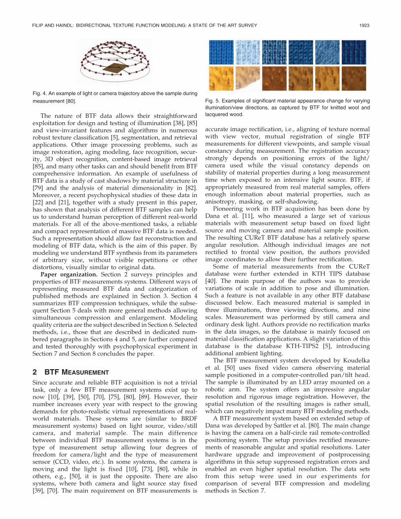
BTF ðr; �i; �i; �v; �vÞ; ð1Þwhere the multi-index r ¼ ½r1; r2; r3� specifies planar hor-izontal and vertical position in material sample image, r3 isthe spectral index, and �; � are elevation and azimuthalangles of the illumination and view direction vector (seeFig. 3). The BTF measurements comprise a whole hemi-sphere of light and camera positions in observed materialsample coordinates according to the selected quantizationsteps (see Fig. 4).
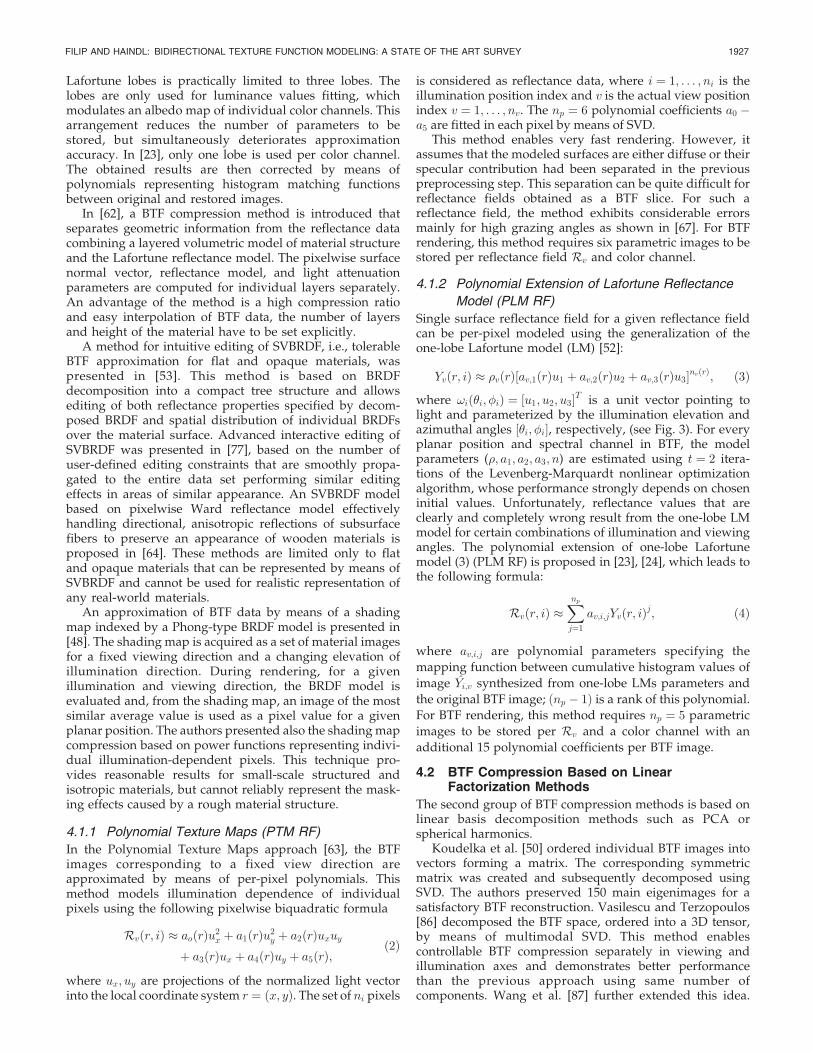
The variability of the material sample appearance inregistered and rectified BTF images is illustrated in Fig. 5.
Rough textures provide ample information about locallight field structure as well as the surface relief. Effectspresented in rough textures such as self-occlusions, self-shadowing, interreflection, or subsurface scattering arepreserved in BTF measurements (Fig. 1). A downside ofusing original measurements is their enormous storage sizesince an average sample takes several gigabytes.
Methods exist for interactive editing of measured BTF[47], which enable us to change materials properties by
IEEE TRANSACTIONS ON PATTERN ANALYSIS AND MACHINE INTELLIGENCE, VOL. 31, NO. 11, NOVEMBER 2009 1921
. The authors are with the Pattern Recognition Department, Institute ofInformation Theory and Automation of the AS CR, Pod vodarenskou vezi4, 182 08 Praha 8, Czech Republic. E-mail: {jiri.filip, haindl}@utia.cz.
Manuscript received 25 July 2007; revised 7 Apr. 2008; accepted 29 Sept.2008; published online 9 Oct. 2008.Recommended for acceptance by Y. Sato.For information on obtaining reprints of this article, please send e-mail to:[email protected], and reference IEEECS Log NumberTPAMI-2007-07-0452.Digital Object Identifier no. 10.1109/TPAMI.2008.246.
0162-8828/09/$25.00 � 2009 IEEE Published by the IEEE Computer Society

several physically nonplausible operators. However, a fastBTF synthesis method with substantial compression isessential for many applications requiring accurate real-timerendering of these data using graphics hardware. Inaddition, the original BTF measurements cannot be usedin any practical application due to missing necessarymeasurements from all arbitrary vantage points underarbitrary illumination and due to their small size. Thus, aseamless spatial enlargement (modeling) method of this,otherwise, huge BTF data is inevitable.
Contribution of the paper. The main contribution is toprovide the first thorough state-of-the-art overview of BTFmeasurement, modeling, and compression methods pub-lished so far, while selected methods are mutuallycompared in several aspects. The only survey dealing withsome parts of the complex BTF acquisition and modelingprocess is [72]. This survey provides an elegant, briefoverview of principles of BTF measurement, compression,and visualization methods and explains issues related to a
whole BTF processing pipeline from acquisition to optimalBTF rendering on graphics hardware. Although the surveyprovides useful insight into the field of BTF acquisition,compression, and rendering, it lacks rigorous side by sidecomparison of individual BTF measurement setups andcompression methods and only touches on BTF synthesis.Additionally, the mentioned survey paper does notcomprehensively mention all published methods in thefield of BTF acquisition, compression, and modeling, whileour survey does. Furthermore, a number of novel BTFacquisition, compression, and synthesis methods haveappeared since publication of the said survey [72].
In this paper, we focus mainly on thorough comparisonand categorization of the BTF measurement systems andsynthesis methods. We put the emphasis on modeling ofBTF data and rigorous comparison of the selected compres-sion and synthesis techniques. While, in [72], the para-meters of the compared methods were selected in order togive subjectively nice results and to fit within currentgraphics hardware limits, we have performed a psycho-physical experiment using several BTF samples. Ourexperiment determined BTF sample-dependent parametersof the selected tested methods providing results visuallyindiscernible from the original BTF rendering. The pro-posed psychophysical testing allowed us to prepare a faircomparison of the selected BTF compression and modelingtechniques in terms of analysis and synthesis speed,compression ratio, etc.
BTF applications in computer vision. BTF data are themost advanced and accurate digital representation of areal-world material visual properties to date and theiranalysis provides abundant information about the mea-sured material that cannot, for the majority, be attainedusing any alternative visual measurements or representa-tions, e.g., image-based relighting, bump/displacementmapping, spatially varying BRDFs, etc.
1922 IEEE TRANSACTIONS ON PATTERN ANALYSIS AND MACHINE INTELLIGENCE, VOL. 31, NO. 11, NOVEMBER 2009
Fig. 1. Examples of measured BTF samples ((a) ceiling panel,
(b) aluminum profile, and (c), (d) two fabrics) rendered on objects and
illuminated by environment lighting.
Fig. 2. Examples of leather, fabrics, aluminum, and lacquered wood BTF rendering in Mercedes C Class interior using [25] method (3D model
courtesy of DaimlerChrysler).
Fig. 3. Relationship between illumination and viewing angles within
sample coordinate system.
The nature of BTF data allows their straightforwardexploitation for design and testing of illumination [38], [85]and view-invariant features and algorithms in numerousrobust texture classification [5], segmentation, and retrievalapplications. Other image processing problems, such asimage restoration, aging modeling, face recognition, secur-ity, 3D object recognition, content-based image retrieval[85], and many other tasks can and should benefit from BTFcomprehensive information. An example of usefulness ofBTF data is a study of cast shadows by material structure in[79] and the analysis of material dimensionality in [82].Moreover, a recent psychophysical studies of these data in[22] and [21], together with a study present in this paper,has shown that analysis of different BTF samples can helpus to understand human perception of different real-worldmaterials. For all of the above-mentioned tasks, a reliableand compact representation of massive BTF data is needed.Such a representation should allow fast reconstruction andmodeling of BTF data, which is the aim of this paper. Bymodeling we understand BTF synthesis from its parametersof arbitrary size, without visible repetitions or otherdistortions, visually similar to original data.
Paper organization. Section 2 surveys principles andproperties of BTF measurements systems. Different ways ofrepresenting measured BTF data and categorization ofpublished methods are explained in Section 3. Section 4summarizes BTF compression techniques, while the subse-quent Section 5 deals with more general methods allowingsimultaneous compression and enlargement. Modelingquality criteria are the subject described in Section 6. Selectedmethods, i.e., those that are described in dedicated num-bered paragraphs in Sections 4 and 5, are further comparedand tested thoroughly with psychophysical experiment inSection 7 and Section 8 concludes the paper.
2 BTF MEASUREMENT
Since accurate and reliable BTF acquisition is not a trivialtask, only a few BTF measurement systems exist up tonow [10], [39], [50], [70], [75], [80], [89]. However, theirnumber increases every year with respect to the growingdemands for photo-realistic virtual representations of real-world materials. These systems are (similar to BRDFmeasurement systems) based on light source, video/stillcamera, and material sample. The main differencebetween individual BTF measurement systems is in thetype of measurement setup allowing four degrees offreedom for camera/light and the type of measurementsensor (CCD, video, etc.). In some systems, the camera ismoving and the light is fixed [10], [73], [80], while inothers, e.g., [50], it is just the opposite. There are alsosystems, where both camera and light source stay fixed[39], [70]. The main requirement on BTF measurements is
accurate image rectification, i.e., aligning of texture normalwith view vector, mutual registration of single BTFmeasurements for different viewpoints, and sample visualconstancy during measurement. The registration accuracystrongly depends on positioning errors of the light/camera used while the visual constancy depends onstability of material properties during a long measurementtime when exposed to an intensive light source. BTF, ifappropriately measured from real material samples, offersenough information about material properties, such asanisotropy, masking, or self-shadowing.
Pioneering work in BTF acquisition has been done byDana et al. [11], who measured a large set of variousmaterials with measurement setup based on fixed lightsource and moving camera and material sample position.The resulting CUReT BTF database has a relatively sparseangular resolution. Although individual images are notrectified to frontal view position, the authors providedimage coordinates to allow their further rectification.
Some of material measurements from the CUReTdatabase were further extended in KTH TIPS database[40]. The main purpose of the authors was to providevariations of scale in addition to pose and illumination.Such a feature is not available in any other BTF databasediscussed below. Each measured material is sampled inthree illuminations, three viewing directions, and ninescales. Measurement was performed by still camera andordinary desk light. Authors provide no rectification marksin the data images, so the database is mainly focused onmaterial classification applications. A slight variation of thisdatabase is the database KTH-TIPS2 [5], introducingadditional ambient lighting.
The BTF measurement system developed by Koudelkaet al. [50] uses fixed video camera observing materialsample positioned in a computer-controlled pan/tilt head.The sample is illuminated by an LED array mounted on arobotic arm. The system offers an impressive angularresolution and rigorous image registration. However, thespatial resolution of the resulting images is rather small,which can negatively impact many BTF modeling methods.
A BTF measurement system based on extended setup ofDana was developed by Sattler et al. [80]. The main changeis having the camera on a half-circle rail remote-controlledpositioning system. The setup provides rectified measure-ments of reasonable angular and spatial resolutions. Laterhardware upgrade and improvement of postprocessingalgorithms in this setup suppressed registration errors andenabled an even higher spatial resolution. The data setsfrom this setup were used in our experiments forcomparison of several BTF compression and modelingmethods in Section 7.
FILIP AND HAINDL: BIDIRECTIONAL TEXTURE FUNCTION MODELING: A STATE OF THE ART SURVEY 1923
Fig. 4. An example of light or camera trajectory above the sample during
measurement [80]. Fig. 5. Examples of significant material appearance change for varying
illumination/view directions, as captured by BTF for knitted wool and
lacquered wood.

The interesting idea of BTF measurement was presentedby Han and Perlin [39]. Their system consists of a triangulartapered tube made of mirrors presenting kaleidoscopicreplications of the material surface positioned under thetube. A fixed camera observes the kaleidoscopic image,where individual triangular subimages correspond to asurface observed from different viewpoints. The sample isilluminated by a digital projector illuminating individualtriangles (i.e., generating illumination positions) in thekaleidoscopic image in a shared optical pathwith the camera,using a beam splitter. The advantage of this inexpensivesystem is subpixel BTF images registration. However, thespatial resolution is limited by the camera resolution.
A dermatology BTF database, the Rutgers Skin TextureDatabase [8], contains various skin diseases taken from theillumination and camera-controlled positions. They use twomeasurement setups: a light arc (quartz halogen or fiberoptic illuminator) and camera mounted on a manuallyarticulated arm on a tripod. Data sets have either threeviewing positions and 10 illumination positions or four andeight corresponding positions. The Light Stage measuringsystem [15] was designed for similar application. It consistsof a two-axis rotation system in which a small set ofviewpoints is combined with a dense sampling of incidentalillumination.
A similar technique [26] for BTF measurement involvesa set of 5 cameras and a set of 6 lights each affixed to itsown large motorized arc surrounding the object on aturntable. Additionally, a range scanner is used to capture3D geometric data of the measured objects, so themeasured samples need not to be planar. This systemprovides a relatively coarse angular sampling.
Another BTF setup presented by Dana and Wang [12] isbased on a parabolic mirror in whose focal point is placedthe surface of the observed material sample. Illumination isintroduced by a coherent beam spatially positioned into themirror by means of a moving aperture, which enablesconvenient automated control for illumination. The samplesurface point reflectance for varying viewing directions isobserved as the image captured by a camera sharing thesame optical path with the illumination beam by means of abeam splitter. This setup provides very dense angular andspatial resolutions, but has limited maximal elevationangles and maximal sample height variations; it alsorequires long measurement times due to planar translationsused to scan the surface of the sample.
A novel measurement system of the University of Bonn[70] uses a dense array of digital still cameras uniformlymounted on a hemispherical structure. Built-in flash lightsof the cameras are used as light sources. The system enablessubpixel registration of measured images by predefinedimage transformations of individual fixed cameras andprovides high angular and spatial resolutions.
A system of similar topology, KULETH, was presentedin [73]. The system is based on a half-hemispherical chassiscontaining a spatially uniform array of illuminationsources. The material sample is placed on a turn tableand observed by a camera being positioned using a tilt arm.Resulting BTF data sets have a very high angular andmoderate spatial resolution.
BTF rendering that incorporates underlying geometrymodeling, using a mesostructure distance function, isproposed by Wang et al. [90]. The method enables fast
rendering of mesostructure silhouette in graphics hard-ware. The setup for simultaneous measurement of distancefunction and BTF is presented as well.
Finally, the acquisition system [75] uses a number ofplanar patches of the material pasted onto square backingboards with known dimensions, which are then positionedto form a pyramid-like target. This setup provides sparselysampled BTF measurements of 13 unaligned views from avariable manual camera position and the light direction issampled by moving a hand-held electronic flash. The entireBTF space is interpolated from these sparsely sampledmeasurements by means of histogram fitting and interpola-tion of steerable pyramid parameters and pixel distribu-tions. This system introduces large interpolation errors andrequires manual marking of image positions.
The surveyed BTF acquisition systems can be dividedinto two categories: systems whose authors enable a wideresearch community to use some of the measured BTFs aremore detailedly described in Table 1, while the parametersof the others systems are shown in Table 2.
The optimal BTF measurement setup design is a trickytask, heavily dependent on the required accuracy and thetarget application of the resulting BTF data. The highestillumination and view positioning accuracy requires avoid-ance of as many moving parts in the setup as possible. Ifthis cannot be achieved completely [70], [39], a simple shiftand rotation elements [12], [73], which are convenient foreasy calibration and error compensation, should be pre-ferred instead of complicated and imprecise robotic arms[11], [50], [80].
Data-consistency-critical applications can benefit fromnonuniform sampling strategies. Such systems shouldapply more dense sampling in the areas of expectedinterest, e.g., near-specular reflection, etc. This approachshould avoid missing specular peaks, etc., due to improperangular quantization steps. The resulting correct BTF datacan be resampled to a uniform quantization by a globalinterpolation algorithm in a postprocessing step if required.A disadvantage of this approach is a necessity to usemoving elements in the setup due to a variable quantizationstep, which is dependent on proximity of view and speculardirections. An interesting case of a continual sampling ofview and illumination directions is shown in [12].
For low-budget applications requiring capture of areliable look-and-feel of the material without excessiveaccuracy demands, such as Web presentation of materials,etc., an approximate acquisition setups using only sparseBTF sampling might be sufficient [5], [40], [75].
As the rectification and registration of individual imagesis one of the main sources of error in BTF data, attentionshould be paid to design of proper, unambiguous ground-true registration marks accompanying the measuredmaterial sample [50]. Idealized errorless moving parts orimmovable measurement setups can adopt a predefinedrectification transformation for each view direction, with-out the need of an additional registration procedure [70].
It should also be noted that the larger the sample to bemeasured is, the farther away the light and camera shouldbe placed to avoid a change of corresponding illuminationand viewing angles over the sample span. Thus, themaximum required size of material samples should beconsidered prior to the setup design. Similarly, a maximumheight of the measured materials should also be considered
1924 IEEE TRANSACTIONS ON PATTERN ANALYSIS AND MACHINE INTELLIGENCE, VOL. 31, NO. 11, NOVEMBER 2009

when choosing the measurement setup since there can be
principal limitation connected with some methods [12]. A
type of the acquisition sensor also influences the results.
While current video cameras allow fast response [12], [73],
they cannot deliver resolution and color representation as
well as still cameras can [70], [80].Individual BTF measurements typically suffer from
mutual registration problems. Even relatively well-rectified
and registered data [80] measured with a moving camera
contain registration errors between individual view direc-
tions, caused by inaccurate material sample position, self-
occlusion, etc. A technique to avoid self-occlusion errors is to
employ a separate compression/modeling step for each BTF
subset comprehending all images obtained for a fixed view
position. Such a BTF slice for a view direction !v is a
5D function called Fixed View Reflectance Field Rvðr1; r2; r3;�i; �iÞ, which describes the radiance of the surface point
r ¼ ðr1; r2; r3Þ, where r1; r2 are planar coordinates on a
sample and r3 is the actual spectral band.We used the BTF measurements of Bonn University [4]
as input BTF data for all methods being tested in this paper.
Six different BTF materials were used to test individual
methods. Each data set comprises 81 viewing positions nv
and 81 illumination positions ni (see Fig. 6) resulting in
6,561 images. Spatial resolution of the rectified original
measurements was M �N ¼ 800� 800 pixels.
3 DATA REPRESENTATION
AND METHODS CATEGORIZATION
The selection of proper representation of BTF data suitable
to intended application or modeling method prior to any
processing may significantly influence their final perfor-
mance. Measured BTF data can be either represented as
rectified original measurements (Fig. 6 left) or in the form of
pixelwise BRDF (Fig. 6 right), i.e., ABRDFrð�i; �i; �v; �vÞ.This BRDF is often called apparent because it can violate any
of the two basic BRDF properties, i.e., view and illumination
direction reciprocity and energy conservation. This beha-
vior can be caused by shadowing, occlusions, subsurface
scattering, and other complex effects occurring in the
material structure.
FILIP AND HAINDL: BIDIRECTIONAL TEXTURE FUNCTION MODELING: A STATE OF THE ART SURVEY 1925
TABLE 2Comparison of Different BTF Measurement Systems Parameters
Fig. 6. Two BTF representations illustrated on [80] measurements.
TABLE 1Comparison of Publicly Available BTF Databases

The first representation enables using methods basedon analysis and synthesis of whole planar texture than canbe extended to cope with texture appearance or itscorresponding parameters change dependently on illumi-nation and viewing conditions. To this category belongsampling-based approaches (Section 5.1) or probabilisticmodels (Section 5.3).
The second representation (ABRDF) describes in eachimage dependency of single pixel on illumination/viewdirection. Here, individual images describe the variance oflight/view-dependent reflectance over the measured sur-face texture. This arrangement produces specularities withlower variance in the images and allows more reliable pixel-to-pixel comparison of images than the previous arrange-ment, where the cast shadows and variable occlusion effectshave to be taken into account prior to any direct compar-ison. This representation allows us to employ a variety ofBRDF-based models (Section 4.1).
On the other hand, linear factorization approaches (e.g.,PCA, spherical harmonics) and other general statisticalmethods can be used, regardless of the BTF representation(Section 4.2).
Surveyed methods using either representation canprincipally be categorized into compression and modelingapproaches, based on their inherent or absent spatialenlargement property. While the compression methodscannot enlarge any BTF measurements by themselves andjust create more or less computationally and visuallyefficient parametrization of the original data, the modelingmethods allow unconstrained seamless spatial BTF enlarge-ment to any required size. Apart from this fundamentalutilization feature, they automatically, and often signifi-cantly, compress BTF measurements.
A basic overview of BTF compression and modelingmethods and their mutual relation in the BTF processingpipeline is shown in Fig. 7. Their principles, advantages,and shortcomings are explained in the following sections.
4 COMPRESSION METHODS
In contrast to other static planar texture representations,BTF is high-dimensional and massive. To render BTFs ongraphics hardware, their compact representation is needed.The best currently publicly available raw BTF samples [80]take up about 5 GB of storage space per material sample andtheir size can be even greater when saved in high-dynamicrange (HDR) data format. Thus, a BTF database even forsimple VR scenes can easily reach an enormous data space
range of hundreds of gigabytes; even then, these samplescannot be used in any practical applications due to theirsmall planar size.
Hence, some compression and seamless enlargement(modeling) method of these huge BTF data sets is inevitable.Such a method should provide compact parametricrepresentation and preserve main visual features of theoriginal BTF, while enabling its fast rendering takingadvantage of contemporary graphics hardware.
Several methods were published for BTF compressionbased either on reflectance models, pixelwise BRDF models,or using an approach based on standard principle compo-nent analysis (PCA). However, none of these methodsenables also texture synthesis (seamless texture enlarge-ment) without additional extension, e.g., with the aid oftiling, spatial clustering, etc. The BTF compression modelscompared in this section are described in detail in theircorresponding sections.
4.1 BTF Compression Based on Pixelwise BRDF
The first group of BTF compression methods representsBTF by means of pixelwise analytical BRDF models.McAllister et al. [65] represented the ABRDF of each pixelin BTF using the Lafortune reflectance model [52]. A similarapproach, which consists of additional lookup table scalingreflectance lobes and handling shadowing and masking,was published by Daubert et al. [13]. Spatial inconsistencyof individual pixels in BTF for different view directions ledto separate modeling of individual views (so-called viewreflectance fields Rv) in BTF. Malzbender et al. [63]represented each pixel for a given reflectance field of BTFby means of a polynomial.
Homomorphic factorization [66], similar to singularvalue decomposition (SVD), decomposes pixelwise ABRDFinto several factors of lower dimensionality; each factor isdependent on a different interpolated geometric parameter.Compared to SVD, this technique generates a factorizationwith only positive factors, enables control over smoothnessof the result, and works well with scattered, sparse datawithout a separate resampling and interpolation algorithm.Efficient multiple-term BTF approximation was suggestedby Suykens et al. in [83]. This model decomposes ABRDF ofeach pixel into a product of three or more two-dimensionalpositive factors using a technique called chained matrixfactorization. This technique uses a sequence of matrixdecompositions, each in a different parametrization, allow-ing us to obtain the multiple factor approximation. Thisdecomposition enables easier factor computation thanhomomorphic factorization [66] and its factors have lowerdynamic range, so their quantization into 8 bits for real-timerendering is much safer. A novel technique for BTFrepresentation was proposed by Ma et al. [60]. Theirapproach is based on fitting the Phong model to pixelwiseABRDF. The model’s parameters are then averaged and thedifference between original data and results of the Phongmodel, so-called spatial-varying residual function, is ap-proximated by a delta function whose parameters areobtained from a system of linear equations. This approachallows good approximation quality and interactive BTFrendering frame rates.
Meseth et al. [67] represented BTF by several pixelwiseLafortune lobes for fixed viewing direction. Due to theexpensive nonlinear fitting of its parameters, the number of
1926 IEEE TRANSACTIONS ON PATTERN ANALYSIS AND MACHINE INTELLIGENCE, VOL. 31, NO. 11, NOVEMBER 2009
Fig. 7. BTF processing scheme with basic taxonomy of compression and
modeling methods.
Lafortune lobes is practically limited to three lobes. Thelobes are only used for luminance values fitting, whichmodulates an albedo map of individual color channels. Thisarrangement reduces the number of parameters to bestored, but simultaneously deteriorates approximationaccuracy. In [23], only one lobe is used per color channel.The obtained results are then corrected by means ofpolynomials representing histogram matching functionsbetween original and restored images.
In [62], a BTF compression method is introduced thatseparates geometric information from the reflectance datacombining a layered volumetric model of material structureand the Lafortune reflectance model. The pixelwise surfacenormal vector, reflectance model, and light attenuationparameters are computed for individual layers separately.An advantage of the method is a high compression ratioand easy interpolation of BTF data, the number of layersand height of the material have to be set explicitly.
A method for intuitive editing of SVBRDF, i.e., tolerableBTF approximation for flat and opaque materials, waspresented in [53]. This method is based on BRDFdecomposition into a compact tree structure and allowsediting of both reflectance properties specified by decom-posed BRDF and spatial distribution of individual BRDFsover the material surface. Advanced interactive editing ofSVBRDF was presented in [77], based on the number ofuser-defined editing constraints that are smoothly propa-gated to the entire data set performing similar editingeffects in areas of similar appearance. An SVBRDF modelbased on pixelwise Ward reflectance model effectivelyhandling directional, anisotropic reflections of subsurfacefibers to preserve an appearance of wooden materials isproposed in [64]. These methods are limited only to flatand opaque materials that can be represented by means ofSVBRDF and cannot be used for realistic representation ofany real-world materials.
An approximation of BTF data by means of a shadingmap indexed by a Phong-type BRDF model is presented in[48]. The shading map is acquired as a set of material imagesfor a fixed viewing direction and a changing elevation ofillumination direction. During rendering, for a givenillumination and viewing direction, the BRDF model isevaluated and, from the shading map, an image of the mostsimilar average value is used as a pixel value for a givenplanar position. The authors presented also the shadingmapcompression based on power functions representing indivi-dual illumination-dependent pixels. This technique pro-vides reasonable results for small-scale structured andisotropic materials, but cannot reliably represent the mask-ing effects caused by a rough material structure.
4.1.1 Polynomial Texture Maps (PTM RF)
In the Polynomial Texture Maps approach [63], the BTFimages corresponding to a fixed view direction areapproximated by means of per-pixel polynomials. Thismethod models illumination dependence of individualpixels using the following pixelwise biquadratic formula
Rvðr; iÞ � aoðrÞu2x þ a1ðrÞu2y þ a2ðrÞuxuyþ a3ðrÞux þ a4ðrÞuy þ a5ðrÞ;
ð2Þ
where ux; uy are projections of the normalized light vectorinto the local coordinate system r ¼ ðx; yÞ. The set of ni pixels
is considered as reflectance data, where i ¼ 1; . . . ; ni is theillumination position index and v is the actual view positionindex v ¼ 1; . . . ; nv. The np ¼ 6 polynomial coefficients a0 �a5 are fitted in each pixel by means of SVD.
This method enables very fast rendering. However, itassumes that the modeled surfaces are either diffuse or theirspecular contribution had been separated in the previouspreprocessing step. This separation can be quite difficult forreflectance fields obtained as a BTF slice. For such areflectance field, the method exhibits considerable errorsmainly for high grazing angles as shown in [67]. For BTFrendering, this method requires six parametric images to bestored per reflectance field Rv and color channel.
4.1.2 Polynomial Extension of Lafortune Reflectance
Model (PLM RF)
Single surface reflectance field for a given reflectance fieldcan be per-pixel modeled using the generalization of theone-lobe Lafortune model (LM) [52]:
Yvðr; iÞ � �vðrÞ½av;1ðrÞu1 þ av;2ðrÞu2 þ av;3ðrÞu3�nvðrÞ; ð3Þwhere !ið�i; �iÞ ¼ ½u1; u2; u3�T is a unit vector pointing tolight and parameterized by the illumination elevation andazimuthal angles ½�i; �i�, respectively, (see Fig. 3). For everyplanar position and spectral channel in BTF, the modelparameters (�; a1; a2; a3; n) are estimated using t ¼ 2 itera-tions of the Levenberg-Marquardt nonlinear optimizationalgorithm, whose performance strongly depends on choseninitial values. Unfortunately, reflectance values that areclearly and completely wrong result from the one-lobe LMmodel for certain combinations of illumination and viewingangles. The polynomial extension of one-lobe Lafortunemodel (3) (PLM RF) is proposed in [23], [24], which leads tothe following formula:
Rvðr; iÞ �Xnpj¼1
av;i;jYvðr; iÞj; ð4Þ
where av;i;j are polynomial parameters specifying the
mapping function between cumulative histogram values of
image Yi;v synthesized from one-lobe LMs parameters and
the original BTF image; ðnp � 1Þ is a rank of this polynomial.
For BTF rendering, this method requires np ¼ 5 parametric
images to be stored per Rv and a color channel with an
additional 15 polynomial coefficients per BTF image.
4.2 BTF Compression Based on LinearFactorization Methods
The second group of BTF compression methods is based onlinear basis decomposition methods such as PCA orspherical harmonics.
Koudelka et al. [50] ordered individual BTF images intovectors forming a matrix. The corresponding symmetricmatrix was created and subsequently decomposed usingSVD. The authors preserved 150 main eigenimages for asatisfactory BTF reconstruction. Vasilescu and Terzopoulos[86] decomposed the BTF space, ordered into a 3D tensor,by means of multimodal SVD. This method enablescontrollable BTF compression separately in viewing andillumination axes and demonstrates better performancethan the previous approach using same number ofcomponents. Wang et al. [87] further extended this idea.
FILIP AND HAINDL: BIDIRECTIONAL TEXTURE FUNCTION MODELING: A STATE OF THE ART SURVEY 1927
Instead of using a 3D texel-illumination-view tensor, itstores BTF data directly in a 4D form, i.e., also preservingspatial relationships in individual BTF images. This helps tosignificantly decrease the reconstruction error while main-taining the same level of compression as in the previousapproach. Although, these methods enable realistic BTFrendering, they are not suitable for a fast BTF renderingapplication since they require the user to compute linearcombinations of high number of eigencomponents. A muchfaster approach, applying SVD only on images of separateview reflectance fields, was presented by Sattler et al. [80].
Another method [42] uses blockwise PCA for sceneillumination dependency coding. The coding is performedin Y-Cr-Cb color space and the resulting eigenimages arefurther compressed using a combination of cosine transfor-mation and quantization techniques.
The method described in [93] compresses pixelwiseillumination and view-dependent data by means ofspherical harmonics using up to 25 coefficients. Thecoefficient planes are further coded using a discrete wavelettransformation and the method exploits Y-Cr-Cb colorspace, which allows an even higher color compression.The authors report better visual results and compressionratios on image and video data than with standardcompression methods. A very similar approach, applyinga radial basis functions instead of spherical harmonics forpixelwise compression was introduced in [56].
Ma et al. [61] presented a method (similar to [59]) forlevel-of-details representation of BTF aimed at real-timerendering. This method is based on BTF data decomposi-tion by means of a Laplacian pyramid. BRDF vectorscorresponding to BTF at a fixed planar position atindividual pyramid levels are further approximated byPCA. The method enables significant BTF compression andreal-time rendering. The authors computed PCA forindividual reflectance fields instead of the whole BTF dataspace. This approach resulted in 16 eigenimages per oneview position, which can easily be interpolated by means ofgraphics hardware. Muller et al. [71] exploited a vectorquantization of BTF data space and each resulting clusterwas represented by a local PCA model. Some of thesecompression methods are compared in [69].
An approach to generating a full BTF from its sparesampling based on a clustering of underlying surfacegeometry was presented by Wang and Dana [88]. Thistechnique estimates a set of geometric texton patches fromexample surfaces. These patches are then used for geometrysynthesis of arbitrary view and illumination conditions andthe result is blended with results of the eigenanalysismethod. The method correctly preserves casted shadows insurface mesostructure, but cannot enlarge original BTF data.
While the above-mentioned methods do not solve theBTF synthesis problem, these methods are all capable ofcompressing the measured BTF space.
4.2.1 Reflectance Field Factorization (PCA RF)
Reflectance Field Factorization [80] is based on computationof no more than nc principal components per individualreflectance field instead of the whole BTF space. Individualimages corresponding to reflectance field Rv are used asA matrix input vectors. From matrix AAT of size ni � ni,the eigenimages Ev;k are computed by means of SVD foreach Rv together with the corresponding weights �v;k and
mean image �. The reconstruction formula for a reflectancefield is
Rvðr; iÞ �Xnck¼1
�v;kðiÞEv;kðrÞ þ �ðrÞ: ð5Þ
For the following tests, the number of components nc forindividual samples was estimated by the psychophysicalexperiment, so nc þ 1 parametric planes have to be storedper Rv.
4.2.2 BTF Space Global Factorization (PCA BTF)
In a PCA-based BTF factorization approach, Koudelka et al.[50] arranged individual color pixels of BTF images of sizeM �N in vectors forming matrix A of size 3MN � nvni.The principal components are the eigenvectors Ek of thesymmetric matrix AAT of size ninv � ninv. However, theAAT computational time for larger BTF images can beunacceptable unless using advanced incremental approx-imate techniques. Computing the eigenvectors for spatiallynonhomogeneous materials (large samples) often takesseveral days. BTF reconstruction is similar to a previousmethod stated by the following equation:
BTF ðr; i; vÞ �Xnck¼1
�kði; vÞEkðrÞ þ �ðrÞ: ð6Þ
To obtain satisfactory BTF approximation results, thenumber of preserved eigenimages nc was again set by thepsychophysical experiment. The entire BTF space is thusrepresented by nc þ 1 parametric planes.
4.2.3 BTF Space Local Factorization (LPCA BTF)
A BTF compression method well suited to contemporarygraphics hardware was presented by Muller et al. in [71].This method exploits the fact that high-dimensional datasets, in this case BTF, show a locally linear behavior. Theauthors propose a BTF compression algorithm based on acombination of iterative vector quantization and local PCAcomputed in individual clusters in BTF data. The BTFspace is iteratively divided into clusters using modifiedK-means algorithm in the planar BTF space (t denotes thenumber of iterations). The squared eigenimage reconstruc-tion error is used as a distance measure in the clusteringprocess. Each cluster is represented by means of local PCAin the form of several eigenvectors dependent on illumina-tion and viewing position. The described BTF factorizationcan be stated as
BTF ðr; i; vÞ �Xnck¼1
�mðrÞ;kðrÞEmðrÞ;kði; vÞ þ �mðrÞ; ð7Þ
where mðrÞ is a cluster index lookup table given by planarcoordinates r ¼ ðx; yÞ; nc is the number of preservedprincipal components representing each cluster, �k arePCA weights, Ek are saved eigenvectors, and �mðrÞ is themean vector for the given cluster mðrÞ. The entire BTFreconstruction together with the illumination and viewinterpolation can be implemented in graphics hardware,which enables fast BTF rendering. This method provideshigh BTF compression while ensuring high reconstructionquality and rendering speed [69]. For the following tests,the number of clusters c and number of components pereach cluster on nc were set by the psychophysical
1928 IEEE TRANSACTIONS ON PATTERN ANALYSIS AND MACHINE INTELLIGENCE, VOL. 31, NO. 11, NOVEMBER 2009
experiment. For whole BTF space representation, c clusterindex images are stored together with nc þ 1 eigenvectors ofsize ninv and nc coefficient matrices of size nc � dim ci foreach cluster i.
5 MODELING METHODS
BTF modeling methods allow seamless enlargement of BTFmeasurements to any size required by an application aswell as the reconstruction/estimation of unmeasured partsof the BTF space. These methods can be divided into threemajor groups: sampling-based, reflectance-model-based,and adaptive-probabilistic-model-based methods.
5.1 Sampling Methods
Sampling methods, which are characteristic for computergraphics applications, are based either on simple texturerepetition with edge blending or on more or less sophisti-cated image tiling methods [6], [18], [51], [81], [35] and someof them are suitable for [55] or can be adapted to BTFsynthesis, e.g., [16], [35], [81]. The most successful samplingapproaches [14], [18], [19], [41], [94] rely on sophisticatedsampling from real texture measurements, which have to bestored in the texture database. The paper by Dong andChantler [16] presents a survey of several sampling-basedBTF synthesis approaches. Based on the amount of copieddata, the sampling approaches can be divided into the per-pixel nonparametric sampling [19], [84], [91], [97] and thepatch-based sampling [35], [36], [49], [58], [99], [95]. Given arandomly selected starting block of texture in the image,they propagate out from it selecting new texture blocks. Foreach new block in the image, all neighboring blocks thathave already been generated are checked and the exampleimage (or images) is searched for similar textures. Then best such matches are found and then the correspondingnew texture patch is randomly chosen from among them.The methods [18], [19], [91] all vary in the way the blocksare represented, how similarity is determined, and how thesearch is performed.
A method similar to [89], combining a sparse set of BTFmeasurements according to an enlarged material range mapusing the [19] algorithm to generate dense BTF data wasdeveloped by Liu et al. [58]. It starts with BTF sample rangemap estimation using the shape-from-shading method. Theenlarged range map is used to guide a blockwise samplingfrom BTF measurements. The authors tested the methodperformance on CUReT data [10] only. This method is slow,overlapping blocks can potentially generate visible seams,mutual separation of analytical and synthesis parts is notpossible, and its data compression is negligible.
A modification of this method similar to [71] appeared in[59]. This method exploits technique of 3D textons, i.e., thesmallest repeatable texture elements, introduced in [57].Only these textons are then approximated using local PCAand, finally, used for surface modeling.
The pyramid matching synthesis [41] was generalized[75] for sparsely sampled BTF data, but the visual quality ofsynthesis results restricts this method to textures withoutstrong spatial characteristics.
The algorithm [84] performs BTF synthesis based onsurface textons, which extract essential information fromthe sample BTF to facilitate the synthesis. A 3D texton set isconstructed using the [57] method (BTF space clustering)
and single BTF pixels are assigned texton labels. The paperuses a general search strategy, called the k-coherent search,for constructing a neighbor candidate set. The method isextremely slow and was tested only on low-resolutionCUReT data [10]. Another sampling-based BTF synthesismethod was published by Neubeck et al. [74]. The authorsapply smart copy-and-paste smooth texture synthesis toBTF synthesis. The sampling is restricted to similarneighborhoods by introducing a reasonable subset ofpossible candidates (using the Ashikhmin’s candidatesearch [1]) from the example image. This algorithm isiterative and slow, it is restricted to small size neighbor-hoods, it might blur the resulting texture, and analysis andsynthesis cannot be separated from each other.
A generalization of the image quilting method [18] forBTF data PCA-compressed spherical harmonics expansionwas presented in [49]. This method maintains all dis-advantages of the original image quilting method, most ofall in its slowness due to unseparated analytical andsynthetical parts. The image quilting method was alsoused in an interactive application [99] allowing the user topaint BTF patches onto the surface such that the paintedpatches seamlessly integrate with the background patterns.This allows introduction of imperfections and otherirregular features into the BTF surface. However, thismethod is extremely slow; it needs 20 minutes forsynthesis of a small texture.
The BTF roller synthesis method [35], [36] is based on thefully automatic detection of one or several optimal doubletoroidal BTF patches per fixed view angle. These BTF patchesare seamlessly repeated during the synthesis step. While themethod allows only moderate texture compression, it isextremely fast due to complete separation of the analyticalstep of the algorithm from the texture synthesis part, whichhas negligible computation complexity. The method is easilyimplementable in graphical hardware for the purpose ofreal-time rendering of any type of static textures.
In [55], BTF tiling method based on Wang tiles [6] isproposed. The method cuts the tiles in spherical harmonicsBTF representation and allows real-time rendering on anarbitrary surface. The method also allows users to inter-actively edit the created BTF tiles.
All of these methods are based on some sort of originalspatial sampling of texture data or its pixelwise parametersand the best of them produce very realistic synthetictextures. However, these methods require storage of theoriginal or transformed measurements (often thousands ofimages corresponding to measured combination of viewingand illumination angles of the original target texturesample), they often produce visible seams, some of themare computationally demanding, and cannot generatetextures unseen by the algorithm. Obviously, all texturesampling techniques described in this section may beprincipally applied for spatial extension of BTF data ortheir parametric representation; however, their computa-tional costs may vary significantly and only a few of themcan perform texture rendering or relighting in real time.
5.2 Spatial Enlargement of BTF Reflectance Models
BTF reflectance models are pixelwise generalizations ofBRDF compression models, and as such they represent acompact representation/compression of BTF measurementsonly. However, they can possibly be extended with the aid
FILIP AND HAINDL: BIDIRECTIONAL TEXTURE FUNCTION MODELING: A STATE OF THE ART SURVEY 1929

of a parametric space modeling method to allow BTFspatial enlargement.
A BTF synthesis approach based on combination ofimage tiling and a pixelwise reflectance model wasintroduced in [95]. This approach involves BTF compres-sion based on polynomial texture maps [63]. Estimatedresulting parametric images containing polynomial coeffi-cients are subsequently enlarged by means of the Efrosimage quilting algorithm [18].
In [16], a survey of several BTF compression approachesis presented. The authors have tested an image-basedrelighting method [17] based on BTF image reconstructionfrom several known BTF images according to Lambertianreflectance function, overdetermined photometric stereobased on SVD of 36 images, polynomial texture maps [63],and, finally, PCA analysis of all BTF images. BTF enlarge-ment in all of these methods is accomplished again bymeans of the tiling algorithm [18].
The polynomially extended Lafortune reflectance model(PLM RF) [23], [24] was completed with the tiling method[81] applied to its parametric planes, which enables arbitraryand high-quality enlargement of BTF measurements.
5.3 Probabilistic Models
Texture synthesis based on probabilistic models [2], [3],[27], [28], [34], [37], [46], [100] requires no triflingmultidimensional models (from 3D for static color texturesup to 7D for static BTFs). If such an nD texture space canbe factorized, then these data can be modeled using a setof lower dimensional (e.g., ðn� 1ÞD) random field models,but in any case, such models are uncommon and sufferfrom several unsolved theoretical problems, which have tobe circumvented.
Unfortunately, real data space can be decorrelated onlyapproximately; hence, the independent spectral componentmodeling approach causes a loss of image information.Alternative full nD models allow unrestricted spatial-spectral correlation modeling, but their main drawback isa large amount of parameters to be estimated and, in thecase of Markov random field (MRF) models, also thenecessity of estimating all of these parameters simulta-neously. Model-based methods published so far are mostlytoo difficult to implement in current graphics hardware.
Gaussian mixtures (or their neural networks equivalent,Radial Basis Function) were used for monospectral texturesynthesis [98]. Although they are able to model nonlinearspatial interactions, their parameter estimation and synth-esis require computationally demanding numerical meth-ods—the EM algorithm and Markov Chain Monte Carlomethods. Discrete distribution mixtures of product compo-nents applied to color texture synthesis (with straightfor-ward generalization to BTF) were proposed in [27]. Thetexture synthesis is based on an easy computation ofarbitrary conditional distributions from the model, how-ever, the model requires a large training data set, powerfulcomputing resources, and its data compression is muchlower than that of the subsequent models.
Methods based on different Markov random fields [31],[29], [32], [30], combine an estimated range map withsynthetic multiscale smooth texture. These methods (except[32]) estimate a BTF texture’s range map followed by thespectral and spatial factorization of selected BTF textureimages. Due to the stochastic nature of MRF models, they
do not reproduce well regular or near-regular structures inBTF samples; hence, this regular information was intro-duced into them by means of combination of synthesizedspectral data with a relighted range map. The range map isestimated using the overdetermined photometric stereofrom mutually aligned BTF images. The overall BTF texturevisual appearance during changes of viewing and illumina-tion conditions is simulated using either bump or displace-ment mapping technique. The next step of these methods isBTF illumination/view ð�i; �i=�v; �vÞ space segmentationinto c subspace images (the closest BTF images to clustercenters) using the K-means algorithm. Eigenanalysis of BTFdata has shown that c ¼ 20 is sufficient to represent itsreflectance correctly for most of the samples. The colorcumulative histograms of individual BTF images, inperceptually uniform CIE Lab color space, are used as thedata features. These subspace images are then spectrally[29], [30] and spatially [29], [30], [32] decomposed intoband-limited monospectral factors, which are indepen-dently modeled by their dedicated 2D ([29], [30]) or 3DMRF ([32]) models.
All statistics in the models are solved analytically in theform of robust and numerically efficient Bayesian estimatorsresulting in a very compact set of parameters. Single band-limited factors (monospectral or multispectral) are subse-quently synthesized using this compact parametric set andinterpolated into fine resolution, smooth texture images.Finally, the required visual appearance of BTF is created bycombining both multispectral and range information in abump mapping or a displacement mapping filter of therendering hardware.
5.3.1 Gaussian Markov Random Field (GMRF) Model
This method [29] models the BTF subspace images by a setof dedicated 2D GMRF models and performs spectraldecorrelation of individual subspace images using Karhu-nen-Loeve (KL) transformation. The resulting monospectralfactors are further spatially decomposed by means of aGaussian-Laplacian (GL) pyramid with p levels. Individualsub-band factors are analyzed using a GMRF model, whichcan be expressed as a stationary noncausal correlated noise-driven 2D autoregressive (AR) process on image grid:
Yr ¼ �Xr þ er; ð8Þwhere � is the parameter vector, Xr is the correspondingdata vector Yr�s containing data from a symmetric con-textual neighborhood (CN) of dimensionality np, and er is arandom variable with zero mean and a constant butunknown variance �2. If individual pixel values in CN areassumed to be conditionally independent, the parameters �and �2 can be approximated analytically. The toroidal imagelattice is assumed to enable fast subspace factor synthesisfrom model parameters using inverse fast Fourier transfor-mation (FFT). In the remaining part of subspace imagesynthesis, the monospectral factors are obtained by the GLpyramid collapse and inverse KL transformation whosematrix has to be stored together with GMRF modelparameters. The analysis and synthesis of BTF data spaceusing this method is very fast, however, use of FFTsomewhat restricts this method’s hardware implementation.
1930 IEEE TRANSACTIONS ON PATTERN ANALYSIS AND MACHINE INTELLIGENCE, VOL. 31, NO. 11, NOVEMBER 2009

5.3.2 2D Causal Autoregressive (2D CAR) Model
This method [30], [31] shares a similar processing pipelineas the GMRF model. However, the method uses 2D CARmodel, which can be described as a stationary causaluncorrelated noise-driven 2D AR process:
Yr ¼ �Xr þ er: ð9ÞAlthough the meaning of the above notation is the same asin the previous GMRF model, all parameters can beestimated without simplifying approximations, er is con-trary to (8) mutually uncorrelated and CN is restricted toeither causal or unilateral, i.e., all support pixel values areknown with respect to movement on the image grid.Contrary to the previous model, the parameters � and �2
can be precisely estimated analytically and the synthesis isextremely fast by means of subsequent application of (9) onthe image grid while using estimated parameters � and awhite noise generator with variance �2. The remaining partsof the synthesis, i.e., spectral and spatial factorization arethe same as in the GRMF model.
5.3.3 3D Causal Autoregressive (3D CAR) Model
This MRF-based BTF subspace modelingmethod [32] avoidsspectral decorrelation errors due to approximate BTFspectral space decorrelation. The 3D CAR model is able torepresent all spectral correlations between individual sub-space images. Thus, the method starts directly with buildingof the GL pyramid. The model can be expressed as astationary causal uncorrelated noise-driven 3D AR process:
Yr ¼ �Xr þ Er; ð10Þwhere the CN is restricted to be causal or unilateral, � is theparameter matrix, and Er is a Gaussian white noise vectorwith zero mean and a constant but unknown covariancematrix �.
The parameters � and � are estimated analytically andthe synthesis is, for an arbitrary image size, againperformed by subsequent application of (10) on sub-bandimages’ grid. The synthesized subspace images areobtained by interpolation of GL pyramid levels. Thesynthesis using this model is very fast. However, thesimultaneous interpolation of all 3� c subspace planes ismore time-consuming and reduces the speed of fasthardware implementation.
Methods of Markov random field type are based on theestimated model in contrast to methods of prevailingintelligent sampling type, and as such they can onlyapproximate realism of the original measurement. How-ever, they offer an unbeatable data compression ratio (tensof parameters per texture only), easy simulation of evenpreviously not measured BTF images, and fast seamlesssynthesis of any texture size.
5.4 Hybrid Methods
A hybrid method of color texture modeling based onGaussian distribution mixtures (GM) was proposed [34]with the aim to combine advantages of both approaches(sampling and probabilistic modeling) to basic texturemodeling. The hybrid model can be either used to directlysynthesize color textures or to control sophisticated sam-pling from the original measurement data. In the latteroption, themethod can be viewed as a statistically controlled
sampling. It allows high visual quality of synthetic textureswhile requiring storage of only small patches of the originalmeasurements or even only Gaussian-mixture parameters inthe direct modeling version.
A generalization of the Gaussian distribution mixture-based method to BTF modeling is discussed in [33]. Thismethod estimates local statistical properties of the mono-spectral version of a fixed view target BTF texture in theform of GM of product components. The synthesizedtexture is obtained by means of a stepwise prediction ofthe whole fixed view BTF texture subspace. In order toachieve an authentic BTF texture and avoid possible loss ofhigh-frequency spatial details, optimally chosen pieces ofthe original BTF measurements are chosen in the synthesisphase. Thus, this BTF modeling method can be viewed as astatistically controlled sampling. This method allows mod-erate texture compression, high visual quality, synthesis ofarbitrary large seamless texture, and fast synthesis, but itsdrawback is time-consuming analysis and difficult GPUimplementation. An important aspect of the proposedapproach is its possible extension to multispectral ormutually registered BTF texture images.
The next method [25] performs BTF data clustering in aspatial domain. Individual clusters (ABRDFs) are storedand their spatial mapping index/image is enlarged to anarbitrary size by means of 2D CAR synthesis of pixelwisenormal vectors estimated using photometric stereo. Thistechnique allows real-time BTF rendering and compressionof about 1:300.
6 MODELING QUALITY CRITERIA
Verification of BTF data modeling quality is a difficult andstill unsolved problem due to the lack of existingmathematical criteria capable of approximating the humaneye’s perception of textures. Modeling methods directlyapproximating single pixels in their original location(reflectance models without enlargement, PCA-based com-pression) can be verified using either similar criteria tothose used in image restoration applications (e.g., L1; L2
norms) or using model of low-level human vision [9].However, stochastic models do not produce an exactpixelwise copy of an original texture, but are intended topreserve the major statistical properties of the original BTFdata. The quality of this representation depends on a chosenmodel type, its initial parameters, the support set shape andsize, direction of the image lattice movement, etc. For thisreason, any differential metrics based on pixelwise imagecomparison between original and estimated texture imagesdo not make any sense. Unfortunately, no robust criterionfor visual similarity exists. There have been severalattempts at defining texture similarity metrics, e.g., thework of Julez [43], who suggested a similarity measurebased on the second-order statistical moments. However,this promising method was questioned later by the sameauthor in [44], [45] since many counterexamples have beenshown, showing failures of the proposed similarity mea-sure. Another method based on the same assumption butusing third-order statistics was introduced in [96].Although this method seems to be more robust, it can onlydecide whether two texture images are identical or not. Thismethod does not provide any similarity measure. So it is
FILIP AND HAINDL: BIDIRECTIONAL TEXTURE FUNCTION MODELING: A STATE OF THE ART SURVEY 1931

clear that we are still missing an approach providing anacceptable and applicable measure of texture similarity.
Currently, the only reliable way is to compare theoverall visual similarity of two textures by independentobservers in a psychophysical experiment. The firstpublished psychophysical experiment using BTF datawas conducted in [68], where the authors comparedenvironmentally lit renderings of BTF [71], flat texturesmodulated by the Phong BRDF model, and photographs ofa car interior scene. The image sets from these threetechniques were the subject of a psychophysical study withthe group of 22 participants. The authors concluded thatmost participants considered the BTF model as identical tothe photographs while the BRDF representation scoredworse. Another experiment with 11 subjects in [22] studiedinfluence of various uniform BTF data resampling schemeson perceptual appearance of eight BTF samples. It hasbeen shown that different materials require differentsampling, generally downsampling of azimuthal angles ’should be preferred instead of elevation angles �, and thatillumination direction may be sampled less densely thanviewing direction. In [21] was introduced a psychophysi-cally validated metric for automatic BTF sample sizereduction based on vector quantization of BTF imagescontrolled by their mean variance.
In the following section, we performed psychophysicalexperiment to determine optimal parameter settings of therelevant tested compression methods, to obtain visuallyindiscernible results.
7 SELECTED METHODS COMPARISON
We compared nine different BTF modeling methods. Thecategorization of the methods is shown in the overviewscheme in Fig. 7 below the corresponding category blocks.The first method [81] provides tiling of the original BTFdata. The next five methods are based on pixelwisemodeling. The first three of them (Polynomial TextureMaps (PTM RF) in Section 4.1.1, Polynomial Extension ofLafortune Reflectance Model (PLM RF) in Section 4.1.2, andReflectance Field Factorization (PCA RF) in Section 4.2.1)model BTF data for individual surface reflectance fieldsseparately. The remaining two methods model the wholeBTF space at once (BTF Space Global Factorization (PCABTF) in Section 4.2.2 and BTF Space Local Factorization(LPCA BTF) in Section 4.2.3). The remaining group of threemethods is based on probabilistic modeling (2D GMRFModel in Section 5.3.1, 2D CAR Model in Section 5.3.2, and3D CAR Model in Section 5.3.3).
All of the above-described methods were compared toeach other in terms of objective and subjective visual errors,storage requirements for their parametric representation,analysis and synthesis time, and computational complexity.
All of the surveyed methods were tested on the BonnUniversity BTF data set [80]. For considerable reduction ofthe size of parametric representation of the tested pixelwisemethods and simultaneously for enabling seamless cover-ing of arbitrarily large virtual objects, an image tilingapproach was applied. The approach [81] finds suboptimalpaths in the original data to cut the required set ofarbitrarily contactable BTF tiles. The size of tiles nr � nc(see Table 7) depends strongly on the type of the underlyingmaterials’ structure, regularity, etc. All of the pixelwise BTF
models compared in this paper were further applied onlyon these BTF tiles. Six different BTF samples were tested:knitted wool, fabric dark, fabric light, synthetic leather, leather,and lacquered wood (see Fig. 11).
7.1 Psychophysical Experiment
For fair comparison of the pixelwise modeling methods, weperformed psychophysical experiment. The goal of theexperiment was to determine optimal methods’ parametersettings in order to achieve a visual appearance indis-tinguishable from the original BTF measurements. As thefirst two methods (PTM RF and PLM RF) do not allowstraightforward change of parameters, we were able tocontrol visual appearance by changing the parameters onlyfor the remaining PCA-based methods (PCA RF, PCA BTF,and LPCA BTF).
7.1.1 Experimental Data
As experimental stimuli, we used pairs of static images ofsize 800� 800 pixels showing BTF rendered on a sphere forpoint-light positioned slightly above a camera. Each pairconsisted of a rendering using the original BTF data set andone using its model in random order. For different models,we used different parameter quantization to obtain asubjectively similar range of visual degradation. The PCARF method was used with the following numbers ofprincipal components per each view direction: 2, 4, 6, 8,10, and 12. For the PCA BTF method, the quantization ofprincipal components representing the whole BTF waschosen as 10, 20, 30, 40, 50, and 60. And finally, for LPCABTF, the same parameter per cluster was quantized to 5, 8,11, 14, 17, and 20. Moreover, the number of clusters inLPCA BTF method was chosen according to the recom-mendation of the authors [71], i.e., 32 clusters per BTF size256� 256 pixels. This number of clusters was recomputedfor individual tested samples, respectively, depending onthe tile size (i.e., knitted wool 3, fabric dark 2, fabric light 3,synth. leather 6, leather 8, and lacquered wood 19). In additionto these three methods, we also added to the experimentalstimuli pairs containing renderings of the methods PTM RF,PLM RF, and original-to-original data. The describedconfiguration resulted in 156 stimuli. The background ofthe stimuli was set to dark gray. An example stimulus isshown in Fig. 8.
7.1.2 Participants
Twenty-two observers in two countries participated in theexperiment. All were either postgraduate students oracademic employees working on different research fields.
1932 IEEE TRANSACTIONS ON PATTERN ANALYSIS AND MACHINE INTELLIGENCE, VOL. 31, NO. 11, NOVEMBER 2009
Fig. 8. Example of stimulus showing (a) original and (b) improperly
parametrized sample synthetic leather.
All had normal or corrected to normal vision and all of
them were naive with respect to the purpose and design of
the experiment.
7.1.3 Experimental Procedure
Each participant was presented 156 stimuli in random order
and asked a yes-no question: Can you detect any difference in
the texture covering the objects? Participants were given as
much time as they needed for their decision. There was a
one-second pause between the stimuli and the average
participant finished the whole experiment in 30 minutes.
All stimuli were presented on calibrated 20:100 LCD displays
NEC 2090UXi and NEC 2170Nx (60 Hz, resolution
1;600� 1;200, color temperature 6,500 K, gamma 2.2, and
luminance 120 cd=m2). The experiment was performed in
controlled dim office lighting and participants were seated
at 0.8 m from the display and each sphere in the stimulus
occupied approximately 10 degree of their visual angle.
7.1.4 Fitting the Psychometric Data
When participants reported a difference between the
rendered images, their response was assigned value of 1,
and otherwise 0. By averaging the responses of all
participants, we obtained psychometric data relating
average response to variable parameter of BTF model.
There are six such data sets (one for each tested sample) for
each tested method (PCA RF, PCA BTF, LPCA BTF).The obtained psychophysical data can be represented by
psychometric function ðxÞ [92], which specifies the
relationship between the underlying probability of
positive response and the stimulus intensity x:
ðx;�; ; �; Þ ¼ � þ ð1� � � ÞF ðx;�; Þ; ð11ÞwhereF is a functionwith parameters (�; ) fitting the data, �
specifies the guess rate (i.e., response to zero stimulus), and
the miss rate (i.e., incorrect response for large stimulus).Psychometric functions were fitted to the measured data
using the psignifit package [92], based on bootstrap Monte
Carlo resampling technique for confidence interval estima-
tion of data fitting. As F we have used Weibull cumulative
distribution, which is most commonly used in life data
analysis due to its flexibility
F ðx; �; Þ ¼ 1� exp � x
�
� �� �; ð12Þ
for x � 0, where > 0 is the shape parameter and � > 0 isthe scale parameter of the distribution.
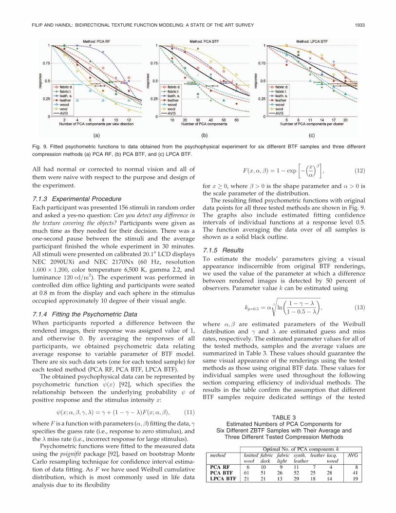
The resulting fitted psychometric functions with originaldata points for all three tested methods are shown in Fig. 9.The graphs also include estimated fitting confidenceintervals of individual functions at a response level 0.5.The function averaging the data over of all samples isshown as a solid black outline.
7.1.5 Results
To estimate the models’ parameters giving a visualappearance indiscernible from original BTF renderings,we used the value of the parameter at which a differencebetween rendered images is detected by 50 percent ofobservers. Parameter value k can be estimated using
kp¼0:5 ¼ �
ffiffiffiffiffiffiffiffiffiffiffiffiffiffiffiffiffiffiffiffiffiffiffiffiffiffiffiffiffiffiffiffiffiffiln
1� � �
1� 0:5�
� �
s; ð13Þ
where �; are estimated parameters of the Weibulldistribution and � and are estimated guess and missrates, respectively. The estimated parameter values for all ofthe tested methods, samples and the average values aresummarized in Table 3. These values should guarantee thesame visual appearance of the renderings using the testedmethods as those using original BTF data. These values forindividual samples were used throughout the followingsection comparing efficiency of individual methods. Theresults in the table confirm the assumption that differentBTF samples require dedicated settings of the tested
FILIP AND HAINDL: BIDIRECTIONAL TEXTURE FUNCTION MODELING: A STATE OF THE ART SURVEY 1933
Fig. 9. Fitted psychometric functions to data obtained from the psychophysical experiment for six different BTF samples and three different
compression methods (a) PCA RF, (b) PCA BTF, and (c) LPCA BTF.
TABLE 3Estimated Numbers of PCA Components for
Six Different ZBTF Samples with Their Average andThree Different Tested Compression Methods

method to provide results visually indiscernible from theoriginal data. This fact is justified by distinct underlyingstructure and surface roughness of the tested samples.
The remaining tested pixelwise methods (PTM RF, PLMRF) do not provide any dependent parameter, so only theiraverage observers’ responses for individual samples areshown in the first two lines of Table 4. The high values forPTM RF suggest its poor performance for all of the testedsamples, while the values of PLM RF are also often aboveaverage values of the other tested PCA-based methods. Thelast row of Table 4 shows measured guess rates � forindividual samples and their averages. These values wereobtained as incorrect responses to identical renderings, bothusing original data, and were used for initialization of thepsignifit algorithm.
7.2 Computational and Visual Quality Comparison
Pixelwise computational comparison is possible only formethods that preserve pixelwise structure of the originalBTF tiles. For this reason, a fair comparison of probabilisticmodel results is not possible to be achieved in this way. Forall other methods, the pixelwise error between original andsynthesized BTF images was computed using Mean
Average Error (MAE) in perceptually uniform CIE Labcolor space. Comparison of MAE dependence on all 81 viewdirections for all tested pixelwise methods and six differentmaterial samples is illustrated in Fig. 10.
Comparison of averaged MAE values for all viewdirections, all tested pixelwise methods, and materialsamples is presented in Table 5. In the graphs and thetable, we can see a considerable difference between PTMRF, PLM RF methods and the PCA-based methods, whoseparameters were tuned specifically for each sample bymeans of the psychophysical experiment.
For subjective visual comparison, a 3D object wasrendered using synthetic BTF data obtained by the indivi-dual tested methods. Such renderings are shown in Fig. 11again for six different tested material samples. As expected,the visual performance of the tested PCA-based methodswas quite similar due to sample-dedicated parameters set bythe experiment. The PTM RF method apparently missesspecular highlights and PLM RF slightly increases contrast,which is in accordance with Fig. 10 and Table 5.
7.3 Parametric RepresentationSize and Compression
The size of parametric representation of pixelwise BTFmodeling methods depends on a number of stored para-metric planes. These planes can represent coefficients ofunderlying models, i.e., they can be eigenimages, pixelwisepolynomial, or reflectance model parameters. For moredetailed information on parametric representation of testedmethods, see their descriptions in Sections 4.1, 4.2, and 5.3.
Table 6 provides formulas for computation of the storagesize of parametric representation for the tested methods.The compression ratio of these methods is obtained bydividing the storage size of BTF tile by the parameter
1934 IEEE TRANSACTIONS ON PATTERN ANALYSIS AND MACHINE INTELLIGENCE, VOL. 31, NO. 11, NOVEMBER 2009
TABLE 4Observers Responses on PTM RF and PLM RF Methods
and Guess Rates � for All Tested BTF Samples
Fig. 10. The comparison of individual pixelwise BTF modeling methods for six different material samples in terms of MAE in CIE Lab color space
dependent on viewing direction change (see Fig. 4) 0-the top, 81-the bottom of the hemisphere.

storage size of the respective method. Note that we assumeall parameter values as floating-point numbers; hence, bymeans of their quantization, we can achieve even highercompression for most of the tested methods.
The overall comparison of parameters storage size andcompression ratios of all nine tested methods for different
materials is shown in Table 7. The table summarizesparametric size and compression ratios of 10 BTF tiles andtheir parametric representation using the tested pixelwisemethods. Note that these values are dependent on actualsize of BTF tiles (the fourth row). The third line shows thecompression obtained by direct cutting of BTF tiles fromthe original BTF data (800� 800 pixels). The compressionachieved by probabilistic methods was computed as a ratioof raw BTF data size and the respective fixed size of thatmethod’s parametric representation. As expected, the bestcompression rates were obtained for smooth (or lessrough) samples (e.g., wood and leathers), while the wooland fabrics, exhibiting more complex effects, reachedlower values for the same visual quality. Note that thetotal compression of original BTF data achieved bycombination of BTF tiling and one of the tested compres-sion methods is obtained by multiplication of the tworespective values.
FILIP AND HAINDL: BIDIRECTIONAL TEXTURE FUNCTION MODELING: A STATE OF THE ART SURVEY 1935
TABLE 5Mean Average BTF Reconstruction Error
(in CIE Lab Color Space) of Tested Pixelwise Methods
Fig. 11. BTF results of all eight compared methods mapped on a car gearbox console for six different tested materials. Light position: right-back.
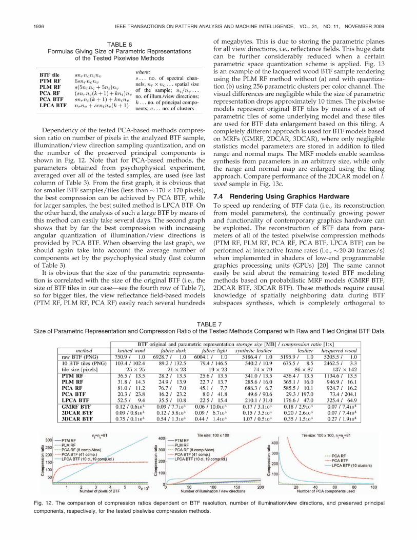
Dependency of the tested PCA-based methods compres-sion ratio on number of pixels in the analyzed BTF sample,illumination/view direction sampling quantization, and onthe number of the preserved principal components isshown in Fig. 12. Note that for PCA-based methods, theparameters obtained from psychophysical experiment,averaged over all of the tested samples, are used (see lastcolumn of Table 3). From the first graph, it is obvious thatfor smaller BTF samples/tiles (less than �170� 170 pixels),the best compression can be achieved by PCA BTF, whilefor larger samples, the best suited method is LPCA BTF. Onthe other hand, the analysis of such a large BTF by means ofthis method can easily take several days. The second graphshows that by far the best compression with increasingangular quantization of illumination/view directions isprovided by PCA BTF. When observing the last graph, weshould again take into account the average number ofcomponents set by the psychophysical study (last columnof Table 3).
It is obvious that the size of the parametric representa-tion is correlated with the size of the original BTF (i.e., thesize of BTF tiles in our case—see the fourth row of Table 7),so for bigger tiles, the view reflectance field-based models(PTM RF, PLM RF, PCA RF) easily reach several hundreds
of megabytes. This is due to storing the parametric planesfor all view directions, i.e., reflectance fields. This huge datacan be further considerably reduced when a certainparametric space quantization scheme is applied. Fig. 13is an example of the lacquered wood BTF sample renderingusing the PLM RF method without (a) and with quantiza-tion (b) using 256 parametric clusters per color channel. Thevisual differences are negligible while the size of parametricrepresentation drops approximately 10 times. The pixelwisemodels represent original BTF tiles by means of a set ofparametric tiles of some underlying model and these tilesare used for BTF data enlargement based on this tiling. Acompletely different approach is used for BTF models basedon MRFs (GMRF, 2DCAR, 3DCAR), where only negligiblestatistics model parameters are stored in addition to tiledrange and normal maps. The MRF models enable seamlesssynthesis from parameters in an arbitrary size, while onlythe range and normal map are enlarged using the tilingapproach. Compare performance of the 2DCAR model on l.wood sample in Fig. 13c.
7.4 Rendering Using Graphics Hardware
To speed up rendering of BTF data (i.e., its reconstructionfrom model parameters), the continually growing powerand functionality of contemporary graphics hardware canbe exploited. The reconstruction of BTF data from para-meters of all of the tested pixelwise compression methods(PTM RF, PLM RF, PCA RF, PCA BTF, LPCA BTF) can beperformed at interactive frame rates (i.e., �20-30 frames/s)when implemented in shaders of low-end programmablegraphics processing units (GPUs) [20]. The same cannoteasily be said about the remaining tested BTF modelingmethods based on probabilistic MRF models (GMRF BTF,2DCAR BTF, 3DCAR BTF). These methods require causalknowledge of spatially neighboring data during BTFsubspaces synthesis, which is completely orthogonal to
1936 IEEE TRANSACTIONS ON PATTERN ANALYSIS AND MACHINE INTELLIGENCE, VOL. 31, NO. 11, NOVEMBER 2009
TABLE 6Formulas Giving Size of Parametric Representations
of the Tested Pixelwise Methods
Fig. 12. The comparison of compression ratios dependent on BTF resolution, number of illumination/view directions, and preserved principal
components, respectively, for the tested pixelwise compression methods.
TABLE 7Size of Parametric Representation and Compression Ratio of the Tested Methods Compared with Raw and Tiled Original BTF Data
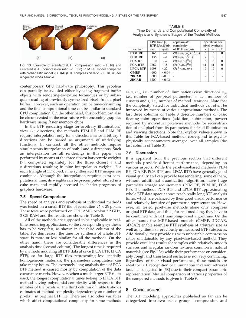
contemporary GPU hardware philosophy. This problemcan partially be avoided either by using fragment bufferobjects with rendering-to-texture techniques or by subse-quent reading of previously synthesized pixels from a pixelbuffer. However, such an operation can be time-consumingand the final computational time can be similar to standardCPU computation. On the other hand, this problem can alsobe circumvented in the near future with oncoming graphicshardware using faster memory chips.
In the BTF rendering stage for arbitrary illumination/view i=v directions, the methods PTM RF and PLM RFrequire interpolation only for v directions since arbitrary idirections can be passed as arguments of underlyingfunctions. In contrast, all the other methods requiresimultaneous interpolation of both i and v directions. Suchan interpolation for all renderings in this paper wasperformed by means of the three closest barycentric weights[7], computed separately for the three closest i andv directions resulting in nine interpolation weights. Foreach triangle of 3D object, nine synthesized BTF images arecombined. Although the interpolation requires extra com-putational time, its weights can be precomputed, stored in acube map, and rapidly accessed in shader programs ofgraphics hardware.
7.5 Speed Comparison
The speed of analysis and synthesis of individual methodswas tested on a small BTF tile of resolution 25� 25 pixels.These tests were performed on CPU AMD Athlon 2.2 GHz,3 GB RAM and the results are shown in Table 8.
All of the methods are supposed to be applicable in real-time rendering applications, so the corresponding synthesishas to be very fast, as shown in the third column of thetable. For this reason, the time for synthesis of whole BTFspace is more or less similar for all the methods. On theother hand, there are considerable differences in theanalysis time (second column). The longest time is requiredby methods modeling all BTF data at once (PCA BTF, LPCABTF), so for large BTF tiles representing less spatiallyhomogeneous materials, the parameters computation cantake many hours. The extremely long analysis time of PCABTF method is caused mostly by computation of the datacovariance matrix. However, when a much larger BTF tile isused, the longest computational times belong to LPCA BTFmethod having polynomial complexity with respect to thenumber of tile pixels n. The third column of Table 8 showsestimates of method complexity dependently on number ofpixels n in original BTF tile. There are also other variableswhich affect computational complexity for some methods
as ni=nv, i.e., number of illumination/view directions np,i.e., number of per-pixel parameters c, i.e., number ofclusters and t, i.e., number of method iterations. Note thatthe complexity stated for individual methods can often beimproved by means of various approximate methods. Thelast three columns of Table 8 describe numbers of basicfloating-point operations (addition, subtraction, power)required by individual pixelwise methods for reconstruc-tion of one pixel from its parameters for fixed illuminationand viewing directions. Note that explicit values shown inthis Table for PCA-based methods correspond to psycho-physically set parameters averaged over all samples (thelast column of Table 3).
7.6 Discussion
It is apparent from the previous section that differentmethods provide different performance, depending onvarious aspects. While the pixelwise-based methods (PLMRF, PCA RF, PCA BTF, and LPCA BTF) have generally goodvisual quality and can provide fast rendering, some of them,without additional quantization algorithm, have hugeparameter storage requirements (PTM RF, PLM RF, PCARF). The methods PCA BTF and LPCA BTF approximatingwhole BTF data space at once reach really long BTF analysistimes, which are balanced by their good visual performanceand relatively low size of parametric representation. How-ever, all tested pixelwise methods alone only compressoriginal BTF data, and thus, for real modeling, they have tobe combined with BTF sampling-based algorithms. On theother hand, the MRF-based models (GMRF, 2DCAR,3DCAR) enable seamless BTF synthesis of arbitrary size aswell as synthesis of previously unmeasured BTF subspaces.Additionally, they provide us with unbeatable compressionratios unattainable by any pixelwise-based method. Theyprovide excellent results for samples with relatively smoothsurfaces and irregular random textures common in naturalmaterials (see Fig. 13c) while their performance on consider-ably rough and translucent surfaces is not very convincing.Regardless of their visual performance, these models areideal for BTF recognition or illumination invariant retrievaltasks as suggested in [38] due to their compact parametricrepresentation. Mutual comparison of various properties ofthe compared methods is given in Table 9.
8 CONCLUSIONS
The BTF modeling approaches published so far can becategorized into two basic groups—compression and
FILIP AND HAINDL: BIDIRECTIONAL TEXTURE FUNCTION MODELING: A STATE OF THE ART SURVEY 1937
Fig. 13. Example of standard (BTF compression ratio �1 : 10) and
clustered (BTF compression ratio �1 : 100) PLM RF model compared
with probabilistic model 2D CAR (BTF compression ratio �1 : 70;000) forlacquered wood sample.
TABLE 8Time Demands and Computational Complexity of
Analysis and Synthesis Stages of the Tested Methods

modeling methods. The modeling group can be furtherclassified into sampling methods and random-field-basedmodels. Finally, a hybrid combination of both basicapproaches is possible as well. Our experience, similarly toother texture analytical tasks, shows that there is no idealBTF modeling approach. Some pixelwise compressionmethods produce excellent visual quality but their compres-sion ratio is only mild, while random-field-based modelssometimes compromise visual quality but offer extreme BTFcompression and very fast analysis as well as synthesis.Several models can easily be implemented in graphicshardware or paralleled. Some methods even allow us tomodel/interpolate previously unseen data (by modificationof the corresponding parameters) or reconstruct parts of anunmeasured BTF space. The results of selected compressionand modeling methods demonstrate their performance forsix tested BTF samples. Furthermore, the performedpsychophysical experiment showed that to obtain objec-tively the same visual performance, different BTF samplesrequire different parametric settings of the tested methods.Finally, it has to be noted that there is no ideal universal BTFmodel and the most suitable one has to be chosen dependingon the intended application (real-time, compact datarepresentation, fast GPU implementation, visual quality,etc.) as well as on the specific material sample.
ACKNOWLEDGMENTS
J. Filip was supported by the EC Marie Curie Intra-European Fellowship No 41358. He was with the Texture-Lab, School of Mathematical and Computer Sciences,Heriot-Watt University, Edinburgh, United Kingdom. Thisresearch was also supported by grants GACR 102/08/0593,1ET400750407 and partially by the M�SMT grants 1M0572and 2C06019. The authors would like to thank BonnUniversity for providing the BTF measurements, Daimler-Chrysler AG for 3D model of car interior, participants fortaking part in the experiment, and reviewers for theirvaluable and inspiring comments.
REFERENCES
[1] M. Ashikhmin, “Synthesizing Natural Textures,” Proc. ACM Symp.Interactive 3D Graphics, pp. 217-226, 2001.
[2] J. Bennett and A. Khotanzad, “Multispectral Random FieldModels for Synthesis and Analysis of Color Images,” IEEE Trans.Pattern Analysis and Machine Intelligence, vol. 20, no. 3, pp. 327-332,Mar. 1998.
[3] J. Besag, “Spatial Interaction and the Statistical Analysis of LatticeSystems,” J. Royal Statistical Soc., vol. B-36, no. 2, pp. 192-236, Feb.1974.
[4] Bonn University BTF Database, http://btf.cs.uni-bonn.de, 2003.[5] B. Caputo, E. Hayman, and P. Mallikarjuna, “Class-Specific
Material Categorisation,” Proc. Int’l Conf. Computer Vision,pp. 1597-1604, 2005.
[6] M. Cohen, J. Shade and, S.E.A. Hiller, “Wang Tiles for Image andTexture Generation,” ACM Trans. Graphics, vol. 22, no. 3, pp. 287-294, July 2003.
[7] H.S.M. Coxeter, Introduction to Geometry. Wiley, 1969.[8] O. Cula, K. Dana, F. Murphy and, B. Rao, “Bidirectional Imaging
and Modeling of Skin Texture,” IEEE Trans. Biomedical Eng.,vol. 51, no. 12, pp. 2148-2159, Dec. 2004.
[9] S. Daly, “The Visible Differences Predictor: An Algorithm for theAssessment of Image Fidelity,” Digital Images and Human Vision,pp. 179-206, 1993.
[10] K.J. Dana, S.K. Nayar, B. van Ginneken, and J.J. Koenderink,“Reflectance and Texture of Real-World Surfaces,” Proc. IEEEConf. Computer Vision and Pattern Recognition, pp. 151-157, 1997.
[11] K. Dana, B. van Ginneken, S. Nayar, and J. Koenderink,“Reflectance and Texture of Real-World Surfaces,” ACM Trans.Graphics, vol. 18, no. 1, pp. 1-34, 1999.
[12] K. Dana and J. Wang, “Device for Convenient Measurement ofSpatially Varying Bidirectional Reflectance,” J. Optical Soc.America, vol. 21, no. 1, pp. 1-12, 2004.
[13] K. Daubert, H.P.A. Lensch, W. Heidrich, and H.-P. Seidel,“Efficient Cloth Modeling and Rendering,” Proc. Conf. RenderingTechniques, pp. 63-70, 2001.
[14] J. De Bonet, “Multiresolution Sampling Procedure for Analysisand Synthesis of Textured Images,” Proc. ACM SIGGRAPH,pp. 361-368, 1997.
[15] P. Debevec, T. Hawkins, C. Tchou, H.-P. Duiker, W. Sarokin, andM. Sagar, “Acquiring the Reflectance Field of A Human Face,”Proc. ACM SIGGRAPH, pp. 145-156, July 2000.
[16] J. Dong and M. Chantler, “Comparison of Five 3D Surface TextureSynthesis Methods,” Proc. Third Int’l Workshop Texture Analysis andSynthesis, pp. 19-23, 2003.
[17] J. Dong and M. Chantler, “Capture and Synthesis of 3D SurfaceTexture,” Int’l J. Computer Vision, vol. 62, nos. 1/2, pp. 177-194,Apr. 2005.
[18] A.A. Efros and W.T. Freeman, “Image Quilting for TextureSynthesis and Transfer,” Proc. ACM SIGGRAPH, pp. 341-346, 2001.
[19] A.A. Efros and T.K. Leung, “Texture Synthesis by Non-ParametricSampling,” Proc. Int’l Conf. Computer Vision, vol. 2, pp. 1033-1038,1999.
[20] R. Fernando, M. Harris, M. Wloka, and C. Zeller, “ProgrammingGraphics Hardware,” Proc. Computer Graphics Forum, Aug. 2004.
[21] J. Filip, M. Chantler, P. Green, and M. Haindl, “A Psychophysi-cally Validated Metric for Bidirectional Texture Data Reduction,”ACM Trans. Graphics, vol. 27, no. 5, Dec. 2008.
1938 IEEE TRANSACTIONS ON PATTERN ANALYSIS AND MACHINE INTELLIGENCE, VOL. 31, NO. 11, NOVEMBER 2009
TABLE 9Attributes Rough Comparison of the Implemented BTF Modelsy

[22] J. Filip, M. Chantler, and M. Haindl, “On Optimal Resampling ofView and Illumination Dependent Textures,” Proc. Fifth Symp.Applied Perception in Graphics and Visualization, pp. 131-134, Aug.2008.
[23] J. Filip and M. Haindl, “Non-Linear Reflectance Model forBidirectional Texture Function Synthesis,” Proc. 17th Int’l Assoc.for Pattern Recognition Int’l Conf. Pattern Recognition, vol. 1, pp. 80-83, Aug. 2004.
[24] J. Filip and M. Haindl, “Efficient Image-Based BidirectionalTexture Function Model,” Proc. Fourth Int’l Workshop TextureAnalysis and Synthesis, pp. 7-12, Oct. 2005.
[25] J. Filip and M. Haindl, “BTF Modelling Using BRDF Texels,” Int’lJ. Computer Math., vol. 84, no. 9, pp. 1267-1283, Sept. 2007.
[26] R. Furukawa, H. Kawasaki, K. Ikeuchi, and M. Sakauchi,“Appearance Based Object Modeling Using Texture Database:Acquisition, Compression and Rendering,” Proc. 13th EurographicsWorkshop Rendering, pp. 257-266, 2002.
[27] J. Grim and M. Haindl, “Texture Modelling by Discrete Distribu-tion Mixtures,” Computational Statistics Data Analysis, vol. 41,nos. 3/4, pp. 603-615, Jan. 2003.
[28] M. Haindl, “Texture Synthesis,” CWI Quarterly, vol. 4, no. 4,pp. 305-331, Dec. 1991.
[29] M. Haindl and J. Filip, “Fast BTF Texture Modelling,” Proc. ThirdInt’l Workshop Texture Analysis and Synthesis, Oct. 2003.
[30] M. Haindl and J. Filip, “A Fast Probabilistic Bidirectional TextureFunction Model,” Lecture Notes in Computer Science, vol. 3212,pp. 298-305, Springer, 2004.
[31] M. Haindl and J. Filip, “Extreme Compression and Modeling ofBidirectional Texture Function,” IEEE Trans. Pattern Analysis andMachine Intelligence, vol. 29, no. 10, pp. 1859-1865, Oct. 2007.
[32] M. Haindl, J. Filip, and M. Arnold, “BTF Image Space UtmostCompression and Modelling Method,” Proc. Seventh Int’l Assoc. forPattern Recognition Int’l Conf. Pattern Recognition, vol. 3, pp. 194-197, Aug. 2004.
[33] M. Haindl, J. Grim, P. Pudil, and K.M., “A Hybrid BTF ModelBased on Gaussian Mixtures,” Proc. Fourth Int’l Workshop TextureAnalysis and Synthesis, pp. 95-100, Oct. 2005.
[34] M. Haindl, J. Grim, P. Somol, P. Pudil, and M. Kudo, “A GaussianMixture-Based Colour Texture Model,” Proc. 17th Int’l Assoc. forPattern Recognition Int’l Conf. Pattern Recognition, vol. 3, pp. 177-180, Aug. 2004.
[35] M. Haindl and M. Hatka, “A Roller—Fast Sampling-BasedTexture Synthesis Algorithm,” Proc. Int’l Conf. Central EuropeComputer Graphics, Visualization and Computer Vision, pp. 80-83,Jan. 2005.
[36] M. Haindl and M. Hatka, “BTF Roller,” Proc. Fourth Int’l WorkshopTexture Analysis and Synthesis, pp. 89-94, Oct. 2005.
[37] M. Haindl and V. Havlı�cek, “A Multiresolution Causal ColourTexture Model,” Advances in Pattern Recognition, chap. 1, pp. 114-122, Springer-Verlag, Aug. 2000.
[38] M. Haindl and P. Vacha, “Illumination Invariant TextureRetrieval,” Proc. 18th Int’l Conf. Pattern Recognition, pp. 276-279,Aug. 2006.
[39] J.Y. Han and K. Perlin, “Measuring Bidirectional TextureReflectance with a Kaleidoscope,” ACM Trans. Graphics, vol. 22,no. 3, pp. 741-748, 2003.
[40] E. Hayman, B. Caputo, M. Fritz, and J. Eklundh, “On theSignificance of Real-World Conditions for Material Classification,”Proc. Eighth European Conf. Computer Vision, pp. 253-266, 2004.
[41] D. Heeger and J. Bergen, “Pyramid Based Texture Analysis/Synthesis,” Proc. ACM SIGGRAPH, pp. 229-238, 1995.
[42] P.-M. Ho, T.-T. Wong, and C.-S. Leung, “Compressing theIllumination-Adjustable Images with Principal Component Ana-lysis,” IEEE Trans. Circuits and Systems for Video Technology, vol. 15,no. 3, pp. 355-364, Mar. 2005.
[43] B. Julesz, “Visual Pattern Discrimination,” IRE Trans. InformationTheory, vol. 8, no. 1, pp. 84-92, Feb. 1962.
[44] B. Julesz, “Textons, the Elements of Texture Perception and TheirInteractions,” Nature, vol. 290, pp. 91-97, 1981.
[45] B. Julesz, E. Gilbert, and J. Victor, “Visual Discrimination ofTextures with Identical Third-Order Statistics,” Biological Cyber-netics, vol. 31, pp. 137-140, 1978.
[46] R. Kashyap, “Analysis and Synthesis of Image Patterns by SpatialInteraction Models,” Progress in Pattern Recognition, vol. 1, pp. 149-186, Elsevier, 1981.
[47] J. Kautz, S. Boulos, and F. Durand, “Interactive Editing andModelling of Bidirectional Texture Functions,” ACM Trans.Graphics, vol. 26, no. 3, p. 53, 2007.
[48] J. Kautz, M. Sattler, R. Sarlette, R. Klein, and H.-P. Seidel,“Decoupling BRDFs from Surface Mesostructures,” Proc. GraphicsInterface Conf. ’04, pp. 177-184, 2004.
[49] H. Kawasaki, K.-D. Seo, Y. Ohsawa, and R. Furukawa, “Patch-Based BTF Synthesis for Real-Time Rendering,” Proc. IEEE Int’lConf. Image Processing, vol. 1, pp. 393-396, Sept. 2005.
[50] M. Koudelka, S. Magda, P. Belhumeur, and D. Kriegman,“Acquisition, Compression, and Synthesis of Bidirectional TextureFunctions,” Proc. Third Int’l Workshop Texture Analysis andSynthesis, pp. 47-52, Oct. 2003.
[51] V. Kwatra, A. Schodl, I. Essa, G. Turk, and A. Bobick, “GraphcutTextures: Image and Video Synthesis Using Graph Cuts,” ACMTrans. Graphics, vol. 22, no. 3 pp. 277-286, July 2003.
[52] E.P. Lafortune, S.C. Foo, K.E. Torrance, and D.P. Greenberg,“Non-Linear Approximation of Reflectance Functions,” ComputerGraphics, vol. 31, pp. 117-126, 1997.
[53] J. Lawrence, A. Ben-Artzi, C. DeCoro, W. Matusik, H. Pfister, R.Ramamoorthi, and S. Rusinkiewicz, “Inverse Shade Trees forNon-Parametric Material Representation and Editing,” ACMTrans. Graphics, vol. 25, no. 3, pp. 735-745, 2006.
[54] J. Lehtinen, “A Framework for Precomputed and Captured LightTransport,” ACM Trans. Graphics, vol. 26, no. 4, pp. 13:1-13:22,2007.
[55] C.-S. Leung, W.-M. Pang, C.-W. Fu, T.-T. Wong, and P.-A. Heng,“Tileable BTF,” IEEE Trans. Visualization and Computer Graphics,vol. 13, no. 5, pp. 935-955, Sept./Oct. 2007.
[56] C.-S. Leung, T.-T. Wong, P.-M. Lam, and K.-H. Choy, “AnRBF-Based Compression Method for Image-Based Relighting,”IEEE Trans. Image Processing, vol. 15, no. 4, pp. 1031-1041, Apr.2006.
[57] T. Leung and J. Malik, “Representing and Recognizing the VisualAppearance of Materials Using Three-Dimensional Textons,” Int’lJ. Computer Vision, vol. 43, no. 1, pp. 29-44, 2001.
[58] X. Liu, Y. Yu, and H.Y. Shum, “Synthesizing Bidirectional TextureFunctions for Real-World Surfaces,” Proc. ACM SIGGRAPH,pp. 97-106, 2001.
[59] X. Liu, J. Zhang, X. Tong, B. Guo, and H.-Y. Shum, “Synthesis andRendering of Bidirectional Texture Functions on ArbitrarySurfaces,” IEEE Trans. Visualization and Computer Graphics,vol. 10, no. 3, pp. 278-289, May/June 2004.
[60] W.-C. Ma, S.-H. Chao, B.-Y. Chen, C.-F. Chang, M. Ouhyoung, andT. Nishita, “An Efficient Representation of Complex Materials forReal-Time Rendering,” Proc. ACM Symp. Virtual Reality Softwareand Technology, pp. 150-153, 2004.
[61] W.-C. Ma, S.-H. Chao, Y.-T. Tseng, Y.-Y. Chuang, C.-F. Chang,B.-Y. Chen, and M. Ouhyoung, “Level-of-Detail Representationof Bidirectional Texture Functions for Real-Time Rendering,”Proc. 2005 Symp. Interactive 3D Graphics, pp. 187-194, Apr.2005.
[62] S. Magda and D. Kriegman, “Reconstruction of VolumetricSurface Textures for Real-Time Rendering,” Proc. 17th EurographicsWorkshop Rendering, pp. 19-29, June 2006.
[63] T. Malzbender, D. Gelb, and H. Wolters, “Polynomial TextureMaps,” Proc. ACM SIGGRAPH, pp. 519-528, 2001.
[64] S. Marschner, S. Westin, A. Arbree, and J. Moon, “Measuring andModeling the Appearance of Finished Wood,” ACM Trans.Graphics, vol. 24, no. 3, pp. 727-734, 2005.
[65] D.K. McAllister, A. Lastra, and W. Heidrich, “Efficient Renderingof Spatial Bi-Directional Reflectance Distribution Functions,”Graphics Hardware, pp. 77-88, 2002.
[66] M. McCool, J. Ang, and A. Ahmad, “Homomorphic Factorizationof BRDFs for High-Performance Rendering,” Proc. ACM SIG-GRAPH, pp. 185-194, 2001.
[67] J. Meseth, G. Muller, and R. Klein, “Preserving Realism in Real-Time Rendering of Bidirectional Texture Functions,” Proc. OpenSGSymp., pp. 89-96, Apr. 2003.
[68] J. Meseth, G. Muller, R. Klein, F. Roder, and M. Arnold,“Verification of Rendering Quality from Measured BTFs,” Proc.Third Symp. Applied Perception in Graphics and Visualization,vol. 153, pp. 127-134, July 2006.
[69] J. Meseth, G. Muller, M. Sattler, and R. Klein, “BTF Rendering forVirtual Environments,” Proc. Conf. Virtual Concepts 2003, pp. 356-363, Nov. 2003.
FILIP AND HAINDL: BIDIRECTIONAL TEXTURE FUNCTION MODELING: A STATE OF THE ART SURVEY 1939
[70] G. Muller, G. Bendels, and R. Klein, “Rapid SynchronousAcquisition of Geometry and BTF for Cultural Heritage Arte-facts,” Proc. Sixth Int’l Symp. Virtual Reality, Archaeology andCultural Heritage, pp. 13-20, 2005.
[71] G. Muller, J. Meseth, and R. Klein, “Compression and Real-TimeRendering of Measured BTFs Using Local PCA,” Proc. Conf.Vision, Modeling, and Visualisation, pp. 271-280, Nov. 2003.
[72] G. Muller, J. Meseth, M. Sattler, R. Sarlette, and R. Klein,“Acquisition, Synthesis and Rendering of Bidirectional TextureFunctions,” Proc. Eurographics 2004 State of the Art Reports, pp. 69-94, Sept. 2004.
[73] A. Neubeck, A. Zalesny, and L. Gool, “3D Texture Reconstructionfrom Extensive BTF Data,” Proc. Fourth Int’l Workshop TextureAnalysis and Synthesis, pp. 13-18, Oct. 2005.
[74] A. Neubeck, A. Zalesny, and L. Van Gool, “Viewpoint ConsistentTexture Synthesis,” Proc. Conf. 3D Data Processing, Visualizationand Transmission, pp. 388-395, Sept. 2004.
[75] A. Ngan and F. Durand, “Statistical Acquisition of TextureAppearance,” Proc. Eurographics Symp. Rendering ’05, pp. 31-40,Aug. 2006.
[76] F. Nicodemus, R.J.C.J. Hsia, I. Ginsburg, and T. Limperis,“Geometrical Considerations and Nomenclature for Reflectance,”NBS Monograph 160, Nat’l Bureau of Standards, US Dept. ofCommerce, pp. 1-52, 1977.
[77] F. Pellacini and J. Lawrence, “AppWand: Editing MeasuredMaterials Using Appearance-Driven Optimization,” ACM Trans.Graphics, vol. 26, no. 3, pp. 54:1-54:10, 2007.
[78] S.C. Pont and J.J. Koenderink, “Bidirectional Texture ContrastFunction,” Int’l J. Computer Vision, vol. 62, nos. 1/2, pp. 17-34,2005.
[79] R. Ramamoorthi, M. Koudelka, and P. Belhumeur, “A FourierTheory for Cast Shadows,” IEEE Trans. Pattern Analysis andMachine Intelligence, vol. 27, no. 2, pp. 288-295, Feb. 2005.
[80] M. Sattler, R. Sarlette, and R. Klein, “Efficient and RealisticVisualization of Cloth,” Proc. Eurographics Symp. Rendering,pp. 167-178, June 2003.
[81] P. Somol and M. Haindl, “Novel Path Search Algorithm for ImageStitching and Advanced Texture Tiling,” Proc. 13th Int’l Conf. inCentral Europe on Computer Graphics, Visualization and ComputerVision, pp. 155-162, 2005.
[82] P. Suen and G. Healey, “The Analysis and Recognition of Real-World Textures in Three Dimensions,” IEEE Trans. PatternAnalysis and Machine Intelligence, vol. 22, no. 5, pp. 491-503, May2000.
[83] F. Suykens, K. Berge, A. Lagae, and P. Dutre, “InteractiveRendering with Bidirectional Texture Functions,” ComputerGraphics Forum, vol. 22, no. 3, pp. 463-472, Sept. 2003.
[84] X. Tong, J. Zhang, L. Liu, B. Wang, X. Guo, and H.-Y. Shum,“Synthesis of Bidirectional Texture Functions on ArbitrarySurfaces,” Proc. ACM SIGGRAPH, pp. 665-672, 2002.
[85] P. Vacha and M. Haindl, “Image Retrieval Measures Based onIllumination Invariant Textural MRF Features,” Proc. Sixth ACMInt’l Conf. Image and Video Retrieval, pp. 448-454, 2007.
[86] M. Vasilescu and D. Terzopoulos, “Tensor Textures: MultilinearImage-Based Rendering,” Proc. ACM SIGGRAPH, vol. 23, no. 3pp. 336-342, Aug. 2004.
[87] H. Wang, G. Wu, L. Shi, Y. Yu, and N. Ahuja, “Out-of-Core TensorApproximation of Multi-Dimensional Matrices of Visual Data,”ACM Trans. Graphics, vol. 24, no. 3, pp. 527-535, July 2005.
[88] J. Wang and K. Dana, “Hybrid Textons: Modeling Surfaces withReflectance and Geometry,” Proc. IEEE Conf. Computer Vision andPattern Recognition, vol. 1, pp. 372-378, 2004.
[89] J. Wang and K. Dana, “Relief Texture from Specularities,” IEEETrans. Pattern Analysis and Machine Intelligence, vol. 28, no. 3,pp. 446-457, Mar. 2006.
[90] J. Wang, X. Tong, J. Snyder, Y. Chen, B. Guo, and H.-Y. Shum,“Capturing and Rendering Geometry Details for BTF-MappedSurfaces,” The Visual Computer, vol. 21, nos. 8-10, pp. 559-568,2005.
[91] L. Wei and M. Levoy, “Texture Synthesis over Arbitrary ManifoldSurfaces,” Proc. ACM SIGGRAPH, pp. 355-360, 2001.
[92] F. Wichmann and N. Hill, “The Psychometric Function: I. Fitting,Sampling, and Goodness of Fit,” Perception & Psychophysics,vol. 63, no. 8, pp. 1293-1313, 2001.
[93] T.-T. Wong and C.-S. Leung, “Compression of Illumination-Adjustable Images,” IEEE Trans. Circuits and Systems for VideoTechnology, vol. 13, no. 11, pp. 1107-1118, Nov. 2003.
[94] Y. Xu, B. Guo, and H. Shum, “Chaos Mosaic: Fast and MemoryEfficient Texture Synthesis,” Technical Report MSR-TR-2000-32,Microsoft Research, 2000.
[95] H. Yacov, T. Malzbender, and D. Gelb, “Synthesis of ReflectanceFunction Textures from Examples,” Proc. Third Int’l WorkshopTexture Analysis and Synthesis, pp. 47-52, Oct. 2003.
[96] J. Yellott, “Implications of Triple Correlation Uniqueness forTexture Statistics and the Julesz Conjecture,” J. Optical Soc. Am.,vol. 10, no. 5 pp. 777-793, May 1993.
[97] S. Zelinka and M. Garland, “Interactive Texture Synthesis onSurfaces Using Jump Maps,” Proc. 14th Eurographics WorkshopRendering, pp. 90-96, 2003.
[98] J. Zhang, D. Wang, and G. Tran, “A Wavelet-Based Multi-resolution Statistical Model for Texture,” IEEE Trans. ImageProcessing, vol. 7, no. 11, pp. 1621-1627, Nov. 1998.
[99] K. Zhou, P. Du, L. Wang, Y. Matsushita, J. Shi, B. Guo, and H.-Y.Shum, “Decorating Surfaces with Bidirectional Texture Func-tions,” IEEE Trans. Visualization and Computer Graphics, vol. 11,no. 5, pp. 519-528, Sept./Oct. 2005.
[100] S. Zhu, X. Liu, and Y. Wu, “Exploring Texture Ensembles byEfficient Markov Chain Monte Carlo—Toward A “Trichromacy”Theory of Texture,” IEEE Trans. Pattern Analysis and MachineIntelligence, vol. 22, no. 6, pp. 554-569, June 2000.
Ji�rı Filip received the MSc degree in technicalcybernetics and the PhD degree in artificialintelligence and biocybernetics from the CzechTechnical University in Prague in 2002 and2006, respectively. He is currently with thePattern Recognition Department at the Instituteof Information Theory and Automation of the ASCR, Praha, Czech Republic. He was a post-doctoral Marie Curie research fellow in theTexture Lab at the School of Mathematical and
Computer Sciences, Heriot-Watt University. Between 2002 and 2007,he was a researcher at the Institute of Information Theory andAutomation, Academy of Sciences of the Czech Republic. His currentresearch is focused on analysis, modeling, and human perception ofhigh-dimensional texture data and video sequences. He is a member ofthe IEEE.
Michal Haindl received the graduate degree incontrol engineering from the Czech TechnicalUniversity, Prague, in 1979, the PhD degree intechnical cybernetics from the CzechoslovakAcademy of Sciences in 1983, and the ScD(DrSc) degree from the Czech Technical Uni-versity in 2001. From 1983 to 1990, he worked atthe Institute of Information Theory and Automa-tion of the Czechoslovak Academy of Sciences,Prague, on different adaptive control, image
processing, and pattern recognition problems. From 1990 to 1995, hewas with the University of Newcastle; Rutherford Appleton Laboratory,Didcot; Center for Mathematics and Computer Science, Amsterdam; andInstitute National de Recherche en Informatique et en Automatique,Rocquencourt, working on several image analysis and pattern recogni-tion projects. In 1995, he rejoined the Institute of Information Theory andAutomation, where he is the head of the Pattern Recognition Department.His current research interests are random fields applications in patternrecognition and image processing and automatic acquisition of virtualreality models. He is the author of about 230 research papers published inbooks, journals, and conference proceedings. He is a fellow of the IAPRand a senior member of the IEEE.
. For more information on this or any other computing topic,please visit our Digital Library at www.computer.org/publications/dlib.
1940 IEEE TRANSACTIONS ON PATTERN ANALYSIS AND MACHINE INTELLIGENCE, VOL. 31, NO. 11, NOVEMBER 2009