ieee transactions on neural systems and … a new modality... · wanderley cardoso celeste, celso...
TRANSCRIPT

IEEE TRANSACTIONS ON NEURAL SYSTEMS AND REHABILITATION ENGINEERING, VOL. 22, NO. 3, MAY 2014 567
Towards a New Modality-Independent Interfacefor a Robotic Wheelchair
Teodiano Freire Bastos-Filho, Fernando Auat Cheein, Member, IEEE, Sandra Mara Torres Müller,Wanderley Cardoso Celeste, Celso de la Cruz, Daniel Cruz Cavalieri, Mário Sarcinelli-Filho,
Paulo Faria Santos Amaral, Elisa Perez, Carlos Miguel Soria, and Ricardo Carelli, Senior Member, IEEE
Abstract—This work presents the development of a roboticwheelchair that can be commanded by users in a supervisedway or by a fully automatic unsupervised navigation system. Itprovides flexibility to choose different modalities to command thewheelchair, in addition to be suitable for people with differentlevels of disabilities. Users can command the wheelchair based ontheir eye blinks, eye movements, head movements, by sip-and-puffand through brain signals. The wheelchair can also operate like anauto-guided vehicle, following metallic tapes, or in an autonomousway. The system is provided with an easy to use and flexible graph-ical user interface onboard a personal digital assistant, which isused to allow users to choose commands to be sent to the roboticwheelchair. Several experiments were carried out with peoplewith disabilities, and the results validate the developed system asan assistive tool for people with distinct levels of disability.
Index Terms—Assistive devices, assistive technology, biomedicaltransducers, service robots, wheelchairs.
I. INTRODUCTION
O NE of the difficulties found by people with disabilitiesis related to their mobility. Common wheelchairs require
from the user their intact manipulation ability, to use a joystickto navigate the vehicle. However, many people with disabilitiesdo not have this manipulation ability or similar mechanical de-vice, thus being unable to use this kind of wheelchair [1]. As anexample, users suffering of amyotrophic lateral sclerosis (ALS)have quite low mobility, and can loose their communication ca-pabilities, becoming locked in their own body, with low qualityof life, which generates frustration, anxiety, and depression [2].Robotic systems can improve the personal autonomy of
people with disabilities through the development of somedevices that allow them to move and to communicate. A
Manuscript received November 19, 2012; revised April 02, 2013; acceptedMay 19, 2013. Date of publication June 04, 2013; date of current version April28, 2014. This work was supported in part by FAPES/Brazil (Process 39385183/2007), in part by FACITEC/Brazil (Process 061/2007), and in part by CAPES/Brazil-SPU/Argentina (Process 044/2010 CAPG-BA).T. F. Bastos-Filho, S. M. T. Müller, W. C. Celeste, C. de la Cruz, D. C.
Cavalieri, M. Sarcinelli-Filho, and P. F. S. Amaral are with the Department ofElectrical Engineering, Federal University of Espírito Santo (UFES), 29073-910Vitória, Brazil (e-mail: [email protected]; [email protected]).F. A. Cheein is with the Department of Electronics Engineering, Univer-
sidad Tecnica Federico Santa Maria, 1680 Valparaiso, Chile (e-mail: [email protected]).E. Perez, C. M. Soria, and R. Carelli are with Instituto de Automática, Uni-
versidad Nacional de San Juan (UNSJ), J5400 San Juan, Argentina (e-mail:[email protected]).Color versions of one or more of the figures in this paper are available online
at http://ieeexplore.ieee.org.Digital Object Identifier 10.1109/TNSRE.2013.2265237
robotic wheelchair can be used for mobility for people who areunable to manipulate joysticks, providing to them some levelof mobility and freedom.Smart wheelchairs are target of studies since beginning of
1980s, with several developments in different countries, withwheelchair being commanded by eye blinks, eye movements,facial/head gestures, blowing and suck (also named “sip andpuff switch”), and brain waves, and providing navigation as-sistance to users in different ways, such as assuring collision-free travel, aiding the performance in accomplishing specifictasks (e.g., passing through doorways), and autonomously trans-porting the user between predefined locations, such as follows[3]–[11]: the wheelchair of the Smart Alec Project at StanfordUniversity (1980) used ultrasonic sensors to detect the user’sposition. The wheelchair by Madarasz (1986) of Arizona StateUniversity was also equipped with ultrasonic sensors and wasable to navigate in corridors.The NavChair of University of Michigan (1993) was built to
avoid obstacles, follow walls, and travel safely in cluttered envi-ronments using ultrasound sensors. The wheelchairs named TinMan I and Tin Man II, of KISS Institute for Practical Robotics,had three operation modes: human guided with obstacle avoid-ance, move forward along a given heading, and move to a de-sired position (Tin Man I), while Tin Man II had the capabili-ties of wall following, doorway passing, and docking to objectssuch as tables. The wheelchair of University of Pennsylvania(1994) was equipped with two legs, in addition to the four reg-ular wheels; the legs enabled the wheelchair to climb stairs andmove through rough terrain.The Wheelesley (1995) of MIT was a wheelchair equipped
with infrared proximity sensors and ultrasonic range sensors,and used switches on a panel onboard to choose among dif-ferent high level movement commands such as forward, left,right, stop, or drive backwards, and also be maneuvered withan eye tracking interface. The Smart Wheelchair (1995) of Uni-versity of Edinburgh had bump sensors to sense obstacles andhad a line following algorithm for driving through doors and be-tween rooms. The Orpheus (1996) of University of Athens wasa wheelchair equipped with 15 ultrasonic sensors for localiza-tion and obstacle avoidance, and had four basic actions: movestraight, turn left, turn right, and reverse. The wheelchair devel-oped in TAO Project (1996) of Applied AI Systems Inc., hadfunctions for collision avoidance, driving in narrow corridorsand driving through narrow doorways, using two color camerasto identify colored landmarks. The interfaces onboard were amicrophone, a keypad, and a joystick. With the voice the user
1534-4320 © 2013 IEEE. Personal use is permitted, but republication/redistribution requires IEEE permission.See http://www.ieee.org/publications_standards/publications/rights/index.html for more information.

568 IEEE TRANSACTIONS ON NEURAL SYSTEMS AND REHABILITATION ENGINEERING, VOL. 22, NO. 3, MAY 2014
was able to activate functions such as stop, turn left, turn right,and drive. The Rhombus (Reconfigurable Holonomic Omnidi-rectionalMobile Bedwith Unified Seating) ofMIT (1997) was awheelchair with omni-directional drive, and could be reconfig-ured into a bed. The RobChair (1998) of University of Coimbrawas a wheelchair equipped with five wheels, and could be oper-ated by voice, keyboard, and/or by an analog joystick. It had 12infrared sensors, four ultrasonic sensors, and one tactile bumper.The INRO (Intelligenter Rollstuhl) of University of Applied
Sciences Ravensburg–Weingarten (1998) was a wheelchairwhose main objective was to support users with disabilities innavigation and for obstacle detection. The Intelligent Wheel-chair System of Osaka University (1998), had two cameras:one facing towards the user and the other facing forward. Userprovided input to the system with head gestures, interpreted bythe inward-facing camera. The Smart Wheelchair of Universityof Plymouth (1998) used a controller based on neural networksto trace predefined paths autonomously within an art gallery.The Luoson III of National Chung Cheng University (1999)was a wheelchair equipped with a force reflection joystick,video camera, ultrasonic sensors, digital compass, gyroscope,and microphone. It had three operating modes: direct control,assistive control, and autonomous control.TheOMNI (Officewheelchair with highManeuverability and
Navigational Intelligence) of University of Hagen (1999) hadomnidirectional steering and was equipped with ultrasonic sen-sors and an infrared detector for real-time obstacle avoidanceand back tracing. The Tetranuta (1999) of University of Sevillewas a wheelchair that provided autonomous navigation by land-marks painted on the floor and landmarks in the form of radiobeacons. The Hephaestus of TRACLabs (1999) was a wheel-chair with 16 ultrasonic sensors, configured to detect obstacles.The SIAMO project at University of Alcala (1999) was used asa test bed for various input methods (voice, face/head gestures,EOG) for the wheelchair. The voice-cum-auto steer wheelchairof CEERI (India, 1999) could autonomously travel to a givendestination based on internal map or by following tape paths onfloor.The FRIEND (Functional Robot armwith user-friendly Inter-
face for Disabled people) of University of Bremen (2001) hadtwo parts: a wheelchair, and a six degree-of-freedom robot arm.Both devices were controlled by a speech recognition system.The wheelchair used stereo vision and a camera mounted inthe gripper for obstacle detection. The Rolland I (2001) ofUniversity of Bremen was a wheelchair equipped with 27 ultra-sonic sensors and a laser range finder for navigation. The MAid(Mobility Aid for Elderly and Disabled People) of University ofUlm (2001) was a wheelchair equipped with ultrasonic sensors,two infrared scanners and a laser range finder. The VAHM(acronym French for autoVehicule Autonome pour HandicapeMoteurnomous) of University of Metz (1993, 2001) was awheelchair with two versions. First, the wheelchair was placedon the top of a mobile robot base, and could follow walls andavoid obstacles. In a second version, a powered wheelchair wasused, and a grid based method was used for navigation.The Argyro’s Wheelchair of Institute of Computer Science
(Greece, 2002) could avoid obstacles and follow a person. Itwas equipped with ultrasonic sensors and an omnidirectional
camera. The WAD Project of Centre National de la RechercheScientifique (CNRS) (2002) was a wheelchair that could avoidobstacles through infrared sensors. The SmartChair of Univer-sity of Pennsylvania (2002) was equipped with wheel encoders,an omnidirectional camera, infrared sensors, a laser rangefinder, and an interaction camera, and had six behaviors (con-trol modes): hallway navigation, three-point turn (reversing andturning), obstacle avoidance, navigate through a doorway, turnwhile avoiding obstacle, and go to a specific goal. The SIRIUSof University of Seville (2002) was a wheelchair that could beteleoperated, run autonomously, or be manually controlled.The Collaborative Wheelchair Assistant of National Uni-
versity (Singapore, 2002) allowed users to travel according tosoftware-defined paths. The HaWCos of University of Siegen(2002) was a wheelchair that used muscle contractions as inputsignals. The DREAM-3 of Tottori University (2004) was awheelchair that had five action patterns: follow the left wall,follow the right wall, turn left, turn right, and drive forward.The SWCS (Smart Wheelchair Component System) of Uni-versity of Pittsburgh (2004) navigated using information fromultrasonic sensors, infrared, and bump sensors. The Victoria,of Aachen University (2004), was a wheelchair equipped withtwo computers and a touch screen, cameras, and a manipulator.The user could select, through the touch screen, an object thatthe manipulator should grasp. A grasped object could be placedon the wheelchair table, kept in the gripper, or held near theface of the user. The SPAM (Smart Power Assistance Module)of University of Pittsburgh (2005) was a wheelchair that usedinformation from different types of sensors (ultrasonic andinfrared) for navigation. Torque sensors were used to measurethe manual forces applied to the wheels such that the systemcould add additional torque to assist the user and reduce therisk of fatigue.The Rolland III of University of Bremen (2005) was a
wheelchair equipped with two laser range finders (one lockingforward and one backwards), encoders and an omnidirectionalcamera (used to find features in the environment). The TAOAicle of AIST (National Institute of Advanced Industrial Sci-ence and Technology of Japan, 2006) was a wheelchair thatused information from laser range finder, GPS, compass, andradio-frequency identification (RFID) technology for naviga-tion. The Walking Wheelchair of University of Castilla-LaMancha (2006) was equipped with four wheels and four legs.The legs made possible the wheelchair to climb stairs. TheWASTON Project of NAIST (Japan, 2001) was a wheelchairwith machine vision to interpret user’s gaze and controlling thewheelchair.The Smart Wheelchair developed in the University of Hong
Kong (2002), used neural networks to map sensor readings tocontrol actions to play back taught routes. The HURI Projectof Yonsei University (2002–2003) was a wheelchair with ma-chine vision to identify facial gestures of the user. The WADProject of Bochum University (2002) was a wheelchair that ei-ther navigated autonomously to a desired position or providedobstacle avoidance while the user navigates. The Niigata Uni-versity (2004) developed a wheelchair that used EOG signalsto command a cursor to displace in four directions (up, down,left, and right) while one blink of the eye selected the icon. The

BASTOS-FILHO et al.: TOWARDS A NEW MODALITY-INDEPENDENT INTERFACE FOR A ROBOTIC WHEELCHAIR 569
Fig. 1. Different modalities to operate the robotic wheelchair, and the corre-sponding levels of capacity. Adapted from [12].
University of Electro-communication (Japan) and University ofBoston (USA), in 2004, developed a wheelchair that could becommanded by brain waves, using 13 EEG electrodes. The Uni-versity of Zaragoza (2009) developed a wheelchair commandedby voice, blowing, and brain waves.The robotic wheelchair of Ecole Polytechnique Federale
de Lausanne (EPFL, 2010) used camera, laser and ultrasonicsensors, plus a collaborative controller, to help users to drivesafely the wheelchair commanding it through of eye move-ments. The ARTY (Assistive Robot Transport for Youngsters)of Imperial College London (2011) was a pediatric wheelchairequipped with ultrasonic and infrared sensors, which could becommanded by children through head movements (captured bya gyroscope on a hat). The IDIAP Research Institute (2011) de-veloped a wheelchair that could be commanded by brain waves.The Pohang University of Science and Technology (2012) usestongue movements to command a wheelchair, and the FederalUniversity of Espírito Santo (UFES/Brazil, 2012) developed arobotic wheelchair with a unified platform. This wheelchair isequipped with sensors to detect and avoid obstacles, and is ableto follow a predefined path or a path chosen by the user to get toa wished destination place. The commands for the wheelchaircan come from the user, through eye blinks, eye movements,head movements, sip-and-puff, or brain signals.Users with good head posture and control of head movements
may use an Inertial Measurement Unit (IMU) attached to his/herhead or a video camera installed onboard the wheelchair to cap-ture their head movements. However, users without head move-ments, but with the ability of sip-and-puff—captured by a pres-sure sensor into a straw—or blink their eyes—captured by sur-face myoelectric signals (sEMG)—could use these modalitiesto operate the wheelchair.On the other hand, people with ALS can be unable to blink
their eyes but can use their eye movements to generate com-mands, using electro-oculography (EOG)—captured by surfacemyoelectric signals—or video-oculography (VOG) methods—through a video camera.Moreover, brain waves—obtained fromelectroencephalogram (EEG)—may also be used to operate thewheelchair through a brain–computer interface (BCI).Fig. 1 presents the modalities that can be used by people
with disabilities to operate the wheelchair here developed. For
example, head mounted-IMU or camera based systems maybe the preferred alternative for those with good control of thehead, but for some users (e.g., with cerebral palsy) with noaccurate motor control of the head, sip-and-puff, eye blinksor EOG/VOG can be preferred as control modalities. EEGis a suitable alternative left for some type of users, e.g., suf-fering from locked-in syndrome. Other modalities of using thiswheelchair are as an auto-guided vehicle or as an autonomousvehicle. In addition the latter, this wheelchair has a commu-nication system onboard which allows users to communicatewith people around the wheelchair.This work is aimed at reporting a new modality-indepen-
dent interface designed to command the robotic wheelchairdeveloped by the Federal University of Espirito Santo (Brazil).Briefly, the robotic wheelchair can be commanded eitherby eye-movements, eye-blinks, face and head movements,sip-and-puff, gravitational acceleration and superficial brainsignals, with the aim of offering a solution to a wide rangeof disabilities. Additionally, the robotic wheelchair is able toperform under three behavioral modes: nonautonomous (thewheelchair is entirely controlled by the user), autonomous (afirst approach uses a SLAM (simultaneous localization andmapping) algorithm for mapping and localizing the wheelchairwithin unvisited places; and a second approach uses metal tapesplaced within a closed environment to guide the wheelchairfor autonomous navigation within it); and a semi-autonomousbehavior (the wheelchair command is shared by the user and anautonomous supervision system that prevents the wheelchairfrom collisions, dangerous or risky movements and allows forsmooth motion while navigating the environment). The entiresystem is tested as a pilot study in a population of healthy andpeople with disabilities. However, this work reports in detail theevaluation of performance of seven volunteers with differentdisabilities. The questionnaire used to evaluate the performanceof the interface and the wheelchair, as well as experimental andstatistical results showing the pros and cons of each proposal,are also included herein.This work is structured as follows. Section II introduces
the robotic wheelchair developed by the Federal Universityof Espirito Santo (Brazil), which is referenced in the sequel.Section III presents the human–machine interface (HMI) devel-oped and different modalities presented in this work. Section IVshows the navigation interface used by the modalities presentedherein. Section V presents both statistic and metric resultsof the different modalities tested in a population of sevenvolunteers with different capabilities. Section VI highlights thediscussions and conclusions of our work.
II. ROBOTIC WHEELCHAIR
The robotic wheelchair used in this work is shown in Fig. 2.Briefly, the robotic wheelchair consists of two differential mo-tors (one per each traction wheel) and a main micro-controller(ArduPilot MEGA) as low level controller. Each traction wheelhas its own optical encoder, whose measurements are sent to themicro-controller. The high level control and the interfaces de-veloped in this work, are connected to a laptop computer, whichprocesses all the incoming data. Via USB-port, the laptop com-puter sends the motion commands to the wheelchair and reads

570 IEEE TRANSACTIONS ON NEURAL SYSTEMS AND REHABILITATION ENGINEERING, VOL. 22, NO. 3, MAY 2014
Fig. 2. Robotic wheelchair with laser range sensor mounted on its footrest.
Fig. 3. Different options of communication (symbols representing needs orfeelings, or characters).
the encoders measurements. Additionally, the computer is ableto access the accelerometers readings of the ArduPilot. A rangelaser SICK is incorporated in the footrest of the wheelchair. Therange laser is used for mapping and autonomous navigation, asmentioned in Section III-G. As can be seen, the laser sensor doesnot increase the mobility restrictions of the wheelchair. Addi-tionally, a path planning algorithm presented in Section III-G2guarantees that the wheelchair will reach the desired destinationand orientation within the environment [13]. Further informa-tion regarding the wheelchair sensing and programming can befound in [13], [14].In addition, the robotic wheelchair is equipped with a com-
munication system onboard: a PDA. Such a PDA provides witha graphical user interface (GUI) with icons for communicationsymbols (characters and icons expressing needs or feelings), asillustrated in Fig. 3. They are organized in a hierarchical way,and scanned serially although, they can also be manually ac-cessed. Once a valid command is identified, a suitable prere-corded acoustic emission is transmitted to the speakers onboardthe wheelchair, according to the symbol, word, or sentence se-lected, allowing users to communicate with people around. Theuser of the wheelchair, through the PDA, is also able to inter-change among the different modalities of control presented in
Fig. 4. General architecture of the HMI developed.
this work: eye blinks, head movements, face movement, sip-and-puff, gravitational acceleration, eye movements, semi-au-tonomous navigation, and autonomous navigation.Fig. 4 illustrates how this whole system can be interchange-
able among the paradigms used to navigate the wheelchair. Theframework of the developed HMI can be divided into three mainparts.1) The signal acquisition system, which represents the acqui-sition, conditioning, preprocessing of the signals of sEMG(surface electromyogram), EEG (electro encephalogram),sip-and-puff, gravitational acceleration, and video.
2) The computational system, represented in these figures bythe block called COMPUTER, which is responsible forprocessing and classifying the information coming fromthe conditioned acquired signal. This processing unit is re-lated to the inherent processing unit of the PDA or evento a more sophisticated computational unit, such as a low-power computer (mini-ITX).
3) Output devices, which are related to command the wheel-chair, but also present a graphical interface aiming at stim-ulating the users and informing them about the chosencommand.
III. HUMAN–MACHINE INTERFACE
Fig. 4 shows the general structure of the HMI developedin this work. This interface consists of an acquisition systemthat includes amplification, filtering, digitization, recording, and

BASTOS-FILHO et al.: TOWARDS A NEW MODALITY-INDEPENDENT INTERFACE FOR A ROBOTIC WHEELCHAIR 571
processing of different kinds of signals provided by the wheel-chair user. The signals are recorded and classified in real-time,sending the identified class to a PDA. This PDA is responsibleto generate commands of movement to a computer onboard thewheelchair. Once a valid command is identified, a movementcommand is sent to the actuators of the wheelchair.As stated in Section II, the user is able to select the modality
of control of the robotic wheelchair. There are six human-basedinterfaces for controlling the vehicle (by head, face, or eyemovements, brain waves, blinks, gravitational acceleration, andsip-and-puff, as shown in Fig. 4), plus three navigation modes(autonomous, semi-autonomous, and nonautonomous). It isworth mentioning that the six human-based interfaces implythat the wheelchair will be commanded in an nonautonomousor semi-autonomous way only. The user of the wheelchair se-lects which interface or navigation mode will use. Such selec-tion is made by the assistance of another person due to the factthat, as stated in Section II, the PDA can be manually handledor by using the current interface mode (e.g., if the interfacewas previously selected to perform using eye blinks, then thefollowing interface or navigation mode can be selected by eyeblinking).Despite the selected interface modality, the biological signal
is processed and converted in commands imparted to the PDAor to the wheelchair’s motion. As the vehicles navigates withinthe environment, the loop of the architecture shown in Fig. 4is closed by means of the bio-feedback: the user receives theinformation of the motion and the environment and correctsthe commands generation by means of her/his own learning[15]. Following, each stage shown in Fig. 4 will be explainedin detail.
A. Acquisition and Processing System
The system here reported is a noninvasive one and it is de-scribed as follows.1) It determines eye blinks based on sEMG. This method re-quires the placement of surface electrodes on the temporalmuscles around the eyes.
2) The eye movements are determined based on video dataacquired through a small video camera attached to a pairof glasses (videooculography).
3) The head movements are captured using an inertial moduleunit (IMU) attached to a cap or a video camera installed infront of the wheelchair user.
4) The sip-and-puff is captured by a pressure sensor installedinto a straw.
5) The EEG waves are acquired using a commercial EEG ac-quisition equipment.
6) The face movements are acquired using an onboard visionsystem.
B. Commanding the Robotic Wheelchair by Eye Blinks
Two channels of sEMG are used to command the roboticwheelchair using eye blinks. These sEMG signals are capturedusing two electrodes located on temporal muscles, as shown inFig. 5. One channel is used for right eye muscle and the otherfor left eye muscle.
Fig. 5. Electrodes connection for the eye blinks interface modality.
Fig. 6. Robotic wheelchair commanded by eye blinks.
A simple threshold-based algorithm is used to detect the eyeblink signals. The threshold is determined from the sample data,and corresponds to the value of 35% of the maximum peak ofthe sEMG signal, to avoid false detection.The next step in confirming the valid eye-blink signal is based
on its time duration. The algorithm developed is based on the an-gular variation of each sample. The tangent to the left and to theright of the signal peak derivative is computed. Case the tangentvalue is smaller than a threshold (0.0025 was empirically used),the correspondent time instant is considered the start or the endof the valid signal.Once eye-blink signals are correctly detected, an artificial
neural network (ANN) is used to recognize the eye blinks. Asfirst step, data is down-sampled to 20 samples/s. These are thennormalized to improve the speed of convergence of the ANN.In this work, 252 test signals were obtained (84 eye blinks
of the left eye, 84 eye blinks of the right eye, and 84 randomnoises). Several supervised ANN algorithms were evaluated,and a resilient backpropagation algorithm, with four neuronsin the hidden layer and three neurons in the output layer, wasused. With this algorithm, the successful rate in recognizing eyesignals was 99.6%. Fig. 6 shows the robotic wheelchair com-manded by eye blinks.Despite the encouraging results obtained with this modality,
one of its main drawbacks is that it is not suitable for userspresenting muscle spasms or loss of muscle activity. Thus, nextsubsection presents another way to command the wheelchair,through head movements.

572 IEEE TRANSACTIONS ON NEURAL SYSTEMS AND REHABILITATION ENGINEERING, VOL. 22, NO. 3, MAY 2014
Fig. 7. Inclination sensor based on IMU attached to different devices.
Fig. 8. Obtaining the inclination angle .
Fig. 9. Robotic wheelchair commanded by a quadriplegic woman and a kidwith Duchene dystrophy through their head movements (captured by IMU).
C. Robotic Wheelchair Commanded by Head or FaceMovements
Two approaches have been provided for enabling the use ofhead movement to command the wheelchair. One approach usesan IMU attached to a cap (or other device attached to the head),mentioned as gravitational acceleration system in Section III.The second approach is a video-based system that uses an on-board video camera mounted in front of the wheelchair, fo-cusing on the user’s face.1) Head Movements Modality: A two axis IMU is used to
provide a voltage proportional to the head inclination. Thissignal is processed by a micro-controller which uses Bluetoothto communicate with the computer onboard the wheelchair[16]. Fig. 7 shows the sensor attached to a cap and the circuitdeveloped to measure head movements. Moving the headforward, to the right or to the left implies to move the roboticwheelchair forward, to the right or to the left, respectively.Moving the head to the rear causes the stop of the wheelchair.The principle for determining the head inclination angles is
based on the associated gravitational accelerations. Two inde-pendent angles should be determined to obtain the head move-ment: and angles. is the forward inclination, which is
codified to linear velocity of the robotic wheelchair while isthe side inclination, which is codified to angular velocity. Fig. 8shows how to obtain ( can be obtained exchanging by, the accelerations in the and -coordinates, respectively)
as shown in
(1)
Additionally, Fig. 9 shows the robotic wheelchair com-manded by people with disabilities through their head move-ments. The statistical results of the experimentation will beshown in Section V.2) Face Detection Modality: A standard light weight fixed
focus video camera can also be used to obtain the head move-ments by detecting the facemovements of the user. The first stepin video data analysis is to perform a histogram equalization ofthe RGB video data, aiming at improving contrasts and over-coming lighting variations. The resulted data is transformed toYCbCr space, to detect the skin color. The image is segmentedto identify the skin, using threshold values for Cb and Cr pre-viously obtained from training trials. An elliptical region of in-terest (ROI) is generated and centered at the first image momentof the segmented image. An operation AND is executed betweenthe ellipsis generated and the negative of the -component (seeFig. 10).The next step is the identification of the centroids of the re-
gions associated with both eyes and mouth. For that, data arefiltered using a Kalman filter to improve the position estimate.Three noncollinear points in the camera coordinates define a tri-angle in the image plane, as shown in Fig. 10. Changes in spacepoints, due to head and face movements, are projected onto theimage plane, thus changing the points in the image.From the point projections on the image, different angles of
the head movements can be obtained: rotation around -axis,rotation around -axis and rotation around -axis, given, re-spectively, by the following expression:
Fig. 11 shows the use of a video camera to capture images ofthe user face, making possible to command the wheelchair byhead movements [17].Despite the fact that a Kinect camera provided by Microsoft
can be also used for head motion detection, both webcam andKinect are sensitive to lightening conditions (thus restrictingthe user’s motion). Additionally, some users with cerebral palsyand with no accurate motor control of the head will not beable to use a head motion detection modality. Sip-and-puff or

BASTOS-FILHO et al.: TOWARDS A NEW MODALITY-INDEPENDENT INTERFACE FOR A ROBOTIC WHEELCHAIR 573
Fig. 10. Facial features.
Fig. 11. Robotic wheelchair commanded by face movements (captured by avideo camera).
eye movements can be preferred, which are other modalities ofcommanding thewheelchair presented in the following sections.
D. Robotic Wheelchair Commanded by Sip-and-Puff
Sip-and-puff can be used to command the wheelchairfor users with ability to blow. In this modality, a pressuresensor, installed into a straw, allows users either choosingicons of movement (at the PDA’s screen) to be executed bythe wheelchair, or choosing destination places he/she wishesthe wheelchair to go [18]. Fig. 12 shows a picture of a usercommanding the wheelchair by sip-and-puff.
E. Robotic Wheelchair Commanded by Eye Movements
A webcam attached to a pair of glasses is used to commandthe wheelchair through detecting eye movements. The ocularglobe is identified to obtain the eye movement information. Thisprocess requires a threshold identification to distinguish the iris
Fig. 12. User blows a straw to choose different options of movement or desti-nation places to be executed or reached by the wheelchair.
Fig. 13. Robotic wheelchair commanded by eye movements.
from other parts of the face. However, this technique can beinfluenced by the presence of eyebrow and eyelash, which areeliminated by applying a Hough circular random transform anda Canny filter to the image [14], [19]. The next step is to definea ROI around the eye to allow tracking the eye movements. Dueto illumination variations, a Kalman filter is used to reduce theerror in the calculus of the eye center. Thus, the eyeball positionis detected and tracked. The wheelchair user must gaze the eyeto the symbol desired on the PDA screen in order to select it.For instance, to move the robotic wheelchair forward, the usermust gaze his eye to the arrow representing the forward move-ment. Thus, the PDA will send a control signal to the computeronboard the wheelchair in order to start the desired movement(as shown in Fig. 4). Fig. 13 shows a picture of the HMI basedon eye movements.Compared to the interface based on eye blinks, the interface
based on eye tracking provides a faster way of selecting sym-bols on the PDA and is more easily adapted to the user (it is justnecessary a camera attached to a pair of glasses, as can be seenin Fig. 13). However, this interface is much more sensitive tonoise (such as lighting changing and even eye blinks, as afore-mentioned). In both cases, the user needs to calibrate the systembefore using it. It is worth mentioning that the interface basedon eye tracking is a simple and inexpensive alternative com-pared with commercial systems available in the literature [20].

574 IEEE TRANSACTIONS ON NEURAL SYSTEMS AND REHABILITATION ENGINEERING, VOL. 22, NO. 3, MAY 2014
By using the Canny filter combined with the random circularHough transform, it is possible to accurately detect the iris ofthe eyeball and thus determine a region of interest, decreasingthe influence of eyebrows and eyelashes in the calculation ofthe centroid of the iris. The use of the Kalman filter also enablesfine-tuning of the eye-tracking movement.However, there are people who cannot move the eyes, such
as people in final stage of ALS, a situation named locked-in. Forpeople with such kind of disability, another modality of wheel-chair command is discussed in next section, which considersthat most people suffering from ALS preserve their intellectualfunctions.
F. Robotic Wheelchair Commanded by Brain Waves
A BCI can use several paradigms to command a wheelchair,such as evoked potential P300 [21], motor imagery [22], ormental tasks [23]. Another paradigm is the steady state visualevoked potential (SSVEP). This potential is related to a visualflickering stimulation, and the frequency of this flickering stim-ulus will be present in the electroencephalogram (EEG) signal[24]. Hence, stimuli flickering at distinct frequencies can worksimultaneously and be associated to different classes to be iden-tified by a BCI [25].In contrast with other BCIs, an SSVEP-BCI requires little
user training and achieves high information transfer rate (ITR)[26]. Also, this kind of BCI is less susceptible to artifactsproduced by eye blinks and eye movements, because the EEGsignal, generally recorded in the occipital area, is far from thesource of such artifacts [24].Some researchers have used SSVEP-BCIs in wheelchair nav-
igation tasks, such as the works developed in [27] and [28].In [27], the interpretation of control commands generated by aSSVEP-BCI and how to use these commands in a finite statema-chine to navigate a simulated wheelchair are described. Threeexpert nonimpaired subjects participated in that study. The navi-gation task performed with this simulated wheelchair is to moveit by a corridor. However, this work did not use a real wheelchairand executed only a simple navigation task. On the other hand,the work developed in [28] presents an equipped wheelchair tobe operated from a SSVEP-BCI response. However, the wheel-chair does not present a structure that allows it to be used bypeople with disabilities, once the stimulation and the processingunits are located on the subject legs. Although this wheelchairhas an autonomous navigation system, the eight healthy partici-pants had to spend 10 min in training for BCI usage, in additionto be submitted to a previous calibration step.The SSVEP-BCI here developed can work onboard a wheel-
chair, its structure is suitable for people with disabilities and itsinterface is easy to operate and configure. Moreover, calibrationand training steps are not necessary.Twelve EEG electrodes are used, which are placed over the
occipital cortex (visual region), position P7, PO7, PO5, PO3,POz, PO4, PO6, PO8, P8, O1, O2, and Oz, according to ExtendStandard International 10–20.The users are then submitted to a visual stimulus, generated
by a FPGA subsystem, composed by four black/white checker-boards stripes flickering at 5.6 rps (top), 6.4 rps (right), 6.9 rps
Fig. 14. Robotic wheelchair commanded by the SSVEP-BCI developed.
(bottom), and 8.0 rps (left), as illustrated in Fig. 14. A yellowbar is used as biofeedback information to the user. The checker-boards flickering are measured according to their reversal pat-terns per second (rps).EEG waves are temporally and spatially filtered and then
features are extracted by a statistical test called spectral F-test(SFT). This test allows to detect phase-locked changes in theEEG signal recorded during the stimulation, , at a givenstimulus frequency, and thus to detect the evoked peaks re-lated to this stimulus. SFT is applied as the ratio between thepower in such frequency and the average power in even neigh-boring frequencies [29]
where is the power spectral density (PSD) of the signalevaluated at the frequency , and are the PSD
values at the neighbor frequencies closer to . This statis-tical test is used to detect the evoked peaks rejected by the nullhypothesis (absence of evoked response). This null hypoth-esis leads the power ratio presented above to be distributed ac-cording to an distribution. Then a critical value is obtainedfor a significance level , which is
This critical value corresponds to the rejection threshold ofthe null hypothesis , and the evoked response will be consid-ered for the values in the spectrum that are above of this criticalvalue.The features extracted are classified according to a decision
tree developed for this application. Three attributes, A1, A2, andA3, were created and a decision tree responsible for classifyingfour classes is presented in Fig. 15.The four classes are used to navigate the robotic wheelchair,
moving it forward (top stripe), to the right (right stripe), to theleft (left stripe), and stopping it (bottom stripe). Moreover, thestripes can be used to indicate or choose a final destination tothe wheelchair (Fig. 16).

BASTOS-FILHO et al.: TOWARDS A NEW MODALITY-INDEPENDENT INTERFACE FOR A ROBOTIC WHEELCHAIR 575
Fig. 15. Decision tree developed for the SSVEP-BCI.
Fig. 16. Visual stimuli used to choose the final destination.
G. Autonomous Navigation
The robotic wheelchair also provides an auto-guided optionto the user for indoor environment navigation. This mode mightbe appropriate for highly dependent users, or a user who maydesire this option to go to some specific locations in short time.Clearly, the autonomous navigation mode is aimed at reducingthe user’s effort in the generation of motion commands. It isworth mentioning that the autonomous navigation mode pro-vided by the system (see Fig. 4) allows for the autonomous mo-tion of the robotic wheelchair. However, the previously men-tioned interface modalities allow for both the command of thewheelchair and the command of the PDA.Two approaches of autonomous navigation have been devel-
oped in this work. The first approach consists of metallic tapespreviously and strategically located at the environment’s floor.Magnetic sensors are installed on the wheelchair, which detectthe metallic tracks. The second approach is an SLAM-basedpath planning and navigation. This approach uses the range lasersensor mounted in the footrest of the wheelchair (see Fig. 2)to acquire information from the environment and to generatea consistent map of it. Such a map is then used to plan andfollow different paths to destinations previously chosen by theuser through the PDA.One of the main differences among the two approaches is that
the metallic tapes-based navigation is restricted by the disposi-tion of such tapes. If a new environment needs to be accessible
Fig. 17. Details of the magnetic sensor and its location on the wheelchair (left),and the RFID reader and the metallic tracks (right).
for the wheelchair’s user, then new tapes must be placed there.However, the SLAM based navigation can be used despite theenvironment with no additional costs. One SLAM algorithm canbe applied to all the environments with similar characteristics.In this work, we use a SLAM algorithm designed to managelines—associated with walls—and corners extracted from theenvironment by means of the range laser sensor.Following, each autonomous navigation approach will be ex-
plained in detail.1) Metallic Tapes-Based Navigation: For this option,
metallic tapes on the floor are provided to define the naviga-tion path. Magnetic sensors are installed on the wheelchair,which detect the metallic tracks. In the auto-guided option, thepathway for the wheelchair along the metallic tapes, from thecurrent location to the desired destination, is determined by thecomputer. RFID tags are also installed in suitable locations,such as doors, to calibrate the odometry. It also providesacoustic feedback to the user for location awareness. Fig. 17shows the magnetic sensors and the RFID reader installedonboard the wheelchair.The pros and cons of this mode of navigation are listed in
Table I. Additionally, Fig. 18 shows an example of metallictapes disposition within an apartment. As seen, the number ofdestinations is limited by the number of labels used to iden-tify each room. It is worth mentioning that the PDA, in the au-tonomous modality interface, offers the user the different pos-sible destinations when navigating through metallic tapes. Fur-ther information regarding how the user is able to manage andchoose a destination through the PDA can be found in [30].Briefly, the PDA displays all the available labels (related to theenvironment intended to navigate), and the user chooses onelabel as a destination (e.g., kitchen). Then, the wheelchair fol-lows the metallic tapes by using its magnetic sensors as shownin Fig. 17. The position estimation is mainly based on odometricmeasurements, but RFID sensors are the ones that communicatethe wheelchair that the user has reached the destination goal.It is worth mentioning that the low level controller that relates
the magnetic sensor readings with the motion commands is aPID controller. Additionally, we have set the maximum linearspeed of the robotic wheelchair to 0.5 m/s, whereas the max-imum rotational speed was set to 0.4 rad/s.2) Slam-Based Navigation: Although metallic tapes are used
along the path and magnetic sensors are used to detect them inorder to allow the wheelchair to navigate through fixed ways,

576 IEEE TRANSACTIONS ON NEURAL SYSTEMS AND REHABILITATION ENGINEERING, VOL. 22, NO. 3, MAY 2014
TABLE IPROS AND CONS OF METALLIC TAPES-BASED NAVIGATION
Fig. 18. Example of metallic tapes disposition (in solid red) within an apart-ment model.
such navigation strategy is highly restricted by the metallictapes disposition, as shown in Table I. In order to fulfil thedrawbacks shown by the previous navigation strategy, a SLAMalgorithm is implemented in the robotic wheelchair system[31]. The SLAM algorithm uses the range readings—from thelaser sensor mounted in the footrest of the wheelchair, as shownin Fig. 2—to concurrently localize the wheelchair within theenvironment and to build a geometric model—map—of suchan environment. The latter is achieved by the implementationof an EKF (Extended Kalman Filter) based SLAM, that ex-tracts corners—concave and convex—and lines—associatedwith walls—from the environment. The programming andoptimization issues, and consistency results of the implementedEKF-SLAM can be found in a previous work of the authors[15], [32]. It is worth mentioning that the SLAM algorithm perse, is not a navigation strategy. It is an approach that can be
Fig. 19. Scheme of the SLAM algorithm as a secondary process duringnavigation.
used by a navigation strategy to enhance its performance. Inthis work, we have used the SLAM algorithm in the followingsituations:1) to obtain an accurate map of an environment;2) to allow for the performing of risky maneuvers.To Obtain an Accurate Map: Considering that the aim of
the SLAM algorithm is to build a map of the surrounding en-vironment, such an algorithm performs as a secondary processwhereas a user modality interface governs the wheelchair’s mo-tion, as shown in Fig. 19. An implemented example of this sit-uation can be found in [15].In Fig. 19, the user commands the wheelchair’s motion
through one of the modalities previously presented. The con-trol commands as well as the laser sensor readings from theenvironment are the inputs of the EKF-SLAM algorithm [32].The SLAM algorithm returns the instantaneous position of thewheelchair within the environment and a map of such envi-ronment. Thus, the SLAM algorithm is used only to model theenvironment that surrounds the wheelchair’s navigation and toestimate the wheelchair’s position. It is worth mentioning thatthe map of the environment and the position of the wheelchairwithin that environment, are obtained from the SLAM systemstate [32]. Furthermore, the SLAM algorithm is activated oncethe user selects the semi-autonomous navigation option shownin Fig. 4.Additionally, the map of the environment can be stored within
the wheelchair’s onboard computer for future navigation pur-poses [30]. Fig. 20 shows an example of a map obtained from theEKF-SLAM algorithm used in this work. The magenta pointsare raw laser data, the solid dark segments are associated withextracted lines from the environment, whereas the green circlesare the detected corners. The dotted blue line is the path traveledby the robotic wheelchair [13].
To Allow for the Performing of Risky Maneuvers: Basedon the SLAM system state, we have available informationregarding the environment surrounding the robotic wheelchair.Such information is used for two specific cases: crossing adoor and turning within passageways. Both situations, althoughtrivial, are of great efforts for the wheelchair’s user. Thecrossing-a-door problem requires of precision, whereas theturning process requires precision and information regardingbackward movements. The SLAM algorithm, in this case,

BASTOS-FILHO et al.: TOWARDS A NEW MODALITY-INDEPENDENT INTERFACE FOR A ROBOTIC WHEELCHAIR 577
Fig. 20. Example of map obtained by the EKF-SLAM implemented in thiswork.
Fig. 21. General architecture of the SLAM-based crossing-a-door solution.
provides the necessary information to perform both processproperly.The crossing-a-door problem is summarized in Fig. 21.The system architecture shown in Fig. 21 can be briefly sum-
marized as follows.• Within the dashed red line are the user-modality stages ofthe proposed architecture. The HMI (as the ones shown inthis section) receives the user’s physiological signals andgenerates motion commands with them, which are then im-parted to the motorized wheelchair. In addition, the inter-face communicates to the user when a door has been de-tected. If more than one door was detected, the interfaceallows the user to choose which door to cross. The latter isaccomplished by means of the same signals used to com-mand the wheelchair’s motion (see [33] for further details).If no door is chosen to cross, then the wheelchair motioncontrol remains under the user decision. It is worth men-tioning that the user’s control stage is closed by a cognitivebio-feedback loop based on both the environment informa-tion and the perception of the wheelchair motion accordingto the user (dashed green line) [15].
• The range laser sensor mounted on the wheelchair’sfootrest shown in Fig. 2, is used to acquire the informationregarding the surrounding environment. The raw rangedata acquired by the sensor is processed for doors detec-tion and environmental features extraction. In particular,
the door detection procedure is based on the histogrammethod [33] which obtains the Cartesian position of a doorwith respect to a reference frame attached to the vehicle.The features extracted from the environment correspondto lines—associated with walls—and corners—convexand concave. The detected doors and the features acquiredfrom the environment are used by the SLAM algorithm. Itis worth mentioning that the position of the detected doorsis also part of the SLAM system state and it is used forlocalization purposes of the wheelchair.
• The map estimated by the SLAM algorithm is used forplanning purposes. The Frontier PointsMethod [33] is usedto locally plan a feasible and safe path between the wheel-chair’s position and the middle point of the door chosenby the user. The Frontier Points Method guarantees thata free collision path can be found within the mapped en-vironment. Such a path is update at each sampling timeof the SLAM algorithm. The reference path generated bythe path planning stage is compared to the vehicle esti-mated position and such a comparison is fed to the trajec-tory controller. The trajectory controller used in our workis an adaptive trajectory controller with exponential sta-bility [33].
If the user chooses to cross a detected door, then the controlof the wheelchair switches to the trajectory controller. Hence,the crossing-a-door problem is performed autonomously. It isworth mentioning that the SLAM algorithm starts once the userchooses a detected door from the environment. After crossingthe detected door, the SLAM memory usage is released fromthe onboard computer. More information regarding this imple-mentation can be found in a previous work of the authors [33].The second SLAM-based maneuver is a turning strategy
that allows the user of the wheelchair to autonomously reacha desired orientation within a narrowed environment. Thisapproach is useful for patients that present muscle spasms orloss of muscle activity, due to the great effort they have to makein order to perform backward movements. Briefly, the turningstrategy uses the SLAM-based map for planning a suitable andsafe collision path to be followed, autonomously, by the roboticwheelchair. Details of this implementation can be found in[13]. The method can be summarized as follows.1) A visual interface allows the user to choose the desiredorientation.
2) The computational system uses the map built by theSLAM algorithm and the estimate of the wheelchair po-sition within the environment to check if there is enoughspace available for a safe navigation.
3) Following, a Monte Carlo based semi-circle generationsearches for the minimum cost path based on successivegeneration of semi-circles of variable radius, as shown inFig. 22 [13].
4) Once a path is found, a trajectory controller drives thewheelchair until it reaches a neighborhood of the desiredorientation.
The proposed turning strategy guarantees the existence of asolution. Further details of this method can be found in [13].Additionally, Fig. 22 shows an example of the turning strategy.

578 IEEE TRANSACTIONS ON NEURAL SYSTEMS AND REHABILITATION ENGINEERING, VOL. 22, NO. 3, MAY 2014
Fig. 22. Example of the turning strategy.
Fig. 23. Architecture of the semi-autonomous navigation.
In Fig. 22, the desired orientation is 180 from the currentwheelchair’s orientation—useful for passageways navigation–;the initial orientation of the wheelchair is . Thesolid dark square represents the wheelchair within the environ-ment; the solid green lines represent the successively feasiblepaths found by the system, whereas the solid magenta path isthe one chosen as the optimum (according to a cost criterionpresented in [13]). The solid grey segments are associatedwith lines extracted from the environment, whereas the solidblue rectangle circumscribes the map in order to restrict themaneuverability area. As can be seen, all feasible paths ensurea safe turning.Once a path is chosen, the same trajectory controller pre-
sented in [33] is implemented to drive the wheelchair’s motionuntil reaching the desired orientation.
H. Semi-Autonomous Navigation
Despite the user-dependent modalities shown in Fig. 4, thesystem can take the advantages of the autonomous implemen-tation shown in Section III-G2 to assist the user on the wheel-chair ([34]). With this insight, a semi-autonomous modality isproposed.This modality assists the user in a secondary way (as shown
in Fig. 23) and it is explained as follows.• Once the user chooses to control the robotic wheelchairin a semi-autonomous way, the only changes experiencedby the user is in the control of the device. Thus, the inter-face remains the same. In fact, it could be one of the sevenmodalities presented in this work (shown in Fig. 4): eye
blink, eye movement, face movement, head movement, ac-celeration, sip-and-puff and brain waves.
• The control of the wheelchair is based on a fusion of theuser’s command generation through her/his modality andfour autonomous executions: crossing-a-door, turning ma-neuvers, emergency stops, and velocity restrictions, whichare automatically executed once the user chooses the semi-autonomous navigation modality.
• Such four automatic executions are aimed at protecting andassisting the user in the following manner.1) Crossing-a-door: the strategy presented inSection III-G2 for detecting and crossing doors isexecuted. It is always processing range data (acquiredfrom the laser implemented at the wheelchair’sfootrest, as shown in Fig. 2) in order to detect possibledoors. Once a door (or more) is detected, it shows tothe user the detected doors through the PDA. If theuser chooses to cross such a door, then the SLAMalgorithm is used to fulfil the task, as previouslystated. The user is also able to ignore the detecteddoors and continue the navigation (in [33], furtherdetails are provided regarding the crossing-a-doorsystem).
2) Turning maneuvers: if the system detects that thewheelchair is maneuvering within confined spaces,the option of turning is automatically visible in thePDA. The details regarding how the system detectsthe restrictions in the workspace can be found in aprevious work of the authors [13].
3) Emergency stops: the laser mounted at the wheel-chair’s footrest is always acquiring readings fromthe environment. If the wheelchair is too close to adetected obstacle (e.g., a person blocking the pas-sageway) the wheelchair stops its navigation andblocks further movements in the direction of collision.Thus, the emergency stop stage prevents the user ofcollisions. It is worth mentioning that the emergencystop is not an option of the system, it is always per-forming despite the interface modality. However,during the crossing-a-door or turning maneuvers exe-cutions, the emergency stop is not attended due to thefact that both executions already have an emergencystop strategy per se (see [15] and [33]).
4) Velocity restrictions: in the first two cases (crossing-a-door and turning maneuvers) the velocityof the vehicle was generated according to the trajectoryfollower controller implemented in [13], [33] respec-tively. However, when the robotic wheelchair is com-manded directly by the user, considerations regardingthe maximum permissible speeds must be taken intoaccount, in order to protect the user and wheelchair’sintegrity. Thus, when selected the semi-autonomousmodality, the maximum linear speed of the wheelchairis set to , whereas the angular velocityis set to , where is theinstantaneous linear velocity and ,the maximum angular velocity. The expression used todetermine the angular velocity is intended to regulate

BASTOS-FILHO et al.: TOWARDS A NEW MODALITY-INDEPENDENT INTERFACE FOR A ROBOTIC WHEELCHAIR 579
Fig. 24. Visual interfaces for commanding the robotic wheelchair motion.
the turning. Thus, the higher the linear velocity, thesmaller the angular velocity. Hence, the centrifugeforce can be controlled. Additionally, is adesign parameter.
IV. NAVIGATION INTERFACE
Despite the modality chosen by the user, the volunteer mustbe able to command the wheelchair’s motion and to choose themodality per se. Fig. 24 shows the visual and basic interfaceimplemented in this work for commanding the multi-modalitysystem. The way the system recognizes a valid command usingthe different modalities, can be seen in the previous works ofthe authors [14]–[16], [18], [30], [33]. Briefly,1) By a sequential scanning method [30], the volunteers canchoose one of the following motion commands from thevisual interface shown in Fig. 24(a): move forward, movebackward, turn to the left, turn to the right, and stop mo-tion. However, she/he can also choose one of the followingcombination of movements: move forward while turningto the left, move forward while turning to the right, movebackward while turning to the left, move backward whileturning to the right. It is worth mentioning that, in the last
four cases, the velocity restrictions of the robotic wheel-chair presented in Section III-F are applied. Additionally,the volunteer can choose among remaining in the samemodality or changing it.
2) If the semi-autonomous modality was on, then the dashedblocks cross a door, turning, and returning from stopwould have been available for the user.
3) If the volunteers choose to change the current modality,then the visual interface shown in Fig. 24(b) is shown to theuser through the PDA. As in the previous interface, the oneshown in Fig. 24(b) is also sequentially scanned among allthe possible modalities presented in this work (see Fig. 4).If a different modality is chosen, the system automaticallystarts to be governed by such modality. If the volunteerchooses to return, then the interface shown in Fig. 24(a) isdisplayed through the PDA.
4) If the volunteer chooses the semi-autonomous modality,then other nonautonomous modality must be also chosen,as stated in Section III-H. In this case cross a door, turningand returning from stop are available to the user.
5) Cross a door is highlighted once a door—or severaldoors—is detected [33]. The reenlightening disappearsonce the user chooses to ignore the crossing-a-doorproblem [33].
6) Turning is highlighted once the system detects that thewheelchair is navigating through confined spaces. Addi-tionally, it can be activated at will by the user as shown in[13].
7) Returning from stop is highlighted when an emergencystop generated by the semi-autonomous modality takesplace. The user can deactivate such emergency stop byaccessing the highlighted block.
In the following section, the experimental results of the pro-posed multi-modality system are presented.
V. EXPERIMENTAL RESULTS AND DISCUSSIONS
The wheelchair using the modality-independent HMI so fardescribed was guided by a set of healthy and disabled volun-teers. All the experimental protocols were approved by the EthicCommittee of the Federal University of Espirito Santo, UFES,Brazil, the research institution responsible for this project, andhave been executed after getting the signatures of the volunteersin a consent form previously presented to them.This section presents the volunteers, the questionnaire used
by them to evaluate each modality interface, the associated sta-tistical results and metric results obtained during the experimen-tation. The evaluation and experimentation of each modalityshown in Fig. 4 is presented herein.
A. Questionnaire and Population
A population of seven patients with different disabilitiestested the multi-modality system presented in this work. How-ever, depending on the nature of the interface, some volunteerswere not able to command a specific kind of modality. Thus,four patients presented lower limb paralysis (two males of 28and 34 years old, respectively, and two females of 24 and 30years old volunteers V1–V4), one patient presented Duchennedystrophy (male, of 15 years old volunteer V5), and two male

580 IEEE TRANSACTIONS ON NEURAL SYSTEMS AND REHABILITATION ENGINEERING, VOL. 22, NO. 3, MAY 2014
Fig. 25. Statistical results for each modality.
volunteers of 29 and 31 years old, with paraplegia level T9-T10and paralysis level T1, respectively, volunteers V6-V7. Allvolunteers signed a consent form before the trials.After the experimentation, each volunteer filled out a ques-
tionnaire, with five questions regarding the modality perfor-mance and the user comfort, shown as follows.1) Which was your difficulty level in commanding the wheel-chair with this modality?
2) Do you think that you achieved the destination goal? (score3 for yes, 0 for no).
3) Do you think that this modality has improved yourmobility? (score between 3—for high improvement–to0—nonacceptable improvement).
4) Do feel tired after the trials? (score between 3—for verytired—to 0—no tired).
5) Did you feel comfortable using this modality? (score be-tween 3—for very comfortable—to 0—no comfortable atall).
The trial consisted of a point-to-point navigation. The roboticwheelchair started from an initial position and had to reach a
desired destination within another room of the environment. Inorder to do so, the modalities presented in Fig. 4 were tested foreach one of the volunteers mentioned before. The answers to thequestionnaire were the following [35]: Without any difficulty =3, With some difficulty = 2, With much difficulty = 1, Unableto do = 0. Fig. 25 shows the statistic results corresponding toeach modality and each volunteer. The questionnaire was filledout once the volunteers finished ten trials for each modality.Additionally, not all the volunteers were able to perform all theavailable modalities. Such a discussion is included in the sequel.Several conclusions can be obtained by inspection of Fig. 25.
Thus,1) Eye blink modality. The users agreed that this modality isease to command and that they all achieved the destinationgoal. However, the first four volunteers (the patients withlower limb paralysis) do not consider that the modalityactually improved their mobility (when compared witha manual drive of the wheelchair). Nevertheless, the re-maining three volunteers do agree that the modality hadimproved their mobility. Additionally, the seven volun-
BASTOS-FILHO et al.: TOWARDS A NEW MODALITY-INDEPENDENT INTERFACE FOR A ROBOTIC WHEELCHAIR 581
teers agreed that they felt tired after the trials and that themodality is not very comfortable.
2) Head movement modality. In this modality, V6 and V7 didnot performed the trials. The five volunteers agreed thatthey have reached the destination point. Specially the fourfirst volunteers found the modality ease to command. Inaverage, the volunteers did not find that this modality hadimproved their mobility, mainly due to the fact that thefour first volunteers (V1–V4) were able to drive manuallythe wheelchair. It is important to note that V5 experiencedtiredness after the trial.
3) Sip-and-puff modality. As in the previous modalities, allvolunteers considered that they reached the destinationgoal. Unlike the previous modality, the sip-and-puff ap-proach was able to be commanded by the seven volunteers.Volunteers V1–V4 considered that the modality did notimprove their mobility (when compared to manually driveof the wheelchair). However, V5–V7 showed an impor-tant improvement compared to the previous modalities.However, all volunteers agreed regarding the tirednessthey felt after the trials.
4) Face movement and Acceleration modality. Due to theircapabilities, only V1–V4were able to command the wheel-chair under this modality. As in head movement modality,the users did not find an important improvement in theirmodality and all found that they reached the destinationgoal. Additionally, they expressed their lack of comforta-bility in using this modality.
5) Eye movement modality. As sip-and-puff, this modalitywas commanded by all the volunteers. V1–V7 found thatthis modality did not add any improvement to their mo-bility. However, all volunteers expressed that they did notfind any difficulty in commanding the wheelchair. As inthe previous cases, all the volunteers considered that theyreached the destination goal.
6) Brain waves modality. As in the previous cases, the volun-teers answered that they reached the destination goal. How-ever, it is worth mentioning that this modality has highlyimproved the mobility of V5–V7 with respect to the othermodalities.
7) Autonomous navigation. In this modality, all volunteersagreed that the modality had improved their mobility.However, it is interesting to note that all the volunteershad expressed their lack of comfortability in using theautonomous navigation approach, mainly due to theirpossible lack of confidence on unmanned vehicles.
As can be seen, the presented system offers the user a widerange of modality, that she/he can select according to her/hiscapabilities.Additionally, Fig. 26 shows the different paths traveled by
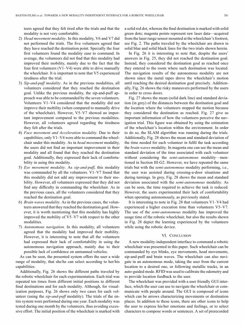
the robotic wheelchair for each experimentation. Each trial wasrepeated ten times from different initial positions to differentfinal destinations and for each modality. Although, for visual-ization purposes, Fig. 26 shows only two cases for each vol-unteer (using the sip-and-puff modality). The trials of the en-tire system were performed during one year. Each modality wastested during one month by the volunteers, thus avoiding exces-sive effort. The initial position of the wheelchair is marked with
a solid red dot, whereas the final destination is marked with solidgreen dots; magenta points represent raw laser data—acquiredfrom the laser range sensormounted at the wheelchair’s footrest,see Fig. 2. The paths traveled by the wheelchair are drawn insolid blue and solid black lines for the two trials shown herein.In Fig. 26 it is interesting to note that, despite the users’
answers in Fig. 25, they did not reached the destination goal.Instead, they considered the destination goal as reached oncethey entered to the room where such destination was located.The navigation results of the autonomous modality are notshown since the metal tapes drove the wheelchair’s motionuntil reaching the desired destination goal precisely. Addition-ally, Fig. 26 shows the risky maneuvers performed by the usersin order to cross doors.Fig. 27 shows the mean (solid dark line) and standard devia-
tion (in grey) of the distances between the destination goal andthe location where the volunteers stopped the motion becausethey considered the destination as reached. Fig. 27 give usimportant information of how the volunteers perceive the nav-igation trial. This figure was obtained by using the estimationof the wheelchair’s location within the environment. In orderto do so, the SLAM algorithm was running during the trials.Additionally, Fig. 28 shows the mean and standard deviation ofthe time needed for each volunteer in fulfil the task accordingthe brain wavesmodality. In magenta one can see the mean andstandard deviation of the time associated with each volunteerwithout considering the semi-autonomous modality—men-tioned in Section III-G2. However, we have repeated the sametrials but with the semi-autonomous modality performing, i.e.,the user was assisted during crossing-a-door situations andduring turnings. In grey, Fig. 28 shows the mean and standarddeviation associated with the semi-autonomous modality. Ascan be seen, the time required to achieve the task is reduced.However, the users experimented their lack of comfortabilitywhen operating autonomously, as previously stated.It is interesting to note in Fig. 28 that volunteers V1–V4 had
experienced a higher execution time than volunteers V5–V7.The use of the semi-autonomous modality has improved theusage time of the robotic wheelchair, but also the results shownin Fig. 28 depict the learning experienced by the volunteerswhile using the robotic device.
VI. CONCLUSION
A new modality-independent interface to command a roboticwheelchair was presented in this paper. Such wheelchair can becommanded by eye blinks, eye movements, head movements,sip-and-puff and brain waves. The wheelchair can also navi-gate in an autonomous mode, taking the user from the currentlocation to a desired one, or following metallic tracks, in anauto-guidedmode. RFIDwas used to calibrate the odometry andto provide location feedback to the user.The wheelchair was provided with a user friendly GUI inter-
face, which the user can use to navigate the wheelchair or com-municate with people around. The GUI is composed of iconswhich can be arrows characterizing movements or destinationplaces. In addition to these icons, there are other icons to helpthe user to express his/her emotions and feelings, or to selectcharacters to compose words or sentences. A set of prerecorded

582 IEEE TRANSACTIONS ON NEURAL SYSTEMS AND REHABILITATION ENGINEERING, VOL. 22, NO. 3, MAY 2014
Fig. 26. Navigation results for two trials of the sip-and-puff modality. Fig. 26(a)–(g) correspond to the navigation results of V1–V7, respectively.
Fig. 27. Mean and standard deviation of the distances between the navigationgoal and the position where the user considers that she/he has reached such adestination.
acoustic signals and a speaker onboard the wheelchair is pro-vided for this purpose.Kinematics and dynamic model-based control architectures
were used to control the wheelchair movement. The kinematic
Fig. 28. Mean—solid line—and standard deviation of the time required foreach user to complete the task with the brain waves modality according to botha nonautonomous and a semi-autonomous modality.
controller manages the wheelchair’s orientation and its linearand angular velocities, whereas the dynamic controller allowsfor generating smooth movements of the wheelchair. There isalso a supervisor that can receive inputs from the user onboardthe wheelchair, allowing the user to help the control system tomanage obstacles in a more efficient way.

BASTOS-FILHO et al.: TOWARDS A NEW MODALITY-INDEPENDENT INTERFACE FOR A ROBOTIC WHEELCHAIR 583
Several experiments were conducted with this robotic wheel-chair, using different command modalities. The wheelchair wasevaluated by healthy people and people with disabilities (adultand children), and got their approval, in addition to fill out aquestionnaire, with five questions regarding the modality per-formance and the user comfort. The associated statistical resultsand metric results obtained during the experimentation werealso shown.The next step involves only the BCI here described: it will
be extended to include the possibility of using motor imageryand signals from the Broca area of the brain. This option wouldallow the user to command intuitively the wheelchair with theintention of the movement of the left and right hand, and imag-ination of random words starting with the same letter. Prelim-inary experiments have been conducted using PSD and adap-tive autoregressive parameters as feature inputs to a classifierbased on support vector machine, and have shown encouragingpossibilities.
REFERENCES
[1] C. R. Cassemiro and C. G. Arce, “Visual communication by com-puter in amyotrophic lateral sclerosis,” Arquivos Brasileiros de Oftal-mologia, vol. 67, no. 2, pp. 295–300, 2004.
[2] C. F. Borges, “Dependency and die of the family mother: The helpingfrom family and community to take care of a pacient with amyotrophiclateral sclerosis,” Psicologia em Estudo, vol. 8, pp. 21–29, 2003.
[3] R. Barea, L. Boquete, M. Mazo, and E. Lopez, “Wheelchair guidancestrategies using EOG,” J. Intell. Robot. Syst., vol. 34, pp. 279–299,2002.
[4] R. C. Simpson, “Smart wheelchairs: A literature review,” J. Rehabil.Res. Develop., vol. 42, pp. 423–436, 2005.
[5] K. Tanaka, K.Matsunaga, and H.Wang, “Electroencephalogram-basedcontrol of an electric wheelchair,” IEEE Trans. Robot., vol. 21, no. 4,pp. 762–766, 2005.
[6] S. Ronnback, On methods for assistive mobile robots Dept. Comput.Sci. Electr. Eng., Lulea Univ. Technol., 2006 [Online]. Available:http://epubl.ltu.se
[7] A. Teymourian, T. Luth, A. Graser, T. Felzer, and R. Nordmann,“Braincontrolled finite state machine for wheelchair navigation,” inProc. 10th Int. ACM SIGACCESS Conf. Comput. Accessabil., 2008,pp. 257–258.
[8] C. Mandel, T. Luth, T. Laue, T. Rofer, A. Graser, and B.Krieg-Bruckner, “Navigating a smart wheelchair with a brain-com-puter interface interpreting steady-state visual evoked potentials,” inProc. IEEE/RSJ Int. Conf. Intell. Robots Syst., 2009, pp. 1118–1125.
[9] H. Soh and Y. Demiris, “Involving young children in the developmentof a safe, smart paediatric wheelchair,” presented at the ACM/IEEEHRI-2011 Pioneers Workshop, Lausanne, Switzerland, 2011.
[10] Y. Nam, Q. Zhao, and A. Cichocky, “Tongue-rudder: A glossokinetic-potential-based tongue-machine interface,” IEEE Trans. Biomed. Eng.,vol. 59, no. 1, pp. 290–299, Jan. 2012.
[11] C. Gao, T. Miller, J. Spletzer, I. Hoffman, and T. Panzarella, “Au-tonomous docking of a smart wheelchair for the automated transportand retrieval system (ATRS),” J. Field Robot., vol. 25, no. 4-5, pp.203–222, 2008.
[12] A. Kubler, B. Kotchoubey, J. Kaiser, J. R. Wolpaw, and N. Birbaumer,“Braincomputer communication: Unlocking the locked in,” Psychol.Bull., vol. 127, no. 3, pp. 358–375, 2001.
[13] F. A. A. Cheein, C. D. la Cruz, T. F. Bastos-Filho, and R. Carelli,“Navegacion autonoma asistida basada en SLAM para una silla deruedas robotizada en entornos restringidos,” Revista Iberoamericanade Autom. e Inform. Indust. RIAI, vol. 8, no. 2, pp. 81–92, 2011.
[14] T. F. Bastos, M. Sarcinelli-Filho, A. Ferreira, W. C. Celeste, R. L.Silva, V. R. Martins, D. C. Cavalieri, P. S. Filgueira, and I. B. Arantes,“Case study: Cognitive control of a robotic wheelchair,” in WearableRobots: Biomechatronic Exoskeletons. New York: Wiley, 2008, ch.9.
[15] F. A. A. Cheein, N. Lopez, C. Soria, F. L. Pereira, F. di Sciascio, andR. Carelli, “Slam algorithm applied to robotic assistance for navigationin unknown environments,” J. Neuroeng. Rehabil., vol. 7, no. 10, pp.1–15, 2010.
[16] E. Perez, C. Soria, M. Bortole, T. F. Bastos-Filho, and V. Mut, “Fusionof head angles to command a robotic wheelchair,” in Proc. Biosign.Robot. Better Safer Living, Vitoria, Brazil, 2010, pp. 1–6.
[17] C. D. la Cruz, T. F. Bastos-Filho, and R. Carelli, “Adaptive motioncontrol law of a robotic wheelchair,” Control Eng. Practice, vol. 19,pp. 113–125, 2011.
[18] P. F. S. Amaral, J. C. Garcia, T. F. Bastos-Filho, and M. Mazo, “Am-bient assisted route planner based on xml files with accessibility infor-mation,” in Proc. 6th IEEE Int. Symp. Intell. Signal Process., 2009, pp.147–152.
[19] S.-H. Chiu and J.-J. Liaw, “A proposed circle/circular arc detectionmethod using the modified randomized Hough transform,” J. Chin.Inst. Eng., vol. 29, no. 3, pp. 533–538, 2006.
[20] E. Schneider, K. Bartl, S. Bardins, T. Dera, G. Boening, and T. Brandt,“Eye movement driven head-mounted camera: It looks where the eyeslook,” in Proc. IEEE Int. Conf. Syst., Man Cybern., 2005, vol. 3, pp.2437–2442.
[21] G. Pires, U. Nunes, and M. Castelo-Branco, “Statistical spatial filteringfor a P300-based BCI: Tests in able-bodied, and patients with cerebralpalsy and amyotrophic lateral sclerosis,” J. Neurosci. Methods, vol.195, pp. 270–281, 2011.
[22] F. Cincotti, D. Mattia, F. Aloise, S. Bufalari, L. Astolfi, F. D. V. Fal-lani, A. Tocci, L. Bianchi, M. G. Marciani, S. Gao, J. Millan, and F.Babiloni, “High-resolution EEG techniques for brain-computer inter-face applications,” J. Neursci. Methods, vol. 167, pp. 31–42, 2008.
[23] F. Faradji, R. K. Ward, and G. E. Birch, “Plausibility assessment of a2-state self-paced mental task-based BCI using the no-control perfor-mance analysis,” J. Neursci. Methods, vol. 180, pp. 330–339, 2009.
[24] F.-B. Vialatte, M. Maurice, J. Dauwels, and A. Cichocki, “Steady-statevisually evoked potentials: Focus on essential paradigms and futureperspectives,” Prog. Neurobiol., vol. 90, pp. 418–438, 2010.
[25] C. Ming and G. Shangkai, “An EEG -based cursor control system,” inProc. 1st Joint BMES/EMBS Conf., 1999, vol. 1, p. 699.
[26] B.Y.Wang, X.Gao, B.Hong, C. Jia, and S.Gao, “Brain computer inter-faces based on visual evoked potentials—Feasibility of practical systemdesigns,” IEEEEng.Med. Biol. Mag., pp. 64–71, Sep./Oct. 2008.
[27] A. Teymourian, T. Lüth, A. Gräser, T. Felzer, and R. Nordmann,“Brain-controlled finite state machine for wheelchair navigation,” inProc. 10th Int. ACM SIGACCESS Conf. Comput. Accessibil., 2008,pp. 257–258.
[28] C. Mandel, T. Luth, T. Laue, T. Rofer, A. Gräser, and B.Krieg-Brückner, “Navigating a smart wheelchair with a brain-com-puter interface interpreting steady-state visual evoked potentials,” inProc. IEEE/RSJ Int. Conf. Intell. Robots Syst., 2009, pp. 1118–1125.
[29] A. M. F. L. M. de Sá, H. C. Thiengo, I. S. Antunes, and D. M. Simpson,“Assessing time- and phase-locked changes in the EEG during sensorystimulation by means of spectral techniques,” in Proc. IFMBE, 2009,vol. 25, pp. 2136–2139.
[30] F. A. Cheein, R. Carelli, W. C. Celeste, T. F. Bastos, and F. di Sciascio,“Maps managing interface design for a mobile robot navigation,” in J.Phys. Conf. Ser., 2007, vol. 90, p. 012088.
[31] S. L. G. Ippoliti and L. Jetto, “Localization of mobile robots: Develop-ment and comparative evaluation of algorithms based on odometric andinertial sensors,” J. Field Robot., vol. 22, no. 12, pp. 725–735, 2005.
[32] F. A. A. Cheein and R. Carelli, “Analysis of different features selectioncriteria based on a covariance convergence perspective for a SLAMalgorithm,” Sensors (Basel), vol. 11, no. 1, pp. 62–89, 2011.
[33] F. A. A. Cheein, C. De la Cruz, T. F. Bastos-Filho, and R. Carelli,“Slam-based cross-a-door solution approach for a robotic wheelchair,”Int. J. Adv. Robot. Syst., vol. 6, no. 3, pp. 239–248, 2009.
[34] E. C. D. Kulic, “Safe planning for human-robot interaction,” J. FieldRobot., vol. 22, no. 7, pp. 383–396, 2005.
[35] F. Wolfe, “A brief clinical health assessment instrument: Clinhaq,”Arthritis Rheum., vol. 32, p. C49, 1989.
Teodiano Freire Bastos-Filho graduated in elec-trical engineering from the Universidade Federaldo Espírito Santo, Vitória, Brazil, in 1987, andreceived the Ph.D. degree in physical sciences fromthe Universidad Complutense de Madrid, Madrid,Spain, in 1994.He is with the Department of Electrical Engi-
neering, Universidade Federal do Espírito Santo,Vitória, Brazil, and with the Brazilian NationalCouncil for Scientific and Technological Devel-opment (CNPq). His research interests are signal
processing, rehabilitation robotics and assistive technologies.

584 IEEE TRANSACTIONS ON NEURAL SYSTEMS AND REHABILITATION ENGINEERING, VOL. 22, NO. 3, MAY 2014
Fernando Auat Cheein (M’12) received the B.Sc.degree in electronic engineering from the NationalUniversity of Tucuman, Tucuman, Argentina, in2002, and the Ph.D. degree in control systemsengineering from the National University of SanJuan, San Juan, Argentina, in 2009.From 2009 to 2011, he was involved in Argen-
tinean projects of robotics applied to agriculture. Cur-rently, he is with the Department of Electronic Engi-neering, Universidad Tecnica Federico Santa Maria,Valparaiso, Chile, working in projects related to un-
manned robots in olive groves. His research interests also include autonomousSLAM and path planning.
Sandra Mara Torres Müller received the B.Sc.,M.Sc. and Ph.D. degrees in electrical engineeringfrom the Federal University of Espírito Santo,Vitória, ES, Brazil, in 2003, 2006, and 2012, respec-tively.She is currently with the Department of Computer
and Electronics of the Federal University of EspíritoSanto, São Mateus, ES, Brazil. Her research interestsare in signal processing, biological signal processing,pattern recognition, and brain–computer interfaces.
Wanderley Cardoso Celeste received the B.Sc.,M.Sc., and Ph.D. degrees in electrical engineeringfrom the Federal University of Espírito Santo,Vitória, ES, Brazil, in 2002, 2005, and 2009, respec-tively.He is currently with the Department of Computer
and Electronics of the Federal University of EspíritoSanto, São Mateus, ES, Brazil, where he is a perma-nent member of the Graduate Program on Energy.His research interests are automation and control sys-tems.
Celso de la Cruz received the B.Sc. degree in me-chanical engineering from the Universidad Nacionaldel Centro, Huancayo, Peru, in 1996, the M.Sc. de-gree in control and automation engineering from thePontificia Universidad Católica, Lima, Peru, 1999,and the Ph.D. degree in control systems engineeringfrom the National University of San Juan, San Juan,Argentina, in 2006.His research interests are mechatronics, with em-
phasis in control, and control of multi-robot forma-tions.
Daniel Cruz Cavalieri received the B.Sc. degree inelectrical engineering from the Federal University ofViçosa, Viçosa, MG, Brazil, in 2005, and the M.Sc.and Ph.D. degrees in electrical engineering from theFederal University of Espírito Santo, Vitória, ES,Brazil, in 2008 and 2013, respectively.His research interests are natural language pro-
cessing, human–machine interfaces, and assistivetechnologies.
Mário Sarcinelli-Filho received the B.Sc. degreefrom Federal University of Espírito Santo, Vitória,ES, Brazil, in 1979, and the M.Sc. and Ph.D. degreesfrom Federal University of Rio de Janeiro, Rio deJaneiro, Brazil, in 1983 and 1990, respectively, allin electrical engineering.He is with the Department of Electrical En-
gineering, Federal University of Espírito Santo,and the Brazilian National Council for Scientificand Technological Development (CNPq). His re-search interests are signal and image processing,
brain–computer interfaces, mobile robotics, coordinated control of mobilerobots, and unmanned aerial vehicles.
Paulo Faria Santos Amaral received the B.Sc.degree in electronic engineer from the TechnologicalInstitute of Aeronautics, São José dos Campos,SP, Brazil, in 1976, the M.Sc. degree in electronicengineering from the National Institute of SpacialResearch, Brazil, São José dos Campos, SP, Brazil, in1979, and the Ph.D. degree in electrical engineeringfrom the University of São Paulo, São Paulo, SP,Brazil, in 1985.He has retired from the Federal University of Es-
pírito Santo, Brazil, where he was an Associate Pro-fessor at the Department of Electrical Engineering.
Elisa Perez graduated in biomedical engineering, in2004, from the National University of San Juan, SanJuan, Argentina, where she received the Ph.D. degreein control systems engineering, in 2010.She is currently an Associate Professor at the
National University of San Juan, San Juan, Ar-gentina. Her research interests are image processing,human–computer interfaces, and control of roboticwheelchairs.
Carlos Miguel Soria graduated in electrical engi-neering from the National University of Tucuman,Tucuman, Argentina, in 1996, and the M.Sc. andPh.D. degrees in control systems engineering fromthe National University of San Juan, San Juan,Argentina, in 2000 and 2005, respectively.He is presently Associate Professor at the National
University of San Juan and Assistant Researcher ofthe National Council for Scientific and Technical Re-search (CONICET, Argentina). His research interestsare control of manipulators and mobile robots, com-
puter vision, and sensorial integration.
Ricardo Carelli (M’76–SM’98) was born in SanJuan, Argentina. He graduated in engineering fromthe National University of San Juan, San Juan, Ar-gentina, and received the Ph.D. degree in electricalengineering from the National University of Mexico,Mexico City, Mexico.He is full Professor at the National University of
San Juan, where he is Director of the Instituto deAutomática, and Senior Researcher of the NationalCouncil for Scientific and Technical Research(CONICET, Argentina). His research interests are
on robotics, manufacturing systems, adaptive control and artificial intelligenceapplied to automatic control.