ieee transactions on computer-aided design … · electronic system-level synthesis methodologies...
TRANSCRIPT

IEEE TRANSACTIONS ON COMPUTER-AIDED DESIGN OF INTEGRATED CIRCUITS AND SYSTEMS 1
Electronic System-Level Synthesis MethodologiesAndreas Gerstlauer, Member, IEEE, Christian Haubelt, Member, IEEE, Andy D. Pimentel, Senior Member, IEEE,
Todor Stefanov, Member, IEEE, Daniel D. Gajski, Fellow, IEEE, and Jurgen Teich, Senior Member, IEEE
Abstract—With ever increasing system complexities, all majorsemiconductor roadmaps have identified the need for moving tohigher levels of abstraction in order to increase productivity inelectronic system design. Most recently, many approaches andtools that claim to realize and support a design process at theso called Electronic System Level (ESL) have emerged. However,faced with the vast complexity challenges, in most cases at bestonly partial solutions are available.
In this paper, we develop and propose a novel classification forESL synthesis tools, and we will present six different academicapproaches in this context. Based on these observations, we canidentify such common principles and needs as they are leadingtowards and are ultimately required for a true ESL synthesissolution, covering the whole design process from specificationto implementation for complete systems across hardware andsoftware boundaries.
Index Terms—Electronic System Level (ESL), synthesis,methodology
I. INTRODUCTION
IN order to increase design productivity, raising the levelof abstraction to the Electronic System Level (ESL) seems
mandatory. Surely, this must be accompanied by new EDAtools [1]. Many approaches exist today that claim to provideESL solutions. In [2], Densmore et al. define an ESL clas-sification framework that focuses on individual design tasksby reviewing more than 90 different point tools. Many ofthese tools are devoted to modeling purposes (functional orplatform) only. Other tools provide synthesis functionalityby either software code generation or C-to-RTL high-levelsynthesis. However, true ESL synthesis tools show the abilityto combine design tasks under a complete flow that cangenerate systems across hardware and software boundariesfrom an algorithmic specification. In this paper, we thereforeaim to provide an extended classification focusing on suchcomplete ESL flows on top of individual point solutions.
Typically, ESL synthesis tools are domain specific andrely on powerful computational models [3] for descriptionof desired functional and non-functional requirements at the
Manuscript received February 25, 2009; revised June 8, 2009.Andreas Gerstlauer is with the Department of Electrical and
Computer Engineering, The University of Texas at Austin. E-mail:[email protected].
Christian Haubelt and Jurgen Teich are with the Department of Com-puter Science, University of Erlangen-Nuremberg. E-mail: {haubelt,teich}@cs.fau.de.
Andy D. Pimentel is with the Informatics Institute, University of Amster-dam. E-mail: [email protected].
Todor Stefanov is with the Leiden Institute of Advanced Computer Science,Leiden University. E-mail: [email protected].
Daniel. D. Gajski is with the Center for Embedded Computer Systems,University of California, Irvine, CA. E-mail: [email protected].
Copyright c!2009 IEEE. Personal use of this material is permitted. How-ever, permission to use this material for any other purposes must be obtainedfrom the IEEE by sending an email to [email protected].
input of the synthesis flow. Such well-defined, rich inputmodels are a prerequisite for later analysis and optimization.Typical computational models in digital system design areprocess networks, dataflow models or state machines. On theother hand, implementation platforms for such systems areoften heterogeneous or homogeneous Multi-Processor System-on-Chip (MPSoC) solutions [4]. The complexity introducedby both, input computational model and target implementa-tion platform, results in a complex synthesis step includinghardware/software partitioning, embedded software generationand hardware accelerator synthesis. Beside this, at ESL, thenumber of design decisions, especially in communicationsynthesis, is compelling in contrast to lower abstraction levels.Even more so, due to the increasing number of processorsin MPSoCs, the impact of the quality in computation andcommunication synthesis is ever increasing.
In this paper, we aim to provide an analysis and compar-ative overview of the state-of-the-art, current directions andfuture needs in ESL synthesis methodologies and tools. Afteridentifying common principles based on our observations, wedevelop and propose a general framework for classificationand eventually comparison of different tools in Section II. InSection III, we then present in detail a representative selectionof three ESL approaches developed in our groups. To providea more complete overview, Section IV briefly discusses threerelated academic approaches. After introducing all six tools,we follow with a comparison and discussion of future researchdirections based on our classification criteria in Section V.Finally, the paper concludes with a summary in Section VI.
II. ELECTRONIC SYSTEM DESIGN
In this section, we will identify common principles inexisting ESL synthesis methodologies and develop a novelclassification for such approaches. Later, this will enable acomparison of different methodologies. Furthermore, based onsuch observations, synergies between different approaches canbe explored and corresponding interfaces between differenttools can be defined and established in the future.
A. Design FlowBefore deriving a model for ESL synthesis, we start by
defining the system design process in general. As nearly allESL synthesis methodologies follow a top-down approach,a definition of the design process should support this view.Furthermore, it should show the concurrent design of hardwareand software and required synthesis steps. A visualization ofthis is given by the double roof model [5] shown in Figure 1.
The double roof model defines the ideal top-down designprocess for embedded hardware/software systems. One side of

IEEE TRANSACTIONS ON COMPUTER-AIDED DESIGN OF INTEGRATED CIRCUITS AND SYSTEMS 2
......uArch
ISA
GateSoftware Hardware
Architecture
RTL
Instruction Logic
System
ComponentTask
Implementation
Specification
Fig. 1. Electronic system design flow.
the roof corresponds to the software design process whereasthe other side corresponds to the hardware design process.Each side is organized in different abstraction levels, e.g., taskand instruction levels or component and logic levels for thesoftware or hardware design processes, respectively. There isone common level of abstraction, the Electronic System Level(ESL), at which we can not distinguish between hardware andsoftware. At each level, in a synthesis step (vertical arrow), aspecification is transformed into an implementation. Horizontalarrows indicate the step of passing models of individualelements in the implementation directly to the next lower levelof abstraction as specifications at its input.
The double roof model can be seen as extending the Y-chart [6] by an explicit separation of software and hardwaredesign. Furthermore, for simplicity we do not include a thirdlayout roof representing a physical view of the design. Note,however, that layout information, while traditionally being ofminor importance, is increasingly employed even at the systemlevel, e.g., through early floorplanning, to account for spatialeffects such as activity hot spots [7], wiring capacitances ordistance-dependent latencies [8].
The design process represented by the double roof modelstarts with a ESL specification given by a behavioral modelthat is often some kind of network of processes communicatingvia channels. Additionally, a set of mapping constraints andimplementation constraints (maximum area, minimal through-put, etc.) is given. The platform model at ESL is typically astructural model consisting of architectural components suchas processors, busses, memories, and hardware accelerators.The task of ESL synthesis is then the process of selecting anappropriate platform architecture, determining a mapping ofthe behavioral model onto that architecture, and generating acorresponding implementation of the behavior running on theplatform. The result is a refined model containing all designdecisions and quality metrics, such as throughput, latency orarea. If selected, components of this refined model are thenused as input to the design process at lower abstraction levels,where each hardware or software processor in the systemarchitecture is further implemented separately.
Synthesis at lower levels is a similar process in which abehavioral or functional specification is refined down into astructural implementation. However, depending on the abstrac-
tion level, the granularity of objects handled during synthesisdiffers and some tasks might be more important than others.For instance, at the task level on the software side, communi-cating processes/threads bound to the same processor must betranslated into the instruction set architecture (ISA) of the pro-cessor, targeted towards and running on top of an off-the-shelfreal-time operating system (RTOS) or a custom-generatedruntime environment. This software task synthesis step istypically performed using a (cross-)compiler and linker toolchain for the selected processor and RTOS. At the instructionlevel, the instruction set of programmable processors is thenrealized in hardware by implementing the underlying micro-architecture (uArch). This step results in a structural modelof the processor’s datapath organization, usually specified asa register-transfer level (RTL) description.
On the other hand, at the component level on the hardwareside, processes selected to be implemented as hardware accel-erators are synthesized down to an RTL description in the formof controller state machines that drive a datapath consistingof functional units, register files, memories and interconnect.This refinement step is commonly referred to as behavioral orhigh-level synthesis. Today, there are several tools availableto perform such high-level synthesis automatically [9], [10].Finally, at the logic level, the granularity of the objectsconsidered during logic synthesis then corresponds to Booleanformulae implemented by logic gates and flip flops.
An important observation that can be made from Figure 1 isthat at the RT level, hardware and software worlds unite again,both feeding into (traditional) logic design processes downto the final manufacturing output. Also, we note that a top-down ESL design process relies on the availability of designflows at the component or task (and eventually logic andinstruction) levels to feed into on the hardware and softwareside, respectively. Lower level flows can be supplied either inthe form of corresponding synthesis tools or by providing pre-designed intellectual property (IP) components to be pluggedinto the system architecture.
B. Synthesis ProcessBefore identifying the main tasks in ESL synthesis, we
first develop a general synthesis framework applicable at alllevels. As discussed in the previous section, during synthesis aspecification is generally transformed into an implementation.This abstract view can be further refined into an X-chart asshown in Figure 2. With this refinement, we can start to defineterms essential in the context of synthesis.
A specification is composed of a behavioral model andconstraints. The behavioral model represents the intendedfunctionality of the system. Its expressibility and analyzabilitycan be declared by its underlying Model of Computation(MoC) [3]. The behavioral model is often written in someprogramming language (e.g., C, C++ or JAVA), system-leveldescription language (e.g., SpecC or SystemC), or a hardwaredescription language (such as Verilog or VHDL).
The constraints often include an implicit or explicit platformmodel that describes an architecture template, e.g., availableresources, their capabilities (or services) and their intercon-nections. Analogous to the classification of behavioral models

IEEE TRANSACTIONS ON COMPUTER-AIDED DESIGN OF INTEGRATED CIRCUITS AND SYSTEMS 3
Constraints
QualityNumbers
Behavior
RefinementMakingDecision
Synthesis
Structure
Specification
Implementation
Fig. 2. Synthesis process.
into MoCs, specific ways of describing architecture templatescan be generalized into Models of Architecture (MoA) [11].Similar to the concept of MoCs, a MoA describes the char-acteristics underlying a class of platform models in orderto evaluate richness of supported target architectures at theinput of a synthesis tool. ESL architecture templates canbe coarsely subdivided based on their processing, memoryand communication hierarchy. On the processing side, ex-amples include single-processor systems, hardware/softwareprocessor/co-processor systems, and homogeneous, symmet-ric or heterogeneous, asymmetric multi-processor/multi-coresystems (MPSoCs) [4]1. Memory-wise we can distinguishshared versus distributed memory architectures. Finally, com-munication architectures can be loosely grouped into shared,bus-based or Network-on-Chip (NoC) approaches. Beside thearchitecture template, constraints typically contain mappingrestrictions and additional constraints on non-functional prop-erties like maximum response time or minimal throughput.
The synthesis step then transforms a specification into animplementation. An implementation consists of a structuralmodel and quality numbers. The structural model is a re-fined model from the behavioral model under the constraintsgiven in the specification. In addition to the implementation-independent information contained in the behavioral model,the structural model holds information about the realizationof design decisions from the previous synthesis step, i.e.,mapping of the behavioral model onto an architecture tem-plate. As such, a structural model is a representation of theresulting architecture as a composition of components thatare internally described in the form of behavioral modelsfor input to the next synthesis step. On top of a well-defined combination of MoCs for component-internal behav-ior and functional semantics, we can hence introduce theterm Model of Structure (MoS) for separate classification ofsuch implementation representations and their architectural orstructural semantics. Again, a MoS allows characterization of
1While details of supported architecture features and restrictions, as defined,e.g., by tool database formats, can differ significantly, we limit discussionsand comparisons to such high-level MoA classifications in this paper.
the underlying abstracted semantics of a class of structuralmodels independent of their syntax. Hence, MoSs can beused to compare expressibility and analyzability of specificimplementation representations as realized by different tools.For example, at many levels a netlist concept is used withsemantics limited to describing component connectivity. Atthe system level, pin-accurate models (PAMs) combine anetlist with bus-functional component models. Furthermore,transaction-level modeling (TLM) concepts and techniques areemployed to abstract away from pins and wires2. Similar tobehavioral models, structural models are often represented ina programming language, system-level description language(SLDL) or hardware description language (HDL).
Quality numbers are estimated values for different imple-mentation properties, e.g., throughput, latency, response time,area and power consumption. In order to get such estimates,synthesis tools often use so called performance models insteadof implementing each design option3. Performance modelsrepresent the contributions of individual elements to overalldesign quality in a given implementation. Basic numbersare composed based on specific semantics, e.g., in termsof annotation granularity or worst/average/best case assump-tions, such that overall quality estimates can be obtained,e.g., through simulation or static analysis. To distinguish andclassify representations of quality numbers across differentinstances and implementations of performance models, weintroduce the concept of an underlying Model of Performance(MoP). A MoP thereby refers to the overall accuracy andgranularity in time and space. Generalizing from the detaileddefinitions of specific performance models, such as timing,power or cost/area models, a MoP can be used to judge theaccuracy of the quality numbers and the computational effortto get them. Examples of simulation-based MoPs for differentclasses of timing granularity are Cycle Accurate PerformanceModels (CAPMs), Instruction Set Accurate Performance Mod-els (ISAPMs) or Task Accurate Performance Models (TAPMs)[12]. Quality numbers are often used as objective values duringdesign space exploration when identifying the set of optimalor near-optimal implementations.
Given a specification, the task of synthesis then generates animplementation from the specification by decision making andrefinement (Figure 2). At any level, synthesis is a process ofdetermining the order or mapping of elements in the behavioralmodel in space and time, i.e., the where and when of theirrealization. Decision making is hence the task of computingan allocation of resources available in the platform model,a spatial binding of objects in the behavioral model ontothese allocated resources, and a temporal scheduling to resolveresource contention of objects in the behavioral model boundto the same resource.
Refinement is the task of incorporating the made decisionsinto the behavioral model resulting in a structural model, asdiscussed above. Moreover, with these decisions, a qualityassessment of the resulting implementation can be done. The
2Again, many definitions of specific TLM variants exist but for simplicitywe limit discussions in this paper to a general classification.
3We use the term “performance” in the general sense to refer to anymeasured property.

IEEE TRANSACTIONS ON COMPUTER-AIDED DESIGN OF INTEGRATED CIRCUITS AND SYSTEMS 4
result of this assessment are the quality numbers.Finally, in order to optimize an implementation, a Design
Space Exploration (DSE) should be performed. As designspace exploration is a multi-objective optimization problem,in general, we will identify a set of optimal implementationsinstead of a single optimal implementation. For this purpose,the quality numbers provided by the MoP are used. In thispaper, we define DSE being the multi-objective optimizationproblem of the synthesis task. In other words, decision makingis the task of calculating a single feasible allocation, binding,and scheduling instance, whereas DSE is the process of findingoptimal design points.
In summary, the X-chart shown in Figure 2 combines twoaspects: synthesis (left output) and quality assessment (rightoutput). For both aspects, corresponding so called Y-chartsexist in the literature: the synthesis aspect was presented andlater refined into a first system design methodology by Gajskiet al. in [6] and [13], respectively, while the quality assessmentaspect was proposed by Kienhuis et al. in [14].
With the above discussion, first classification criteria forsynthesis tools can be derived:(1) Expressibility and analyzability of the specification:
(1.1) The MoC of the behavioral model. As in generalexpressibility can be traded against analyzability,the MoC has a huge influence on the automationcapabilities of a synthesis tool.
(1.2) The MoA of the platform model given in the con-straints. The MoA as used for refinement determinesthe classes of target implementations supported by aparticular tool.
(2) Representations of the implementation:(2.1) The MoS of the structural model. As structural
models are often used for validation and virtualprototyping, the MoS can have a large influence onissues such as simulation performance, observabilityand accuracy.
(2.2) The MoP of the performance model given throughthe quality numbers. Performance models are em-ployed for quality assessment and thus, the MoP haslarge impact on the synthesis quality and estimationaccuracy.
As DSE can be performed manually or automatically, anadditional classification criteria to be considered is:(3) Is DSE automated, i.e., does a methodology integrate
some multi-objective optimization strategy for decisionmaking?
C. ESL Synthesis
In general, both decision making and refinement, can beautomated. However, ESL synthesis is a more complex taskcompared to synthesis at lower levels of abstractions. Atany level, tasks to be performed during decision makingand supported during refinement are computing and realizingan allocation, binding, and scheduling. At ESL, however,these three steps have to be performed for a design spacewhich is at its largest, and are required for both computations
and communications in the behavioral model. Furthermore,compared to lower levels where refinement is often reducedto producing a simple netlist, generating an implementationof system-level computation and communication decisions isa non-trivial task that requires significant coding effort.
In computation synthesis, processing elements (PEs), e.g.,processors, hardware accelerators, memories and IP coreshave to be allocated from the platform model. The resultingallocation has to guarantee that at least each process fromthe behavioral model can be bound to an allocated processingelement. A further task in computation synthesis is processbinding where each process has to be bound to an allocatedprocessing element. A third task in computation synthesis isprocess scheduling, i.e., a partial/total order is imposed on theprocesses using a static or dynamic scheduling strategy.
In communication synthesis, communication elements (CEs)including busses, point-to-point-connections, Networks-on-Chip (NoCs), bus bridges and transducers have to be allocated.Here, the resulting topology must guarantee that each applica-tion communication channel can be bound to an ordered set ofarchitectural communication media, and that channel accesses(transactions) can be routed on the communication elements. Asecond task is application channel binding to route application-level communication channels over the allocated architecturalnetwork topology. Finally, transactions must be scheduled onthe communication media using static time division access(TDMA) or dynamic, centralized or distributed arbitration. Asis the case in process scheduling, transaction scheduling canresult in static, dynamic, or quasi-static schedules.
It should be clearly stated that computation synthesis andcommunication synthesis are by no means independent tasks.Hence, an oversimplified synthesis method might result ininfeasible or suboptimal solutions only. Many approaches areheavily biased towards either computation synthesis (e.g., [15],[16]) or communication synthesis (e.g., [17], [18], [19]), as-suming the counterpart to be done by a different tool. In orderto ensure feasibility and optimality, however, an ESL synthesismethodology should support computation and communicationsynthesis with all their respective subtasks.
As ESL synthesis with its subtasks can be automatedin decision making and/or refinement, we now can defineadditional classification criteria for ESL synthesis tools:(4) Is decision making automated and, if yes, which tasks are
automated?(4.1) Are computation design decisions computed auto-
matically?(4.2) Are communication design decisions computed au-
tomatically?(5) Is refinement automated and, if yes, which tasks are
performed automatically?(5.1) Is computation refinement automatic?(5.2) Is communication refinement automatic?
With the criteria 1-5, we can classify and compare ESL syn-thesis tools. In the following sections, we will discuss six ESLsynthesis approaches. For all six approaches, we will evaluatetheir methodologies with respect to these classification criteria.In addition, three ESL synthesis approaches developed in our

IEEE TRANSACTIONS ON COMPUTER-AIDED DESIGN OF INTEGRATED CIRCUITS AND SYSTEMS 5
own groups will be elaborated on in some more detail.
III. A THREESOME OF ESL METHODOLOGIES
In this section, we will present three synthesis approachesout of the authors’ own research. In addition to classificationof underlying methodologies based on previously introducedcriteria, this includes details of design steps and experiencesresulting from our development and experimental work.
A. DaedalusDaedalus provides an integrated and highly-automated
framework for system-level architectural exploration, system-level synthesis, programming, and prototyping of heteroge-neous Multi-Processor System-on-a-Chip (MPSoC) platforms[20], [21]. The Daedalus design flow, which is depicted inFigure 3, leads the designer in a number of steps from asequential application (i.e., behavioral specification) to an MP-SoC system implementation on an FPGA with a parallelizedversion of the application mapped onto it. This means thatDaedalus includes or interfaces with component- and task-level back-end synthesis processes to produce an MPSoCimplementation at the RTL and ISA levels for hardwarecomponents and software processes, respectively. Since theentire design trajectory can be traversed in only a matter ofhours, it offers great potentials for quickly experimenting withdifferent MPSoCs and exploring a variety of design optionsduring the early stages of design.
1) Scope of Methodology: A key assumption for theDaedalus framework is that it considers only dataflow domi-nated applications in the realm of multimedia, imaging, andsignal processing, that naturally contain tasks communicatingvia streams of data. Such applications are conveniently mod-eled by means of the Kahn Process Network (KPN) MoC [22].The KPN MoC we use is a dataflow network of concurrentprocesses that communicate data in a point-to-point fashionover bounded FIFO channels, using blocking read/write on anempty/full FIFO as synchronization mechanism. The KPNsthat Daedalus operates upon can be manually derived orautomatically generated. In the latter case, behavioral inputspecifications are sequential C programs. But to allow forautomatic translation into a KPN, these C applications need tobe specified as so called Static Affine Nested Loop Programs(SANLPs) [23], which is an important class of programs in,e.g., the scientific and multimedia application domains.
In terms of target MoA, Daedalus considers MPSoC plat-forms in which both programmable processors and dedicatedhardwired IP cores are used as processing components. Theycommunicate data only through distributed memory units.Each memory unit can be organized as one or several FIFOs.The data communication and synchronization between proces-sors are realized by blocking read and write primitives. Suchplatforms match and support the KPN operational semanticsvery well, thereby achieving high performance when KPNsare executed on the platforms. Also, directly supporting theoperational semantics of a KPN, i.e., the blocking mechanism,in the target platforms allows the processors to be self-scheduled. This means that there is no need for a globalscheduler in the platforms.
FPGA
P
PµValid
atio
n / C
alib
ratio
n
specification
specification
specificationSystem−level
Gate−levelµ
Pµ
Mem
HW IP
MemMP−SoC
Interconnect, e.g.,P2P, Xbar, or Bus
RTLAuxiliary
Platform spec.in XML
Sequentialprogram in C
IP cores
Models
in VHDL
Network in XML
High−level
Platform
Kahn ProcessIP Library
System−level architectural exploration:
Models
code forCprocessors
Sesame
ESPAM
Xilinx Platform Studio
netlist
Automated system−level synthesis:
files
in XML
RTL
KPNgen
RTL synthesis: commercial tool, e.g.
Mapping spec. Parallelization
Fig. 3. The Daedalus ESL design flow.
Daedalus architectures are constructed from a library of pre-defined and pre-verified IP components. These componentsinclude a variety of programmable processors, dedicated hard-wired IP cores, memories, and interconnects, thereby allowingthe implementation of a wide range of heterogeneous MPSoCplatforms. So, this means that Daedalus aims at composableMPSoC design, in which MPSoCs are strictly composed ofIP library components. Figure 4(b) shows a typical exampleof a Daedalus MPSoC platform. Daedalus produces platformsin the form of synthesizable VHDL (i.e., a netlist MoS)together with the C code for KPN processes that are mappedonto programmable processors. As a consequence, Daedalusdesigns can be readily mapped on an FPGA for prototyping.
Daedalus supports the mapping of multiple KPN processesonto a single processor. However, it tries to avoid using amulti-threading operating system (MTOS) to execute multipleprocesses on a single processor in order to avoid executionoverheads due to context switching. If possible, Daedalus per-forms compile-time scheduling of the processes that executeon a single processor and thus generates program code for agiven processor that does not require an MTOS. However, iffinding a compile-time schedule is not possible because of thedynamic (data-dependent) nature of an application, Daedalususes a very lightweight MTOS to perform runtime schedulingof the processes that execute on a single processor.
The above design process is guided by automated DSE,which uses a MoP that combines a TAPM and an ISAPM toevaluate design instances. Moreover, Daedalus’ computationsynthesis trajectory is fully automated, while its communica-tion synthesis is semi-automatic as it uses communication IPcomponents which may need to be customized by hand.
2) Daedalus’ Design Steps: As illustrated in Figure 3,Daedalus’ design flow consists of three key steps, whichare implemented by the KPNgen, Sesame and ESPAM toolsrespectively. KPNgen [23] allows for automatically convertinga sequential (SANLP) behavioral specification written in C,into a concurrent KPN [22] specification. By means of au-tomated source-level transformations, KPNgen is also capableof producing different input-output equivalent KPNs, in whichfor example the amount of concurrency can be varied. Suchtransformations enable behavioral-level DSE.

IEEE TRANSACTIONS ON COMPUTER-AIDED DESIGN OF INTEGRATED CIRCUITS AND SYSTEMS 6
name = "CB" type = "Crossbar"><network
name = "IO4"/><portname = "IO3"/><portname = "IO2"/><port
<port name = "IO1"/>
1
10
20
15
5
25
30 </platform>
name ="myPlatform">
</network>
</link>
</link>
<link
</link>
<link name = "BUS4"/></link>
<resource name = "IO3" /><resource name = "IO1" />
<link />name = "BUS3"
<resource name = "IO2" />name = "IO1" />
/>name = "BUS2"
<resource name = "IO1" />name = "uP1"<resource name = "IO1" />
<link name = "BUS1"/>
<resource
<processor </processor>
<processor </processor>
<platform
<processor </processor>name = "IO1"/>>
name = "uP1" > name = "IO1"/>name = "IO1"/>
<port> <port
<port<processor <port name = "IO1"/> </processor>
name = "HIP2"name = "HIP1"
> name = "uP2"
name = "CB"
name = "HIP2"name = "CB"
name = "HIP1"<portname = "CB"
<port<port
<port<port
<port
<resource name = "IO4" /><resource name = "IO1" /><port
<portname = "uP2"name = "CB"
(a) Platform specification
uP − Microprocessor
MEM− Program and Data MemoryMC − Memory Controller
CC − Communication ControllerCM − Communication Memory
− CrossbarCB
HIP − Dedicated Hardwired IP Core
CB
CC3
MEM1
MC1
CM1 CM3
uP1
CC2
CM2
CC4
CM4
MC4
Legend:
HIP1
HIP2 uP2
MEM2
CC1
(b) Elaborate platform
Fig. 4. Example of a Daedalus MPSoC platform.
The generated or handcrafted KPNs are subsequently usedby the Sesame modeling and simulation environment [24]to perform system-level architectural DSE. To this end,Sesame uses (high-level) architecture model components fromDaedalus’ IP component library (see the left part of Figure 3).Sesame allows for quickly evaluating the performance ofdifferent design decisions in terms of target platform archi-tectures (i.e., resource allocation), binding of KPN processesto architecture resources, and scheduling policies. Here, abalanced trade-off has been made between simulation accuracyand performance, allowing for extremely fast TAPM-levelsimulations while still yielding trustworthy estimations. But,on the other hand, Sesame also supports a gradual refinementof its architecture performance models to increase accuracy.This can, for example, be realized by gradually incorporat-ing (external) lower-level simulation models, such as cycle-accurate instruction set simulators, into Sesame’s high-levelarchitecture performance models.
Besides exhaustive simulative DSE to study certain focusedregions of a design space, Sesame also supports heuristicsearch methods, such as genetic algorithms, to steer DSE inlarger design spaces. Moreover, it includes an additional designspace pruning step, which is based on analytical models andtakes place before DSE to trim the design space that needs tobe studied using simulation.
Sesame’s DSE results in a set of promising candidate systemdesigns, each of which are described using a high-level, XML-based platform description (illustrated in Figure 4(a)) andprocess binding description. These high-level descriptions,together with the (behavioral) KPN description, act as input tothe ESPAM tool [25]. This tool subsequently uses RTL ver-sions of the components from the IP library to automaticallygenerate synthesizable VHDL that implements the candidateMPSoC platform architecture. In addition, it also generatesthe C code for those KPN processes that are mapped ontoprogrammable cores. Using commercial synthesis tools andcompilers, this implementation can be readily mapped ontoan FPGA for prototyping. Such prototyping also allows forcalibrating and validating Sesame’s system-level models, andthus improves the trustworthiness of these models.
3) Daedalus Experiences: Typically, Daedalus can be de-ployed in situations where rapid quantitative insight is neededinto a variety of different design options during the very earlystages of design. For example, Daedalus has been recentlyused in a case study together with the Dutch SME ChessB.V. [21] for studying different MPSoC implementations forimage compression of very high resolution (medical) images.Hence, Daedalus was used for design space exploration,both at the level of simulations and prototypes, in order torapidly gain detailed insight on the system performance. Thestudied MPSoCs exploit concurrency at three levels: multipleencoders are operating on different image tiles in parallel,each encoder exploits task parallelism in a pipelined fashion(i.e., streaming), and each encoder exploits data parallelism atthe granularity of macro-blocks. The complete design spacethat has been considered in this case study consists of around2.5 · 1013 design alternatives, of which only a few hundredshave actually been simulated during the DSE process. Usingthe DSE results, we selected 25 MPSoC design instances forimplementation as FPGA prototypes. The number of process-ing elements in these MPSoC implementations ranges from 1to 24 processors, where a speedup of 19.7 was obtained forthe 24 processor implementation. The encoder application inthis case study consists of 2,000 lines of C code, while theVHDL for the synthesized MPSoC prototypes ranges from17K to 161K lines of code, dependent on the number ofprocessing cores. Due to the highly automated design flowof Daedalus, all design space exploration and prototypingwork was performed in only a short amount of time, 5 daysin total. Around 70% of this time was taken by the low-level commercial synthesis and place-and-route FPGA tools.The prototype implementations also demonstrated that ourdesign space exploration phase is not only fast (approximatelyone entire system-level MPSoC simulation per second) butis also capable of accurately predicting the overall systemperformance: all measured errors were found to be below the5%, with an average of about 3%.
Daedalus still has a number of restrictions, which willbe addressed in the (near) future. For example, the SANLPinput requirement for our KPNgen tool needs to be relaxedto allow for automatic parallelization of a wider range ofbehavioral specifications. Regarding Sesame-based DSE, high-level power models need to be included as well. Furthermore,the platforms studied by Sesame and generated by ESPAMdo not include runtime reconfigurable components and donot allow runtime resource management and process binding.This limitation should be relaxed to allow for system-levelsynthesis of adaptive/reconfigurable MPSoCs that run multipleapplications simultaneously with adaptable quality of service.
B. System-On-Chip Environment
The System-On-Chip Environment (SCE) realizes an in-teractive and automated design flow with a consistent andseamless tool chain all the way from specification down tohardware/software implementation (Figure 5) [26]. Startingfrom an abstract, behavioral specification of the desired systemfunctionality, the SCE ESL synthesis frontend allows for

IEEE TRANSACTIONS ON COMPUTER-AIDED DESIGN OF INTEGRATED CIRCUITS AND SYSTEMS 7
Specification
System Design
SWDB
Systemmodels
CPUn.bin
Implementation Model
CE/BusModels
TLMnTLMnTLMi
Hardware Synthesis
Software SynthesisRTL
DB
RTLnRTLnRTLn ISSnISSnISSn CPUn.binCPUn.binHWn.vHWn.vHWn.v
Design Decisions
Architecture ExplorationScheduling Exploration
Network ExplorationCommunication Synthesis
PE/OSModels
B2 C1
B1
B3C2
C3
C4 B5
B4
CPU Mem
IPHW
Brid
ge
Arbi
ter
CPU Bus DSP Bus
B2B1 B3v1v2
B5B4
DSP
C4C3S1
RTOSRTOS
Archn
CPU Mem
IPHW
Brid
ge
Arbi
ter
CPU Bus DSP Bus
B2B1 B3v1v2
B5B4
DSP
C4C3S1
RTOSRTOS
ArchnTLMn
Impln
ISS
CPU
Mem
IPHW
Brid
ge
Arbi
ter
CPU Bus DSP Bus
B5
DSP
HALRTOS
B1
ISS
HALRTOSB2,B3
B4
Spec
Impln
ISS
CPU
Mem
IPHW
Brid
ge
Arbi
ter
CPU Bus DSP Bus
B5
DSP
HALRTOS
B1
ISS
HALRTOSB2,B3
B4
Impln
ISS
CPU
Mem
IPHW
Brid
ge
Arbi
ter
CPU Bus DSP Bus
B5
DSP
HALRTOSB1,B2
ISS
HALRTOS
B3
B4
CPU Mem
IPHW
Brid
geCPU Bus DSP Bus
B1 B2 v1v2
B5B4
DSP
C4C2C1
OSOS
B3
C3
Fig. 5. System-On-Chip Environment (SCE) design flow.
interactive, user-driven exploration of the system-level designspace. Given design decisions and database components, SCEwill automatically implement the specification on the giventarget platform and in the process generate structural TLMsof the system architecture at various levels of abstraction.In a component- and task-level backend process, hardwareand software processors in the TLMs are then individuallysynthesized further down to their final RTL and ISA imple-mentations, respectively.
SCE is based on the SpecC SLDL and methodology [27].SpecC technology is standardized and was chosen, for exam-ple, by the Japanese Aerospace Exploration Agency (JAXA) asthe basis for development of a complete ESL design solutioncalled ELEGANT4. ELEGANT is a joint project involvingseveral partners to assemble a common design environmentfor all of JAXA’s suppliers. It includes a derivative of the SCEfrontend as the core system-level design component [28].
1) Scope of Methodology: At the input of the SCE orELEGANT design flow, the behavioral system-level specifica-tion provides the designer with an abstract, high-level modelfor parallel programming of the platform across hardwareand software processors. Computation is specified in a hi-erarchical and concurrent fashion following a Program StateMachine (PSM) MoC [13]. SpecC behaviors at the leavesof the hierarchy encapsulate basic algorithms in the form ofANSI C code. Behaviors can be composed hierarchically inarbitrary serial-parallel fashion. At each level, a sequential,parallel, pipelined or state-machine composition is supported.Behaviors communicate through shared variables or abstractchannels. A standard library of communication channels pro-vides a rich set of high-level communication primitives, suchas synchronous or asynchronous message-passing, queues,events or semaphores.
ESL refinement tools will then take an input specificationand automatically implement it on a given target platformbased on a given mapping. Through its processing element(PE), communication element (CE) and bus databases, SCEsupports a system-level MoA that allows for heterogeneous,
4Electronic Design Guidance Tool for Space Use
bus-based MPSoCs consisting of PEs, such as custom hard-ware and programmable software processors, IP blocks, andmemories, connected through complex networks of busses andCEs, such as bridges and transducers.
At the output of the ESL design frontend, intermediateTLMs represent a system-level MoS that serves as a virtualprototype of the application computation and communicationrunning on the platform processors, memories and busses.System TLMs automatically generated by SCE integrate high-level, task-accurate MoPs (TAPMs) with back-annotated taskcode running on top of abstract OS and processor models toprovide fast yet accurate analysis and design validation withoutthe need for slow instruction-set simulation.
At the output of the backend, behavioral hardware andsoftware processor models in the TLM are synthesized downto their component- and task-level implementations ready forfurther synthesis and manufacturing. On the hardware side,both application algorithms and bus interfaces are refined intosynthesizable VHDL or Verilog RTL models. On the softwareside, code for application tasks, middleware and bus drivers isautomatically synthesized into final target binaries ready fordownload into the processors.
In addition to VHDL or Verilog descriptions and binaryimages for each hardware or software processor, respectively,an implementation model of the system is generated that al-lows for co-simulation of hardware RTL models with softwareinstruction-set simulators (ISSs) running final target binaries.As a result, the pin- and cycle-accurate implementation modelrealizes a netlist MoS and an MoP that is based on a CAPM.
2) SCE Design Steps: SCE follows a Specify-Explore-Refine methodology [13]. The design process starts from amodel specifying the desired functionality (Specify). In eachfollowing design step, the designer first makes necessarydesign decisions by exploring the design space (Explore).SCE then automatically generates a new model at the nextlower level of abstraction by integrating decisions and databasecomponent models into the design (Refine). As such, througha gradual, stepwise refinement process, SCE automaticallygenerates models successively at lower levels of abstractionand with an increasing amount of implementation detail.
SCE integrates all design steps under a common graphicaluser interface (GUI). The GUI provides interactive and visualdesign model and database browsing, decision entry anddesign analysis. In the exploration phase of each step, userscan enter design decisions through the GUI or a command-line scripting interface. To aid the user in the explorationprocess, SCE includes retargetable profiling and estimationtools that provide feedback about specification characteristicsand effects of decisions on design quality metrics. In addition,SCE supports a plugin mechanism for inclusion of optimizingalgorithms that perform automated decision-making.
As shown in Figure 5, the SCE system design frontend inter-nally consists of four design steps: architecture and schedulingexploration for design of system computation, followed bynetwork exploration and communication synthesis for designof system communication.
During architecture exploration, the processing platform(PEs and memories) is defined and the computational aspects
IEEE TRANSACTIONS ON COMPUTER-AIDED DESIGN OF INTEGRATED CIRCUITS AND SYSTEMS 8
DCTTX
ARM7
M1Ctrl
I/O4
HW
DSP56k
MBUS
BUS1 (AMBA AHB) BUS2 (DSP)
Arbi
ter1
IP Bridge
DCTBus
I/O3I/O2I/O1DMA
M1
Enc DecJpeg
Codebk
stripe
SI BO BI SO
DCTv3
C2
C1C3C4
C5 C6 C7 C8
C0
0x400x48
int0
0x14
0x80
0x10,int1 0xA000,intD
0x0C00,intC
0x0C50,intC
0x0800,intA
0x0900,intB
0x0950
0x0850
MP3
Fig. 6. SCE cellphone design example.
of the specification (behaviors and variables) are mappedonto that platform. During scheduling exploration, the orderof execution on the inherently sequential PEs is determined.Behaviors can be statically scheduled and grouped into se-quential tasks, and remaining concurrent tasks are dynamicallyscheduled on top of a real-time operating system (RTOS).
During network exploration, the system communicationtopology (busses, CEs and their connectivity) is defined, andthe given end-to-end communication channels are mapped androuted over that network. During communication synthesis,point-to-point links in each network segment are implementedover the actual bus medium, and pin- and bit-accurate param-eters, such as bus addresses and interrupts, are selected.
Finally, in the backend, hardware and software synthesis ofeach synthesizable or programmable PE and CE is performed.Hardware synthesis follows an interactive and automated high-level synthesis process to take behavioral hardware modelsdown to structural RTL descriptions. For software synthesis,SpecC code for application software, middleware, drivers andinterrupt handlers is generated, cross-compiled, and targetedtowards and linked against real-time operating system (RTOS)to create final target binaries.
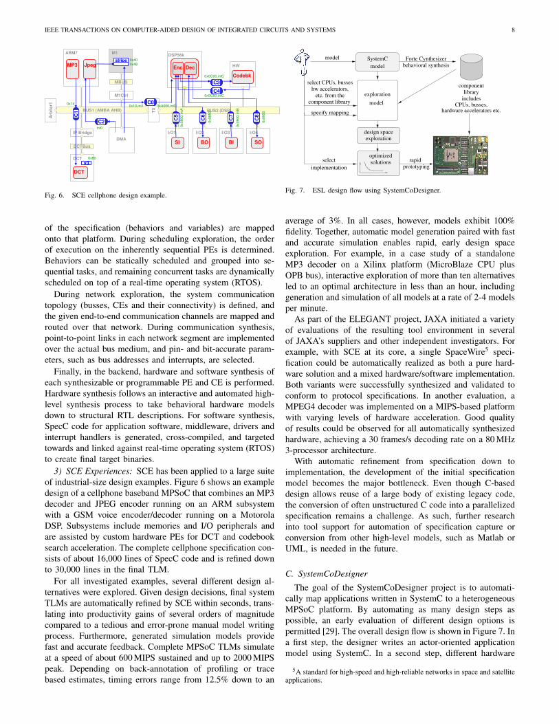
3) SCE Experiences: SCE has been applied to a large suiteof industrial-size design examples. Figure 6 shows an exampledesign of a cellphone baseband MPSoC that combines an MP3decoder and JPEG encoder running on an ARM subsystemwith a GSM voice encoder/decoder running on a MotorolaDSP. Subsystems include memories and I/O peripherals andare assisted by custom hardware PEs for DCT and codebooksearch acceleration. The complete cellphone specification con-sists of about 16,000 lines of SpecC code and is refined downto 30,000 lines in the final TLM.
For all investigated examples, several different design al-ternatives were explored. Given design decisions, final systemTLMs are automatically refined by SCE within seconds, trans-lating into productivity gains of several orders of magnitudecompared to a tedious and error-prone manual model writingprocess. Furthermore, generated simulation models providefast and accurate feedback. Complete MPSoC TLMs simulateat a speed of about 600 MIPS sustained and up to 2000 MIPSpeak. Depending on back-annotation of profiling or tracebased estimates, timing errors range from 12.5% down to an
model
select CPUs, busses
component library
specify mapping
behavioral synthesisForte Cynthesizer
componentlibrary
hardware accelerators etc.CPUs, busses,
includes
rapidprototyping
select
implementation
hw accelerators,etc. from the
solutionsoptimized
model
SystemC
exploration
model
design spaceexploration
Fig. 7. ESL design flow using SystemCoDesigner.
average of 3%. In all cases, however, models exhibit 100%fidelity. Together, automatic model generation paired with fastand accurate simulation enables rapid, early design spaceexploration. For example, in a case study of a standaloneMP3 decoder on a Xilinx platform (MicroBlaze CPU plusOPB bus), interactive exploration of more than ten alternativesled to an optimal architecture in less than an hour, includinggeneration and simulation of all models at a rate of 2-4 modelsper minute.
As part of the ELEGANT project, JAXA initiated a varietyof evaluations of the resulting tool environment in severalof JAXA’s suppliers and other independent investigators. Forexample, with SCE at its core, a single SpaceWire5 speci-fication could be automatically realized as both a pure hard-ware solution and a mixed hardware/software implementation.Both variants were successfully synthesized and validated toconform to protocol specifications. In another evaluation, aMPEG4 decoder was implemented on a MIPS-based platformwith varying levels of hardware acceleration. Good qualityof results could be observed for all automatically synthesizedhardware, achieving a 30 frames/s decoding rate on a 80 MHz3-processor architecture.
With automatic refinement from specification down toimplementation, the development of the initial specificationmodel becomes the major bottleneck. Even though C-baseddesign allows reuse of a large body of existing legacy code,the conversion of often unstructured C code into a parallelizedspecification remains a challenge. As such, further researchinto tool support for automation of specification capture orconversion from other high-level models, such as Matlab orUML, is needed in the future.
C. SystemCoDesignerThe goal of the SystemCoDesigner project is to automati-
cally map applications written in SystemC to a heterogeneousMPSoC platform. By automating as many design steps aspossible, an early evaluation of different design options ispermitted [29]. The overall design flow is shown in Figure 7. Ina first step, the designer writes an actor-oriented applicationmodel using SystemC. In a second step, different hardware
5A standard for high-speed and high-reliable networks in space and satelliteapplications.

IEEE TRANSACTIONS ON COMPUTER-AIDED DESIGN OF INTEGRATED CIRCUITS AND SYSTEMS 9
accelerators are automatically generated for actors and storedin a component library. This library also contains other syn-thesizable IP cores like processors, busses or memories. Thedesigner defines an MPSoC platform model from resourcesin the component library as well as mapping constraintsfor the actors, resulting in a system-level specification. Anautomatic design space exploration trades off several, oftenconflicting, design objectives. From the set of optimizedsolutions, the designer selects promising implementations forrapid prototyping. For this purpose, design decision leadingto the optimized solution are represented as structural TLM.For rapid prototyping, hardware accelerators are synthesizedto the RT level and software is compiled to match the ISA ofselected processors.
1) Scope of Methodology: Currently, SystemCoDesignersupports the design of streaming applications. These applica-tions are typically modeled by help of dataflow graphs wherevertices represent actors and edges represent data dependen-cies. Due to the complexity of many streaming applications,they often cannot be modeled as static dataflow graphs [30],[31], where consumption and production rates are known atcompile time. Rather they are described as a combinationof static and dynamic dataflow models, e.g., Kahn ProcessNetworks [22].
On the other hand, SystemC [32] is becoming a new de-facto standard in industrial system-level design flows. Hence,SystemCoDesigner assumes that the application model iswritten in SystemC and represents a dataflow model, i.e., Sys-temC modules (actors) only communicate via SystemC FIFOchannels and their functionality is implemented in a singleSystemC thread. Such input descriptions can be transformedinto a special subset of SystemC called SysteMoC [29]. Anapplication modeled in SysteMoC resembles the FunStateMoC (Functions driven by State machines) [33] that allows toexpress non-deterministic dynamic dataflow (DDF) models.
A SysteMoC model is composed of SysteMoC actors thatcommunicate via queues with FIFO semantics. Each Syste-MoC actor is defined by a finite state machine (FSM) specify-ing the communication behavior and methods controlled by thefinite state machine. If activated by the FSM, these methodsare executed atomically and data consumption and productionis only performed after computing a method.
As an example, Figure 8(a) shows a Motion-JPEG decoderin SysteMoC. It consists of several actors interconnected bycommunication channels (edges) processing a stream of data.Figure 8(b) exemplarily shows the SystemC definition of thePPM sink actor. The corresponding representation as Syste-MoC actor is shown in Figure 8(c). The finite state machinecontrolling the communication behavior of the SysteMoCactor checks for available input data (e.g., #i1 ! 1) andavailable space on the output channels (e.g., #o1 ! 1) tostore results. Furthermore, constant methods called guards(e.g., check) can be used to test values of internal variablesand data in the input channels. If predicates annotated to astate transition evaluate to true, this transition can be takenand annotated action methods (e.g., transform) will beprocessed atomically.
SysteMoC actors can be transformed into both hardware
check
return(false);
return(true);}pixels=dimX*dimY;
sizedimX = i2[0];dimY = i2[1];
printHeader();n=0;
dimX = i2.read();dimY = i2.read();
JPEG Huff.Decoder
InverseZRL
DCDecoder
InverseQuant.
PPMSinkDecoder
FrameShuffler
IDCTInverseZigZag
Dup
ParserSource
YCbCr
(b)
(a)
qstart qloop
#i2 ! 2 / size
& !check / transform#i1 ! 1&#o1 ! 1
o1
i2
i1
(c)
class PPMSink: public sc module {void process() {
}}
}
for(int n=0; n<pixels;n++)
while(1) {
if(n<pixels) {transform
check
n++;printPixel(i1[0]);
printHeader();
printPixel(i1.read());
pixels = dimX*dimY;
Fig. 8. Block diagram of a Motion-JPEG decoder. b) shows the SystemCcode of an actor that can be transformed into a SysteMoC actor given in c).
accelerators and software modules [29]. The latter one isachieved by straight forward code transformations, whereas thehardware accelerators are built by help of Forte Cynthesizer[9]. This allows for quick extraction of important performanceparameters like the achieved throughput and the required areawhich are used to calibrate the system-level specification.The generated hardware accelerators (synthesizable RTL code)are stored in the component library. This component librarycontains further synthesizable IP cores including processors,busses, memories, etc. The MoA is a heterogeneous MPSoCplatform which is specified by instantiating and connectingcores from the component library. Furthermore, the designerhas to specify mapping constraints for each SysteMoC actor.Later, design space exploration is performed to find sets ofoptimized solutions.
From the set of optimized solutions the designer selects anyMPSoC implementation best suited for his needs. Once thisselection has been made, the last step of the proposed ESL de-sign flow is the rapid prototyping of the corresponding FPGA-based implementation in terms of model refinement. For thispurpose, the resulting platform is assembled. Moreover, theprogram code for each processor is generated according to thebinding of the actors. This results in a TLM, which is the MoSused as implementation representation by SystemCoDesigner.In order to generate high quality software schedules, System-

IEEE TRANSACTIONS ON COMPUTER-AIDED DESIGN OF INTEGRATED CIRCUITS AND SYSTEMS 10
CoDesigner supports the automatic classification of actors intosynchronous or cyclo-static dataflow [34] and clustering staticactors bound to the same processor into a single dynamicactor [35]. Finally, the implementation is compiled into anFPGA bit stream using the Xilinx Embedded DevelopmentKit (EDK) [36]. Thereby, connecting SystemCoDesigner tolower abstraction levels in the double roof model.
2) SystemCoDesigner Design Steps: All manual work inthe SystemCoDesigner design flow has been performed aftersetting up the MPSoC platform model together with themapping constraints. Starting with this input model, System-CoDesigner automatically explores the design space. For thispurpose, it optimizes the implementation of the streaming ap-plication while considering several objectives simultaneously,e.g., latency, throughput, area and power consumption. Whilearea consumption is assumed to be a linear cost function,timing and power estimation requires a simulation-based per-formance evaluation during exploration.
SystemCoDesigner generates task-accurate MoPs (TAPM)automatically from the SysteMoC model and the performancevalues annotated in the input model [29]. For this purpose,the MPSoC platform model is translated into a so calledvirtual architecture using again SystemC. The performanceevaluation is done by linking the SysteMoC model to thevirtual architecture. Each invocation of an action of an actoris then relayed to the virtual component the actor is bound to.The virtual component then blocks the actor’s execution untilthe estimated execution time of the action and possible otherpreemption times are expired.
Beside evaluating a single design point, design space explo-ration is responsible for covering the search space. In orderto perform decision making automatically, SystemCoDesignertranslates the input model into a Pseudo Boolean (PB) formula.The variables of this formula encode the resource allocation,the actor binding, the queue mapping, and the routing oftransactions on the communication structure. Each variableassignment satisfying this formula corresponds to a feasibleimplementation of the application. A Pseudo Boolean solveris used to identify these solutions [29]. The optimization isperformed using a Multi-Objective Evolutionary Algorithm.
3) SystemCoDesigner Experiences: For the experimentalevaluation of the SystemCoDesigner design flow, a Motion-JPEG decoder as shown in Figure 8(a) has been implemented.The Motion-JPEG decoder case study consists of 8, 000 Syste-MoC lines of code, supporting interleaved and non-interleavedbaseline profile without sub-sampling. The complete spec-ification results in about 5 · 1033 possible implementationalternatives. Thanks to the integration of Forte Cynthesizer, thehardware accelerators for the different actors could be obtaineddirectly from the SysteMoC specification. Furthermore, asSysteMoC offers a higher level of abstraction compared toRTL, the designer can progress more quickly. Taking thenumber of lines of code as a measure for complexity, the RTLdesign would have been 8" 10 times more costly.
With the specification the design space has been exploredusing SystemCoDesigner. The objectives taken into accountduring design space exploration have been (i) throughput, (ii)latency, (iii) number of required flip flops, (iv) look-up tables
and (v) block RAMs. During exploration 7,600 different solu-tions have been evaluated in 2 days, 17 hours and 46 minutes.The simulation time per solution is about 30 seconds forMotion-JPEG streams consisting of four QCIF frames. As aresult, 366 non-dominated solutions were found, each of themrepresenting an arbitrary hardware/software implementation.Hardware-only implementations show real-time performance(! 25frames/s) for QCIF streams while occupying about40, 000 4-input LUTs and 14, 500 flip flops.
Finally, many of these solutions have been automaticallyprototyped onto a Xilinx Virtex II FPGA. However, a dis-crepancy of up to 30% can be identified when comparing theFPGA implementations with the performance estimations dur-ing design space exploration. The differences in the requiredhardware sizes (# 15%) occurring between the predicted val-ues and those measured in hardware can be explained by postsynthesis optimization like elimination of useless BRAMs. Thediscrepancy between the performance estimations for latencyand throughput and those measured for hardware-softwaresolutions is due to schedule overhead.
IV. OTHER ESL SYNTHESIS METHODOLOGIES
In the following, we will present three more related aca-demic approaches. Note that in contrast to our own work forwhich we have additional details available, discussion of otherrelated work is limited to a classification of their underlyingmethodologies based on the criteria introduced in Section II.
A. MetropolisMetropolis [37] is a modeling and simulation environment
based on the platform-based design paradigm [38]. Platform-based design (PBD) is an attempt at simplifying the system-level design problem by removing one degree of freedom: inPBD, the allocation of the target system platform consistingof computation and communication components is assumedto be given or at least significantly constrained. As such,the constraints at the input of the design process contain afixed architecture template with no or little flexibility. Such apre-defined and pre-determined platform facilitates the reuseof common design patterns across different design instances.Therefore, PDB follows a meet-in-the-middle approach andthe system design problem is reduced to the mapping of adesired function onto the given target platform to create aspecific design instance.
Metropolis provides a general, proprietary metamodel lan-guage that is used to capture separate models for “func-tionality” (behavioral model), “architecture” (platform model)and their “mapping” (binding and scheduling). The meta-model employs a fundamental event-based execution modelwith concepts of concurrent processes communicating throughchannels (called media), including associated constraints andquantities. In a similar manner to other system-level languages,functionality is described in the form of event-driven processnetworks that are general in the sense that many classes ofMoCs can be represented. In addition, functionality can beannotated with non-functional constraints. The architecture isdefined following an MoA that uses processes and media

IEEE TRANSACTIONS ON COMPUTER-AIDED DESIGN OF INTEGRATED CIRCUITS AND SYSTEMS 11
to describe available resources (e.g. tasks) and services (e.g.CPUs, memories or busses), respectively. Quantities can beassociated with the architecture to define an MoP at the levelof tasks (TAPM). Finally, given a specification in the formof functionality and architecture, synthesis or refinement isperformed by defining an MoS as a mapping between thetwo through a set of additional constraints synchronizing theirevent execution.
Metropolis itself does not define any specific design toolsbut rather a general framework and language for modelingwith support for simulation, validation and analysis of models.Metropolis includes a frontend for parsing of metamodels anda backend for translation of metamodels into C++/SystemCsimulation code. In addition, several backend point tools haveemerged for scheduling, communication design, verification,and hardware synthesis [39].
B. Koski
The Koski design flow [40] provides a single infrastructurefor modeling of applications, automatic architectural designspace exploration, and automatic ESL synthesis, programming,and prototyping of selected MPSoCs. Koski’s design flowstarts with the capturing of requirements for an applicationand architecture, including design constraints, such as theoverall maximum cost. Subsequently, the functionality of thesystem is described with an application model in a UMLdesign environment (using the Statecharts MoC to describe theactual functionality) and verified with functional simulations.The architecture model consists of components which aretaken from a platform library, targeting the construction ofheterogeneous, bus-based MPSoCs (MoA). The relationshipbetween application and architecture models is described witha mapping model.
The UML interface handles the transformation of applica-tion and architecture models to an abstracted model for fastarchitecture exploration. Particularly, the application model istransformed to an abstract process network model. In addition,the UML interface can back-annotate the UML design withperformance information obtained from lower-level simula-tions. Finding a good application-to-architecture mapping iscarried out during a two-phase automatic architecture explo-ration step consisting of static and dynamic (i.e., simulative)exploration methods using a TAPM MoP. For controlling thearchitecture exploration, the designer constrains the designspace by defining the platform parts that can be used as well asthe allowed mapping combinations. In addition, the designerspecifies the constraints for performance, area, and power.
In the last step, the parts of the UML description thatwere mapped to processors during the architecture explorationare passed to the automatic code generation. The generatedlow-level software code and the RTL descriptions (i.e. anetlist MoS) of the component instances from the platform(derived from Koski’s platform library) are then combinedfor physical implementation. This stage also handles the real-time operating system (RTOS) integration, software executablegeneration, and hardware synthesis.
C. PeaCE/HOPES
PeaCE (Ptolemy extension as a Codesign Environment) [41]is an ESL synthesis framework for multimedia applications.Starting from a Ptolemy II application model, it provides aseamless codesign flow from functional simulation to systemsynthesis and prototyping. Although Ptolemy supports thehierarchical combination of many different Model of Com-putation, PeaCE restricts the input model to extension ofsynchronous dataflow and extended finite state machines. InPeaCE, the application is modeled by a task graph wheretasks are either signal processing tasks or control tasks.Signal processing tasks are modeled through synchronouspiggybacked dataflow, a dataflow model with control token.Control tasks are modeled by flexible finite state machines(hierarchical state machines without state transitions crossinghierarchy boundaries).
For functional simulation of the application model, PeaCEprovides an automatic C code generation. For system syn-thesis, the architecture platform is specified by a list ofprocessors and synthesizable IP cores resulting in a hetero-geneous MPSoC Model of Architecture. The design spaceexploration is a two-phased: In a first step the resourceallocation and task binding is performed. During this step,communication overhead is assumed to be proportional to theamount of consumed and produced data. The objective of thisstep is to minimize system cost under timing constraints. Inthe second step, the communication architecture exploration,that is bus and memory allocation is performed. For thispurpose, communication and memory traces are generated forthose solutions fulfilling the timing constraints in the firststep. Design space exploration in PeaCE can be performedautomatically or manually and is guided by an instruction setaccurate performance model. After design space exploration,optimized MPSoC implementations can be prototyped eitherusing a cosimulation environment or FPGAs. In both cases,the Model of Structure is a Netlist representing the designdecisions.
Recently, a new framework called HOPES has been pro-posed as enhancement to PeaCE [42]. The main focus is ongenerating MPSoC software and overcome the limitations ofOpenMP and MPI. Its input model is called CIC (CommonIntermediate Code). A CIC models consists of two parts: Thetask code defines each task by the three methods init(), go(),and wrapup(). Intertask communication or communication tothe environment is established by help of several APIs. Thesecond part is the architecture information, including theplatform definition and additional constraints. The task code ofa CIC model can be either written manually or automaticallygenerated from PeaCE models.
A CIC translator transforms a CIC model into optimizedsoftware for the processors in the MPSoC platform. For thispurpose, the API calls must be replaced by platform specificcode, interface code for hardware accelerators has to be gen-erated, and scheduling of tasks bound to the same processorhas to be performed. Optionally, an OpenMP compiler can beused for optimization.

IEEE TRANSACTIONS ON COMPUTER-AIDED DESIGN OF INTEGRATED CIRCUITS AND SYSTEMS 12
TABLE ICLASSIFICATION OF DIFFERENT ESL SYNTHESIS APPROACHES.
Specification Implementation Decision Making RefinementApproach MoC(1.1) MoA(1.2) MoS(2.1) MoP(2.2) DSE(3) Comp(4.1) Comm(4.2) Comp(5.1) Comm(5.2)
Daedalus KPN HeMPSoC Netlist T/ISAPM • • " • "Koski Statecharts HeMPSoC Netlist TAPM • • " • "
Metropolis PN HeMPSoC TLM TAPM " "PeaCE/HoPES DDF/FSM HeMPSoC Netlist ISAPM " " • "
SCE PSM HeMPSoC TLM/Netlist T/CAPM • •SystemCoDesigner DDF HeMPSoC TLM TAPM • • • •
DDF Dynamic Dataflow(K)PN (Kahn) Process Network
PSM Program State Machine
HeMPSoC Heterogeneous, Bus-Based Multi-Processor System-On-Chip
TLM Transaction-Level Model
TAPM Task Accurate Performance ModelISAPM Instruction Set Accurate Performance ModelCAPM Cycle-Accurate Performance Model
V. DISCUSSION
A summary of all six presented tools based on the classifi-cation criteria introduced in Section II is given in Table I. Inthis table, a full circle implies that a certain synthesis aspect(DSE, decision making or refinement) is taken care of in afully automated fashion by an ESL synthesis approach, whilean open circle means partial support/automation.
As can be seen, tools share many common characteristics.For example, all discussed tools target heterogeneous, bus-based MPSoCs and almost uniformly support task-based per-formance models. On the other hand, tools each have theirparticular strengths and weaknesses, specifically in the levelof automation for different design tasks. All together, this pro-vides a tremendous opportunity to exploit tool synergies. Bymerging automation capabilities of different tools, a completeESL synthesis solution should be achievable. We are currentlyin the process of exploring such integration of our own tools,e.g. by combining DSE and decision making algorithms ofSystemCoDesigner with SCE’s refinement engine.
One of the biggest hurdles for tool interoperability willalways remain the definition of proper, standardized interfaces.As part of our integration work, we expect to obtain insightsinto requirements for such interfaces, e.g. for a canonical de-sign decision description format between decision making andrefinement. Another open question is the choice of MoC at thespecification level. While restricted MoCs show the potentialto perform domain specific optimizations, other more generalMoCs should be used for expressing implementation detailsand, even, conducting platform-dependent optimization steps.As both aspects are important ingredients for ESL synthesistools, a well-defined MoC hierarchy and MoC interoperabilitymight help to improve future design methodologies at thesystem level.
On the modeling side, language and MoS standardizationefforts such as SpecC or SystemC consortia, TLM standardsand the IP-XACT netlist format are only a first step into thisdirection. As exemplified by the various tools presented in thispaper, standardized languages can provide a common basis forexchange of design models between different point tools anddesign steps, even across different vendors as demonstrated bythe SCE/ELEGANT project. However, experiences from theseprojects also showed that synthesis nevertheless requires tightintegration for exchange of semantic meta-information on topof basic, inherently ambiguous simulation languages.
In general, interoperability issues will require an industry-wide approach. In this sense, it may be worthwhile to considerthe definition and development of a Common Design FlowInfrastructure (CDFI) which facilitates the development ofsystem-level design flows and fosters the re-use of designtools. Such a CDFI would be a kind of meta-tool for devel-oping system-level design flows, having design flow steps asplug-ins, i.e. similar to the goals of the Metropolis project. Thisrequires the definition (and broad adoption) of standardizedtool, model and data descriptions and file formats to allowthe interchange of information between the CDFI frameworkand external tools (i.e., plug-ins). Moreover, the frameworkcould also allow for explicitly defining design flows, whichwould make it possible to build pre-packaged standardized orcustomized design flows.
Finally, the synergy between the various ESL synthesisefforts also necessitates the development of standard casestudies and benchmarks for ESL design. This would invigorateESL synthesis research as it enables the direct comparisonof research results. Currently, such a comparison betweenESL synthesis research efforts in terms of their qualitativecharacteristics, remains difficult. We also believe that the flowof ideas from academia to industry will benefit from good,standardized benchmarks and case studies, as research resultscan always be demonstrated on industrially relevant examples.
VI. SUMMARY AND CONCLUSIONS
Being an active research topic at its relative infancy, the ESLspace is as of yet characterized by fragmentation and partialor wrongly positioned solutions. In this paper, we developedand proposed a classification framework for evaluation ofdifferent ESL synthesis approaches. Within the context ofthis framework, we presented a comparison and analysis ofsix different state-of-the art ESL tools. These observationsshow that recent approaches are converging towards largelysimilar design principles and flows. Nevertheless, no singleapproach currently provides a complete solution and furtherresearch in many areas is required. On the other hand, basedon the common concepts and principles identified in thisclassification, it should be possible to define interfaces suchthat different point tools can be combined into an overall ESLdesign environment. In the future, we plan to investigate suchinteroperability issues using combinations of different toolspresented in this paper.

IEEE TRANSACTIONS ON COMPUTER-AIDED DESIGN OF INTEGRATED CIRCUITS AND SYSTEMS 13
ACKNOWLEDGMENTS
Besides the authors, a large number of people are re-sponsible for, or have contributed to, the work described inSection III of this paper. The main co-contributors of theDaedalus framework are Hristo Nikolov, Mark Thompson,Cagkan Erbas, Simon Polstra, and Ed Deprettere. For SCE,we would like to acknowledge the main developers, namelyRainer Domer, Junyu Peng, Dongwan Shin and Quoc-VietDang. The main co-contributors to the SystemCoDesignerframework are Joachim Falk, Jens Gladigau, Michael Glaß,Joachim Keinert, Martin Lukasiewycz, Thomas Schlichter,Martin Streubuhr, and Christian Zebelein. Last, but not least,we would like to thank the reviewers for their helpful com-ments and suggestions in making this paper a much strongercontribution.
REFERENCES
[1] G. Martin, “Overview of the MPSoC design challenge,” in Proc. DAC,San Francisco, CA, Jul. 2006.
[2] D. Densmore, R. Passerone, and A. Sangiovanni-Vincentelli, “APlatform-Based Taxonomy for ESL Design,” IEEE Design & Test ofComputers, vol. September-October, pp. 359–374, 2006.
[3] E. A. Lee and A. Sangiovanni-Vincentelli, “A Framework for ComparingModels of Computation,” IEEE Trans. CAD of Integrated Circuits andSystems, vol. 17, no. 12, pp. 1217–1229, Dec. 1998.
[4] W. Wolf, A. A. Jerraya, and G. Martin, “Multiprocessor System-on-Chip (MPSoC) Technology,” IEEE Trans. CAD of Integrated Circuitsand Systems, vol. 27, no. 10, pp. 1701–1713, 2008.
[5] J. Teich, “Embedded System Synthesis and Optimization,” in Proceed-ings of the Workshop on System Design Automation (SDA 2000), Rathen,Germany, Mar. 2000, pp. 9–22.
[6] D. D. Gajski and R. H. Kuhn, “New VLSI tools,” IEEE Computer,vol. 16, no. 12, pp. 11–14, Dec. 1983.
[7] C. Zhu, Z. P. Gu, R. P. Dick, and L. Shang, “Reliable MultiprocessorSystem-On-Chip Synthesis,” in Proc. CODES+ISSS, 2007, pp. 239–244.
[8] S. Pasricha, N. Dutt, E. Bozorgzadeh, and M. Ben-Romdhane, “Fabsyn:Floorplan-aware bus architecture synthesis,” IEEE Trans. VLSI Systems,vol. 14, no. 3, pp. 241–253, March 2006.
[9] http://www.forteds.com.[10] NEC System Technologies, Ltd., “CyberWorkBench,”
http://www.necst.co.jp/product/cwb.[11] B. Kienhuis, E. Deprettere, P. van der Wolf, and K. Vissers, “A
methodology to design programmable embedded systems,” in EmbeddedProcessor Design Challenges: Systems, Architectures, Modeling, andSimulation (SAMOS). Springer, 2002, vol. 2268, pp. 18–37.
[12] M. Gries, “Methods for Evaluating and Covering the Design Spaceduring Early Design Development,” VLSI Journal, vol. 38, no. 2, pp.131–183, 2004.
[13] D. D. Gajski, F. Vahid, S. Narayan, and J. Gong, Specification andDesign of Embedded Systems. Prentice Hall, 1994.
[14] B. Kienhuis, E. Deprettere, K. Vissers, and P. van der Wolf, “AnApproach for Quantitative Analysis of Application-Specific DataflowArchitectures,” in Proceedings of the IEEE International Conferenceon Application-Specific Systems, Architectures and Processors, Zurich,Switzerland, Jul. 1997, pp. 338–349.
[15] K. Huang, S. Han, K. Popovici, L. Brisolara, X. Guerin, L. Li, X. Yan,S. Chae, L. Carro, and A. A. Jerraya, “Simulink-based MPSoC designflow: case study of Motion-JPEG and H.264,” in Proc. DAC, 2007, pp.39–42.
[16] G. Stitt and F. Vahid, “Binary synthesis,” ACM Trans. Design Automa-tion of Electronic Systems, vol. 12, no. 3, pp. 1–30, 2007.
[17] K.Lahiri, A.Raghunathan, and S.Dey, “Design space exploration foroptimizing on-chip communication architectures,” IEEE Trans. CAD ofIntegrated Circuits and Systems, vol. 23, no. 6, pp. 952–961, June 2004.
[18] F. Dumitrascu, I. Bacivarov, L. Pieralisi, M. Bonaciu, and A. A. Jerraya,“Flexible MPSoC platform with fast interconnect exploration for optimalsystem performance for a specific application,” 2006, pp. 166–171.
[19] S. Pasricha and N. Dutt, “A framework for co-synthesis of memoryand communication architectures for MPSoC,” IEEE Trans. CAD ofIntegrated Circuits and Systems, vol. 26, no. 3, pp. 408–420, March2007.
[20] M. Thompson, T. Stefanov, H. Nikolov, A. D. Pimentel, C. Erbas,S. Polstra, and E. F. Deprettere, “A framework for rapid system-levelexploration, synthesis, and programming of multimedia MP-SoCs,” inProc. CODES+ISSS, 2007, pp. 9–14.
[21] H. Nikolov, M. Thompson, T. Stefanov, A. D. Pimentel, S. Polstra,R. Bose, C. Zissulescu, and E. F. Deprettere, “Daedalus: Towardcomposable multimedia MP-SoC design,” in Proc. DAC, June 2008,pp. 574–579.
[22] G. Kahn, “The semantics of a simple language for parallel program-ming,” in Proc. of the IFIP Congress 74, 1974.
[23] S. Verdoolaege, H. Nikolov, and T. Stefanov, “PN: a tool for improvedderivation of process networks,” EURASIP Journal on Embedded Sys-tems, vol. vol. 2007, Article ID 75947, 2007.
[24] A. D. Pimentel, C. Erbas, and S. Polstra, “A systematic approach toexploring embedded system architectures at multiple abstraction levels,”IEEE Computer, vol. 55, no. 2, pp. 99–112, 2006.
[25] H. Nikolov, T. Stefanov, and E. F. Deprettere, “Systematic and automatedmulti-processor system design, programming, and implementation,”IEEE Trans. CAD of Integrated Circuits and Systems, vol. 27, no. 3,pp. 542–555, March 2008.
[26] R. Domer, A. Gerstlauer, J. Peng, D. Shin, L. Cai, H. Yu, S. Abdi, andD. Gajski, “System-on-Chip Environment: A SpecC-based Frameworkfor Heterogeneous MPSoC Design,” EURASIP Journal on EmbeddedSystems, vol. 2008, no. 647953, p. 13, 2008.
[27] D. D. Gajski, J. Zhu, R. Domer, A. Gerstlauer, and S. Zhao, SpecC:Specification Language and Design Methodology. Kluwer, 2000.
[28] A. Gerstlauer, J. Peng, D. Shin, D. Gajski, A. Nakamura, D. Araki,and Y. Nishihara, “Specify-Explore-Refine (SER): From specification toimplementation,” in Proc. DAC, Anaheim, CA, USA, June 2008, pp.586–591.
[29] J. Keinert, M. Streubuhr, T. Schlichter, J. Falk, J. Gladigau, C. Haubelt,J. Teich, and M. Meredith, “SystemCoDesigner - An Automatic ESLSynthesis Approach by Design Space Exploration and Behavioral Syn-thesis for Streaming Applications,” ACM Trans. Design Automation ofElectronic Systems, vol. 14, no. 1, pp. 1–23, 2009.
[30] E. A. Lee and D. G. Messerschmitt, “Synchronous Data Flow,” Proc.of the IEEE, vol. 75, no. 9, pp. 1235–1245, Sep. 1987.
[31] G. Bilsen, M. Engels, R. Lauwereins, and J. Peperstraete, “Cyclo-StaticDataflow,” IEEE Trans. Signal Processing, vol. 44, no. 2, pp. 397–408,Feb. 1996.
[32] T. Grotker, S. Liao, G. Martin, and S. Swan, System Design withSystemC. Kluwer, 2002.
[33] K. Strehl, L. Thiele, M. Gries, D. Ziegenbein, R. Ernst, and J. Teich,“FunState - An Internal Design Representation for Codesign,” IEEETrans. VLSI Systems, vol. 9, no. 4, pp. 524–544, Aug. 2001.
[34] C. Zebelein, J. Falk, C. Haubelt, and J. Teich, “Classification of GeneralData Flow Actors into Known Models of Computation,” in Proc.MEMOCODE, Anaheim, CA, USA, Jun. 2008, pp. 119–128.
[35] J. Falk, J. Keinert, C. Haubelt, J. Teich, and S. Bhattacharyya, “A Gen-eralized Static Data Flow Clustering Algorithm for MPSoC Schedulingof Multimedia Applications,” in Proc. EMSOFT, Atlanta GA, USA, Oct.2008, to appear.
[36] Embedded SystemTools Reference Manual - Embedded DevelopmentKit EDK 8.1ia, XILINX, October 2005. [Online]. Available:http://www.xilinx.com/ise/embedded/est rm.pdf
[37] F. Balarin, Y. Watanabe, H. Hsieh, L. Lavagno, C. Passerone, andA. Sangiovanni-Vincentelli, “Metropolis: An integrated electronic sys-tem design environment,” IEEE Computer, vol. 36, no. 4, pp. 45–52,April 2003.
[38] A. Sangiovanni-Vincentelli, “Quo Vadis SLD: Reasoning about theTrends and Challenges of System Level Design,” Proceedings of theIEEE, vol. 95, no. 3, pp. 467–506, March 2007. [Online]. Available:http://chess.eecs.berkeley.edu/pubs/263.html
[39] Gigascale Systems Research Center (GSRC), “Coredesign technology for complex heterogeneous systems,”http://www.gigascale.org/theme/core/.
[40] T. Kangas et al., “UML-based multi-processor SoC design framework,”ACM Trans. Embedded Computer Systems, vol. 5, no. 2, pp. 281–320,May 2006.
[41] S. Ha, S. Kim, C. Lee, Y. Yi, S. Kwon, and Y.-P. Joo, “PeaCE: AHardware-Software Codesign Environment of Multimedia EmbeddedSystems,” ACM Trans. Design Automation of Electronic Systems, vol. 12,no. 3, pp. 1–25, 2007.
[42] S. Kwon, Y. Kim, W.-C. Jeun, S. Ha, and Y. Paek, “A RetargetableParallel Programming Framework for MPSoC,” ACM Trans. DesignAutomation of Electronic Systems, vol. 13, no. 3, 2008.

IEEE TRANSACTIONS ON COMPUTER-AIDED DESIGN OF INTEGRATED CIRCUITS AND SYSTEMS 14
Andreas Gerstlauer is an Assistant Professor inElectrical and Computer Engineering at the Univer-sity of Texas at Austin. He received a Dipl.-Ing.degree in Eletrical Engineering from the Universityof Stuttgart, Germany in 1997 and M.S. and Ph.D.degrees in Information and Computer Science fromthe University of California, Irvine (UCI) in 1998and 2004, respectively. Prior to joining UT Austin in2008, he was an Assistant Researcher in the Centerfor Embedded Computer Systems (CECS) at UCIrvine, leading a research group to develop electronic
system-level (ESL) design tools. Dr. Gerstlauer serves on the program com-mittee of major conferences such as DATE and CODES+ISSS. His researchinterests include system-level design automation, system modeling, designlanguages and methodologies, and embedded hardware and software synthesis.
Christian Haubelt received his diploma degreein Electrical Engineering from the University ofPaderborn, Germany, in 2001 and received his Ph.D.degree in Computer Science from the Friedrich-Alexander-University of Erlangen-Nuremberg, Ger-many, in 2005. Christian Haubelt leads the System-level Design Automation group in the Departmentof Hardware-Software-Co-Design at the Universityof Erlangen-Nuremberg. Dr. Haubelt serves as areviewer for several well-known international con-ferences and journals. His special research interests
focus on Electronic System Level design, design space exploration, and Multi-Objective Evolutionary Algorithms.
Andy D. Pimentel is associate professor in theComputer Systems Architecture group of the In-formatics Institute at the University of Amsterdam.He holds the MSc and PhD degrees in computerscience, both from the University of Amsterdam. Heis co-founder of the International Symposium on em-bedded computer Systems: Architectures, Modeling,and Simulation (SAMOS) and is member of the Eu-ropean Network of Excellence on High-PerformanceEmbedded Architecture and Compilation (HiPEAC).His research interests include computer architecture,
computer architecture modeling and simulation, system-level design, designspace exploration, performance and power analysis, embedded systems, andparallel computing. He serves on the editorial boards of Elsevier’s SimulationModelling Practice and Theory as well as Springer’s Journal of SignalProcessing Systems. Moreover, he has also served on the organizationalcommittees for a range of leading conferences and workshops, such as DATE,IEEE ICCD, FPL, SAMOS, and IEEE ESTIMedia.
Todor P. Stefanov received the Dipl.Ing. and M.S.degrees in computer engineering from The TechnicalUniversity of Sofia, Sofia, Bulgaria, in 1998 andthe Ph.D. degree in computer science from LeidenUniversity, Leiden, The Netherlands, in 2004. From1998 to May 2000, he was a Research and Devel-opment Engineer with Innovative Micro Systems,Ltd., Sofia. From June 2000 to August 2007, hewas with the Leiden Institute of Advanced ComputerScience, Leiden University, where he was a ResearchAssistant (PhD student) and a PostDoc Researcher
at the Leiden Embedded Research Center. From September 2007 to August2008, he was a Senior Researcher at the Computer Engineering Lab, DelftUniversity of Technology, Delft, The Netherlands. Since September 1, 2008,Todor Stefanov has been an Assistant Professor with the Leiden Institute ofAdvanced Computer Science, Leiden University where he performs researchat the Leiden Embedded Research Center. His research interests includeseveral aspects of embedded systems design, with particular emphasis onsystem-level design automation, multiprocessor systems-on-chip design, andhardware/software codesign.
Daniel D. Gajski holds Dipl. Ing. and M.S. degreesin electrical engineering from the University ofZagreb, Croatia, and a doctoral degree in computerand information sciences from the University ofPennsylvania, Philadelphia.
After 10 years as Professor at University of Illi-nois he has joined University of California, Irvine,where he presently holds The Henry Samueli En-dowed Chair in Computer System Design. He directsthe UCI Center for Embedded Computer Systems,with a research mission to incorporate embedded
systems into automotive, communications, and medical applications. He hasauthored over 300 papers and numerous textbooks, including Principles ofDigital Design (Englewood Cliffs, NJ: Prentice Hall, 1997) that has beentranslated into several languages.
Jurgen Teich received his masters degree (Dipl.-Ing.) in 1989 from the University of Kaiserslautern(with honors). From 1989 to 1993, he was PhDstudent at the University of Saarland, Saarbrucken,Germany, where he received his PhD degree (summacum laude). In 1994, Dr. Teich joined the DSPdesign group at UC Berkeley, where he was workingin the Ptolemy project (PostDoc). From 1995 to1998, he held a position at the Institute of ComputerEngineering and Communications Networks Labora-tory (TIK) at ETH Zurich, Switzerland, finishing his
habilitation in 1996. From 1998 to 2002, he was full professor in the ElectricalEngineering and Information Technology department of the University ofPaderborn, holding a chair in Computer Engineering. Since 2003, he isappointed full professor in the Computer Science Institute of the Friedrich-Alexander University Erlangen-Nuremberg, holding a chair in Hardware-Software-Co-Design. Dr. Teich has been a member of multiple programcommittees of well-known conferences and program chair for CODES+ISSS2007 and FPL 2008. In 2004, Prof. Teich was elected reviewer for theGerman Science Foundation (DFG) for the area of Computer Architectureand Embedded Systems.