ieee transactions on antennas and … s. rappaport, fellow, ieee, ... mmwave wireless communication...
TRANSCRIPT

IEEE TRANSACTIONS ON ANTENNAS AND PROPAGATION, VOL. 65, NO. 12, DECEMBER 2017 6213
Overview of Millimeter Wave Communications forFifth-Generation (5G) Wireless Networks—With
a Focus on Propagation ModelsTheodore S. Rappaport, Fellow, IEEE, Yunchou Xing, Student Member, IEEE,
George R. MacCartney, Jr., Student Member, IEEE, Andreas F. Molisch, Fellow, IEEE,Evangelos Mellios, Member, IEEE, and Jianhua Zhang, Senior Member, IEEE
(Invited Paper)
Abstract— This paper provides an overview of the features offifth generation (5G) wireless communication systems now beingdeveloped for use in the millimeter wave (mmWave) frequencybands. Early results and key concepts of 5G networks arepresented, and the channel modeling efforts of many interna-tional groups for both licensed and unlicensed applications aredescribed here. Propagation parameters and channel models forunderstanding mmWave propagation, such as line-of-sight (LOS)probabilities, large-scale path loss, and building penetration loss,as modeled by various standardization bodies, are compared overthe 0.5–100 GHz range.
Index Terms— Cellular network, channel model standards,channel modeling, fifth generation (5G), millimeter wave(mmWave), path loss, propagation.
I. INTRODUCTION
W IRELESS data traffic has been increasing at a rateof over 50% per year per subscriber, and this trend
is expected to accelerate over the next decade with thecontinual use of video and the rise of the Internet-of-Things (IoT) [1], [2]. To address this demand, the wirelessindustry is moving to its fifth generation (5G) of cellular
Manuscript received December 21, 2016; revised April 18, 2017; acceptedMay 23, 2017. Date of publication August 1, 2017; date of current versionNovember 30, 2017. The work of T. S. Rappaport, Y. Xing, andG. R. MacCartney, Jr., was supported in part by the NYU WIRELESSIndustrial Affiliates: AT&T, CableLabs, nextlink, Ericsson, Huawei, IntelCorporation, InterDigital Inc., Keysight Technologies, L3 Communications,Nokia, National Instruments, Qualcomm Technologies, SiBeam, Straight PathCommunications, OPPO, Sprint, Verizon, and UMC, in part by the GAANNFellowship Program, and in part by the National Science Foundation underGrant 1320472, Grant 1237821, and Grant 1302336. The work ofA. F. Molisch was supported in part by the National Science Foundationand in part by Samsung. (Corresponding author: Theodore S. Rappaport.)
T. S. Rappaport, Y. Xing, and G. R. MacCartney, Jr., are with the NYUWIRELESS Research Center, NYU Tandon School of Engineering, Brooklyn,NY 11201 USA (e-mail: [email protected]; [email protected]; [email protected]).
A. F. Molisch is with the Ming Hsieh Department of Electrical Engineering,University of Southern California, Los Angeles, CA 90089 USA (e-mail:[email protected]).
E. Mellios is with the Communication Systems and NetworksGroup, University of Bristol, Bristol BS8 1UB, U.K. (e-mail:[email protected]).
J. Zhang is with the State Key Laboratory of Networking and Switch-ing Technology, Beijing University of Posts and Telecommunications,Beijing 100876, China (e-mail: [email protected]).
Color versions of one or more of the figures in this paper are availableonline at http://ieeexplore.ieee.org.
Digital Object Identifier 10.1109/TAP.2017.2734243
technology that will use millimeter wave (mmWave) frequen-cies to offer unprecedented spectrum and multi-Gigabit-per-second (Gbps) data rates to a mobile device [3]. Mobiledevices, such as cell phones, are typically referred to as userequipment (UE). A simple analysis illustrated that 1 GHz widechannels at 28 or 73 GHz could offer several Gbps of datarate to UE with modest phased array antennas at the mobilehandset [4], and early work showed 15 Gbps peak rates arepossible with 4×4 phased arrays antenna at the UE and 200 mspacing between base stations (BSs) [5], [6].
Promising studies such as these led the U.S. Federal Com-munications Commission (FCC) to authorize its 2016 “Spec-trum Frontiers” allocation of 10.85 GHz of mmWave spectrumfor 5G advancements [7], and several studies [8]–[11] haveproposed new mobile radio concepts to support 5G mobilenetworks.
5G mmWave wireless channel bandwidths will be more thanten times greater than today’s 4G Long-Term Evolution (LTE)20 MHz cellular channels. Since the wavelengths shrink byan order of magnitude at mmWave when compared to today’s4G microwave frequencies, diffraction and materialpenetration will incur greater attenuation, thus elevatingthe importance of line-of-sight (LOS) propagation, reflection,and scattering. Accurate propagation models are vital forthe design of new mmWave signaling protocols (e.g., airinterfaces). Over the past few years, measurements andmodels for a vast array of scenarios have been presented bymany companies and research groups [3], [4], [12]–[32].
This invited overview paper is organized as follows.Section II summarizes key 5G system concepts of emergingmmWave wireless communication networks and Section IIIpresents 5G propagation challenges and antenna technologies.Section IV gives a thorough compilation and comparison ofrecent mmWave channel models developed by various groupsand standard bodies, while Section V provides concludingremarks.
II. 5G SYSTEM CONCEPTS AND AIR INTERFACES
5G promises great flexibility to support a myriad of InternetProtocol (IP) devices, small cell architectures, and densecoverage areas. Applications envisioned for 5G include the
0018-926X © 2017 IEEE. Translations and content mining are permitted for academic research only. Personal use is also permitted,but republication/redistribution requires IEEE permission. See http://www.ieee.org/publications_standards/publications/rights/index.html for more information.

6214 IEEE TRANSACTIONS ON ANTENNAS AND PROPAGATION, VOL. 65, NO. 12, DECEMBER 2017
Fig. 1. Mobile networks are evolving from 4G toward 5G. Shown here are small cells, edge servers, wireless backhaul, and 5G multitier architecture.
Tactile Internet [33], vehicle-to-vehicle (V2V) communica-tion [34], vehicle-to-infrastructure (V2I) communication [35],as well as peer-to-peer and machine-to-machine communica-tion [36], all which will require extremely low network latencyand on-call demand for large bursts of data over minusculetime epochs [37]. Current 4G LTE and WiFi roundtrip laten-cies are about 20–60 ms [38], [39], but 5G will offer round-trip latencies on the order of 1 ms [40]. As shown in Fig. 1,today’s 4G cellular network is evolving to support 5G, whereWiFi off-loading, small cells, and distribution of widebanddata will rely on servers at the edges of the network (edgeservers) to enable new use cases with lower latency.
A. Backhaul and Fronthaul
Fig. 1 shows how backhaul connects the fixed cellularinfrastructure (e.g., BSs) to the core telephone network andthe Internet. Backhaul carries traffic between the local subnet-work (e.g., the connections between UE and BSs) and thecore network (e.g., the Internet and the Mobile SwitchingTelephone Office). In 4G and WiFi, the backhaul, and notthe air interface, is often the source of traffic bottlenecksin modern networks since backhaul connections provided bypacket-based Ethernet-over-Fiber links typically provide onlyabout 1 Gbps [41], which may be easily consumed by severalUEs. In a typical macrocell site, a baseband unit (BBU) isin an enclosure at the base of a remote cell site and isdirectly connected to the backhaul. The BBU processes andmodulates IP packet data from the core network into digitalbaseband signals where they are transmitted to remote radioheads (RRHs). The digital baseband signal travels from theBBU to an RRH via a common public radio interface (CPRI)through a digital radio-over-fiber (D-RoF) connection, alsoknown as fronthaul. The RRH converts the digital signal toanalog for transmission over the air at the carrier frequency byconnecting to amplifiers and antennas to transmit the downlink
from the cell tower. The RRH also converts the received radiofrequency (RF) uplink signal from the UEs into a digitalbaseband signal which travels from the RRH to the BBUvia the same CPRI and D-RoF connection to the base of thecell tower. The BBU then processes and packetizes the digitalbaseband signal from the RRH and sends it through a backhaulconnection to the core network. In summary, fronthaul is theconnection between the RRH and BBU in both directions andbackhaul is the connection between the BBU and the corenetwork in both directions.
Modern cellular architectures support a more flexibledeployment of radio resources that may be distributed usinga cloud radio access network technique, where a BS is splitinto two parts [42], one part where the RRHs are at remotecell sites, and in the other part, one centralized BBU islocated up to tens of kilometers away (see Fig. 1). CPRI isused for fronthaul, and interconnects the centralized BBU andmultiple RRHs through D-RoF. MmWave wireless backhauland fronthaul will offer fiber-like data rates and bandwidth toinfrastructure without the expense of deploying wired backhaulnetworks or long-range D-RoF [9], [43], [44].
B. Small Cells
An effective way to increase area spectral efficiency isto shrink cell size [40], [45], [46] where the reduced num-ber of users per cell, caused by cell shrinking, providesmore spectrum to each user. Total network capacity vastlyincreases by shrinking cells and reusing the spectrum, andfuture nomadic BSs and direct device-to-device connectionsbetween UEs are envisioned to emerge in 5G for evengreater capacity per user [47]. Femtocells that can dynamicallychange their connection to the operator’s core networkwill face challenges, such as managing RF interference andkeeping timing and synchronization, and various interference

RAPPAPORT et al.: OVERVIEW OF mmWAVE COMMUNICATIONS FOR 5G WIRELESS NETWORKS 6215
avoidance and adaptive power control strategies have beensuggested [45] concurrent with the move to high-speed base-band communications to RRHs. An analysis of the wirelessbackhaul traffic at 5.8, 28, and 60 GHz in two typicalnetwork architectures showed that spectral efficiency andenergy efficiency increased as the number of small cellsincreased [48], and backhaul RF measurements and modelsat 73 GHz were made in New York City [20], [49]. Workin [50] showed a theory for power consumption analysis,which is strikingly similar to noise figure, for compar-ing energy efficiency and power consumption in widebandnetworks. An early small-cell paper [51] gave insights intoenhancing user throughput, reducing signaling overhead, andreducing dropped call likelihoods.
C. Multi-tier Architecture
The roadmap for 5G networks will exploit a multi-tierarchitecture of larger coverage 4G cells with an underlyingnetwork of closer-spaced 5G BSs, as shown in Fig. 1. A multi-tier architecture allows users in different tiers to have differentpriorities for channel access and different kinds of connections(e.g., macrocells, small cells, and device-to-device connec-tions), thus supporting higher data rates, lower latencies,optimized energy consumption, and interference managementby using resource-aware criteria for the BS association andtraffic loads allocated over time and space [52]. Schemes andmodels for load balanced heterogeneous networks in a multi-tier architecture are given in [53] and [54]. 5G applications willalso require novel network architectures that support the con-vergence of different wireless technologies (e.g., WiFi, LTE,mmWave, and low-power IoT) that will interact in a flexibleand seamless manner using Software Defined Networking andNetwork Virtualization principles [55], [56].
D. 5G Air Interface
The design of new physical layer air interfaces is anactive area of 5G research. Signaling schemes that providelower latency, rapid beamforming, and synchronization, withmuch smaller time slots and better spectral efficiency thanthe orthogonal frequency division multiplexing (OFDM) usedin 4G, will emerge. A novel modulation that exploits thedead time in the single-carrier frequency domain modulationmethod used in today’s 4G LTE uplink is given in [5].Work in [10] reviews linear modulation schemes such as filterbank multicarrier (FBMC) modulation wherein subcarriers arepassed through filters that suppress sidelobes. Generalizedfrequency division multiplexing (GFDM) is proposed in [11],where it is shown that, when compared with OFDM used incurrent 4G LTE (which has one cyclic prefix per symbol andhigh out-of-band emissions [57]), GFDM improves the spec-tral efficiency and has approximately 15 dB weaker out-of-band emissions. Orthogonal time-frequency-space modulationthat spreads the signals in the time-frequency plane has alsobeen suggested, due to superior diversity and higher flexibilityin pilot design [58]. Channel state feedback and manage-ment to support directional beam search/steering will also bevital [59], [60].
E. 5G Unlicensed WiFi
MmWave WiFi for the 57–64 GHz unlicensed bandshas been in development for nearly a decade, with theWirelessHD and IEEE 802.11ad standardization processbeginning in 2007 and 2009, respectively [61]. IEEE 802.11addevices, which can reach 7 Gbps peak rates [62], andWirelessHD products, which can reach 4 Gbps with theoreticaldata rates as high as 25 Gbps [63], are both already availablein the market. Building on the history of WiFi standard IEEE802.11n [64], [65], two newer standards, IEEE 802.11ac and802.11ad, are amendments that improve the throughput toreach 1 Gbps in the 5 GHz band and up to 7 Gbps in the60 GHz band, respectively. An overview of IEEE Gigabitwireless local area network amendments (IEEE 802.11acand 802.11ad) [66]–[68] shows the suitability of these twostandards for multigigabit communications. For the 802.11adstandard [69], notable features include fast session transfer forseamless data rate fall back (and rate rise) between 60 GHzand 2.4/5 GHz PHYs, and media access control (MAC)enhancements for directional antennas, beamforming, back-haul, relays, and spatial reuse techniques. For enhancementsof the PHY layer, beamforming using directional anten-nas or antenna arrays is used to overcome the increased loss at60 GHz [61]. IEEE 802.11ay standard is an ongoing projectwith the goal to support a maximum throughput of at least20 Gbps in the 60 GHz unlicensed band [70] and the approvalof the first draft is expected by Nov. 2017. Newer WiFistandards are sure to emerge to exploit the new 64–71 GHzunlicensed spectrum in the U.S. [7].
F. Vehicular Networks
V2V communications are an important tool for increasingroad safety and reducing traffic congestion. Currently, the mostinvestigated system is the IEEE 802.11p standard which worksin 5.9 GHz band for V2V and V2I communications, and isknown as dedicated short-range communications [71]. ThemmWave bands (e.g., 24 and 77 GHz [7]) are attractive forV2V and V2I (e.g., cars, high-speed railway, and subwaysystems), since connected vehicles will need Gbps date rates,which cannot be achieved in the 10 MHz channel bandwidthsat 5.9 GHz in current 4G [72]–[74]. Limitations of V2Vconnectivity include the difficulty in achieving realistic spa-tial consistency to sustain the data-link connection for high-speed mobility vehicles [12], [75]. Evaluations have shownthat narrow beam directional antennas are more suitable forIEEE 802.11p-based systems [76], and several schemes aimedat utilizing adaptive antennas for fast moving V2V communi-cations are provided in [77].
III. 5G ANTENNA AND PROPAGATION CHALLENGES
The entire radio spectrum up to 5.8 GHz that has beenused for global wireless communications throughout the past100 years easily fits within the bandwidth of the single60 GHz unlicensed band, yet there is so much more spec-trum still available above 60 GHz [4], [7], [61], as shownin [61, p. 40, Fig. C.1]. With RF integrated circuits nowroutinely manufactured for 24 and 77 GHz vehicular radar,
6216 IEEE TRANSACTIONS ON ANTENNAS AND PROPAGATION, VOL. 65, NO. 12, DECEMBER 2017
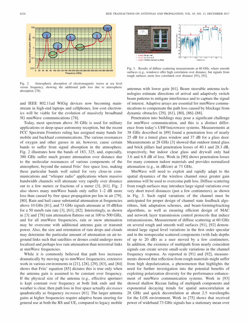
Fig. 2. Atmospheric absorption of electromagnetic waves at sea levelversus frequency, showing the additional path loss due to atmosphericabsorption [78].
and IEEE 802.11ad WiGig devices now becoming main-stream in high-end laptops and cellphones, low-cost electron-ics will be viable for the evolution of massively broadband5G mmWave communications [78].
Today, most spectrum above 30 GHz is used for militaryapplications or deep-space astronomy reception, but the recentFCC Spectrum Frontiers ruling has assigned many bands formobile and backhaul communications. The various resonancesof oxygen and other gasses in air, however, cause certainbands to suffer from signal absorption in the atmosphere.Fig. 2 illustrates how the bands of 183, 325, and, especially,380 GHz suffer much greater attenuation over distance dueto the molecular resonances of various components of theatmosphere, beyond the natural Friis’ free space loss, makingthese particular bands well suited for very close-in com-munications and “whisper radio” applications where massivebandwidth channels will attenuate very rapidly over distanceout to a few meters or fractions of a meter [3], [61]. Fig. 2also shows many mmWave bands only suffer 1–2 dB moreloss than caused by free space propagation per km in air [79],[80]. Rain and hail cause substantial attenuation at frequenciesabove 10 GHz [81], and 73 GHz signals attenuate at 10 dB/kmfor a 50 mm/h rain rate [3], [61], [82]. Interestingly, as shownin [3] and [78] rain attenuation flattens out at 100 to 500 GHz,and for all mmWave frequencies, rain or snow attenuationmay be overcome with additional antenna gain or transmitpower. Also, the size and orientation of rain drops and cloudsmay determine the particular amount of attenuation on air-to-ground links such that satellites or drones could undergo morelocalized and perhaps less rain attenuation than terrestrial linksat mmWave frequencies.
While it is commonly believed that path loss increasesdramatically by moving up to mmWave frequencies, extensivework in various environments in [21], [28], [29], [83], and [84]shows that Friis’ equation [85] dictates this is true only whenthe antenna gain is assumed to be constant over frequency.If the physical size of the antenna (e.g., effective aperture)is kept constant over frequency at both link ends and theweather is clear, then path loss in free space actually decreasesquadratically as frequency increases [61]. The larger antennagains at higher frequencies require adaptive beam steering forgeneral use at both the BS and UE, compared to legacy mobile
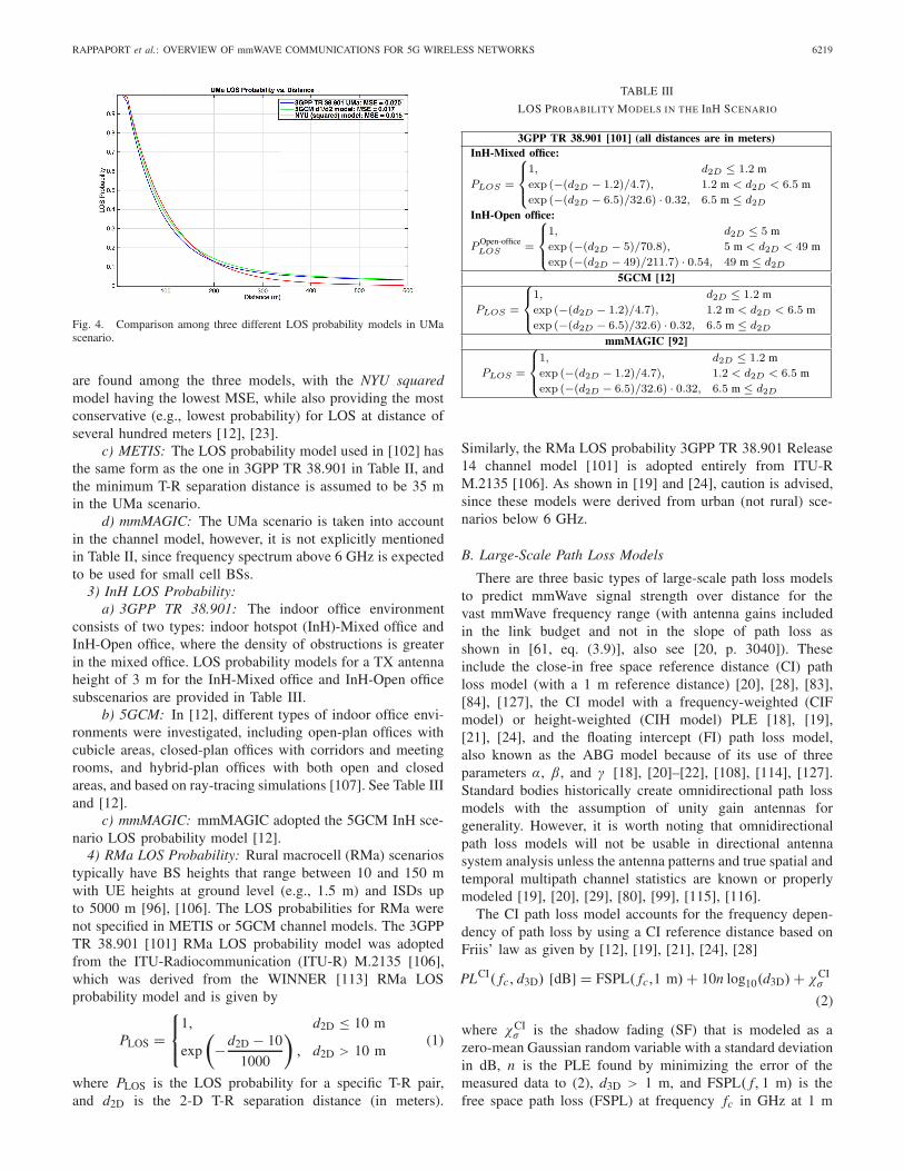
Fig. 3. Results of diffuse scattering measurements at 60 GHz, where smoothsurfaces (e.g., windows) offer high correlation over distance, but signals fromrough surfaces seem less correlated over distance [91], [92].
antennas with lower gain [61]. Beam steerable antenna tech-nologies estimate directions of arrival and adaptively switchbeam patterns to mitigate interference and to capture the signalof interest. Adaptive arrays are essential for mmWave commu-nications to compensate the path loss caused by blockage fromdynamic obstacles [29], [61], [80], [86]–[88].
Penetration into buildings may pose a significant challengefor mmWave communication, and this is a distinct differ-ence from today’s UHF/microwave systems. Measurements at38 GHz described in [89] found a penetration loss of nearly25 dB for a tinted glass window and 37 dB for a glass door.Measurements at 28 GHz [3] showed that outdoor tinted glassand brick pillars had penetration losses of 40.1 and 28.3 dB,respectively, but indoor clear glass and drywall only had3.6 and 6.8 dB of loss. Work in [90] shows penetration lossesfor many common indoor materials and provides normalizedattenuation (e.g., in dB/cm) at 73 GHz.
MmWave will need to exploit and rapidly adapt to thespatial dynamics of the wireless channel since greater gainantennas will be used to overcome path loss. Diffuse scatteringfrom rough surfaces may introduce large signal variations oververy short travel distances (just a few centimeters), as shownin Fig. 3. Such rapid variations of the channel must beanticipated for proper design of channel state feedback algo-rithms, link adaptation schemes, and beam-forming/trackingalgorithms, as well as ensuring efficient design of MACand network layer transmission control protocols that induceretransmissions. Measurement of diffuse scattering at 60 GHzon several rough and smooth wall surfaces [91], [92] demon-strated large signal level variations in the first order specularand in the nonspecular scattered components (with fade depthsof up to 20 dB) as a user moved by a few centimeters.In addition, the existence of multipath from nearly coincidentsignals can create severe small-scale variations in the channelfrequency response. As reported in [91] and [92], measure-ments showed that reflection from rough materials might sufferfrom high depolarization, a phenomenon that highlights theneed for further investigation into the potential benefits ofexploiting polarization diversity for the performance enhance-ment of mmWave communication systems. Work in [93]showed shallow Ricean fading of multipath components andexponential decaying trends for spatial autocorrelation at28 GHz and quick decorrelation at about 2.5 wavelengthsfor the LOS environment. Work in [75] shows that receivedpower of wideband 73 GHz signals has a stationary mean over

RAPPAPORT et al.: OVERVIEW OF mmWAVE COMMUNICATIONS FOR 5G WIRELESS NETWORKS 6217
slight movements but average power can change by 25 dBas the mobile transitioned around a building corner fromnon-line-of-sight (NLOS) to LOS in an urban microcell (UMi)environment [88], [94]. Measurements at 10, 20, and 26 GHzdemonstrate that diffraction loss can be predicted using well-known models as a mobile moves around a corner usingdirectional antennas [95], and human body blockage causesmore than 40 dB of fading [88], [94].
It is not obvious that the stationarity region size or small-scale statistics derived from 3GPP TR 36.873 [96] and othersub-6 GHz channel models, or those used by 3GPP or Inter-national Telecommunications Union (ITU) above 6 GHz arevalid for mmWave channels [80], [97]–[100]. Recent measure-ments [75], [91], [94] indicate very sharp spatial decorrelationover small distance movements of just a few tens of wave-lengths at mmWave, depending on antenna orientation, butmore work is needed in this area. The necessity and properform of spatial consistency, if borne out by measurements,have yet to be fully understood by the research community.
IV. CHANNEL MODELING
Channel models are required for simulating propagationin a reproducible and cost-effective way, and are used toaccurately design and compare radio air interfaces and sys-tem deployment. Common wireless channel model parametersinclude carrier frequency, bandwidth, 2-D or 3-D distancebetween transmitter (TX) and receiver (RX), environmentaleffects, and other requirements needed to build globally stan-dardized equipment and systems. The definitive challenge fora 5G channel model is to provide a fundamental physicalbasis, while being flexible and accurate, especially acrossa wide frequency range such as 0.5–100 GHz. Recently,a great deal of research aimed at understanding the propagationmechanisms and channel behavior at the frequencies above6 GHz has been published [3], [4], [12]–[32], [40], [60], [73],[75], [78], [81], [83], [84], [89]–[95], [101]–[111]. The specifictypes of antennas used and numbers of measurements collectedvary widely and may generally be found in the referencedwork.
For the remainder of this paper, the models for LOSprobability, path loss, and building penetration introduced byfour major organizations in the past two years are reviewedand compared. These organizations include:
1) The 3rd Generation Partnership Project (3GPP TR38.901 [101]), which attempts to provide channel modelsfrom 0.5–100 GHz based on a modification of 3GPP’sextensive effort to develop models from 6 to 100 GHz inTR 38.900 [112]. 3GPP TR documents are a continualwork in progress and serve as the international industrystandard for 5G cellular.
2) 5G Channel Model (5GCM) [12], an ad-hoc groupof 15 companies and universities that developed modelsbased on extensive measurement campaigns and helpedseed 3GPP understanding for TR 38.900 [112].
3) Mobile and wireless communications Enablers for theTwenty–twenty Information Society (METIS) [102], alarge research project sponsored by European Union.
4) Millimeter-Wave Based Mobile Radio Access Networkfor 5G Integrated Communications (mmMAGIC)[92], another large research project sponsored by theEuropean Union.
While many of the participants overlap in these standardsbodies, the final models between those groups are somewhatdistinct. It is important to note that recent work has found dis-crepancies between standardized models and measured results[29], [99], [100].
A. LOS Probability Model
The mobile industry has found benefit in describing pathloss for both LOS and NLOS conditions separately. As aconsequence, models for the probability of LOS are required,i.e., statistical models are needed to predict the likelihood thata UE is within a clear LOS of the BS, or in an NLOS regiondue to obstructions. LOS propagation will offer more reliableperformance in mmWave communications as compared toNLOS conditions, given the greater diffraction loss at higherfrequencies compared to sub-6 GHz bands where diffraction isa dominant propagation mechanism [75], [95], and given thelarger path loss exponent (PLE) as well as increased shadow-ing variance in NLOS as compared to LOS [28]. The LOSprobability is modeled as a function of the 2-D TX–RX (T-R)separation distance and is frequency-independent, as it issolely based on the geometry and layout of an environ-ment or scenario [23]. In the approach of 5GCM [12], the LOSstate is determined by a map-based approach in which onlythe TX and the RX positions are considered for determiningif the direct path between the TX and RX is blocked.
1) UMi LOS Probability: The UMi scenarios include highuser density open areas and street canyons with BS heightsbelow rooftops (e.g., 3–20 m), UE heights at ground level(e.g., 1.5 m), and intersite distances (ISDs) of 200 m orless [96], [106]. The UMi LOS probability models developedby the various parties are provided in Table I and are detailedin the following.
a) 3GPP TR 38.901: The antenna height is assumed to be10 m in the UMi LOS probability model [101] and the modelis referred to as the 3GPP/ITU d1/d2 model (it originatesin [96] and [106]), with d1 and d2 curve-fit parameters shownin Table I. In [101], model parameters were found to bed1 = 18 m and d2 = 36 m for UMi. For a link betweenan outdoor BS and an indoor UE, the model uses the outdoordistance d2D−out, which is the distance from the BS to thesurface of the indoor building, to replace d2D.
b) 5GCM: GCM provides two LOS probability models,the first one is identical in form to the 3GPP TR 38.901 out-door model [101], but with slightly different curve-fitparameters (d1 and d2). The second LOS probability model isthe NYU squared model [23], which improves the accuracy ofthe d1/d2 model by including a square on the whole term. TheNYU model was developed using a much finer resolution inter-section test than used by 3GPP TR 38.901, and used a real-world database in downtown New York City [23]. For UMi,the 5GCM d1/d2 model has a slightly smaller mean squareerror (MSE), but the NYU squared model has a more realisticand rapid decay over distance for urban clutter [12], [23].

6218 IEEE TRANSACTIONS ON ANTENNAS AND PROPAGATION, VOL. 65, NO. 12, DECEMBER 2017
TABLE I
LOS PROBABILITY MODELS IN THE UMi SCENARIO
TABLE II
LOS PROBABILITY MODELS FOR THE UMa SCENARIO
c) METIS: The LOS probability model used inMETIS [102] is based on the work of 3GPP TR 36.873 [96],and has the same form and the same parameter values as the3GPP TR 38.901 model in Table I where the minimum T-Rseparation distance is assumed to be 10 m in the UMi scenario.
d) mmMAGIC: For the UMi scenario, the mmMAGICLOS probability model and parameter values are identical tothe 3GPP TR 38.901 LOS probability model [101].
2) UMa LOS Probability: Urban macrocell (UMa) scenar-ios typically have BSs mounted above rooftop levels of sur-rounding buildings (e.g., 25–30 m) with UE heights at groundlevel (e.g., 1.5 m) and ISDs no more than 500 m [96], [106].The UMa LOS probability models are given in Table II andare identical to the UMi LOS probability models but withdifferent d1 and d2 values.
a) 3GPP TR 38.901: The 3GPP TR 38.901 UMa LOSprobability models for outdoor and indoor users are presentedin Table II, where for indoor users, d2D-out is used insteadof d2D and the models are derived assuming the TX antennaheight is 25 m. Due to the larger antenna heights in the UMascenario, mobile height is an added parameter of the LOSprobability, as shown in Table II, where hUE represents theUE antenna height above ground.
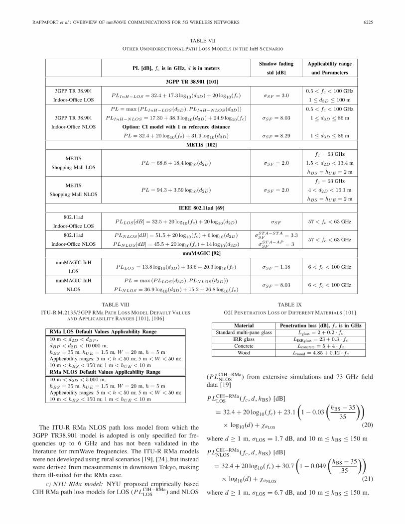
b) 5GCM: The UMa LOS probability models in the5GCM white paper [12] are of the same form as those in 3GPPTR 38.901 [101], but with different d1 and d2 values. The5GCM includes the NYU squared option [23], similar to theUMi scenario. Differences between the 3GPP TR 38.901 and5GCM UMa LOS probability models are given via MSEin Fig. 4 for a UE height of 1.5 m. Similar performances
RAPPAPORT et al.: OVERVIEW OF mmWAVE COMMUNICATIONS FOR 5G WIRELESS NETWORKS 6219
Fig. 4. Comparison among three different LOS probability models in UMascenario.
are found among the three models, with the NYU squaredmodel having the lowest MSE, while also providing the mostconservative (e.g., lowest probability) for LOS at distance ofseveral hundred meters [12], [23].
c) METIS: The LOS probability model used in [102] hasthe same form as the one in 3GPP TR 38.901 in Table II, andthe minimum T-R separation distance is assumed to be 35 min the UMa scenario.
d) mmMAGIC: The UMa scenario is taken into accountin the channel model, however, it is not explicitly mentionedin Table II, since frequency spectrum above 6 GHz is expectedto be used for small cell BSs.
3) InH LOS Probability:a) 3GPP TR 38.901: The indoor office environment
consists of two types: indoor hotspot (InH)-Mixed office andInH-Open office, where the density of obstructions is greaterin the mixed office. LOS probability models for a TX antennaheight of 3 m for the InH-Mixed office and InH-Open officesubscenarios are provided in Table III.
b) 5GCM: In [12], different types of indoor office envi-ronments were investigated, including open-plan offices withcubicle areas, closed-plan offices with corridors and meetingrooms, and hybrid-plan offices with both open and closedareas, and based on ray-tracing simulations [107]. See Table IIIand [12].
c) mmMAGIC: mmMAGIC adopted the 5GCM InH sce-nario LOS probability model [12].
4) RMa LOS Probability: Rural macrocell (RMa) scenariostypically have BS heights that range between 10 and 150 mwith UE heights at ground level (e.g., 1.5 m) and ISDs upto 5000 m [96], [106]. The LOS probabilities for RMa werenot specified in METIS or 5GCM channel models. The 3GPPTR 38.901 [101] RMa LOS probability model was adoptedfrom the ITU-Radiocommunication (ITU-R) M.2135 [106],which was derived from the WINNER [113] RMa LOSprobability model and is given by
PLOS =⎧⎨
⎩
1, d2D ≤ 10 m
exp
(
−d2D − 10
1000
)
, d2D > 10 m(1)
where PLOS is the LOS probability for a specific T-R pair,and d2D is the 2-D T-R separation distance (in meters).
TABLE III
LOS PROBABILITY MODELS IN THE InH SCENARIO
Similarly, the RMa LOS probability 3GPP TR 38.901 Release14 channel model [101] is adopted entirely from ITU-RM.2135 [106]. As shown in [19] and [24], caution is advised,since these models were derived from urban (not rural) sce-narios below 6 GHz.
B. Large-Scale Path Loss Models
There are three basic types of large-scale path loss modelsto predict mmWave signal strength over distance for thevast mmWave frequency range (with antenna gains includedin the link budget and not in the slope of path loss asshown in [61, eq. (3.9)], also see [20, p. 3040]). Theseinclude the close-in free space reference distance (CI) pathloss model (with a 1 m reference distance) [20], [28], [83],[84], [127], the CI model with a frequency-weighted (CIFmodel) or height-weighted (CIH model) PLE [18], [19],[21], [24], and the floating intercept (FI) path loss model,also known as the ABG model because of its use of threeparameters α, β, and γ [18], [20]–[22], [108], [114], [127].Standard bodies historically create omnidirectional path lossmodels with the assumption of unity gain antennas forgenerality. However, it is worth noting that omnidirectionalpath loss models will not be usable in directional antennasystem analysis unless the antenna patterns and true spatial andtemporal multipath channel statistics are known or properlymodeled [19], [20], [29], [80], [99], [115], [116].
The CI path loss model accounts for the frequency depen-dency of path loss by using a CI reference distance based onFriis’ law as given by [12], [19], [21], [24], [28]
PLCI( fc, d3D) [dB] = FSPL( fc,1 m) + 10n log10(d3D) + χCIσ
(2)
where χCIσ is the shadow fading (SF) that is modeled as a
zero-mean Gaussian random variable with a standard deviationin dB, n is the PLE found by minimizing the error of themeasured data to (2), d3D > 1 m, and FSPL( f, 1 m) is thefree space path loss (FSPL) at frequency fc in GHz at 1 m

6220 IEEE TRANSACTIONS ON ANTENNAS AND PROPAGATION, VOL. 65, NO. 12, DECEMBER 2017
TABLE IV
OMNIDIRECTIONAL PATH LOSS MODELS IN THE UMi SCENARIO
and is calculated by [19], [85]
FSPL( fc, 1 m) = 20 log10
(4π fc × 109
c
)
= 32.4 + 20 log10( fc) [dB] (3)
where c is the speed of light, 3×10⁸ m/s. Using (3), it is clearthat (2) can be represented as given in Table IV. The standarddeviation σ yields insight into the statistical variation aboutthe distant-dependent mean path loss [61].
The CI model ties path loss at any frequency to the physicalFSPL at 1 m according to Friis’ free space equation [85],and has been shown to be robust and accurate in variousscenarios [19], [24], [27], [28]. Indoor environments, however,were found to have frequency-dependent loss beyond the first
meter, due to the surrounding environment, and work in [21]extended the CI model to the CIF model where the PLE has afrequency-dependent term. Recent work [19], [24] has made73 GHz rural measurements to beyond 10 km and adaptedthe CIF model form to predict path loss as a function of TXantenna height in RMa scenarios, as path loss was found tobe accurately predicted with a height dependency in the PLE,leading to the CIH model,1 which has the same form of the
1The CIH model has the same form as (4) except the PLE isa function of the BS height in the RMa scenario instead of fre-quency, as given by: P LC I H ( fc, d, hBS) [dB] = 32.4 + 20 log10( fc) +10n
(1 + bt x
(hBS−h B0
h B0
))log10(d) + χσ , where d ≥ 1 m, and h B0 is a
reference RMa BS height [19].

RAPPAPORT et al.: OVERVIEW OF mmWAVE COMMUNICATIONS FOR 5G WIRELESS NETWORKS 6221
CIF model given as follows:
P LCIF( fc, d) [dB] = 32.4 + 20 log10( fc)
+10n
(
1+b
(fc − f0
f0
))
log10(d)+χCIFσ
(4)
where n denotes the distance dependence of path loss andb is an optimization parameter that describes the lineardependence of path loss about the weighted average of fre-quencies f0 (in GHz), from the data used to optimize themodel [19], [21], [24].
The CIF model uses two parameters to model average pathloss over distance, and reverts to the single parameter CI modelwhen b = 0 for multiple frequencies, or when a singlefrequency f = f0 is modeled [12], [13], [16], [19], [21].
The FI/ABG path loss model is given as
P LABG( fc, d) [dB] = 10α log10(d) + β
+ 10γ log10( fc) + χABGσ (5)
where three model parameters α, β, and γ are determined byfinding the best fit values to minimize the error between themodel and the measured data. In (5), α indicates the slopeof path loss with log distance, β is the floating offset valuein dB, and γ models the frequency dependence of path loss,where fc is in GHz.
Generalizations of the CI, CIF, and FI/ABG models con-sider different slopes of path loss over distance before andafter a breakpoint distance, where the location of the break-point depends mostly on the environment. The dual-slopeCIF model is
P LCIFDual(d) [dB]
=
⎧⎪⎪⎪⎪⎪⎪⎪⎪⎪⎪⎨
⎪⎪⎪⎪⎪⎪⎪⎪⎪⎪⎩
FSPL( fc, 1 m)
+10n1
(
1 + b1
(fc − f0
f0
))
log10(d), 1<d ≤dBP
FSPL( fc, 1 m)
+10n1
(
1 + b1
(fc − f0
f0
))
log10(dBP)
+10n2
(
1 + b2
(fc − f0
f0
))
log10
(d
dBP
)
, d > dBP.
(6)
The dual-slope ABG model is
P LABGDual (d) [dB] =
⎧⎪⎪⎪⎪⎪⎪⎪⎨
⎪⎪⎪⎪⎪⎪⎪⎩
α1 ∗ 10 log10(d) + β1
+γ ∗ 10 log10( fc), 1 < d ≤ dBP
α1 ∗ 10 log10(dBP) + β1
+γ ∗ 10 log10( fc)
+α2 ∗ 10 log10
(d
dBP
)
, d > dBP
(7)
where the α1 and α2 are the “dual slope” and dBP is the break-point distance. Both dual-slope models require five parametersto predict distant-dependent average path loss (frequencies arein GHz and distances are in meters).
1) UMi Large-Scale Path Loss:a) 5GCM: In the 5GCM white paper [12], the
CI model (2) is chosen for modeling UMi LOS path loss, sinceα in the ABG model (5) is almost identical to the PLE of theCI model, and also γ is very close to 2 which is predictedby the physically based Friis’ free space equation and usedin the CI model [28]. Both the CI and ABG models wereadopted for UMi NLOS in 5GCM, and the parameters valuesfor the CI and ABG models are given in Table IV. In the CIpath loss model, only a single parameter, the PLE, needs to bedetermined through optimization to minimize the model errorof mean loss over distance, however, in the ABG model, threeparameters need to be optimized to minimize the error, butwith very little reduction of the shadowing variance comparedto the CI model [21], [28], [83].
b) 3GPP TR 38.901: Path loss models in [101] use3-D T-R separation distances d3D that account for the BSheight (hBS) and UE height (hUE). The distribution of theSF is log-normal, and the standard deviation for LOS isσSF = 4.0 dB. The UMi path loss model for LOS is abreakpoint model. For d2D < d ′
BP, the model is essentially aCI model with n = 2.1 [20], [28], [83], [84], [117]. The LOSbreakpoint distance d ′
BP is a function of the carrier frequency,BS height, and the UE height [16], [101]
d ′BP = 4h′
BSh′UE fc × 109/c
h′BS = hBS − 1.0 m
h′UE = hUE − 1.0 m (8)
where h′BS and h′
UE are the effective antenna heights at theBS and the UE, and hBS and hUE are the actual antennaheights, respectively. The breakpoint distance in an urbanenvironment [118] is where the PLE transitions from freespace (n = 2) to the asymptotic two-ray ground bounce modelof n = 4 [19], [119]. At mmWave frequencies, the use ofa breakpoint is controversial as it has not been reported inmeasurement, but some ray-tracing simulations predict thatit will occur [105]. Since the UMi cells radius is typically500 m or less, the use of a breakpoint and the height factorsin (8) are not necessary (the breakpoint distance is larger than500 m even with the smallest possible breakpoint distancewhen hBS = 4 m and hUE = 1.5 m, as shown in Fig. 5). TheCI model provides a similar prediction of the path loss witha much simpler equation (2) [84].
In the NLOS scenarios, the UMi-NLOS model usesthe ABG model form [114], with a frequency-dependentterm that indicates path loss increases with frequency andalso has an additional height correction term for the UE.Furthermore, a mathematical patch to correct model deficien-cies is used to set a lower bound for the NLOS model asthe LOS path loss. The SF standard deviation for UMi NLOSis σSF = 7.82 dB [16], [22], [108]. The physically based CImodel is also provided as an optional NLOS path loss modelfor 3GPP TR 38.901 with parameter values given in Table IV.
c) METIS: The path loss model for UMi in METIS [102]is a modified version of the ITU-R UMi path lossmodel [106] and is claimed to be valid for frequencies from0.8 to 60 GHz (see Table IV). Some METIS models include

6222 IEEE TRANSACTIONS ON ANTENNAS AND PROPAGATION, VOL. 65, NO. 12, DECEMBER 2017
Fig. 5. P L versus T-R distance comparison among four different path lossmodels in UMi scenario.
breakpoints based on sub-6 GHz work (see Fig. 5), yetmmWave measurements to date do not show breakpoints toexist [19], [102], [105]. For LOS scenarios, a scaling factor isused, so that the breakpoint distance dBP (in meters) becomes
dBP = 0.87 exp
(
− log10( fc)
0.65
)4(hBS−1 m)(hUE−1 m)
λ(9)
and the path loss formula for LOS is written as
P LLOS(d1) [dB] = 10n1log10(d1)+28.0+20 log10( fc)+ P L0
(10)
for 10 m < d � dBP, where P L0 is a path loss offsetcalculated by
P L0 [dB] = −1.38 log10( fc) + 3.34. (11)
Path loss after the breakpoint distance is
P LLOS(d1) [dB] = 10n2 log10
(d1
dBP
)
+ P LLOS(dBP) (12)
for dBP < d1 < 500 m where (10) and (12) represent pathloss before and after the breakpoint, respectively. The last termP L(dBP) in (12) is derived from (10) by substituting d1 withdBP to calculate path loss at the breakpoint distance [102].
The UMi NLOS path loss model in METIS is adopted fromthe 3GPP TR 36.873 [96], [102] sub-6 GHz model for 4G LTEand is calculated as
P L [dB] = max (P LLOS(d3D), P LNLOS(d3D))
P LNLOS [dB] = 36.7log10(d3D)+23.15+26 log10( fc)
− 0.3(hUE) (13)
where fc is in GHz, 10 m < d3D < 2000 m, and 1.5 m ≤hUE ≤ 22.5 m.
d) mmMAGIC: The mmMAGIC project [92] adoptedthe ABG path loss model for UMi, similar to that from5GCM [12] but with different parameter values (see Table IV).Comparisons among the different UMi large-scale path lossmodels described here are provided in Fig. 5.
2) UMa Large-Scale Path Loss:a) 3GPP TR 38.901: The 3GPP TR 38.901 [101] UMa
LOS path loss model is adopted from 3GPP TR 36.873 (below6 GHz Release 12 for LTE) [96] and TR 38.900 [112], [120].For the UMa NLOS scenario, an ABG model and an optionalCI model are provided (see Table V for parameters). Withrespect to the UMa LOS model, 3GPP TR 38.901 inexplicablydiscards the TR 38.900 [112] model and reverts back toTR 36.873 which is defined only for below 6 GHz [96]while also omitting the InH shopping mall scenario usedin TR 38.900. TR 38.901 models omnidirectional path lossfrom 0.5–100 GHz, but lacks measurement validation in somecases.
b) 5GCM: There are three UMa path loss models usedin [12]: CI, CIF, and ABG [28], [84]. The PLEs of theCI/CIF models for UMa are somewhat lower than for theUMi models indicating less loss over distance, which makessense intuitively since a larger BS height implies that fewerobstructions are encountered than in the UMi scenario [27].
c) METIS: METIS adopted the sub-6 GHz 3GPP TR36.873 [96] 3-D UMa model that was published in 2014 forLTE (see Table V).
3) InH Large-Scale Path Loss:a) 5GCM: In the InH scenario, besides the CI, CIF,
and ABG path loss models, dual-slope path loss modelsare proposed for different distance zones in the propagationenvironment and are provided in Table VI. For NLOS, boththe dual-slope ABG and dual-slope CIF models are consideredfor 5G performance evaluation, where they each require fivemodeling parameters to be optimized. Also, a single-slopeCIF model that uses only two optimization parameters isconsidered for InH-Office [12], [21]. The dual-slope modelmay be best suited for InH-shopping mall or large indoordistances (greater than 50 m), although it is not clear fromthe data in [12] that the additional complexity is warrantedwhen compared to the simple CIF model.
b) 3GPP TR 38.901: The path loss model for theInH-office LOS scenario in 3GPP TR 38.901 [101] is claimedto be valid up to 100 m and has the same form as the CImodel in the UMi scenario. The only differences from UMiCI model are that the PLE in InH-office is slightly lower thanthat in the UMi street canyon due to more reflections andscattering in the indoor environment from walls and ceilingsand waveguiding effects down hallways that increase receivedsignal power [21].
The 3GPP TR 38.901 InH-office NLOS path loss modeluses the ABG model form similar to its UMi NLOS path lossmodel, except that there is no height correction term, and themodel requires a patch to ensure it is lower-bounded by theLOS path loss as follows:P L [dB] = max (P LInH−LOS(d3D), P LInH−NLOS(d3D)) (14)
P LInH−NLOS [dB]
= 17.30 + 38.3 log10(d3D) + 24.9 log10( fc). (15)
c) METIS: In the latest METIS white paper [102],the WINNER II path loss model (similar in form to theABG model) was adopted as the geometry-based stochastic

RAPPAPORT et al.: OVERVIEW OF mmWAVE COMMUNICATIONS FOR 5G WIRELESS NETWORKS 6223
TABLE V
OMNIDIRECTIONAL PATH LOSS MODELS IN THE UMa SCENARIO
model for short-range 60 GHz (61–65 GHz) links in indoorenvironments
P L [dB] = A log10(d) + B (16)
where A and B are curve-fit parameters without the use ofFriis’ equation [85] (see Table VII for parameters).
d) mmMAGIC: The InH channel model inmmMAGIC [92] is adopted from an earlier version of5GCM [12], and has the same form as the ABG model. ForIndoor-NLOS, the values of the path loss model parametershave been averaged from InH and InH-Shopping Mall.
e) IEEE 802.11ad: In the STA–STA (STA signifies astation, the WiFi term for the UE) LOS scenario [69], path lossfollows theoretical FSPL in the CI model form via Friis’ freespace transmission equation as given in Table VII. No shad-owing term is provided in the LOS case, as instantaneousrealizations are claimed to be close to the average path lossvalue over such wideband channel bandwidth.
Experiments performed for NLOS situations resulted in pathloss for STA-STA as an FI/AB model [20] with the SF standarddeviation as σSF = 3.3 dB. The 2-D distance d2D is used forthe STA–STA scenario, since it is considered that two stationsare deemed to be at the same height above ground.
In the STA-AP (where the AP denotes access point, corre-sponding to a BS) scenario, the 3D separation distance d3D isused, and the LOS STA-AP path loss model is the same CImodel as used in the STA-STA situation but no specific SFterm is given. The NLOS STA-AP model takes the same ABGform as that of STA–STA, but with ANLOS = 45.5 dB and anSF standard deviation σSF = 3.0 dB.
4) RMa Large-Scale Path Loss:a) 3GPP TR 38.901: The 3GPP TR 38.901 RMa
path loss model [101] is mostly adopted from sub-6 GHzITU-R M.2135 [106] as described in the following, andclaims validity up to 30 GHz, based on a single 24 GHzmeasurement campaign over short distances less than 500 mand without any goodness of fit indication [121]. Work in [19]and [24] advocates a much more fundamental and accurateRMa model using the CIF model formulation in (4), wherethe frequency dependency of the PLE is replaced with a TXheight dependency of the PLE, based on many propagationstudies that showed UMa and RMa environment did not offeradditional frequency dependency of the path loss over distancebeyond the first meter of propagation [19], [24], [28], [83].
b) ITU-R: The ITU-R communication sector publishedguidelines for the evaluation of radio interface technologiesfor IMT-Advanced in ITU-R M.2135 which is valid for

6224 IEEE TRANSACTIONS ON ANTENNAS AND PROPAGATION, VOL. 65, NO. 12, DECEMBER 2017
TABLE VI
5GCM OMNIDIRECTIONAL PATH LOSS MODELS IN THE InH SCENARIO
sub-6 GHz [106]. The rural scenario is best described ashaving BS heights of 35 m or higher, generally much higherthan surrounding buildings. The LOS path loss model hasa controversial breakpoint distance [19] and a maximum2-D T-R separation distance of 10 km, while the NLOS pathloss model has a maximum 2-D T-R separation distanceof 5 km with no breakpoint distance. Initial antenna heightdefault values are provided in Table VIII, with the followingfour correction factor parameters: street width W , buildingheight h, BS height hBS, and UE height hUE (all in meters).
The ITU-R RMa LOS path loss model is quite complex
P L1 [dB] = 20 log(40π · d3D · fc/3)
+ min(0.03h1.72, 10) log10(d3D)
− min(0.044h1.72, 14.77) + 0.002 log10(h)d3D
P L2 [dB] = P L1(dBP) + 40 log10(d3D/dBP) (17)
where the breakpoint distance dBP is
dBP = 2π · hBS · hUE · fc/c. (18)
It must be noted that the model reverts to a single-slopemodel at 9.1 GHz or above, since the breakpoint distanceexceeds 10 km (the outer limit of model applicability),thus making the LOS model mathematically inconsistent formmWave frequencies above 9.1 GHz [19], [24].
The NLOS RMa path loss model in (19) is adopted fromITU-R M.2135 and has nine empirical coefficients for variousbuilding height and street width parameters [101], [106]
P L [dB] = max(P LRMa−LOS, P LRMa−NLOS)
P LRMa−NLOS [dB]= 161.04 − 7.1 log10(W ) + 7.5 log10(h)
− (24.37 − 3.7(h/hBS)2) log10(hBS)
+ (43.42 − 3.1 log10(hBS))(log10(d3D) − 3)+ 20 log10( fc) − (3.2(log10(11.75hUE))2−4.97).
(19)
RAPPAPORT et al.: OVERVIEW OF mmWAVE COMMUNICATIONS FOR 5G WIRELESS NETWORKS 6225
TABLE VII
OTHER OMNIDIRECTIONAL PATH LOSS MODELS IN THE InH SCENARIO
TABLE VIII
ITU-R M.2135/3GPP RMa PATH LOSS MODEL DEFAULT VALUESAND APPLICABILITY RANGES [101], [106]
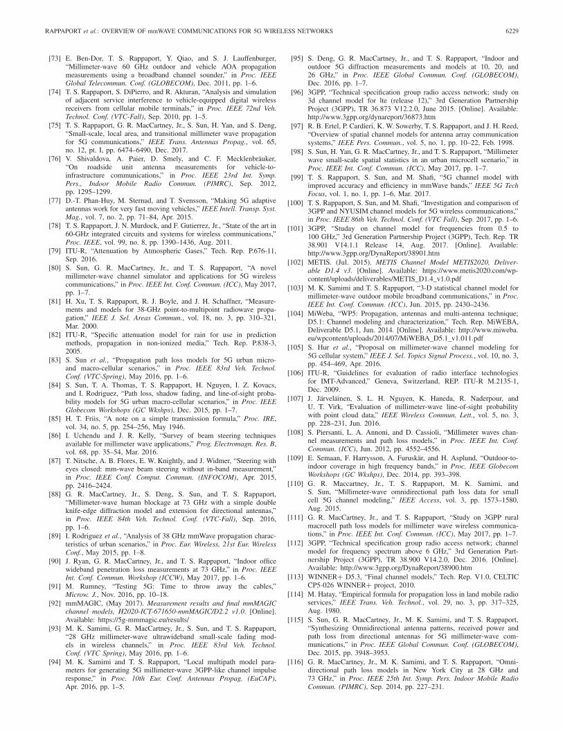
The ITU-R RMa NLOS path loss model from which the3GPP TR38.901 model is adopted is only specified for fre-quencies up to 6 GHz and has not been validated in theliterature for mmWave frequencies. The ITU-R RMa modelswere not developed using rural scenarios [19], [24], but insteadwere derived from measurements in downtown Tokyo, makingthem ill-suited for the RMa case.
c) NYU RMa model: NYU proposed empirically basedCIH RMa path loss models for LOS (P LCIH−RMa
LOS ) and NLOS
TABLE IX
O2I PENETRATION LOSS OF DIFFERENT MATERIALS [101]
(P LCIH−RMaNLOS ) from extensive simulations and 73 GHz field
data [19]
P LCIH−RMaLOS ( fc, d, hBS) [dB]
= 32.4 + 20 log10( fc) + 23.1
(
1 − 0.03
(hBS − 35
35
))
× log10(d) + χσLOS (20)
where d ≥ 1 m, σLOS = 1.7 dB, and 10 m ≤ hBS ≤ 150 m
P LCIH−RMaNLOS ( fc, d, hBS) [dB]
= 32.4 + 20 log10( fc) + 30.7
(
1 − 0.049
(hBS − 35
35
))
× log10(d) + χσNLOS (21)
where d ≥ 1 m, σLOS = 6.7 dB, and 10 m ≤ hBS ≤ 150 m.

6226 IEEE TRANSACTIONS ON ANTENNAS AND PROPAGATION, VOL. 65, NO. 12, DECEMBER 2017
TABLE X
O2I PENETRATION LOSS PARAMETERS [12], [101]
C. O2I Penetration Loss
1) 3GPP TR 38.901: The overall large-scale path lossmodels may also account for penetration loss into a buildingand subsequent path loss inside the building. The O2I path lossmodel taking account of the building penetration loss (BPL)according to 3GPP TR 38.901 [101] has the following form:
P L [dB] = P Lb + P L tw + P L in + N(0, σ 2
P
)(22)
where P Lb is the basic outdoor path loss, P L tw is the BPLthrough the external wall, P L in is the indoor loss whichdepends on the depth into the building, and σP is the standarddeviation for the penetration loss. The BPL P L tw can bemodeled as
P L tw [dB] = P Lnpi − 10 log10
N∑
i=1
(
pi × 10Lmateriali−10
)
(23)
where P Lnpi is an additional loss which is added to theexternal wall loss to account for nonperpendicular incidence,Lmateriali = amateriali + bmateriali · fc is the penetration loss ofmaterial i , fc is the frequency in GHz, pi is the proportionof i th materials, where
∑pi = 1, and N is the number of
materials. Penetration loss of several materials and the O2Ipenetration loss models are given in Table IX.
Rough models are also provided to estimate the BPLin Table X. Both the low-loss and high-loss models areapplicable to UMa and UMi-street canyon, while only the low-loss model is applicable to RMa. The O2I car penetration lossincluded in path loss is determined by
P L [dB] = P Lb + N(μ, σ 2
P
)(24)
where P Lb is the basic outdoor path loss, and for most cases,μ = 9 dB and σP = 5 dB. An optional μ = 20 dB isprovided for metalized car windows for frequencies rangingfrom 0.6 to 60 GHz [101].
2) 5GCM: The 5GCM adopted the BPL model of 3GPPTR 36.873 which is based on legacy measurements below6 GHz [96]. Several different frequency-dependent modelswere also proposed in [12] and [16]. In [109], a detaileddescription of external wall penetration loss using a com-posite approach is provided. The difference of the BPLmodel between 5GCM and 3GPP TR 38.901 is that the stan-dard deviation is tentatively selected from the measurementdata [16], [109]. A very simple parabolic model with a goodfit for predicting BPL of either high-loss or low-loss buildingswas provided in [16] and [99] as
BPL [dB] = 10 log10(
A + B · f 2c
)(25)
where fc is in GHz, A = 5, and B = 0.03 for low-lossbuildings and A = 10 and B = 5 for high-loss buildings.
3) mmMAGIC: The O2I penetration loss model inmmMAGIC has the form of
O2I [dB] = BO2I + CO2I · log10( fc) ≈ 8.5 + 11.2 · log10( fc).
(26)
The advantage of this form is that the coefficients BO2I andCO2I can be added to the existing coefficients in the pathloss model of mmMAGIC. A frequency-dependent SF between8 and 10 dB for the UMi-O2I scenario is presented in [92]
SF [dB] = σSF + δSF · log10( fc) ≈ 5.7 + 2.3 · log10( fc).
(27)
D. Spatial Consistency
Many previous channel models were “drop-based,” where aUE is placed at a random location, random channel parame-ters (conditioned on this location) are assigned, performanceis computed (possibly when moving over a short distance,up to 40 wavelengths), and then a different location ischosen at random. This approach is useful for statistical orMonte-Carlo performance analysis, but does not provide spa-tial consistency, i.e., two UEs that are dropped at nearly iden-tical T-R separation distances might experience completelydifferent channels from a system simulator. The importanceof spatial consistency is dependent upon the site-specificpropagation in a particular location, as shown in [75] and [91].Channel models of 5GCM [12], 3GPP TR 38.901 [101],METIS [102], and MiWEBA [104] provide new approachesfor modeling of trajectories to retain spatial consistency.
In 5GCM and 3GPP, both the LOS/NLOS state and theshadowing states are generated on a coarse grid, and spatiallyfiltered. This resulting “map” of LOS states and shadowingattenuations are then used for the trajectories of all UEs duringthe simulation process. For the implementation of the LOSstate filtering, different methods are proposed [12], [101], butthe effect is essentially the same. We note that 5GCM and3GPP also introduce additional procedures to ensure spatialconsistencies of the delay and angles, but those considerationsare beyond the scope of this paper. The map-based models ofMETIS [102] and MiWEBA [104] inherently provide spatialconsistency, as the dominant paths for close-by locationsare identical, and their effect is computed deterministically.Generally speaking, spatial consistency is easier to implementin geometry-based models (such as semideterministic and

RAPPAPORT et al.: OVERVIEW OF mmWAVE COMMUNICATIONS FOR 5G WIRELESS NETWORKS 6227
geometric-based stochastic channel models) than in tapped-delay line models such as 3GPP. Work in [12], [29], [75], [91],and [92] shows that the degree of spatial consistency can varywidely at mmWave frequencies.
V. CONCLUSION
Often times, standard bodies have additional reasons toadopt particular modeling formulations, beyond physicallaws or the fitting of data to observed channel char-acteristics. Motivations often include ensuring simulationswork for legacy systems at lower frequencies, or thedesire to rapidly converge while preserving legacy appro-aches [19], [28], [80], [111]. Channel modeling for 5G isan on-going process and early results show significant capac-ity differences arise from different models [80], [99], [100].Further work is needed to bolster and validate the earlychannel models. Many new mmWave channel simulators(e.g., NYUSIM, QuaDRiGa) have been developed and arebeing used by researchers to evaluate the performance of com-munication systems and to simulate channel characteristicswhen designing air interfaces or new wireless technologiesacross the network stack [80], [122]–[124].
This paper has provided a comprehensive overview ofemerging 5G mmWave wireless system concepts, and has pro-vided a compilation of important mmWave radio propagationmodels developed throughout the world to date. This paperdemonstrates early standards work and illustrates the variousmodels obtained by several independent groups based onextensive measurements and ray-tracing methods at mmWavefrequency bands in various scenarios.
The development of proper propagation models is vital, notonly for the long-term development of future mmWave wire-less systems but also for fundamental understanding by futureengineers and students who will learn about and improvethe nascent mmWave mobile industry that is just now beingdeveloped. Various companies have started 5G field trials, andsome of them have achieved 20 Gbps date rates [125], [126].The fundamental information on path loss and shadowingsurveyed in this paper is a prerequisite for moving furtheralong the road to 5G at the unprecedented mmWave frequencybands.
VI. ACKNOWLEDGMENT
The authors thank S. Sun of NYU for her suggestions onthis paper.
REFERENCES
[1] J. Gubbi, R. Buyya, S. Marusic, and M. Palaniswami, “Internetof Things (IoT): A vision, architectural elements, and future direc-tions,” Future Generat. Comput. Syst., vol. 29, no. 7, pp. 1645–1660,Sep. 2013.
[2] T. S. Rappaport, “Spectrum frontiers: The new world of millimeter-wave mobile communication,” Invited Keynote Presentation, The Fed-eral Communications Commission (FCC) Headquarters, Mar. 2016.
[3] T. S. Rappaport et al., “Millimeter wave mobile communications for 5Gcellular: It will work!” IEEE Access, vol. 1, pp. 335–349, May 2013.
[4] S. Rangan, T. S. Rappaport, and E. Erkip, “Millimeter-wave cellularwireless networks: Potentials and challenges,” Proc. IEEE, vol. 102,no. 3, pp. 366–385, Mar. 2014.
[5] A. Ghosh et al., “Millimeter-wave enhanced local area systems: A high-data-rate approach for future wireless networks,” IEEE J. Sel. AreasCommun., vol. 32, no. 6, pp. 1152–1163, Jun. 2014.
[6] W. Roh et al., “Millimeter-wave beamforming as an enabling tech-nology for 5G cellular communications: Theoretical feasibility andprototype results,” IEEE Commun. Mag., vol. 52, no. 2, pp. 106–113,Feb. 2014.
[7] Federal Communications Commission, “Spectrum frontiersreport and order and further notice of proposed rulemaking:FCC16-89,” Jul. 2016. [Online]. Available: https://apps.fcc.gov/edocspublic/attachmatch/FCC-16- 89A1 Rcd.pdf
[8] S. Singh, M. N. Kulkarni, A. Ghosh, and J. G. Andrews, “Tractablemodel for rate in self-backhauled millimeter wave cellular networks,”IEEE J. Sel. Areas Commun., vol. 33, no. 10, pp. 2196–2211, Oct. 2015.
[9] K. Sundaresan, M. Y. Arslan, S. Singh, S. Rangarajan, andS. V. Krishnamurthy, “FluidNet: A flexible cloud-based radio accessnetwork for small cells,” IEEE/ACM Trans. Netw., vol. 24, no. 2,pp. 915–928, Apr. 2016.
[10] P. Banelli, S. Buzzi, G. Colavolpe, A. Modenini, F. Rusek, andA. Ugolini, “Modulation formats and waveforms for 5G networks: Whowill be the heir of OFDM?: An overview of alternative modulationschemes for improved spectral efficiency,” IEEE Signal Process. Mag.,vol. 31, no. 6, pp. 80–93, Nov. 2014.
[11] N. Michailow et al., “Generalized frequency division multiplexing for5th generation cellular networks,” IEEE Trans. Commun., vol. 62, no. 9,pp. 3045–3061, Sep. 2014.
[12] 5GCM, “5G channel model for bands up to 100 GHz,” Tech.Rep., Oct. 2016. [Online]. Available: http://www.5gworkshops.com/5GCM.html
[13] K. Haneda et al., “Indoor 5G 3GPP-like channel models for officeand shopping mall environments,” in Proc. IEEE Int. Conf. Commun.Workshops (ICC), May 2016, pp. 694–699.
[14] S. Deng, M. K. Samimi, and T. S. Rappaport, “28 GHz and 73 GHzmillimeter-wave indoor propagation measurements and path lossmodels,” in Proc. IEEE Int. Conf. Commun. Workshop (ICCW),Jun. 2015, pp. 1244–1250.
[15] T. S. Rappaport and S. Deng, “73 GHz wideband millimeter-wavefoliage and ground reflection measurements and models,” in Proc. IEEEInt. Conf. Commun. Workshop (ICCW), Jun. 2015, pp. 1238–1243.
[16] K. Haneda et al., “5G 3GPP-like channel models for outdoor urbanmicrocellular and macrocellular environments,” in Proc. IEEE 83rdVeh. Technol. Conf. (VTC Spring), May 2016, pp. 1–7.
[17] S. Nie, G. R. MacCartney, Jr., S. Sun, and T. S. Rappaport, “72 GHzmillimeter wave indoor measurements for wireless and backhaul com-munications,” in Proc. IEEE 24th Int. Symp. Pers. Indoor Mobile RadioCommun. (PIMRC), Sep. 2013, pp. 2429–2433.
[18] K. Haneda, N. Omaki, T. Imai, L. Raschkowski, M. Peter,and A. Roivainen, “Frequency-agile pathloss models for urbanstreet canyons,” IEEE Trans. Antennas Propag., vol. 64, no. 5,pp. 1941–1951, May 2016.
[19] G. R. MacCartney, Jr., and T. S. Rappaport, “Rural macrocell path lossmodels for millimeter wave wireless communications,” IEEE J. Sel.Areas Commun., vol. 35, no. 7, pp. 1663–1677, Jul. 2017.
[20] T. S. Rappaport, G. R. Maccartney, Jr., M. K. Samimi, and S. Sun,“Wideband millimeter-wave propagation measurements and channelmodels for future wireless communication system design,” IEEE Trans.Commun., vol. 63, no. 9, pp. 3029–3056, Sep. 2015.
[21] G. R. Maccartney, Jr., T. S. Rappaport, S. Sun, and S. Deng, “Indooroffice wideband millimeter-wave propagation measurements and chan-nel models at 28 and 73 GHz for ultra-dense 5G wireless networks,”IEEE Access, vol. 3, pp. 2388–2424, Oct. 2015.
[22] G. R. MacCartney, Jr., J. Zhang, S. Nie, and T. S. Rappaport, “Pathloss models for 5G millimeter wave propagation channels in urbanmicrocells,” in Proc. IEEE Global Commun. Conf. (GLOBECOM),Dec. 2013, pp. 3948–3953.
[23] M. K. Samimi, T. S. Rappaport, and G. R. MacCartney, Jr., “Prob-abilistic omnidirectional path loss models for millimeter-wave out-door communications,” IEEE Wireless Commun. Lett., vol. 4, no. 4,pp. 357–360, Aug. 2015.
[24] G. R. MacCartney, Jr., “Millimeter wave wireless communications:New results for rural connectivity,” in Proc. 5th Workshop All ThingsCellular, Oper., Appl. Challenges, Oct. 2016, pp. 31–36.
[25] S. Sun, G. R. MacCartney, Jr., and T. S. Rappaport, “Millimeter-wavedistance-dependent large-scale propagation measurements and path lossmodels for outdoor and indoor 5G systems,” in Proc. 10th Eur. Conf.Antennas Propag. (EuCAP), Apr. 2016, pp. 1–5.
[26] G. R. MacCartney, Jr., M. K. Samimi, and T. S. Rappaport, “Exploitingdirectionality for millimeter-wave wireless system improvement,” inProc. IEEE Int. Conf. Commun. (ICC), Jun. 2015, pp. 2416–2422.

6228 IEEE TRANSACTIONS ON ANTENNAS AND PROPAGATION, VOL. 65, NO. 12, DECEMBER 2017
[27] T. A. Thomas et al., “A prediction study of path loss models from2–73.5 GHz in an urban-macro environment,” in Proc. IEEE 83rd Veh.Technol. Conf. (VTC Spring), May 2016, pp. 1–5.
[28] S. Sun et al., “Investigation of prediction accuracy, sensitivity, andparameter stability of large-scale propagation path loss models for 5Gwireless communications,” IEEE Trans. Veh. Technol., vol. 65, no. 5,pp. 2843–2860, May 2016.
[29] M. K. Samimi and T. S. Rappaport, “3-D millimeter-wave sta-tistical channel model for 5G wireless system design,” IEEETrans. Microw. Theory Techn., vol. 64, no. 7, pp. 2207–2225,Jul. 2016.
[30] S. Hur, Y.-J. Cho, J. Lee, N.-G. Kang, J. Park, and H. Benn, “Syn-chronous channel sounder using horn antenna and indoor measure-ments on 28 GHz,” in Proc. IEEE Int. Black Sea Conf. Commun.Netw. (BlackSeaCom), May 2014, pp. 83–87.
[31] T. S. Rappaport, F. Gutierrez, Jr., E. Ben-Dor, J. N. Murdock, Y. Qiao,and J. I. Tamir, “Broadband millimeter-wave propagation measure-ments and models using adaptive-beam antennas for outdoor urbancellular communications,” IEEE Trans. Antennas Propag., vol. 61,no. 4, pp. 1850–1859, Apr. 2013.
[32] O. H. Koymen, A. Partyka, S. Subramanian, and J. Li, “Indoor mm-wave channel measurements: Comparative study of 2.9 GHz and29 GHz,” in Proc. IEEE Global Commun. Conf. (GLOBECOM),Dec. 2015, pp. 1–6.
[33] G. P. Fettweis, “The tactile Internet: Applications and challenges,”IEEE Veh. Technol. Mag., vol. 9, no. 1, pp. 64–70, Mar. 2014.
[34] C. F. Mecklenbrauker et al., “Vehicular channel characterization and itsimplications for wireless system design and performance,” Proc. IEEE,vol. 99, no. 7, pp. 1189–1212, Jul. 2011.
[35] J. Gozalvez, M. Sepulcre, and R. Bauza, “IEEE 802.11p vehicle toinfrastructure communications in urban environments,” IEEE Commun.Mag., vol. 50, no. 5, pp. 176–183, May 2012.
[36] N. Bhushan et al., “Network densification: The dominant theme forwireless evolution into 5G,” IEEE Commun. Mag., vol. 52, no. 2,pp. 82–89, Feb. 2014.
[37] A. Maeder, P. Rost, and D. Staehle, “The challenge of M2M com-munications for the cellular radio access network,” in Proc. WürzburgWorkshop IP, Joint ITG Euro-NF Workshop ‘Vis. Future Gener. Netw.’(EuroView), Aug. 2011, pp. 1–2.
[38] A. Nikravesh, Y. Guo, F. Qian, Z. M. Mao, and S. Sen, “An in-depthunderstanding of multipath TCP on mobile devices: Measurement andsystem design,” in Proc. 22nd Annu. Int. Conf. Mobile Comput. Netw.,Oct. 2016, pp. 189–201.
[39] S. Deng et al., “WiFi, LTE, or Both?: Measuring multi-homed wirelessinternet performance,” in Proc. Conf. Internet Meas. Conf., Nov. 2014,pp. 181–194.
[40] J. G. Andrews et al., “What will 5G be?” IEEE J. Sel. Areas Commun.,vol. 32, no. 6, pp. 1065–1082, Jun. 2014.
[41] E. Bastug, M. Bennis, and M. Debbah, “Living on the edge: The roleof proactive caching in 5G wireless networks,” IEEE Commun. Mag.,vol. 52, no. 8, pp. 82–89, Aug. 2014.
[42] N. Carapellese, A. Pizzinat, M. Tornatore, P. Chanclou, and S. Gosselin,“An energy consumption comparison of different mobile backhauland fronthaul optical access architectures,” in Proc. Eur. Conf. Opt.Commun. (ECOC), Sep. 2014, pp. 1–3.
[43] S. Hur, T. Kim, D. J. Love, J. V. Krogmeier, T. A. Thomas, andA. Ghosh, “Millimeter wave beamforming for wireless backhaul andaccess in small cell networks,” IEEE Trans. Commun., vol. 61, no. 10,pp. 4391–4403, Oct. 2013.
[44] H2020 Project 5G-XHaul. (2015). Dynamically ReconfigurableOptical-Wireless Backhaul/Fronthaul With Cognitive Control Planefor Small Cells and Cloud-RANs. [Online]. Available: http://www.5g-xhaulproject.eu/index.html
[45] V. Chandrasekhar, J. G. Andrews, and A. Gatherer, “Femtocell net-works: A survey,” IEEE Commun. Mag., vol. 46, no. 9, pp. 59–67,Sep. 2008.
[46] M. Dohler, R. W. Heath, Jr., A. Lozano, C. B. Papadias, andR. B. Valenzuela, “Is the PHY layer dead?” IEEE Commun. Mag.,vol. 49, no. 4, pp. 159–165, Apr. 2011.
[47] C.-X. Wang et al., “Cellular architecture and key technologies for5G wireless communication networks,” IEEE Commun. Mag., vol. 52,no. 2, pp. 122–130, Feb. 2014.
[48] X. Ge, H. Cheng, M. Guizani, and T. Han, “5G wireless backhaulnetworks: Challenges and research advances,” IEEE Netw., vol. 28,no. 6, pp. 6–11, Nov. 2014.
[49] G. R. MacCartney, Jr., and T. S. Rappaport, “73 GHz millimeterwave propagation measurements for outdoor urban mobile and back-haul communications in New York City,” in Proc. IEEE Int. Conf.Commun. (ICC), Jun. 2014, pp. 4862–4867.
[50] J. N. Murdock and T. S. Rappaport, “Consumption factor and power-efficiency factor: A theory for evaluating the energy efficiency ofcascaded communication systems,” IEEE J. Sel. Areas Commun.,vol. 32, no. 2, pp. 221–236, Feb. 2014.
[51] F. Haider et al., “Spectral efficiency analysis of mobile femtocellbased cellular systems,” in Proc. IEEE 13th Int. Conf. Commun.Technol. (ICCT), Sep. 2011, pp. 347–351.
[52] E. Hossain, M. Rasti, H. Tabassum, and A. Abdelnasser, “Evolu-tion toward 5G multi-tier cellular wireless networks: An interferencemanagement perspective,” IEEE Wireless Commun., vol. 21, no. 3,pp. 118–127, Jun. 2014.
[53] J. Andrews, S. Singh, Q. Ye, X. Lin, and H. Dhillon, “An overviewof load balancing in HetNets: Old myths and open problems,” IEEEWireless. Commun., vol. 21, no. 2, pp. 18–25, Apr. 2014.
[54] M. N. Tehrani, M. Uysal, and H. Yanikomeroglu, “Device-to-devicecommunication in 5G cellular networks: Challenges, solutions, andfuture directions,” IEEE Commun. Mag., vol. 52, no. 5, pp. 86–92,May 2014.
[55] M. Yang, Y. Li, D. Jin, L. Zeng, X. Wu, and A. V. Vasilakos,“Software-defined and virtualized future mobile and wireless networks:A survey,” Mobile Netw. Appl., vol. 20, no. 1, pp. 4–18, Feb. 2015.
[56] P. K. Agyapong, M. Iwamura, D. Staehle, W. Kiess, and A. Benjebbour,“Design considerations for a 5G network architecture,” IEEE Commun.Mag., vol. 52, no. 11, pp. 65–75, Nov. 2014.
[57] J. Van De Beek and F. Berggren, “Out-of-band power suppression inOFDM,” IEEE Commun. Lett., vol. 12, no. 9, pp. 609–611, Sep. 2008.
[58] R. Hadani, et al., “Orthogonal Time Frequency Space Modulation,”Proc. IEEE Wireless Communications and Networking Conf. (WCNC),San Francisco, CA, USA, Mar. 2017, pp. 1–6.
[59] S. Sun, T. S. Rappaport, R. W. Heath, Jr., A. Nix, and S. Rangan,“MIMO for millimeter-wave wireless communications: Beamforming,spatial multiplexing, or both?” IEEE Commun. Mag., vol. 52, no. 12,pp. 110–121, Dec. 2014.
[60] K. Haneda, “Channel models and beamforming at millimeter-wave frequency bands,” IEICE Trans. Commun., vol. 98, no. 5,pp. 755–772, May 2015.
[61] T. S. Rappaport et al., Millimeter Wave Wireless Communications.Upper Saddle River, NJ, USA: Prentice-Hall, 2015.
[62] T. Yamada, T. Nishio, M. Morikura, and K. Yamamoto, “Experimen-tal evaluation of IEEE 802.11ad millimeter-wave WLAN devices,”in Proc. 21st Asia–Pacific Conf. Commun. (APCC), Oct. 2015,pp. 278–282.
[63] A. Siligaris et al., “A 65-nm CMOS fully integrated transceiver modulefor 60-GHz wireless HD applications,” IEEE J. Solid-State Circuits,vol. 46, no. 12, pp. 3005–3017, Dec. 2011.
[64] E. Charfi, L. Chaari, and L. Kamoun, “PHY/MAC enhancementsand QoS mechanisms for very high throughput WLANs: A sur-vey,” IEEE Commun. Surveys Tuts., vol. 15, no. 4, pp. 1714–1735,4th Quart., 2013.
[65] E. Perahia and R. Stacey, Next Generation Wireless LANs: 802.11n and802.11ac. Cambridge, U.K.: Cambridge Univ. Press, 2013.
[66] L. Verma, M. Fakharzadeh, and S. Choi, “Wifi on steroids: 802.11ACand 802.11AD,” IEEE Wireless Commun., vol. 20, no. 6, pp. 30–35,Dec. 2013.
[67] E. Perahia and M. X. Gong, “Gigabit wireless LANs: An overviewof IEEE 802.11ac and 802.11ad,” ACM SIGMOBILE Mobile Comput.Commun. Rev., vol. 15, no. 3, pp. 23–33, Nov. 2011.
[68] E. Perahia, C. Cordeiro, M. Park, and L. L. Yang, “IEEE 802.11ad:Defining the next generation multi-Gbps Wi-Fi,” in Proc. 7th IEEEConsum. Commun. Netw. Conf. (CCNC), Jan. 2010, pp. 1–5.
[69] A. Maltsev et al., “Channel Models for 60 GHz WLAN Systems,”Tech. Rep., doc: IEEE 802.11-09/0334r8, May 2010, Beijing.
[70] A. Maltsev, A. Pudeyev, A. Lomayev, and I. Bolotin, “Channel model-ing in the next generation mmWave Wi-Fi: IEEE 802.11ay standard,”in Proc. 22nd Eur. Wireless Conf. Eur. Wireless, May 2016, pp. 1–8.
[71] IEEE Standard for Information Technology—Telecommunications andInformation Exchange Between Systems—Local and Metropolitan AreaNetworks—Specific Requirements—Part 11: Wireless LAN MediumAccess Control (MAC) and Physical Layer (PHY) Specifications, IEEEStandard 802.11p, Sep. 2010.
[72] H. Moustafa and Y. Zhang, Vehicular Networks: Techniques, Standards,and Applications. New York, NY, USA: Auerbach, 2009.
RAPPAPORT et al.: OVERVIEW OF mmWAVE COMMUNICATIONS FOR 5G WIRELESS NETWORKS 6229
[73] E. Ben-Dor, T. S. Rappaport, Y. Qiao, and S. J. Lauffenburger,“Millimeter-wave 60 GHz outdoor and vehicle AOA propagationmeasurements using a broadband channel sounder,” in Proc. IEEEGlobal Telecommun. Conf. (GLOBECOM), Dec. 2011, pp. 1–6.
[74] T. S. Rappaport, S. DiPierro, and R. Akturan, “Analysis and simulationof adjacent service interference to vehicle-equipped digital wirelessreceivers from cellular mobile terminals,” in Proc. IEEE 72nd Veh.Technol. Conf. (VTC-Fall), Sep. 2010, pp. 1–5.
[75] T. S. Rappaport, G. R. MacCartney, Jr., S. Sun, H. Yan, and S. Deng,“Small-scale, local area, and transitional millimeter wave propagationfor 5G communications,” IEEE Trans. Antennas Propag., vol. 65,no. 12, pt. I, pp. 6474–6490, Dec. 2017.
[76] V. Shivaldova, A. Paier, D. Smely, and C. F. Mecklenbräuker,“On roadside unit antenna measurements for vehicle-to-infrastructure communications,” in Proc. IEEE 23rd Int. Symp.Pers., Indoor Mobile Radio Commun. (PIMRC), Sep. 2012,pp. 1295–1299.
[77] D.-T. Phan-Huy, M. Sternad, and T. Svensson, “Making 5G adaptiveantennas work for very fast moving vehicles,” IEEE Intell. Transp. Syst.Mag., vol. 7, no. 2, pp. 71–84, Apr. 2015.
[78] T. S. Rappaport, J. N. Murdock, and F. Gutierrez, Jr., “State of the art in60-GHz integrated circuits and systems for wireless communications,”Proc. IEEE, vol. 99, no. 8, pp. 1390–1436, Aug. 2011.
[79] ITU-R, “Attenuation by Atmospheric Gases,” Tech. Rep. P.676-11,Sep. 2016.
[80] S. Sun, G. R. MacCartney, Jr., and T. S. Rappaport, “A novelmillimeter-wave channel simulator and applications for 5G wirelesscommunications,” in Proc. IEEE Int. Conf. Commun. (ICC), May 2017,pp. 1–7.
[81] H. Xu, T. S. Rappaport, R. J. Boyle, and J. H. Schaffner, “Measure-ments and models for 38-GHz point-to-multipoint radiowave propa-gation,” IEEE J. Sel. Areas Commun., vol. 18, no. 3, pp. 310–321,Mar. 2000.
[82] ITU-R, “Specific attenuation model for rain for use in predictionmethods, propagation in non-ionized media,” Tech. Rep. P.838-3,2005.
[83] S. Sun et al., “Propagation path loss models for 5G urban micro-and macro-cellular scenarios,” in Proc. IEEE 83rd Veh. Technol.Conf. (VTC-Spring), May 2016, pp. 1–6.
[84] S. Sun, T. A. Thomas, T. S. Rappaport, H. Nguyen, I. Z. Kovacs,and I. Rodriguez, “Path loss, shadow fading, and line-of-sight proba-bility models for 5G urban macro-cellular scenarios,” in Proc. IEEEGlobecom Workshops (GC Wkshps), Dec. 2015, pp. 1–7.
[85] H. T. Friis, “A note on a simple transmission formula,” Proc. IRE,vol. 34, no. 5, pp. 254–256, May 1946.
[86] I. Uchendu and J. R. Kelly, “Survey of beam steering techniquesavailable for millimeter wave applications,” Prog. Electromagn. Res. B,vol. 68, pp. 35–54, Mar. 2016.
[87] T. Nitsche, A. B. Flores, E. W. Knightly, and J. Widmer, “Steering witheyes closed: mm-wave beam steering without in-band measurement,”in Proc. IEEE Conf. Comput. Commun. (INFOCOM), Apr. 2015,pp. 2416–2424.
[88] G. R. MacCartney, Jr., S. Deng, S. Sun, and T. S. Rappaport,“Millimeter-wave human blockage at 73 GHz with a simple doubleknife-edge diffraction model and extension for directional antennas,”in Proc. IEEE 84th Veh. Technol. Conf. (VTC-Fall), Sep. 2016,pp. 1–6.
[89] I. Rodriguez et al., “Analysis of 38 GHz mmWave propagation charac-teristics of urban scenarios,” in Proc. Eur. Wireless, 21st Eur. WirelessConf., May 2015, pp. 1–8.
[90] J. Ryan, G. R. MacCartney, Jr., and T. S. Rappaport, “Indoor officewideband penetration loss measurements at 73 GHz,” in Proc. IEEEInt. Conf. Commun. Workshop (ICCW), May 2017, pp. 1–6.
[91] M. Rumney, “Testing 5G: Time to throw away the cables,”Microw. J., Nov. 2016, pp. 10–18.
[92] mmMAGIC, (May 2017). Measurement results and final mmMAGICchannel models, H2020-ICT-671650-mmMAGIC/D2.2 v1.0. [Online].Available: https://5g-mmmagic.eu/results/
[93] M. K. Samimi, G. R. MacCartney, Jr., S. Sun, and T. S. Rappaport,“28 GHz millimeter-wave ultrawideband small-scale fading mod-els in wireless channels,” in Proc. IEEE 83rd Veh. Technol.Conf. (VTC Spring), May 2016, pp. 1–6.
[94] M. K. Samimi and T. S. Rappaport, “Local multipath model para-meters for generating 5G millimeter-wave 3GPP-like channel impulseresponse,” in Proc. 10th Eur. Conf. Antennas Propag. (EuCAP),Apr. 2016, pp. 1–5.
[95] S. Deng, G. R. MacCartney, Jr., and T. S. Rappaport, “Indoor andoutdoor 5G diffraction measurements and models at 10, 20, and26 GHz,” in Proc. IEEE Global Commun. Conf. (GLOBECOM),Dec. 2016, pp. 1–7.
[96] 3GPP, “Technical specification group radio access network; study on3d channel model for lte (release 12),” 3rd Generation PartnershipProject (3GPP), TR 36.873 V12.2.0, June 2015. [Online]. Available:http://www.3gpp.org/dynareport/36873.htm
[97] R. B. Ertel, P. Cardieri, K. W. Sowerby, T. S. Rappaport, and J. H. Reed,“Overview of spatial channel models for antenna array communicationsystems,” IEEE Pers. Commun., vol. 5, no. 1, pp. 10–22, Feb. 1998.
[98] S. Sun, H. Yan, G. R. MacCartney, Jr., and T. S. Rappaport, “Millimeterwave small-scale spatial statistics in an urban microcell scenario,” inProc. IEEE Int. Conf. Commun. (ICC), May 2017, pp. 1–7.
[99] T. S. Rappaport, S. Sun, and M. Shafi, “5G channel model withimproved accuracy and efficiency in mmWave bands,” IEEE 5G TechFocus, vol. 1, no. 1, pp. 1–6, Mar. 2017.
[100] T. S. Rappaport, S. Sun, and M. Shafi, “Investigation and comparison of3GPP and NYUSIM channel models for 5G wireless communications,”in Proc. IEEE 86th Veh. Technol. Conf. (VTC Fall), Sep. 2017, pp. 1–6.
[101] 3GPP, “Studay on channel model for frequencies from 0.5 to100 GHz,” 3rd Generation Partnership Project (3GPP), Tech. Rep. TR38.901 V14.1.1 Release 14, Aug. 2017. [Online]. Available:http://www.3gpp.org/DynaReport/38901.htm
[102] METIS. (Jul. 2015). METIS Channel Model METIS2020, Deliver-able D1.4 v3. [Online]. Available: https://www.metis2020.com/wp-content/uploads/deliverables/METIS_D1.4_v1.0.pdf
[103] M. K. Samimi and T. S. Rappaport, “3-D statistical channel model formillimeter-wave outdoor mobile broadband communications,” in Proc.IEEE Int. Conf. Commun. (ICC), Jun. 2015, pp. 2430–2436.
[104] MiWeba, “WP5: Propagation, antennas and multi-antenna technique;D5.1: Channel modeling and characterization,” Tech. Rep. MiWEBA,Deliverable D5.1, Jun. 2014. [Online]. Available: http://www.miweba.eu/wpcontent/uploads/2014/07/MiWEBA_D5.1_v1.011.pdf
[105] S. Hur et al., “Proposal on millimeter-wave channel modeling for5G cellular system,” IEEE J. Sel. Topics Signal Process., vol. 10, no. 3,pp. 454–469, Apr. 2016.
[106] ITU-R, “Guidelines for evaluation of radio interface technologiesfor IMT-Advanced,” Geneva, Switzerland, REP. ITU-R M.2135-1,Dec. 2009.
[107] J. Järveläinen, S. L. H. Nguyen, K. Haneda, R. Naderpour, andU. T. Virk, “Evaluation of millimeter-wave line-of-sight probabilitywith point cloud data,” IEEE Wireless Commun. Lett., vol. 5, no. 3,pp. 228–231, Jun. 2016.
[108] S. Piersanti, L. A. Annoni, and D. Cassioli, “Millimeter waves chan-nel measurements and path loss models,” in Proc. IEEE Int. Conf.Commun. (ICC), Jun. 2012, pp. 4552–4556.
[109] E. Semaan, F. Harrysson, A. Furuskär, and H. Asplund, “Outdoor-to-indoor coverage in high frequency bands,” in Proc. IEEE GlobecomWorkshops (GC Wkshps), Dec. 2014, pp. 393–398.
[110] G. R. Maccartney, Jr., T. S. Rappaport, M. K. Samimi, andS. Sun, “Millimeter-wave omnidirectional path loss data for smallcell 5G channel modeling,” IEEE Access, vol. 3, pp. 1573–1580,Aug. 2015.
[111] G. R. MacCartney, Jr., and T. S. Rappaport, “Study on 3GPP ruralmacrocell path loss models for millimeter wave wireless communica-tions,” in Proc. IEEE Int. Conf. Commun. (ICC), May 2017, pp. 1–7.
[112] 3GPP, “Technical specification group radio access network; channelmodel for frequency spectrum above 6 GHz,” 3rd Generation Part-nership Project (3GPP), TR 38.900 V14.2.0, Dec. 2016. [Online].Available: http://www.3gpp.org/DynaReport/38900.htm
[113] WINNER+ D5.3, “Final channel models,” Tech. Rep. V1.0, CELTICCP5-026 WINNER+ project, 2010.
[114] M. Hatay, “Empirical formula for propagation loss in land mobile radioservices,” IEEE Trans. Veh. Technol., vol. 29, no. 3, pp. 317–325,Aug. 1980.
[115] S. Sun, G. R. MacCartney, Jr., M. K. Samimi, and T. S. Rappaport,“Synthesizing Omnidirectional antenna patterns, received power andpath loss from directional antennas for 5G millimeter-wave com-munications,” in Proc. IEEE Global Commun. Conf. (GLOBECOM),Dec. 2015, pp. 3948–3953.
[116] G. R. MacCartney, Jr., M. K. Samimi, and T. S. Rappaport, “Omni-directional path loss models in New York City at 28 GHz and73 GHz,” in Proc. IEEE 25th Int. Symp. Pers. Indoor Mobile RadioCommun. (PIMRC), Sep. 2014, pp. 227–231.

6230 IEEE TRANSACTIONS ON ANTENNAS AND PROPAGATION, VOL. 65, NO. 12, DECEMBER 2017
[117] J. B. Andersen, T. S. Rappaport, and S. Yoshida, “Propagation mea-surements and models for wireless communications channels,” IEEECommun. Mag., vol. 33, no. 1, pp. 42–49, Jan. 1995.
[118] K. Bullington, “Radio propagation at frequencies above 30 megacy-cles,” Proc. IRE, vol. 35, no. 10, pp. 1122–1136, Oct. 1947.
[119] M. J. Feuerstein, K. L. Blackard, T. S. Rappaport, S. Y. Seidel, andH. Xia, “Path loss, delay spread, and outage models as functions ofantenna height for microcellular system design,” IEEE Trans. Veh.Technol., vol. 43, no. 3, pp. 487–498, Aug. 1994.
[120] 3GPP, “Correction for low and high frequency model harmonization,”Ericsson, Samsung, NTT DOCOMO, Nokia, Intel, Telstra, TDOCR1-1701195, Jan. 2017.
[121] 3GPP, “New measurements at 24 GHz in a rural macro environment,”Telstra, Ericsson, Tech. Rep. TDOC R1-164975, May 2016.
[122] V. K. Rajendran et al., “Concepts and implementation of a semanticWeb archiving and simulation system for RF propagation measure-ments,” in Proc. IEEE Veh. Technol. Conf. (VTC-Fall), Sep. 2011,pp. 1–5.
[123] S. Jaeckel, L. Raschkowski, K. Borner, and L. Thiele, “QuaDRiGa:A 3-D multi-cell channel model with time evolution for enablingvirtual field trials,” IEEE Trans. Antennas Propag., vol. 62, no. 6,pp. 3242–3256, Jun. 2014.
[124] New York University. NYUSIM. (2016). [Online]. Available: http://wireless.engineering.nyu.edu/nyusim/
[125] Huawei. (Jul. 2016). 5G: Huawei and Vodafone Achieve 20 Gbpsfor Single-User Outdoor at E-Band. [Online]. Available: http://www.huawei.com/en/news/2016/7/huawei-vodafone-5g-test
[126] Ericsson. (Sep. 2016). Ericsson and Telstra Conduct the First Live5G Trial in Australia. [Online]. Available: https://www.ericsson.com/news/160920-ericsson-telstra-5g-trial-australia_244039854_c
[127] J. Lee et al., “Measurement-based propagation channel characteris-tics for millimeter-wave 5G Giga communication systems,” ETRI J.,vol. 38, no. 6, pp. 1031–1041, Dec. 2016.
Theodore S. Rappaport, photograph and biography can be found on p. 6211of Part I of this issue.
Yunchou Xing, photograph and biography not available at the time ofpublication.
George R. MacCartney, Jr., photograph and biography not available at thetime of publication.
Andreas F. Molisch, photograph and biography not available at the time ofpublication.
Evangelos Mellios, photograph and biography not available at the time ofpublication.
Jianhua Zhang, photograph and biography not available at the time ofpublication.