ieee p802.15 ig thz ted - ieee standards … · web viewthe inspection sensitivity required for...
TRANSCRIPT

SeptemberNovember, 2014 18-14/0075r013
ScopeThis Report contains technology trends of active services in the band above 275 GHz. This Report intends to provide technical information for preparation of sharing and compatibility studies between active and passive services, as well as among active services in the band above 275 GHz.
Abbreviations and acronymsATR Attenuated Total Reflection spectrometryBNA N-Benzyl-2-Methyl-4-NitroanilineBWO Backward-Wave OscillatorDAST Diethylaminosulfur TrifluorideDFG Difference Frequency GenerationFEL Free-Electron LaserFTIR Fourier Transform Infrared spectroscopyHBT Heterojunction Bipolar TransistorHEMT High Electron Mobility TransistorIMPATT Impact Ionization Avalanche Transit-TimeLoS Line of SightLT-GaAs Low Temperature grown Gallium ArsenideMMIC Monolithic Microwave Integrated CircuitNEP Noise Equivalent PowerNFC Near Field CommunicationNLoS Non Line of SightQCL Quantum Cascade LaserRTD Resonant Tunnelling DiodeTDS Time Domain SpectroscopyTNNNET Tunnel Injection Transit-TimeTHz Terahertz
Submission Page
Radiocommunication Study Groups
Source: Document 1A/TEMP/57 (edited) Annex 2 toDocument 1A/166-E24 June 2014English only
Annex 2 to Working Party 1A Chairman’s Report
PRELIMINARY DRAFT NEWREPORT ITU-R SM.[THZ.TREND]
Technology trends of active services in the band above 275 GHz
SeptemberNovember, 2014 18-14/0075r013
UTC-PD Uni-Traveling-Carrier Photodiode
ReferencesRecommendation ITU-R P.676: Attenuation by atmospheric gasesRecommendation ITU-R P.838: Specific attenuation model for rain for use in prediction
methodsRecommendation ITU-R P.840: Attenuation due to clouds and fogReport ITU-R RS.2194: Passive bands of scientific interest to EESS/SRS from 275
to 3 000 GHz Report ITU-R RA.2189: Sharing between the radio astronomy service and active
services in the frequency range 275-3 000 GHzReport ITU-R F.2107-2: Characteristics and applications of fixed wireless systems
operating in frequency ranges between 57 GHz and 134 GHz
APT/ASTAP/REPT-04: Technology trends of telecommunications above 100 GHz
1 1 Introduction The spectrum of frequencies above 275 GHz is not allocated for specific services, but identified for passive service in the Radio Regulation (RR). The spectrum regulation of frequencies above 3 000 GHz is still under study in accordance with Resolution 118 (Marrakesh, 2002). At the World Radiocommunication Conference 2012 (WRC-12), RR No. 5.565 was amended in accordance with Resolution 950 (Rev.WRC-07)to identify for use by administrations for passive service applications, such as radio astronomy service, earth exploration-satellite service (passive) and space research service (passive). However, the use of the range 275-1 000 GHz by the passive services does not preclude use of this range by active services.New Question ITU-R 237/1,”Technical and operational characteristics of the active services” was developed and approved in 2013 to encourage administrations to study the technical and operational characteristics of active services in the frequency range 275-1 000 GHz. In addition to the technical and operational characteristics, sharing studies between active and passive services, as well as among active services are expected to be carried out taking into account those characteristics in accordance with the new Question ITU-R 237/1. Due to remarkable progress in the recent technologies above 275 GHz, the integrated devices and circuits operating above 275 GHz enable us to achieve the sophisticated applications, such as spectroscopy, imaging, non-destructive testing and THz camera. Although the advantages of such high frequencies are to use ultra-broad bandwidth which cannot be allotted in the microwave and millimetre-wave frequency bands, , those advantages are not yet utilized to develop the ultra-high speedwireless communication systems. In order to reflect the advancement of terahertz (THz) technologies into the radiocommunication applications, it is necessary and urgent to understand the current technology trends of active services in the band above 275 GHz.In addition to remarkable progress of THz technologies, IEEE 802 currently established IEEE 802.15.3d Task Group to develop an IEEE 802 standard operating that includes also a PHY layer operating beyond 275 GHz at THz frequency ranges. However, the frequency ranges above 275 GHz for active services are not yet identified, nor have allocations made to any service in this range in the Radio Regulation. It is also urgent from the regulatory point-of-view to understand
Submission Page

SeptemberNovember, 2014 18-14/0075r013
technical and operational characteristics of active systems to avoid interference between the passive services operating in this rangeandthe active servicesto be developed and deployed in the near future.This Report overviews the technology trend of active systems studied in the band above 275 GHz and intends to provide technical information for preparation of sharing and compatibility studies. The technologies discussed in this Report are in the areas of THz wireless communication, sensing and imaging.
2 2 Regulatory information No. 5.565 of the Radio Regulationwas amended to identify for use by administrations for passive service applications, such as radio astronomy service, earth exploration-satellite service (passive) and space research service (passive) at WRC-12. RR (Edition of 2012) No. 5.565 is shown below:
275-3 000 GHz
Allocation to services
Region 1 Region 2 Region 3275-3 000 (Not allocated) MOD 5.565
5.565 The following frequency bands in the range 275-1 000 GHz are identified for use by administrations forpassive service applications:– radio astronomy service: 275-323 GHz, 327-371 GHz, 388-424 GHz, 426-442
GHz,453-510 GHz, 623-711 GHz, 795-909 GHz and 926-945 GHz;– Earth exploration-satellite service (passive) and space research service (passive):
275-286 GHz,296-306 GHz, 313-356 GHz, 361-365 GHz, 369-392 GHz, 397-399 GHz, 409-411 GHz,416-434 GHz, 439-467 GHz, 477-502 GHz, 523-527 GHz, 538-581 GHz, 611-630 GHz,634-654 GHz, 657-692 GHz, 713-718 GHz, 729-733 GHz, 750-754 GHz, 771-776 GHz,823-846 GHz, 850-854 GHz, 857-862 GHz, 866-882 GHz, 905-928 GHz, 951-956 GHz,968-973 GHz and 985-990 GHz.
The use of the range 275-1 000 GHz by the passive services does not preclude use of this range by activeservices. Administrations wishing to make frequencies in the 275-1 000 GHz range available for active serviceapplications are urged to take all practicable steps to protect these passive services from harmful interference until thedate when the Table of Frequency Allocations is established in the above-mentioned 275-1 000 GHz frequency range.All frequencies in the range 1 000-3 000 GHz may be used by both active and passive services. (WRC-12)
3 3 THz wireless communication There are a number of research activities on ultra-broadband wireless communication systems in the frequency band above 275 GHz. Some researches aim at ultra-high-speed wireless communication systems which interface 40-Gbps and 100-Gbps Ethernet. Due to high capacity transmission capabilityand large propagation loss of communication links using THz
Submission Page

SeptemberNovember, 2014 18-14/0075r013
technologies, these links can operate as the last mile access links. Several trials using the frequency above 275 GHz have been demonstrated by R&D organizations.
3.1 3.1 Possible use caseof THz communication systems In examining use cases of THz communications, the following specific points should be considered:• Utilization of ultrawide frequency band width• Possibility of miniaturization of antenna and device• High directivity and large free space propagation loss (wavelength is less than 1/5 of
the 60GHz band, and although free space propagation loss is 25 times or more, it is compensated by high gain antenna characteristics)
• Development of manufacturing technology such as for oscillators, power amplifiers, and beam steering antennae
3.1.1 3.1.1 Super-proximity communication between chips and between circuit boards
Figure 1 shows a use case of super-proximity communication between chips and between circuit boards. Wirelessly connecting parts and circuit boards are expected to have the effect of eliminating wiring and miniaturizing substrates and devices. Table 1 shows the typical requirements of this use case. It is summarised that communication distances when implementing ICs and/or layering IC-implemented substrates in the same housing will range from a few mm to a few tens of cm. Regarding transmission speed, a speed of 10 Gbps has already been prescribed for USB3.1, and for PCIExpress4.0, a transfer speed for the data link layer has been standardized at 4 GB/sec = 32 Gbps (bidirectional), and additionally, up to 4 GB/sec x 64 = 256 GB/sec (2 Tbps) which bundles up to 64 lanes have been specified. While it is not always necessary to support communication exceeding Tbps, with communication between chips and between circuit boards utilizing THz communication, ultra high speed transmission exceeding at least a few tens of Gbps will be required. Regarding propagation environment, it is necessary to examine both LoS and NLoS communication as a proximity model or super-proximity in housing which assumes a metallic housing accompanied by the strong reflective waves. It is necessary to consider the effect of multipath between devices arranged in super-proximity, and multipath via device housing inner walls by the penetration of THz waves through substrates.
Submission Page

SeptemberNovember, 2014 18-14/0075r013
FIGURE 1
Use case of super-proximity communication between chips and between circuit boards
TABLE 1
Typical requirements.
Communication distance A few mm to a few cm (super-proximity to proximity)Data speed A few tens of Gbps
Propagation environment Super-proximity in housing and proximity model (LoS/NLoS)Required BER 10-9
3.1.2 3.1.2 Content synchronization with the cloud through near field communication
Figure 2 shows a use case of content synchronization with the cloud through near field communication. Recently, services which utilize the cloud have been rapidly increasing, together with collaboration services between a rapidly increasing smartphone and the cloud. Cloud storage service is one of cloud services which store photos and video shot on a user’s smartphone through a network without making the user conscious of this synching process. However, packet communication utilizing 3G and LTE used by smartphones to frequently synchronize contents on the cloud without the user being conscious of it, leads to unexpected increases in battery consumption. This use case assumes that, in addition to IC charging function at automated ticket gates at train stations, users can possess smartphones equipped with THz communication function. When passing through a train station ticket gate on your way to the office or school, simultaneously content synchronization through THz communication will suppress smartphone battery consumption. Table 2 shows the typical requirements for these use cases. Although communication distance is less than a few cm, to synchronize an effective data volume or content during a very short time period of about 1 second, it is desirable that communication speed be made as fast as possible. For this purpose, in addition to communication speed, it will also be necessary to develop an
Submission Page

SeptemberNovember, 2014 18-14/0075r013
authentication and association system which will enable the communication link establishment time to be made very short. On the other hand, even if THznear field communication exceeding 100 Gbps is feasible, it is necessary to investigate whether or not the storage reading and writing speed, which smartphones assumed in these use cases are equipped with, is compatible with such high speed transmission. As one example, the reading and writing speed of SSD (Solid State Disc) declared to presently be the fastest in the world, is about 500 Mbytes/sec. (4 Gbps).It is also assumed that the propagation environment will be an inter-device proximity model which applies only to LoS. Investigating whether or not multipath reflections between devices in proximity will affect data transfer needs to be studied.
FIGURE 2
Use case of content synchronizationwith the cloud through near field communication
TABLE 2
Typical requirementsCommunication distance Up to a few cm (proximity)
Data speed 4 Gbps – a few tens of GbpsPropagation environment Inter-device proximity model (LoS)
Required BER 8% PER (before retransmission control)TBD
3.1.3 Wirelesscommunication between servers inside a data centerFigure 3 shows a use case ofTHz communication between servers inside a data center. Recently, services utilizing the cloud have been rapidly increasing and have accelerated the construction of data centers. Generally, several server racks equipped with various servers including storage and multiple switches can be found in data centers, and it is desirable that the wiring between servers within server racks and the wiring between racks be made wireless.Table 3 shows the typical requirements in this use case. Communication distances from a few cm, assuming connection between servers arranged vertically within server racks, to a few m assuming connection between racks. Regarding the propagation environment, it is necessary to consider both LoS and NLoS which assumes an office model where building materials with comparatively low permeability
Submission Page

SeptemberNovember, 2014 18-14/0075r013
(high reflectivity) are utilized, but if we envision a special case where the server rack is placed near the wall surface and cable connections between rear panels are replaced by THz communication link, a two-wave ray model can be applied between rear panels.
FIGURE 3
Wireless communication between servers inside a data center
TABLE 3
Typical requirementsCommunication distance A few cm – a few m (proximity)
Data speed A few tens of Gbps – a few hundreds of GbpsPropagation environment Office model/two-raywave model (LoS/NLoS)
Required BER 10-12 8 % PER (before retransmission control)
3.1.4 Wireless Backhauling/FronthaulingA backhaul link is a connection between the base station and a more centralized network element, whereas the fronthaul link is the link between the radio equipment controller of a base station and the remote radio head (radio unit). Future developments like massive deployment of small cells, the implementation of cooperative multipoint transmission (CoMP) and/or Cloud Radio Access Networks (C-RAN) may increase the required data rates for either fronthauling or backhauling or both. Realizing these links using wireless links may be attractive in situations, where fiber links are not available. In cases, where several tens of Gbit/s are required the THz frequency range can be seen as an attractive solution. In the demonstration described in [1] a data rate of 24 Gbit/s has been achieved over a link distance of 1 km.
TABLE 4
Typical requirementsCommunication distance 500 m to 1 km
Submission Page

SeptemberNovember, 2014 18-14/0075r013
Data speed up to 100 GbpsPropagation environment outdoor
Required BER Tbd
3.2 3.2 THz transceiver technologies
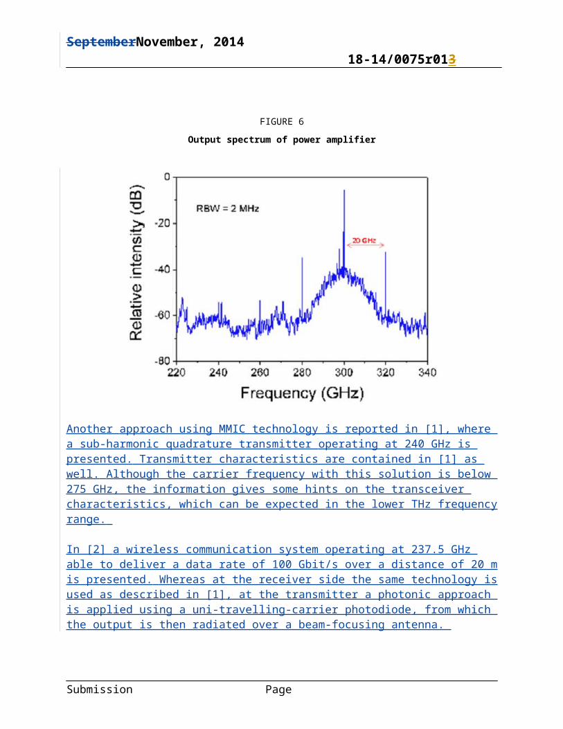
3.2.1[3.1.3] 3.2.1 300GHz transceiver using MMICFigure 4 shows a block diagram of the overall structure of a transmitter module. A diagonal horn antenna, power amplifier, modulator, and multiplier are mounted in the metal waveguide package. The multiplier multiples 75GHz carrier generated by local oscillator and the 20GHzsignals are supplied to the modulator. To evaluate the transmission module, an evaluation system is configured by installing a receiver module to perform evaluation. The receiver module consists of a standard horn antenna (24dBi) and a waveguide module equipped with a Schottky barrier diode. Figure 5 shows the measured spectrum of a 20 Gbps ASK signal (300 GHz) at the power amplifier output terminal. A modulating signal at a center frequency of 300GHz+/-20GHz was observed by the output spectrum the modulator, as shown in Figure 6.
FIGURE 4
Block diagram of transmitter module
Submission Page

SeptemberNovember, 2014 18-14/0075r013
FIGURE 5
Eyediagram of 20 Gbps signal of transmitter module
FIGURE 6
Output spectrum of power amplifier
Another approach using MMIC technology is reported in [1], where a sub-harmonic quadrature transmitter operating at 240 GHz is presented. Transmitter characteristics are contained in [1] as well. Although the carrier frequency with this solution is below 275 GHz, the information gives some hints on the transceiver characteristics, which can be expected in the lower THz frequency range.
Submission Page

SeptemberNovember, 2014 18-14/0075r013
In [2] a wireless communication system operating at 237.5 GHz able to deliver a data rate of 100 Gbit/s over a distance of 20 m is presented. Whereas at the receiver side the same technology is used as described in [1], at the transmitter a photonic approach is applied using a uni-travelling-carrier photodiode, from which the output is then radiated over a beam-focusing antenna.
[3.1.4] 3.2.2 300GHz transceiver using RTDThe oscillator is the so-called resonant tunneling diode (RTD), whichoscillates at an appropriate DC bias voltage. By changing the bias voltage, 300-GHz carrier signal ismodulated as ON and OFF depending on the amplitude of the bias voltage. As for the receiver, thedirect-detection receiver is used, as shown in Figure 7. The maximum bit rate was 1.5 Gbps and thetransmission of uncompressed HDTV signals was succeeded by diode technologies. It is also demonstrated that the RTD can be also operated as a detector with high sensitivity. An error-free 2.5 Gbpstransmission at 625 GHz using frequencymultiplier for the transmitterwas also demonstrated.
FIGURE 7
Block diagram of the wireless link using diode technologies
[Editor’s note: Information on technical characteristics of THz transceiversneeds to be further provided to prepare for sharing studies between passive and active services at the next meeting]
4 4 Sensing and imaging THz waves possess moderate substance permeability and good spatial resolution, as well as unique characteristics which other electromagnetic frequency bands do not have, such as spectral
Submission Page

SeptemberNovember, 2014 18-14/0075r013
fingerprinting of reagents, differentiation of single-stranded and double-stranded DNA, absorption difference of water and ice, and sensitivity toward semiconductor impurities; moreover, THz waves are also safe for the human body. Based on these facts, a wide-range of sensing and imaging applications are expected.
4.1 4.1 THz Generation Method Table 4 summarizes the relationship between THz generation methods and their technologies.
Submission Page

SeptemberNovember, 2014 18-14/0075r013
TABLE 4
THz generation methods and their technologies
Generation Method
Generation Technology
Material Function
Ultra-short pulse photoexcitation
Photoconductive antenna LT-GaAs THz-TDSRoom temperature operation
Nonlinear optics ParametricDFG
GaAs, GaP, GaSe , ZGP, PPLN, BD-GaAs, OP-GaAs
Variable wavelengthRoom temperature operation
Photomixing PhotoconductorUTC-PD
LT-GaAsInP/InGaAs
Room temperature operation
Laser QCL GaAs/AlGaAs, InGaAs-AlInAs/InP
Narrow linewidthCryogenic temperature operation
Solid state electronics Gunn, IMPATT, RTDCompound Semiconductor
GaAs, InP, SiAlAs/GaInAs/AlAsHBT, HEMT, mHEMT, pHENT
Fixed wavelengthRoom temperature operation
Electron tube BWO, Gyrotron Variable wavelengthRoom temperature operation
(1) Ultrashort pulse photoexcitationPresently, this is the most common THz pulse generation method. By photoexciting non-linear crystal (NLC), photo-conductive antenna (PCA), semiconductors, and superconductors, etc. using an ultrashort pulsed laser with a duration of about a femtosecond, subpicosecond photoconductive current modulations within semiconductors can be brought about, and a wide band THz optical pulse can be generated by utilizing secondary non-linear polarization (light rectification) using non-resonant, non-linear media. This method is widely utilized in THz Time Domain Spectroscopy (THz-TDS).THz-TDS has an extremely high signal to noise ratio (S/N ratio) compared to the Fourier transform far-infrared spectrophotometer using a conventional thermal light source, and is being applied in THz spectroscopy and imaging, etc. Although the structure, crystal makeup, and excitation laser wavelength should be respectively selected for the structure of the photo-conductive antenna, and the semiconductor and non-linear crystal, owing to recent advancements in ultrashort pulse laser technology, and by using a regenerative amplifier to generate a high strength pulsed light as the excitation light, a THz pulse possessing a high electric field strength can be derived.
(2) Non-linear opticsThis generation method is classified into parametric generation and difference frequency generation (DFG). Parametric generation involves wavelength conversion by way of phonon polaritons within non-linear crystals such as LiNbO3. It features tunable wavelength and
Submission Page
SeptemberNovember, 2014 18-14/0075r013
operation at room temperature, and the miniaturization of light source size from desktop-size to palm-size is possible together with the miniaturization of excitation lasers. Recently, a peak strength THz pulse exceeding 1kW has been derived, which is comparable to values using a free-electron laser (FEL).On the other hand, difference frequency generation (DFG) is the generation of a difference frequency utilizing the secondary non-linear optical effect of non-linear crystals. In recent years, generation methods with organic crystals such as DAST and BNA have been reported, and in terms of generation strength, mW output using intracavity DFG have been reported.
Submission Page

SeptemberNovember, 2014 18-14/0075r013
(3) Photomixing By injecting a two-wavelength laser light into a photo-conductive device or photo diode, a THz wave which is an optical differential frequency is generated applying photoelectric conversion through photomixing. As for the photo diode, THz light exceeding 1THz can be generated owing to the uni-traveling-carrier photodiode (UTC-PD) possessing high speed and high output characteristics.(4) LaserThe quantum cascade laser (QCL) possesses a structure which is layered with semiconductor materials of different energy barrier heights in nanometer-order thicknesses, and realizes laser oscillation through intersubband transition. Although, in principle, it will be a very narrow line width, in actuality it is limited to low temperature operation (max. operating temperature through pulse drive is 200K). However, the output power at a frequency exceeding 1THz is relatively large. (5) Solid-state electronicsThey traditionally developed as microwave or millimeter-wave devices. Gunn diodes utilize intervalley transition having conduction bands with different effective masses, and Impact Ionization Avalanche Transit-Time (IMPATT) diodes and Tunnel Injection Transit-Time (TNNETT) diodes are transit time diodes which create structurally high field areas where electrons travel. RTDs consist a double barrier structure with semiconductor thin film, and realize differential negative resistance using the tunneling phenomenon which occurs there, deriving a basic oscillation exceeding 1THz (although output is small).As a practical high frequency semiconductor device currently applied in oscillators, amplifiers, and even MMIC (Monolithic microwave integrated circuit), there is HBT (Heterojunction bipolar transistor) which utilizes compound semiconductors, and HEMT (High electron mobility transistor). While InP type semicoductors with material characteristics such as high electron mobility are expected to operate faster, there also have been reports of devices which operate at more than a few hundred GHz, by applying technology such as pHEMT (pseudomorphic HEMT) and mHEMT (metamorphic HEMT) which aspire toward higher speeds. (6) Electron tubeTHzwave is generated by the backward-wave oscillator (BWO) through the interaction of the slow wave circuit and electrons; by Smith-Purcell radiation through the Smith-Purcell effect which occurs when electrons pass over a metallic diffraction grating; by the gyrotron through the cyclotron resonance maser action involving electron mass changes due to the relativistic effect. While output is generally large, housing size is also large.
4.2 4.2 THz Cameras The following are trends in the THz two dimensional array sensor which is based on bolometer-type non-cooled infrared array sensor technology. Figure 8 shows an image of an infrared camera equipped with two dimensional infrared array sensor with a pixel count 320x240 and a pixel pitch 23.5m when injected withQCL of a 3.1THz frequency. The pixel structure in this case has an additional THz absorption layer, and by adjusting the metallic thin film sheet resistance from a vacuum impedance matched to 377 , sensitivity at approximately 3THz is improved by about 1 digit (Figure 9(a)). In addition, the
Submission Page

SeptemberNovember, 2014 18-14/0075r013
narrow bandwidth THz array sensor shown in Figure 9 (b) has been developed for the purpose of improving sensitivity by an additional 2–4 times only at certain wavelengths.Figure 10 shows the wavelength dependency of the NEP (noise equivalent power) for the wide bandwidth and narrow bandwidth THz array sensors themselves. As can be seen by looking at the characteristics of the wide bandwidth THz array sensor, it exhibits roughly flat NEP characteristics from wavelength 3 m to a little less than 200 m, and NEP starts to worsen from above 200 m. Figure 11 and Table 5 show an external view and specifications of a palm-size THz camera equipped with one of the two types of array sensors, a wide bandwidth THz array sensor. Using high resistivity silicon as THz lens material, a parylene film as a non-reflective coating is formed on the silicon. As well, an infrared blocking filter (metal mesh filter which allows transmission of wavelengths more than about 30 m) is attached in front of the THz lens. This camera can be driven from a computer via a USB 2.0 interface and also can record digital image data to a computer.
Submission Page

SeptemberNovember, 2014 18-14/0075r013
FIGURE 8(A) (B) NARROWBAND
Broadband THz array sensor, THz array sensor
FIGURE 9
QCL beam pattern of THz array sensor with a pixel count 320x240 and a pixel pitch 23.5m
FIGURE 10
Wavelength dependency of NEP of THz array sensor
Submission Page

SeptemberNovember, 2014 18-14/0075r013
FIGURE 11
External view of THz camera
TABLE 5
Specification of THz cameraMethod Bolometer type
Array format Pixel count: 320 240Pixel pitch: 23.5m
Visual field Approx. 15 11(when equipped with a focal point distance 28mm lens)
Frame rate 30HzOutput Digital image data: USB2.0
Synchronous signal: BNCLock-in imaging function Synchronous signal: 15Hz, 7.5Hz, 3.75Hz, 1.875Hz (TTL output: +5V)Signal processing function Frame integration
Spatial filterWeight Approx. 550g (not including lens and filter)
4.3 4.3 Spectroscopy Spectroscopic systems can beclassified into the conventional Fourier transform infrared spectrometer (FTIR), and the wavelength sweeping spectroscopic system and THz time domain spectroscopic system (THz-TDS). The Martin-Puplet system which is an extension of conventional infrared technology is an example of the FTIR. Wavelength sweeping spectroscopic systemsutilize a backward-wave tube to directly change the wavelength of a THz wave, and difference frequency methods which utilize two variable wavelength lasers. However there are issues with the variable range and wavelength accuracy.
4.3.1
Submission Page

SeptemberNovember, 2014 18-14/0075r013
4.3.2 4.3.1 THz-TDS (Time Domain Spectroscopy)A powerful new tool for measuring in the THz region called THz-TDS was developed in the past decade. Electric waveforms of mono-cycleTHz radiation pulse are generated and measured by gated detection with a short NIR laser pulse. Usually, the mono-cycleTHz radiation pulse contains very wide range of spectrum, typically, between 100 GHz and 10 THz. This method is becoming popular for material diagnosis.
4.3.3 4.3.2 FTIR (Fourier Transform Infrared) spectroscopyMany materials have a so-called finger print spectra in the frequency range above 275 GHz.Indeed spectroscopy in the frequency range above around 1 000 GHz has been used since 1960s, and some commercial products have been already developed. The system covers the frequency band fully up to mid-infrared range. In the mid-infrared band, spectra depend on intra-molecule behaviour, and spectral libraries of almost all standard chemicals are available. Thus chemists can use a commercial system as a common tool to identify unknown materials. In the far-infrared region, or in THz frequency band, the fingerprint spectra depend on inter-molecule behaviour, phonon absorption, hydrogen bonds, or similar molecules conditions. Unlike mid-infrared there is no commercial spectral library.
4.3.4 4.3.3 Material analysisSolid and liquid property analysis is performed applying THz-TDS. THz band polarimetry is used, for example, for evaluating material birefringence characteristics at each frequency. Utilizing this kind of evaluation function, devices are also starting to be marketed which are equipped with analysis functions for the development of new materials, such as analysis of polymer optical isomers. On the other hand, although THz waves are very susceptible to absorption by water, it has become possible to measure samples containing water, which was traditionally considered difficult in application, utilizing attenuated total reflection spectrometry (ATR method) at THz frequencies. With this method, as sample characteristics can be derived without penetrating water, it is also possible to detect cells within the culture fluid using the ATR method, and is being anticipated as an effective method for THz applications in biotechnology.
4.4 4.4 Non-destructive testing
4.4.1 4.4.1 Industrial products applicationsThe demand for THz imaging in industrial products and materials continues to be very strong-rooted. This is because only radio waves to THz bands, or radiation such as X-rays can be used to see through opaque objects in visible light. Of these, the handling of ionized radiation such as X rays is accompanied by risk and constraints, while radio waves to THz bands have low energy as quanta and are non-ionizing, and X rays are generally problematic in terms of detecting light elements such as carbon. Of radio waves to THz bands, compared to microwaves among others which, in principle, have long wavelengths and poor image resolution (spatial resolution),
Submission Page
SeptemberNovember, 2014 18-14/0075r013
milliwaves to THz waves which achieve spatial resolution at mm order or less have a far greater utility for application in imaging.In industrial products, non-metallic materials which transmit THz waves are abundant in our everyday lives. Some of the most typical of these products are made of plastics, vinyl, and paper, while others are made of ceramics and rubber and possess various functions and often have high added value. As examples, there are medical components which utilize the heat resistance of ceramics and the flexibility of rubber. These products are widely used in the energy area and medical area, and are highly needed in foreign particle detection. The size of defects is frequently at least about 1–10 m, and a high S/N ratio and speed are required. THz CT technology is promising as THz imaging technology in non-destructive testing which cannot be managed using X rays. THzwaves which can derive spectroscopic information can detect defects, as well as information on what kind of defects they are, and are attracting attention as a technology which can bring new added value to analysis. Defects which require detection include foreign particles, as well as thin film unevenness and defects in coating, etc. The desired accuracy depth is generally about a few m, but in an inspection of semiconductor substrates etc., there are cases when electrical characteristics of thin film thickness of less than about a few 100nm are required. Although measuring such thin film was thought to be difficult using THz waves, owing to recent advances in technology development, this is starting to be shown to be possible.
4.4.2 4.4.2 Biological and medical applicationsNowadays, clinical inspection applications are wide ranging from inspections for lifestyle diseases to cancer markers, if we include research applications. Of the basic principles for sensing in-vivo target proteins etc., there are many which are modelled after the recognition mechanism of organisms such as the antigen-antibody reaction. However, for a human to discern the presence/absence of this recognition, one level higher processing is required. For example, in the detection method for allergens utilizing an inspection method called enzyme immunoassay, a capture antibody which specifically binds with the allergen is affixed to a substrate, and after reacting with a sample, the presence/absence of this allergen is detected using a detection antibody or detection marker. In this way, multi-stage reactions are employed to indicate the test results through colour or fluorescence. Such markers have been designed to efficiently produce colour through the slightest reaction with the substrate, and in chemiluminescent measurements, detection sensitivity in the order of picogram is achieved. However, multi-stage inspections also have issues such as requiring numerous reagents and long inspection time, as well as an increase in error factors through multi-stage processing.Within this background, a German research group in 2000 reported on the possibility of no marker detection using THz waves. These researchers showed in their experiments that there were differences in THz band refractive index and transmittance in single-stranded and double-stranded DNA. Later, a research group in the U.S. proposed a method of detecting the binding of avidin and biotin through the phase delay in the THz-TDS time waveform. This means that it is possible to detect the presence/absence of binding, without the use of markers, from changes in the refractive index and absorbance of biological polymers at THz bands. In Japan, utilizing an imaging measuring system comprised of a quantum cascade laser and THz camera, a line of
Submission Page

SeptemberNovember, 2014 18-14/0075r013
small-molecule compounds were affixed on a membrane filter, and proteins which specifically bind with them were successfully detected in image format, verifying that it is possible to detect biological substances such as proteins swiftly, conveniently, and in a marker-free fashion. On the other hand, there is the issue of detection sensitivity as an important technology development theme. The inspection sensitivity required for clinical inspections is in the range of milligram to picogram, and the inspection sensitivity particularly in the range from nanogram to picogram is most needed in no marker inspections. As an example of inspection applications requiring such small sensitivity, application in predictive diagnosis for autoimmune diseases stemming from autoantibodies in the blood can be raised.Generally, protection from the invasion of bacteria and viruses from the outside occurs through immune reaction within the body. However, with autoimmune diseases, substances involved in immunity within the body attack the body. For example, with type 1 diabetes, autoantibodies which target three types of pancreatic proteins have been discovered, and it is known that 70–90% of patients possess at least one of these autoantibodies. In addition, the relationship between these three autoantibodies and their incidence has been investigated, and clear relationships have beenpresented. Therefore, by conducting preliminary inspections to know whether or not these autoantibodies exist within the body, onset can be predicted, and they can also be used in prevention.It is desirable that such inspections be performed for health examinations, and it is important that inspection technology which is convenient, fast, and cheap be developed. When applied in health examinations, it is ideal if various diseases can be predicted in one inspection, and not just for type I diabetes indicated here. In other words, to perform inspections at one time by reacting the autoantigens of various diseases affixed onto a single inspection chip with small amounts of autoantibodies found in drawn blood, technology that can perform no marker inspections and detect picogram order biological substances is require. Among clinical inspections, test drugs for conventional immune serum inspections, including inspections based on antigen-antibody reaction, were expected to have a domestic market of 157.2 billion yen in FY2008 and 168 billion yen in FY2013, according to a survey conducted by Fuji-Keizai. This market amounts to over 40% of the test drug market, and occupies the highest ratio. With their advent, no marker and high accuracy inspection technology is expected to enter these markets and contribute to the expansion of market size.On the other hand, such needs for no marker and trace substance inspection are assumed in various settings, and their spillover effect is great. They include the security field in inspecting dangerous gases, bacteriological weapons, and explosives; infectious virus inspection such as for new type influenzas where there are concerns of pandemic; and inspection of trace substances in the environment, residual pesticides in agricultural products, and residual antibiotics in livestock. Therefore, it is important to pursue the early development of no marker inspection technology as an infrastructure, research relating to the selectivity of inspection substances based on this technology, and R&D to improve detection sensitivity. As one technology to improve the detection sensitivity of THz waves, there is a method utilizing a metallic mesh as a sensor, which has led to technologies enabling the detection of proteins in the order of nanogram/mm.By merging technology for the no marker detection of trace substances with imaging technology, the range of uses will continue to expand. In particular, it will be possible to comprehensively inspect proteins which specifically bind to small molecule arrays and sugar chain arrays, and will become a technology which can advance into the drug discovery field. In addition, no marker
Submission Page

SeptemberNovember, 2014 18-14/0075r013
detection using THz wave technology will clarify the existence of proteins which have been overlooked until now as they could not be marked, and is expected to become a powerful screening technology in life science research.
5 5 THz related activities within the international standard organization
[Editor’s note: IEEE802 is invited to provide their THz standardization activityto this section]
In 2008 IEEE 802.15 created the THz Interest Group (IG THz). The focus was primarily concerned with THz communications and related network applications operating in the THz frequency bands between 275 – 3000 GHz. Such THz communication applications would include: component to component, board to board, machine to machine, human to machine and human to human, (indoor and outdoor) wireless communications. THz communication applications cover multiple categories with varying requirements. As envisioned, THz communications would overall employ wireless modulation methods of limited complexity, omni and/or directional antenna systems, and would typically offer very high data transfer rates in multiples of 10 Gbps, and up to 100 Gbps, for parity with future fiber optic capacities. THz wireless systems could support transmission distances ranging from the very short (few centimeters or less) to relatively long distances of several hundred meters.
The IG THz has focused on open spectrum issues, channel modelling and monitoring the development of technology.With the development of more mature transceiver technologies 802.15 made a step forward towards the development of a new standard by establishing a study group in July 2013 with the scope of determining the validity of a standard on 100G (100 Gbit/s over beam switchable wireless point-to-point 40/100 Gbps links). The study group completed its work in March 2014 with the establishment of Task Group 3d. Based on IEEE 802.15.3c , an amendment will be prepared by the task group, which defines a wireless switched point-to-point physical layer to IEEE Std. 802.15.3 operating at PHY data rates typically in the range of up to of 100 Gbps or more with fallback solutions at lower data rates if necessary. Operation is considered in bands from 60 GHz up to and including optical wireless at ranges as short as a few centimeters and up to several hundred meters. Additionally, modifications to the Medium Access Control (MAC) layer, needed to support this new physical layer, are defined. Potential applications of interest include wireless data centers, kiosk downloading, wireless intra-device communication and wireless backhauling and fronthauling. Although the initial focus of the IG THz has been the frequency range beyond 275 GHz, in the Task Group 3d the frequency range will be kept open to other bands such as the consideration of 60 GHz and free space optics (FSO). Hence, the wave length of interest for the PHY will be millimeter-wave or shorter.A key issue in the prosess of developing the amendment is the identification of concrete frequency bands beyond 275 GHz. Key issues in selecting appropriate frequency bands are the gaseous attenuation characteristics in the frequency range from 100 GHz to 1000 GHz. There is the specific resonant attenuation by oxygen and water vapour as documented in [6]. The contiguous band of interest for THz communications is simply estimated by avoiding the
Submission Page

SeptemberNovember, 2014 18-14/0075r013
corresponding resonance attenuation lines. Table 6 summarizes the suitable frequency range and the contiguous bandwidth .
Table 6 Suitable frequency range and contiguous bandwidth
Frequency range (GHz) Contiguous bandwidth (GHz) Additional loss by resonant attenuation
(dB/km)200-320 120 < 10275-320 45 < 10335-360 25 < 10275-370 95 < 100380-445 65 < 100455-525 70 < 100625-725 100 < 100780-910 130 < 100
Apart from the consideration of attenuation characteristics also the maturity of technology plays an important role. Based on demonstrations of transmission experiments and on ongoing research projects it is likely that within TG 802.15.3d the frequency band between 275 GHz and 325 GHz will be the target.
It is expected that a call for proposals will be issued in the second half of 2015 targeting to complete the standard in the first half of 2017. In parallel the IG THz is still active in monitoring technologcial developments relevant for other use cases than those covered by TG3d. This will eventually trigger the creation of one or more study groups considering standards in the THz frequency range.
6 6 Initial Consideration of Sharing with Passive Services There may be several practical practicable steps that administrations and manufacturers can take in order to protect passive services in the 275-1 000 GHz. RR 5.565“Administrations wishing to make frequencies in the 275-1 000 GHz range available for active service applications are urged to take all practicable steps to protect these passive services from harmful interference until the date when the Table of Frequency Allocations is established in the above-mentioned 275-1 000 GHz frequency range.”[Editor’s note: Administrations are asked to provide information regarding sharing between active and passive services within the 275-1 000 GHz frequency range to the next meeting]
Within IEEE 802.15, results on interference investigations have been presented in sharing scenarios between active and passive services. As a result of the investigations power masks have been derived. The affect on radio astronomy by THz
Submission Page

SeptemberNovember, 2014 18-14/0075r013
communications has been considered in [3]. Reference [4] presents results on scenarios, which are critical with respect to earth exploration satelite services. The most critical scenarios are:
– Outdoor-operated nomadic devices in rural or urban environments– Fixed links with scattering objects close to ray path or sidelobe emission– Airborne transmitters relevant for both nadir and limb scanning
The impact of interference from multiple stations has been investigated. The report also suggests measures to avoid interference from THz communcations to earth exploration satelite services. The sharing studies have been also published in full detail in [5]
7 7 Conclusions The characteristics of THz devices and systems discussed in this Report are rapidly being improved by the advancement of device technologies. THz wireless communication systems, in particular, may have large potential to transmit high data rate close to 100Gbps whose speed is currently discussed within IEEE802. The sharing study between passive and active services and the review of RR needs to be taken into account to introduce those devices into market in the near future.
8[7] Bibliography[1] J. Antes et. al. High Data Rate Wireless Communication using a 240 GHz Carrier IEEE 802.15-14-0017-00-0thz, Los Angeles, January 2014 ; https://mentor.ieee.org/802.15/dcn/14/15-14-0017-00-0thz-high-data-rate-wireless-communication-using-a-240-ghz-carrier.pdf[2] S. König et. al; Wireless sub-THz communication system with high data rate, Nature Photonics 7, 977–981 (2013), http://www.nature.com/nphoton/journal/vaop/ncurrent/abs/nphoton.2013.275.html[3] A. Clegg: Sharing between radio astronomy and active services at THz frequencies, IEEE 802.15-10-0829-00-0thz, Dallas, October 2010; https://mentor.ieee.org/802.15/dcn/10/15-10-0829-00-0thz-sharing-between-active-and-passive-services-at-thz-frequencies.ppt[4] S. Priebe: Interference between THz Communications and Spaceborne Earth Exploration Services, IEEE 802.15-12-0324-00-0thz, San Diego, July 2012; https://mentor.ieee.org/802.15/dcn/12/15-12-0324-00-0thz-interference-between-thz-communications-and-spaceborne-earth-exploration-services.pdf[5] Priebe, S.; Britz, D. M.; Jacob, M.; Sarkozy, S.; Leong, K. M. K.; Logan, J. E.; Gorospe, B.; Kürner, T.: Interference Investigations of Active Communications and Passive Earth Exploration Services in the THz Frequency Range. IEEE Transactions on Terahertz Science and Technology, Vol. 2, No. 5, S. 525– 537, 2012.; http://ieeexplore.ieee.org/xpl/login.jsp?tp=&arnumber=6280646&url=http%3A%2F%2Fieeexplore.ieee.org%2Fxpls%2Fabs_all.jsp%3Farnumber%3D6280646[6] Recommendation ITU-R P.676-9, “Attenuation by atmospheric gases”
Submission Page